


COS-4

1000 Park Drive • Lawrence, PA 15055-1018 • 724-746-5500 • Fax 724-746-0746
© Copyright 1998. Black Box Corporation. All rights reserved.
FEDERAL COMMUNICATIONS COMMISSION
AND
CANADIAN DEPARTMENT OF COMMUNICATIONS
RADIO FREQUENCY INTERFERENCE STATEMENTS
This equipment generates, uses, and can radiate radio frequency
energy and if not installed and used properly, that is, in strict
accordance with the manufacturer’s instructions, may cause
interference to radio communication. It has been tested and
found to comply with the limits for a Class A computing device
in accordance with the specifications in Subpart J of Part 15 of
FCC rules, which are designed to provide reasonable protection
against such interference when the equipment is operated in a
commercial environment. Operation of this equipment in a
residential area is likely to cause interference, in which case the
user at his own expense will be required to take whatever
measures may be necessary to correct the interference.
Changes or modifications not expressly approved by the party
responsible for compliance could void the user’s authority to
operate the equipment.
This digital apparatus does not exceed the Class A limits for radio
noise emission from digital apparatus set out in the Radio
Interference Regulation of the Canadian Department of
Communications.
Le présent appareil numérique n’émet pas de bruits radioélectriques
dépassant les limites applicables aux appareils numériques de
classe A prescrites dans le Règlement sur le brouillage
radioélectrique publié par le ministère des Communications du
Canada.
TRADEMARKS USED IN THIS MANUAL
AT, IBM, and PS/2 are registered trademarks, and PC/XT is a
trademark, of International Business Machines Corporation.
FCC AND DOC/MDC STATEMENTS
3
HIGH SPEED COS-4 AND HIGH SPEED COS-8
NORMAS OFICIALES MEXICANAS (NOM) ELECTRICAL SAFETY STATEMENT
INSTRUCCIONES DE SEGURIDAD
1. Todas las instrucciones de seguridad y operación deberán ser leídas
antes de que el aparato eléctrico sea operado.
2. Las instrucciones de seguridad y operación deberán ser guardadas
para referencia futura.
3. Todas las advertencias en el aparato eléctrico y en sus instrucciones de
operación deben ser respetadas.
4. Todas las instrucciones de operación y uso deben ser seguidas.
5. El aparato eléctrico no deberá ser usado cerca del agua—por ejemplo,
cerca de la tina de baño, lavabo, sótano mojado o cerca de una alberca,
etc.
6. El aparato eléctrico debe ser usado únicamente con carritos o
pedestales que sean recomendados por el fabricante.
7. El aparato eléctrico debe ser montado a la pared o al techo sólo como
sea recomendado por el fabricante.
8. Servicio—El usuario no debe intentar dar servicio al equipo eléctrico
más allá a lo descrito en las instrucciones de operación. Todo otro
servicio deberá ser referido a personal de servicio calificado.
9. El aparato eléctrico debe ser situado de tal manera que su posición no
interfiera su uso. La colocación del aparato eléctrico sobre una cama,
sofá, alfombra o superficie similar puede bloquea la ventilación, no se
debe colocar en libreros o gabinetes que impidan el flujo de aire por los
orificios de ventilación.
10. El equipo eléctrico deber ser situado fuera del alcance de fuentes de
calor como radiadores, registros de calor, estufas u otros aparatos
(incluyendo amplificadores) que producen calor.
11. El aparato eléctrico deberá ser connectado a una fuente de poder sólo
del tipo descrito en el instructivo de operación, o como se indique en el
aparato.
4
NOM STATEMENT
12. Precaución debe ser tomada de tal manera que la tierra fisica y la
polarización del equipo no sea eliminada.
13. Los cables de la fuente de poder deben ser guiados de tal manera que
no sean pisados ni pellizcados por objetos colocados sobre o contra
ellos, poniendo particular atención a los contactos y receptáculos donde
salen del aparato.
14. El equipo eléctrico debe ser limpiado únicamente de acuerdo a las
recomendaciones del fabricante.
15. En caso de existir, una antena externa deberá ser localizada lejos de las
lineas de energia.
16. El cable de corriente deberá ser desconectado del cuando el equipo no
sea usado por un largo periodo de tiempo.
17. Cuidado debe ser tomado de tal manera que objectos liquidos no sean
derramados sobre la cubierta u orificios de ventilación.
18. Servicio por personal calificado deberá ser provisto cuando:
A: El cable de poder o el contacto ha sido dañado; u
B: Objectos han caído o líquido ha sido derramado dentro del
aparato; o
C: El aparato ha sido expuesto a la lluvia; o
D: El aparato parece no operar normalmente o muestra un cambio en
su desempeño; o
E: El aparato ha sido tirado o su cubierta ha sido dañada.
5
HIGH SPEED COS-4 AND HIGH SPEED COS-8
Contents
Chapter Page
1. Specifications ........................................................................................ 7
2. Introduction ......................................................................................... 9
3. Configuration ..................................................................................... 10
3.1 Selecting the Operating Mode ................................................... 10
3.2 Setting Communication Parameters ........................................... 10
3.3 Choosing an Arming Code .......................................................... 11
3.4 Setting Ports as DTE or DCE ...................................................... 11
4. Installation .......................................................................................... 20
4.1 Placement ..................................................................................... 20
4.2 Cabling ......................................................................................... 20
4.3 Power Connection ....................................................................... 22
5. Operation ........................................................................................... 25
5.1 Power-Up ..................................................................................... 25
5.2 Switching ...................................................................................... 25
5.3 The Barber-Pole Self-Test ........................................................... 26
6. Troubleshooting ................................................................................. 27
6.1 First Steps ..................................................................................... 27
6.2 Calling Your Supplier ................................................................. 27
6.3 Shipping and Packaging .............................................................. 28
6
7
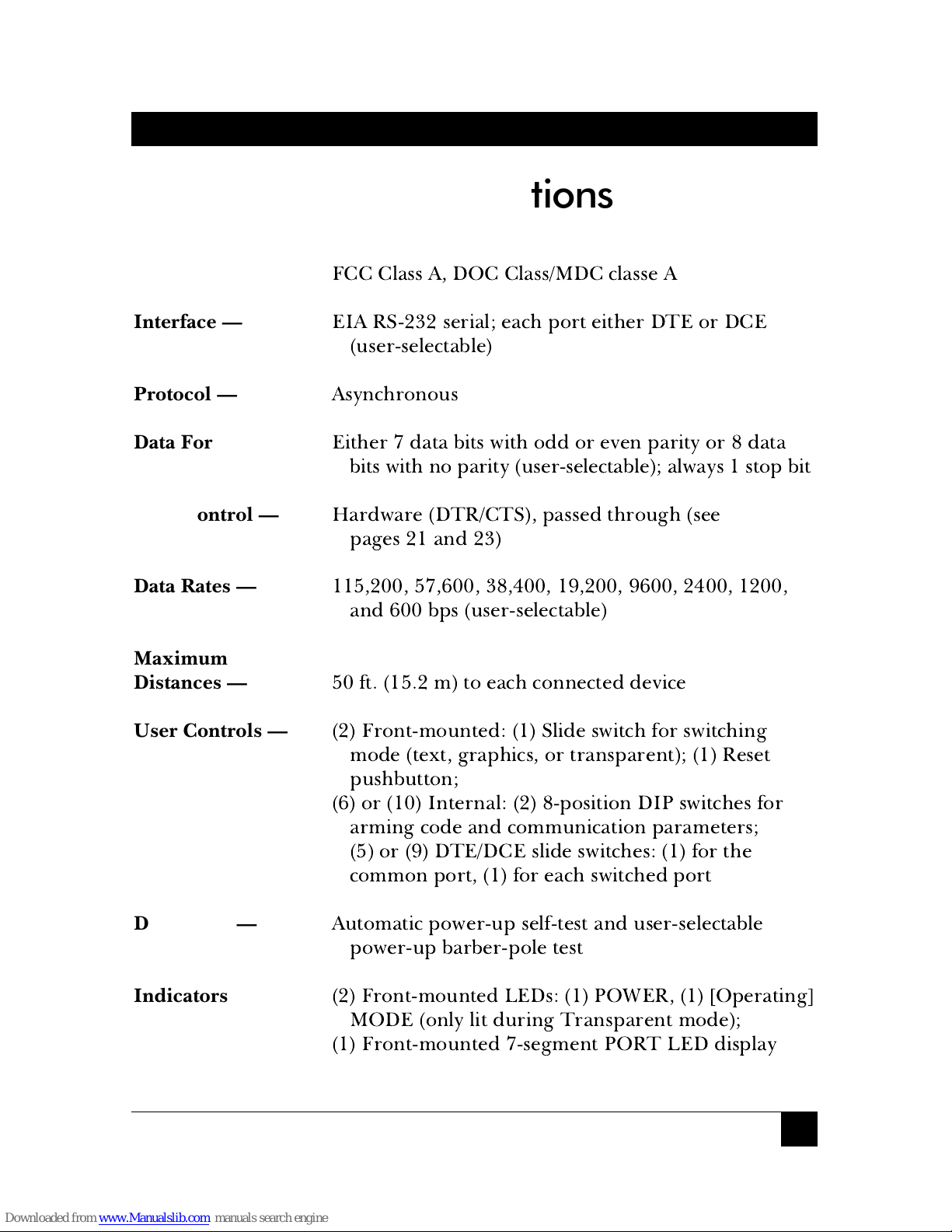
CHAPTER 1: Specifications
Compliance —
FCC Class A, DOC Class/MDC classe A
Interface —
EIA RS-232 serial; each port either DTE or DCE
(user-selectable)
Protocol —
Asynchronous
Data Format —
Either 7 data bits with odd or even parity or 8 data
bits with no parity (user-selectable); always 1 stop bit
Flow Control —
Hardware (DTR/CTS), passed through (see
pages 21 and 23)
Data Rates —
115,200, 57,600, 38,400, 19,200, 9600, 2400, 1200,
and 600 bps (user-selectable)
Maximum
Distances —
50 ft. (15.2 m) to each connected device
User Controls —
(2) Front-mounted: (1) Slide switch for switching
mode (text, graphics, or transparent); (1) Reset
pushbutton;
(6) or (10) Internal: (2) 8-position DIP switches for
arming code and communication parameters;
(5) or (9) DTE/DCE slide switches: (1) for the
common port, (1) for each switched port
Diagnostic —
Automatic power-up self-test and user-selectable
power-up barber-pole test
Indicators —
(2) Front-mounted LEDs: (1) POWER, (1) [Operating]
MODE (only lit during Transparent mode);
(1) Front-mounted 7-segment PORT LED display
1. Specifications
8
HIGH SPEED COS-4 AND HIGH SPEED COS-8
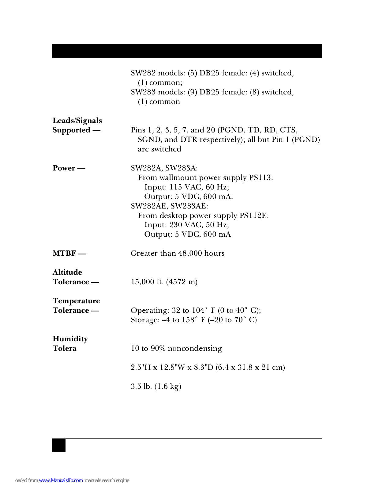
Connectors —
SW282 models: (5) DB25 female: (4) switched,
(1) common;
SW283 models: (9) DB25 female: (8) switched,
(1) common
Leads/Signals
Supported —
Pins 1, 2, 3, 5, 7, and 20 (PGND, TD, RD, CTS,
SGND, and DTR respectively); all but Pin 1 (PGND)
are switched
Power —
SW282A, SW283A:
From wallmount power supply PS113:
Input: 115 VAC, 60 Hz;
Output: 5 VDC, 600 mA;
SW282AE, SW283AE:
From desktop power supply PS112E:
Input: 230 VAC, 50 Hz;
Output: 5 VDC, 600 mA
MTBF —
Greater than 48,000 hours
Altitude
Tolerance —
15,000 ft. (4572 m)
Temperature
Tolerance —
Operating: 32 to 104˚ F (0 to 40˚ C);
Storage: –4 to 158˚ F (–20 to 70˚ C)
Humidity
Tolerance —
10 to 90% noncondensing
Size —
2.5"H x 12.5"W x 8.3"D (6.4 x 31.8 x 21 cm)
Weight —
3.5 lb. (1.6 kg)
9
CHAPTER 2: Introduction
With the High Speed COS-4 or High Speed COS-8, you can send a code
sequence from an asynchronous RS-232 device and switch between four or
eight other such devices. By using this electronic method to switch, you
avoid the problems that can occur (especially with laser printers) when you
switch manually. You can select any two-byte sequence as the “arming code”
(the code that causes the COS to switch).
The High Speed COS-4 and COS-8 have three modes of operation, which
you can choose between with the slide switch on the front panel. In Text
mode, the user can send the chosen arming code, followed by the ASCII
character corresponding to the desired port (from “1” to “4” or “8,” or “0”
for no port, or “9” for all ports), immediately following other data. In
Graphics mode, the arming code and port character are not recognized
unless they are preceded by a pause. (You can select the length of this
pause.) In Transparent mode, arming codes are not recognized and
switching does not occur; arming codes will be passed through the COS
until it is set to a different mode.
2. Introduction
10
HIGH SPEED COS-4 AND HIGH SPEED COS-8
Before you install the High Speed COS-4 or High Speed COS-8, you
should configure it for your application.
Section 3.1
describes setting the
front-panel Mode switch to select your desired operating mode.
Section 3.2
describes setting the internal DIP switch SW1 so that the COS operates
using the communication parameters that you need;
Section 3.3
describes
how to choose your arming code by setting the internal DIP switch SW2;
Section 3.4
describes how to use the internal slide switches to set each port
as DTE or DCE.
3.1 Selecting the Operating Mode
Use the slide switch labeled “TX GR TR” on the front of the High-Speed
COS-4 or COS-8 to select which operating mode you want the unit to start
in. In the left-hand (TX) position, the Text mode is selected; in the center
(GR) position, the Graphics mode is selected; in the right-hand (TR)
position, the Transparent mode is selected. In Text and Graphics modes,
the MODE LED is dark; in Transparent mode, the MODE LED is lit to
alert you that switching is diabled until you change modes. (See
Chapter 2
and
Section 5.2
for descriptions of these modes.)
3.2 Setting Communication Parameters
Making sure that the unit is unplugged and powered down, open the High
Speed COS-4 or COS-8 by unscrewing and removing six screws (three on the
left side of the unit, three on the right side), then removing the unit’s cover.
Use the DIP switch labeled SW11 inside the unit to set its communications
parameters. As shown in Table 3-1 on page 12, positions 1 through 3
control the data rate; positions 4 and 5 control the data format; and
positions 7 and 8 control the graphics-mode pause. (Use position 6 for
troubleshooting, when you want the COS to run its barber-pole self-test.)
For first-time configuration, leave the case open to choose the arming code
(see the next section) and set your ports for DTE or DCE (see
Section 3.4
).
3. Configuration
 Loading...