


LES301A
LES301A-KIT
LES301AE-KIT
1-Port 10/100 Device Server, RS-232/422/485, DB9 M
Access a serial RS-232 or RS-422/485 device over a 10or 100-Mbps network.
•Remotely monitor, manage, and control an industrial device in the field.
•Easy to configure through a Web browser, serial console, Telnet™ or Windows® utility.
Customer
Support
Information
Order toll-free in the U.S.: Call 877-877-BBOX (outside U.S. call 724-746-5500)
FREE technical support 24 hours a day, 7 days a week: Call 724-746-5500 or fax 724-746-0746 Mailing address: Black Box Corporation, 1000 Park Drive, Lawrence, PA 15055-1018
Web site: www.blackbox.com • E-mail: info@blackbox.com
LES301A user manual

Trademarks Used in this Manual
Trademarks Used in this Manual
Black Box and the Double Diamond logo are registered trademarks of BB Technologies, Inc.
HP and OpenView are registered trademarks of Hewlett-Packard Development Company.
Intel and Pentium are registered trademarks of Intel Corporation.
MS-DOS, Microsoft, and Windows are registered trademarks of Microsoft Corporation.
Any other trademarks mentioned in this manual are acknowleged to be the property of the trademark owners.
We‘re here to help! If you have any questions about your application or our products, contact Black Box Tech Support at 724-746-5500 or go to blackbox.com and click on “Talk to Black Box.”
You’ll be live with one of our technical experts in less than 30 seconds.
Page 2 |
724-746-5500 | blackbox.com |
LES301A user manual |
|
|

FCC and IC RFI Statements
Federal Communications Commission and Industry Canada Radio Frequency Interference
Statements
This equipment generates, uses, and can radiate radio-frequency energy, and if not installed and used properly, that is, in strict accordance with the manufacturer’s instructions, may cause interference to radio communication. It has been tested and found to comply with the limits for a Class A computing device in accordance with the specifications in Subpart B of Part 15 of FCC rules, which are designed to provide reasonable protection against such interference when the equipment is operated in a commercial environment. Operation of this equipment in a residential area is likely to cause interference, in which case the user at his own expense will be required to take whatever measures may be necessary to correct the interference.
Changes or modifications not expressly approved by the party responsible for compliance could void the user’s authority to operate the equipment.
This digital apparatus does not exceed the Class A limits for radio noise emission from digital apparatus set out in the Radio Interference Regulation of Industry Canada.
Le présent appareil numérique n’émet pas de bruits radioélectriques dépassant les limites applicables aux appareils numériques de la classe A prescrites dans le Règlement sur le brouillage radioélectrique publié par Industrie Canada.
LES301A user manual |
724-746-5500 | blackbox.com |
Page 3 |
|
|

NOM Statement
Instrucciones de Seguridad
(Normas Oficiales Mexicanas Electrical Safety Statement)
1.Todas las instrucciones de seguridad y operación deberán ser leídas antes de que el aparato eléctrico sea operado.
2.Las instrucciones de seguridad y operación deberán ser guardadas para referencia futura.
3.Todas las advertencias en el aparato eléctrico y en sus instrucciones de operación deben ser respetadas.
4.Todas las instrucciones de operación y uso deben ser seguidas.
5.El aparato eléctrico no deberá ser usado cerca del agua—por ejemplo, cerca de la tina de baño, lavabo, sótano mojado o cerca de una alberca, etc.
6.El aparato eléctrico debe ser usado únicamente con carritos o pedestales que sean recomendados por el fabricante.
7.El aparato eléctrico debe ser montado a la pared o al techo sólo como sea recomendado por el fabricante.
8.Servicio—El usuario no debe intentar dar servicio al equipo eléctrico más allá a lo descrito en las instrucciones de operación.
Todo otro servicio deberá ser referido a personal de servicio calificado.
9.El aparato eléctrico debe ser situado de tal manera que su posición no interfiera su uso. La colocación del aparato eléctrico sobre una cama, sofá, alfombra o superficie similar puede bloquea la ventilación, no se debe colocar en libreros o gabinetes que impidan el flujo de aire por los orificios de ventilación.
10.El equipo eléctrico deber ser situado fuera del alcance de fuentes de calor como radiadores, registros de calor, estufas u otros aparatos (incluyendo amplificadores) que producen calor.
11.El aparato eléctrico deberá ser connectado a una fuente de poder sólo del tipo descrito en el instructivo de operación, o como se indique en el aparato.
12.Precaución debe ser tomada de tal manera que la tierra fisica y la polarización del equipo no sea eliminada.
13.Los cables de la fuente de poder deben ser guiados de tal manera que no sean pisados ni pellizcados por objetos colocados sobre o contra ellos, poniendo particular atención a los contactos y receptáculos donde salen del aparato.
14.El equipo eléctrico debe ser limpiado únicamente de acuerdo a las recomendaciones del fabricante.
15.En caso de existir, una antena externa deberá ser localizada lejos de las lineas de energia.
16.El cable de corriente deberá ser desconectado del cuando el equipo no sea usado por un largo periodo de tiempo.
17.Cuidado debe ser tomado de tal manera que objectos liquidos no sean derramados sobre la cubierta u orificios de ventilación.
18.Servicio por personal calificado deberá ser provisto cuando:
A:El cable de poder o el contacto ha sido dañado; u
B:Objectos han caído o líquido ha sido derramado dentro del aparato; o
C:El aparato ha sido expuesto a la lluvia; o
D:El aparato parece no operar normalmente o muestra un cambio en su desempeño; o
E:El aparato ha sido tirado o su cubierta ha sido dañada.
Page 4 |
724-746-5500 | blackbox.com |
LES301A user manual |
|
|

Table of Contents
Chapter |
|
|
Page |
|
1. |
Specifications........................................................................................................................................................................ |
7 |
||
|
1.1 |
Hardware Specifications................................................................................................................................................ |
7 |
|
|
1.2 |
Software Specifications.................................................................................................................................................. |
7 |
|
|
1.3 |
DB9 Pin Assignments..................................................................................................................................................... |
8 |
|
|
1.4 |
Ethernet Port (RJ-45)..................................................................................................................................................... |
8 |
|
|
1.5 |
Power Terminal Block Connector................................................................................................................................... |
9 |
|
|
1.6 |
Buzzer/LED Message..................................................................................................................................................... |
9 |
|
|
|
1.6.1 |
Buzzer............................................................................................................................................................ |
9 |
|
|
1.6.2 |
LAN LED........................................................................................................................................................... |
9 |
|
|
1.6.3 |
COM Port LED.................................................................................................................................................. |
9 |
|
|
1.6.4 |
RUN LED......................................................................................................................................................... |
10 |
2. |
Overview |
....................................................................................................................................................................... |
11 |
|
|
2.1 |
Introduction................................................................................................................................................................. |
11 |
|
|
2.2 |
What’s Included........................................................................................................................................................... |
11 |
|
|
2.3 |
Hardware Description.................................................................................................................................................. |
11 |
|
|
2.4 |
Application Connectivity.............................................................................................................................................. |
12 |
|
3. |
Hardware Setup.................................................................................................................................................................. |
14 |
||
|
3.1 |
LED Indicators.............................................................................................................................................................. |
14 |
|
|
|
3.1.1 |
LAN LED......................................................................................................................................................... |
14 |
|
|
3.1.2 |
COM Port LED................................................................................................................................................ |
15 |
|
|
3.1.3 |
RUN LED......................................................................................................................................................... |
15 |
|
3.2 |
Installation Procedures (LES301A-KIT or LES301AE-KIT).............................................................................................. |
15 |
|
4. |
Software Setup................................................................................................................................................................... |
16 |
||
|
4.1 |
Configuration by SerialManager.................................................................................................................................. |
16 |
|
|
|
4.1.1 |
Static IP........................................................................................................................................................... |
16 |
|
|
4.1.2 |
Auto IP (Dynamic IP)....................................................................................................................................... |
17 |
|
4.2 |
Configuration by Telnet Utility..................................................................................................................................... |
18 |
|
|
|
4.2.1 |
Log into the System........................................................................................................................................ |
18 |
|
|
4.2.2 |
Networking.................................................................................................................................................... |
20 |
|
|
4.2.3 |
Change the Password.................................................................................................................................... |
21 |
|
|
4.2.4 |
COM1 Setup.................................................................................................................................................. |
21 |
|
|
4.2.5 |
Configure LES301A As a TCP Client.............................................................................................................. |
23 |
|
|
4.2.6 |
Configure LES301A As a UDP Client.............................................................................................................. |
24 |
|
|
4.2.7 |
COM Port Setting........................................................................................................................................... |
25 |
|
|
4.2.8 |
Enabling the Serial Data Buffer....................................................................................................................... |
25 |
|
|
4.2.9 |
Setting Packet Delimiter................................................................................................................................. |
26 |
|
|
4.2.10 |
Accept Control Command from COM POrt................................................................................................... |
26 |
|
4.3 |
Configuration Using Web Browser.............................................................................................................................. |
26 |
|
|
|
4.3.1 |
Log in to the System...................................................................................................................................... |
27 |
|
|
4.3.2 |
Change the Password and RS-232/RS-485/RS-422 Type Selection................................................................ |
28 |
|
|
4.3.3 |
Network Setup............................................................................................................................................... |
29 |
|
|
4.3.4 |
Configure LES301A As a TCP Server............................................................................................................... |
31 |
|
|
4.3.5 |
Configure LES301A As a TCP Client............................................................................................................... |
32 |
|
|
4.3.6 |
Pair Connection.............................................................................................................................................. |
33 |
|
4.4 |
Assign a New IP Address by ARP Command............................................................................................................... |
35 |
|
LES301A user manual |
724-746-5500 | blackbox.com |
Page 5 |
|
|

Table of Contents
Chapter |
|
|
Page |
|
5. |
Using VirtualCOM................................................................................................................................................................ |
37 |
||
|
5.1 |
Setup of a Virtual COM Driver...................................................................................................................................... |
37 |
|
|
|
5.1.1 |
Pre-installation Requirements.......................................................................................................................... |
37 |
|
|
5.1.2 |
Supported Firmware........................................................................................................................................ |
37 |
|
|
5.1.3 |
Limitation........................................................................................................................................................ |
38 |
|
|
5.1.4 |
Installation....................................................................................................................................................... |
38 |
|
|
5.1.5 |
Uninstalling...................................................................................................................................................... |
38 |
|
5.2 |
Virtual COM Communication........................................................................................................................................ |
38 |
|
|
|
5.2.1 |
Enable Virtual COM on LES301A..................................................................................................................... |
38 |
|
|
5.2.2 |
Run Serial/IP for LES301A on PC..................................................................................................................... |
39 |
|
5.3 |
Configuring Virtual COM Ports..................................................................................................................................... |
40 |
|
6. |
SNMP Setup |
........................................................................................................................................................................ |
42 |
|
|
6.1 |
SNMP Network Management Platform........................................................................................................................ |
42 |
|
|
6.2 |
Using NetworkView as an Example.............................................................................................................................. |
42 |
|
7. |
Start Writing Your Own Applications................................................................................................................................... |
44 |
||
|
7.1 |
Preparing the System.................................................................................................................................................... |
44 |
|
|
7.2 |
Running the Sample Program....................................................................................................................................... |
44 |
|
|
|
7.2.1 |
TCPTEST in Visual Basic................................................................................................................................... |
44 |
|
|
7.2.2 |
TCPTEST2 in Visual C...................................................................................................................................... |
45 |
8. |
Diagnostics |
........................................................................................................................................................................ |
46 |
|
|
8.1 |
Use Standard TCP/IP Utility Ping Command.................................................................................................................. |
46 |
|
|
8.2 |
Use SerialManager Configuration Utility Program......................................................................................................... |
46 |
|
|
8.3 |
Use TCPTEST.exe or TCPTEST2.exe Sample Program..................................................................................................... |
46 |
|
Appendix A: Upgrade System Firmware..................................................................................................................................... |
47 |
|||
|
A.1 |
Upgrade Procedures...................................................................................................................................................... |
47 |
|
|
A.2 Critical Issues of Upgrading........................................................................................................................................... |
48 |
||
|
A.3 |
Error Messages.............................................................................................................................................................. |
48 |
|
Appendix B: Disable System Firmware........................................................................................................................................ |
49 |
|||
Appendix C: Using SerialManager Utility.................................................................................................................................... |
50 |
|||
|
C.1 |
SerialManager Utility Introduction................................................................................................................................. |
50 |
|
|
C.2 |
Interface |
........................................................................................................................................................................ |
50 |
|
C.3 |
Functions....................................................................................................................................................................... |
50 |
|
|
|
C.3.1 |
Device Search.................................................................................................................................................. |
50 |
|
|
C.3.2 |
Firmware......................................................................................................................................................... |
53 |
|
|
C.3.3 |
Configuration.................................................................................................................................................. |
55 |
|
|
C.3.4 |
Security........................................................................................................................................................... |
61 |
|
|
C.3.5 |
Virtual COM.................................................................................................................................................... |
62 |
Page 6 |
724-746-5500 | blackbox.com |
LES301A user manual |
|
|

Chapter 1: Specifications
1. Specifications
1.1 Hardware Specifications
Baud Rate — 1200 bps to 230 kbps
CPU — 16-bit embedded CPU, 100 MHz
Data Bits — 7, 8
EEPROM — 512 bytes
Flash Memory — 512 KB
Flow Control — None, Hardware CTS/RTS, Software X-ON/X-OFF
Host Communication — IEEE 802.3 baseband, TCP/IP, UDP, SNMP, HTTP, Telnet, ARP, BOOTP, DHCP, ICMP
Packet Delimiter — By intercharacter timeout, by characters delimiter
Parity — None, even, odd, mark, space
Reset — Built-in default key to restore factory settings
Stop Bits — 1, 2
SDRAM — 512 KB
Watchdog Timer — 1.34 second hardware auto reset, Power Failure Threshold: 4.75 V
SerialPort Communication — (1) RS-232 or RS-485/RS-422 selectable:
RS-232: EIA-RS-232C standard, full duplex, DB9;
RS-485: 2/4 wires, half/full duplex, terminal block;
RS-422: 4 wires, half/full duplex, terminal block
Connectors — (1) DB9 M, (1) 3-pin terminal block (power), (1) RJ-45, (1) 5-VDC power connector
Indicators — (3) LEDs: (1) Run, (1) LAN, (1) COM Port 1
Power — 9-30V terminal block, 2.8 watt
Temperature Tolerance — Operating: 32 to 140° F (0 to 60° C)
Humidity — 20-90%, noncondensing
Size — 1.1"H x 3.1"W x 2.6"D (2.8 x 7.8 x 6.5 cm)
1.2 Software Specifications
Configuration — Configuration information for both TCP/IP and serial ports is kept in the EEPROM; Windows configuration utilities are provided for configuring settings
Protocol — TCP/IP, UDP, HTTP, SNMP, ARP, Telnet, ICMP, BOOTP, DHCP, SMTP
Internal Buffer Size — TCP receiving buffer size: 8 KB
TCP Transmitting Buffer Size — 16 KB
RS-232 or RS-485/RS-422 Receiving Buffer Size — 4 KB
RS-232 or RS-485/RS-422 Transmitting Buffer Size — 4 KB
LES301A user manual
724-746-5500 | blackbox.com |
Page 7 |
Chapter 1: Specifications
1.3 DB9 Pin Assignments
Table 1-1 shows the LES301A unit’s DB9 connector pin assignments.
Table 1-1. DB9 connector pin assignments.
Pin |
RS-232 full-duplex |
2-Wire RS-485 half-duplex |
RS-422/4-Wire RS-485 full-duplex |
|
|
|
|
1 |
DCD |
N/A |
N/A |
|
|
|
|
2 |
RXD |
N/A |
TXD+ |
|
|
|
|
3 |
TXD |
DATA+ |
RXD+ |
|
|
|
|
4 |
DTR |
N/A |
N/A |
|
|
|
|
5 |
SG (Signal Ground) |
SG (Signal Ground) |
SG (Signal Ground) |
|
|
|
|
6 |
DSR |
N/A |
N/A |
|
|
|
|
7 |
RTS |
DATA- |
RXD- |
|
|
|
|
8 |
CTS |
N/A |
TXD- |
|
|
|
|
9 |
N/A |
N/A |
N/A |
|
|
|
|
NOTE: You may need an LES30X-TB5 adapter for RS-485 or RS-422 applications.
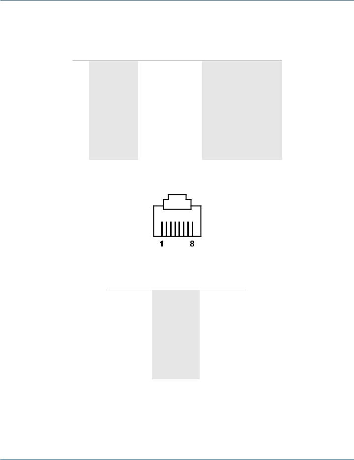
1.4 Ethernet Port (RJ-45)
Figure 1-1. RJ-45 connector pinout.
Table 1-2. RJ-45 connector pin assignment.
Pin Assignment |
568A Definition |
568B Definition |
|
|
|
1 |
Green-White |
Orange-White |
|
|
|
2 |
Green |
Orange |
|
|
|
3 |
Orange-White |
Green-White |
|
|
|
4 |
Blue |
Blue |
|
|
|
5 |
Blue-White |
Blue-White |
|
|
|
6 |
Orange |
Green |
|
|
|
7 |
Brown-White |
Brown-White |
|
|
|
8 |
Brown |
Brown |
|
|
|
You can choose either 568A or 568B pinning. To make a crossover cable, use 568A pinning at one end of a UTP cable and use 568B pinning at the other end of the UTP cable.
Page 8 |
724-746-5500 | blackbox.com |
LES301A user manual |
|
|

Chapter 1: Specifications
1.5 Power Terminal Block Connector
F.G. VINVIN+
Figure 1-2. Terminal block signals.
NOTE: VINand VIN+ can be reversed.
1.6 Buzzer/LED Message
1.6.1 Buzzer
“^”: Beep twice “=”: Beep off
|
Table 1-3. Buzzer message. |
|
|
Message |
Description |
|
|
^===^===^===^===^===^===^…(1sec) |
Watchdog problem, contact Black Box Technical Support* |
|
|
^^^^^^^^^^^^^^^^^^^^^^^^… |
Memory problem, contact Black Box Technical Support* |
|
|
^==^========^^ (5sec) |
Startup OK but AP firmware is disabled |
|
|
^==^========^^^ (5sec) |
Startup OK and AP firmware is enabled |
|
|
*Contact Black Box Technical Support at 724-746-5500 or info@blackbox.com.
1.6.2 LAN LED
|
Table 1-4. LAN LED. |
|
|
Message |
Description |
|
|
LED off |
Ethernet is disconnected |
|
|
LED is blinking green |
Data is transmitted at 100 Mbps on Ethernet |
|
|
LED is blinking orange |
Data is transmitted at 10 Mbps on Ethernet |
|
|
1.6.3 COM Port LED
|
|
Table 1-5. COM port LED message. |
|
|
|
|
|
|
Message |
Description |
|
|
|
|
|
|
LED off |
No data is being transmitted on COM port |
|
|
|
|
|
|
LED is blinking |
Data is being transmitted on COM port |
|
|
|
|
|
|
|
|
|
LES301A user manual
724-746-5500 | blackbox.com |
Page 9 |

Chapter 1: Specifications
1.6.4 RUN LED
|
Table 1-6. RUN LED. |
|
|
Message |
Description |
|
|
LED on |
Jumper JP1 Pin 1 and Pin 2 are short; this disables AP firmware in flash memory |
|
|
LED is blinking at the rate once every 0.5 sec |
AP firmware is running |
|
|
Page 10 |
724-746-5500 | blackbox.com |
LES301A user manual |
|
|
Chapter 2: Overview
2. Overview
2.1 Introduction
The LES301A Ethernet Serial Server is a gateway between Ethernet (TCP/IP) and RS-232 or RS-485/RS-422 communications. The information transmitted by the LES301A is transparent to both host computers (Ethernet) and devices (RS-232 or RS-485/RS-422). Data coming from the Ethernet (TCP/IP) is sent to the designated RS-232 or RS-485/RS-422 port and data being received from the RS-232 or RS-485/RS-422 port is sent to the Ethernet (TCP/IP) transparently.
In the computer integration manufacturing or industrial automation area, the Ethernet Serial Server is used to directly connect field devices to an Ethernet network. Terminal Server (the main control program that runs in LES301A) transforms whatever data is received from RS-232 or RS-485/RS-422 to a TCP/UDP port, then connects the devices to the Ethernet network via a single application program or multiple application programs.
Many control devices provide the ability to communicate with hosts through RS-232 or RS-485/RS-422; however, RS-232 or RS-485/RS-422 serial communication has its limitations. For example, it is hard to transfer data through a long distance. The LES301A can communicate with a remote device in the Intranet environment or even in the Internet, which increases the communication distance dramatically.
The LES301A has (1) RS-232/RS-485/RS-422 port (software selectable), (1) RJ-45 Ethernet and Watch-Dog Timer etc.
2.2 What’s Included
Your package should contain the following items. If anything is missing or damaged, contact Black Box Tech Support at 724-746-5500 or info@blackbox.com.
LES301A-KIT and LES301AE-KIT:
•(1) Ethernet Serial Server
•(1) CD-ROM containing configuration utility and this user manual in PDF format
•(2) wallmounting screws
•(1) printed quick-start guide
•(1) power adapter (PS012 for LES301A-KIT); (PS012E for LES301AE-KIT)
•(1) 3-pin Phoenix connector
2.3 Hardware Description
LES301A:
•(1) Ethernet Serial Server
•(1) CD-ROM containing configuration utility and this user manual in PDF format
•(1) printed quick-start guide
Optional Accessories:
•DIN Rail Kit (LES30X-DR)
•DB9 to TB5 Adapter (LES30X-TB5)
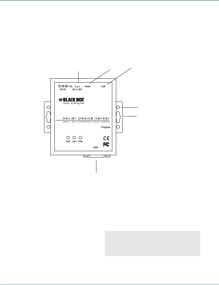
Figures 2-1 through 2-3 show the Ethernet Serial Server’s back panel, top panel, and front panel views. Table 2-1 describes its components. RJ-45 10-/100-Mbps
Ethernet port
Reset button
Figure 2-1. Back panel.
LES301A user manual |
724-746-5500 | blackbox.com |
Page 11 |
|
|

Chapter 2: Overview
|
Reset |
RJ-45 |
DC 9–30 V |
button |
10-/100-Mbps |
|
port |
|
|
|
|
|
|
DIN rail screw hole |
|
|
Wallmount screw hole |
DB9 male serial port |
|
|
Figure 2-2. Top panel.
|
|
|
|
|
|
|
|
|
|
|
|
|
|
|
|
|
|
|
|
|
|
|
|
|
|
|
|
|
|
DB9 male |
|
serial port |
|||
|
|
|||||||
|
|
|
Figure 2-3. Front panel. |
|||||
|
|
Table 2-1. Ethernet Serial Server components. |
||||||
|
|
|
|
|
|
|
||
Message |
|
|
Description |
|||||
|
|
|
|
|
|
|
||
LED off |
|
|
Ethernet is disconnected |
|||||
|
|
|
|
|
|
|
||
LED is blinking green |
|
|
Data is transmitted at 100 Mbps on Ethernet |
|||||
|
|
|
|
|
|
|
||
LED is blinking orange |
|
|
Data is transmitted at 10 Mbps on Ethernet |
|||||
|
|
|
|
|
|
|
|
|
2.4 Application Connectivity
TCP Server Mode: LES301A can be configured as a TCP server on a TCP/IP Network to wait for other applications (clients) in the host computer to establish a connection with the serial device. After the connection is established between the serial device and the host computer, data can be transmitted in both directions.
Computer
LES301A
Figure 2-4. TCP server mode. |
Serial bus |
PLC |
|
|
|
Page 12 |
724-746-5500 | blackbox.com |
LES301A user manual

Chapter 2: Overview
TCP Client Mode: LES301A can be configured as a TCP client on TCP/IP network to establish a connection with other applications (server) in the host computer actively. After the connection is established, data can be transmitted between the serial device and the host computer in both directions.
Remote control |
|
host |
LES301A |
Card reader
LES301A  Card
Card
reader
Figure 2-5. TCP Client mode.
UDP Mode: UDP is a faster but non-guaranteed datagram delivery protocol. LES301A can be configured as a UDP mode on TCP/ IP Network to establish a connection using unicast or multicast data from the serial device to one or multiple host computers. The opposite is also true.
Computers |
|
|
LES301A |
|
Ethernet |
|
|||
|
|
|
||
|
|
|
|
|
Serial bus |
Display |
|
Figure 2-6. UDP mode.
Tunneling Mode: In this mode, a serial connection with two or more LES301A units established sends data over TCP/IP Network. This extends the 50-foot (15-m) RS-232 distance limit.
LES301A
Touchscreen
Ethernet
Serial bus
LES301A |
PLC |
|
Figure 2-7. Tunneling mode.
LES301A user manual |
724-746-5500 | blackbox.com |
Page 13 |
|
|
Chapter 3: Hardware Setup
3. Hardware Setup
NOTE: Figures 2-1 through 2-3 in Chapter 2 show the LES301A unit’s back, top, and front views. NOTE: To reset the settings to the default value, press the LES301A‘s reset button.
Figure 3-1 shows the interfaces.
|
Reset |
RJ-45 |
|
|
10/100 Mbps |
||
|
button |
||
DC 9–30 V |
port |
||
|
|||
|
|
DIN rail screw hole |
|
|
|
Wallmount screw hole |
DB9 male serial port
Figure 3-1. LES301A interfaces.
3.1 LED Indicators
3.1.1 LAN LED
|
Table 3-1. LAN LED message. |
|
|
Message |
Description |
|
|
LED off |
Ethernet is disconnected |
|
|
LED is blinking green |
Data is transmitted at 100 Mbps on Ethernet |
|
|
LED is blinking orange |
Data is transmitted at 10 Mbps on Ethernet |
|
|
Page 14 |
724-746-5500 | blackbox.com |
LES301A user manual

Chapter 3: Hardware Setup
3.1.2 COM Port LED
|
Table 3-2. COM port LED message. |
|
|
Message |
Description |
|
|
Off |
No data is transmitted on the COM port |
|
|
LED is blinking |
Data is transmitted on the COM port |
|
|
3.1.3 RUN LED
|
Table 3-3. RUN LED message. |
|
|
Message |
Description |
|
|
On |
Jumper JP1 Pin 1 and Pin 2 are shorted to disable AP firmware running |
|
|
LED is blinking every 0.5 second |
AP firmware is running normally |
|
|
3.2 Installation Procedures (LES301A-KIT or LES301AE-KIT)
Step 1: Connect an LES301A to the included power supply (PS012 or PS012E) or to a 9–30 VDC source.
Step 2: Connect the LES301A to an Ethernet network. Use a standard straight-through Ethernet cable to connect to a hub/ switch, or connect it to a PC’s Ethernet port via a cross-over Ethernet cable.
NOTE: The PC must be in the same subnetwork as the LES301A.
Step 3: Connect the LES301A’s serial port to a serial device.
NOTE: You may need an adapter (LES30X-TB5) for RS-485 or RS-422 applications.
Step 4: Mount the LES301A to a wall or panel using the included mounting screws. Or, mount the unit to a DIN rail rack using the DIN Rail Kit (LES30X-DR).
NOTES: Disconnect the device from power source completely before installing and wiring the server.
Do not exceed the maximum allowable current of the power cord and common wire. If you don’t, the wire might overheat and cause serious damage to the connected and neighboring equipment.
The casing will be too hot to touch when operating in harsh environments. Please handle with care.
NOTE: Ground the LES301A properly through frame ground.
LES301A user manual |
724-746-5500 | blackbox.com |
Page 15 |
|
|
Chapter 4: Software Setup
4. Software Setup
The LES301A Ethernet Serial Server is shipped with default settings shown in Table 4-1.
|
Table 4-1. Default software settings. |
|
|
Property |
Default value |
|
|
IP address |
10.0.50.100 |
|
|
Gateway |
10.0.0.254 |
|
|
Subnet mask |
255.255.0.0 |
|
|
User name |
admin |
|
|
Password |
Null (leave it blank) |
|
|
COM 1 |
9600, None, 8, 1, No flow control, buffer disabled, packet delimiter timer 2 ms |
|
|
Link 1 |
Type: TCP server, listen port 4660, filter=0.0.0.0, virtual COM disabled |
|
|
SysName of SNMP |
name |
|
|
SysLocation of SNMP |
location |
|
|
SysContact of SNMP |
contact |
|
|
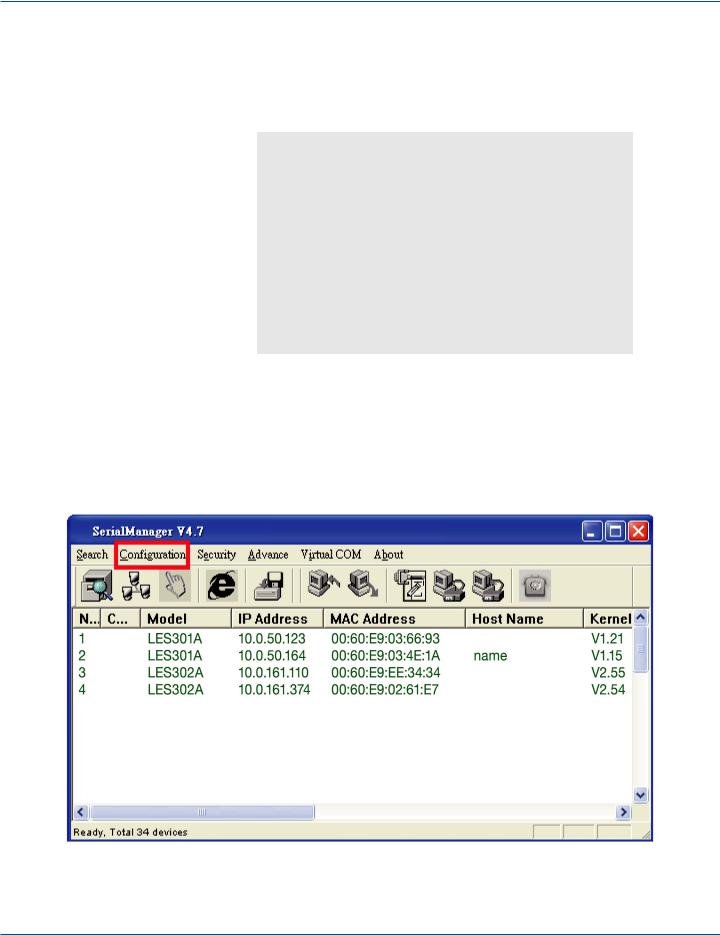
4.1 Configuration by SerialManager
4.1.1 Static IP
Use SerialManager that’s included on the product CD to configure the LES301A’s network parameters. Click on the “Configuration” button (see Figure 4-1) then give it static IP information (see Figure 4-2.)
Figure 4-1. Configure using SerialManager.
Page 16 |
724-746-5500 | blackbox.com |
LES301A user manual |
|
|

Chapter 4: Software Setup
Figure 4-2. Static IP setup dialog window.
4.1.2 Auto IP (Dynamic IP)
A DHCP server can automatically assign the IP address and network settings. The LES301A supports the DHCP function. By default, the DHCP function on the LES301A is disabled; you can use SerialManager software to search network information automatically by following these steps:
1.Execute SerialManager (Figure 4-1).
2.Click on the IP address of the LES301A in SerialManager.
3.Click on the “Config” button, and the dialog window will pop up (Figure 4-2).
4.Check ”DHCP (Obtain an IP automatically)” (Figure 4-3).
5.Click on the “Config Now” button (The LES301A will restart and get its IP from the DHCP server automatically.)
Figure 4-3. SerialManager auto IP dialog window.
LES301A user manual |
724-746-5500 | blackbox.com |
Page 17 |
|
|

Chapter 4: Software Setup
4.2 Configuration by Telnet Utility
You can use the Telnet utility to change configuration settings of the LES301A.
4.2.1 Log into the System
Open the MS-DOS® command prompt window.
Telnet to the LES301A using the command “Telnet IP_address.” (For example: Input Telnet 10.0.50.100 in the MS-DOS command prompt window). After you Telnet to LES301A, the system prompts for a password; the default password is blank. (Figure 4-4).
Figure 4-4. Log into the system.
NOTE: Press the LES301A default button to reset the password to the default value.
After verifying the password, the following terminal screen appears (see Figure 4-5).
Figure 4-5. Main menu.
NOTES: If the LES301A does not receive any command within one minute, Telnet will be terminated automatically.
The networking parameter changes will take effect only when you exit and restart the LES301A.
Select “1” from “Input choice and enter (0–4):” to enter the overview page as shown in Figure 4-6.
Page 18 |
724-746-5500 | blackbox.com |
LES301A user manual |
|
|

Chapter 4: Software Setup
Figure 4-6. Overview.
This page gives you general information about the LES301A, including IP and MAC address, SNMP information, kernel and AP information, and connection status of the device.
LES301A user manual |
724-746-5500 | blackbox.com |
Page 19 |
|
|

Chapter 4: Software Setup
4.2.2 Networking
Select “2” from “Input choice and enter (0–4):” to enter the Networking page (see Figure 4-7).
Figure 4-7. Network settings.
This page allows you to change the LES301A’s network settings, including IP address, subnet mask, gateway IP address, and
SNMP information.
NOTE: Any setting change made on this page won’t take effect until you restart the device.
NOTE: Press the “ESC” key to return to the previous menu.
Page 20 |
724-746-5500 | blackbox.com |
LES301A user manual |
|
|

Chapter 4: Software Setup
4.2.3 Change the Password
1. Select “3” from “Input choice and enter (0–4):” and the following screen appears (see Figure 4-8).
Figure 4-8. Change the password.
2.To change the password, type the old password in the “Please input old password” field, then type the new password in the “Please input new password” and the “Please verify new password” fields.
NOTE: Press the product’s default key to reset the password to the default value.
4.2.4 COM1 Setup
Select “4” from “Input choice and enter (0–4):” The following screen appears (see Figure 4-9).
Figure 4-9. COM1 setup.
LES301A user manual |
724-746-5500 | blackbox.com |
Page 21 |
|
|
 Loading...