


G.703
CUSTOMER
SUPPORT
INFORMATION
Order toll-free in the U.S.: Call 877-877-BBOX (outside U.S. call 724-746-5500)
FREE technical support 24 hours a day, 7 days a week: Call 724-746-5500 or fax 724-746-0746
Mailing address: Black Box Corporation, 1000 Park Drive, Lawrence, PA 15055-1018
Web site: www.blackbox.com • E-mail: info@blackbox.com
DECEMBER 1995
IC713A
IC713AE
G.703 Codirectional Converter
DIG ANA
G.703 Codirectional Converter
PWR
TD
RD
LOS
TEST

1
FCC STATEMENT
FEDERAL COMMUNICATIONS COMMISSION
AND
INDUSTRY CANADA
RADIO FREQUENCY INTERFERENCE STATEMENTS
This equipment generates, uses, and can radiate radio-frequency energy, and if not
installed and used properly, that is, in strict accordance with the manufacturer’s
instructions, may cause interference to radio communication. It has been tested
and found to comply with the limits for a Class A computing device in accordance
with the specifications in Subpart B of Part 15 of FCC rules, which are designed to
provide reasonable protection against such interference when the equipment is
operated in a commercial environment. Operation of this equipment in a
residential area is likely to cause interference, in which case the user at his own
expense will be required to take whatever measures may be necessary to correct
the interference.
Changes or modifications not expressly approved by the party responsible
for compliance could void the user’s authority to operate the equipment.
This digital apparatus does not exceed the Class A limits for radio noise emission from
digital apparatus set out in the Radio Interference Regulation of Industry Canada.
Le présent appareil numérique n’émet pas de bruits radioélectriques dépassant les limites
applicables aux appareils numériques de la classe A prescrites dans le Règlement sur le
brouillage radioélectrique publié par Industrie Canada.

2
G.703 CODIRECTIONAL CONVERTER
NORMAS OFICIALES MEXICANAS (NOM)
ELECTRICAL SAFETY STATEMENT
INSTRUCCIONES DE SEGURIDAD
1. Todas las instrucciones de seguridad y operación deberán ser leídas antes de
que el aparato eléctrico sea operado.
2. Las instrucciones de seguridad y operación deberán ser guardadas para
referencia futura.
3. Todas las advertencias en el aparato eléctrico y en sus instrucciones de
operación deben ser respetadas.
4. Todas las instrucciones de operación y uso deben ser seguidas.
5. El aparato eléctrico no deberá ser usado cerca del agua—por ejemplo, cerca
de la tina de baño, lavabo, sótano mojado o cerca de una alberca, etc..
6. El aparato eléctrico debe ser usado únicamente con carritos o pedestales que
sean recomendados por el fabricante.
7. El aparato eléctrico debe ser montado a la pared o al techo sólo como sea
recomendado por el fabricante.
8. Servicio—El usuario no debe intentar dar servicio al equipo eléctrico más allá
a lo descrito en las instrucciones de operación. Todo otro servicio deberá ser
referido a personal de servicio calificado.
9. El aparato eléctrico debe ser situado de tal manera que su posición no
interfiera su uso. La colocación del aparato eléctrico sobre una cama, sofá,
alfombra o superficie similar puede bloquea la ventilación, no se debe colocar
en libreros o gabinetes que impidan el flujo de aire por los orificios de
ventilación.
10. El equipo eléctrico deber ser situado fuera del alcance de fuentes de calor
como radiadores, registros de calor, estufas u otros aparatos (incluyendo
amplificadores) que producen calor.
11. El aparato eléctrico deberá ser connectado a una fuente de poder sólo del
tipo descrito en el instructivo de operación, o como se indique en el aparato.

3
NOM STATEMENT
12. Precaución debe ser tomada de tal manera que la tierra fisica y la polarización
del equipo no sea eliminada.
13. Los cables de la fuente de poder deben ser guiados de tal manera que no
sean pisados ni pellizcados por objetos colocados sobre o contra ellos,
poniendo particular atención a los contactos y receptáculos donde salen del
aparato.
14. El equipo eléctrico debe ser limpiado únicamente de acuerdo a las
recomendaciones del fabricante.
15. En caso de existir, una antena externa deberá ser localizada lejos de las lineas
de energia.
16. El cable de corriente deberá ser desconectado del cuando el equipo no sea
usado por un largo periodo de tiempo.
17. Cuidado debe ser tomado de tal manera que objectos liquidos no sean
derramados sobre la cubierta u orificios de ventilación.
18. Servicio por personal calificado deberá ser provisto cuando:
A: El cable de poder o el contacto ha sido dañado; u
B: Objectos han caído o líquido ha sido derramado dentro del aparato; o
C: El aparato ha sido expuesto a la lluvia; o
D: El aparato parece no operar normalmente o muestra un cambio en su
desempeño; o
E: El aparato ha sido tirado o su cubierta ha sido dañada.

4
G.703 CODIRECTIONAL CONVERTER
TRADEMARKS USED IN THIS MANUAL
Any trademarks mentioned in this manual are acknowledged to be the property of the
trademark owners.

5
CONTENTS
Contents
Chapter Page
1. Specifications ...................................................................................................6
2. Introduction ....................................................................................................8
2.1 Functional Description ......................................................................8
2.2 Timing Theory ...................................................................................9
2.2.1 CCITT G.703 Signalling ..........................................................9
2.2.2 G.703 Codirectional Timing..................................................10
2.2.3 Tail-End Clocking ..................................................................14
2.2.4 G.703 Codirectional Rules.....................................................14
2.3 Rate-Conversion Rules .....................................................................16
2.4 Physical Description .........................................................................16
3. Installation ....................................................................................................17
3.1 Unpacking .......................................................................................17
3.2 Site Requirements...............................................................................17
3.3 Setting Jumpers...................................................................................17
3.3.1 Overview...................................................................................17
3.3.2 The Jumper-Setting Procedure ..............................................20
3.4 Installation in 19-Inch Racks..............................................................20
3.4.1 Overview .................................................................................20
3.4.2 Installing a Single Unit in a 19-Inch Rack ............................21
3.4.3 Installing Two Units in a 19-Inch Rack.................................22
3.5 Connecting Power and Data Cables ..................................................24
3.5.1 Power Connection...................................................................25
3.5.2 G.703 LINE Connection .........................................................25
3.5.3 DTE Connection .....................................................................25
3.5.4 Async Secondary-Channel Connection..................................26
4. Operation.......................................................................................................27
4.1 Front-Panel Controls and LEDs .........................................................27
4.2 Operating Instructions .......................................................................29
4.2.1 Turn-On Procedure ................................................................29
4.2.2 Activating Loops......................................................................29
4.2.3 Turn-Off Procedure ................................................................29
4.3 Diagnostic Loops.................................................................................29
Appendix: Pinouts .............................................................................................31

6
G.703 CODIRECTIONAL CONVERTER
1. Specifications
G.703 I
NTERFACE
:
Type — Codirectional 64-kbps
Line — 4-wire, 19- to 26-gauge
Range — Up to 800 meters (1⁄2 mile) over 24-gauge wire
Impedance — 120 ohms nominal
Balance — Better than 45 dB (up to 256 kHz)
Better than 35 dB (up to 384 kHz)
Return Loss — Better than 20 dB (up to 128 kHz)
Better than 14 dB (up to 384 kHz)
“Pulse” Amplitude — 1.0 V nominal
“Zero” Amplitude — 0 V ± 0.1 V max
Clock Frequency — 64 kHz
Frequency Tracking — ± 500 ppm
Connector — 5-screw terminal block
Jitter Performance — To G.823 requirements
D
ATA-COMMUNICATIONSINTERFACE
:
Type — CCITT V.35; CCITT X.21/V.11;
CCITT V.36/V11 (EIA RS-449/RS-422);
EIA RS-530
Data Rate — 64, 56, or 48 kbps, user-selectable
Spare Bandwidth — (at 56 or 48 kbps) “1’s” density bit stuffing as per
CCITT V.110; additional synchronous channel at
1200 bps; transfer of RTS to DCD control signal,
end-to-end
Connector — DB25 female

7
CHAPTER 1: Specifications
D
ATA
-C
OMMUNICATIONSCONTROLSIGNALS
:
Electrical — CCITT V.28 (unbalanced, as per V.35)
Functional — DCD, 64 kbps: ON when Rx pair contains required
violations, OFF when the Rx pair does not
contain required violations;
DCD, 48 or 56 kbps: When the Rx pair contains
the required violations, the DCD signal reflects
the state of the remote RTS; DCD is always OFF
when no violations are detected;
CTS output: ON after RTS ON, with delay; OFF
when RTS OFF, or during Loss of Signal
condition;
DSR output: ON (+V) when power is available
Clock Source — From G.703 Receive pair (LBT), from DCE (EXT),
or from internal source (INT), user-selectable
Data Polarity — Normal (MARK = “0”) or inverted (MARK = “1”),
user-selectable
O
THERPHYSICALSPECIFICATIONS
:
Indicators — (5) Front-mounted LEDs: Power (PWR), Receive
Data (RD), Transmit Data (TD), Loss of Signal
(LOS), and Test (TEST)
Temperature — 32 to 122°F (0 to 50°C)
Humidity — Up to 95% non-condensing
MTBF — 110,000 hours
Power — Directly from outlet:
Voltage: 115 VAC (IC713A) or 230 VAC (IC713AE);
Frequency: 47 to 63 Hz;
Consumption: 25 watts;
(A –48-VDC version (IC713A-48) of the Converter is
also available; call your supplier for details)
Size — 1.8"H x 7.6"W x 9.5"D (4.6 x 19.3 x 24.1 cm)
Weight — 3.7 lb (1.7 kg)

8
G.703 CODIRECTIONAL CONVERTER
2. Introduction
2.1 Functional Description
The G.703 Codirectional Converter converts the CCITT G.703 codirectional
interface to standard data-communication interfaces. The Converter can
perform two conversions:
• Electrical Conversion — from G.703 to CCITT V.35, V.36/V.11
(EIA RS-449/422), X.21/V.11, or EIA RS-530
• Data-Rate Conversion — from 64 kbps to 48 or 56 kbps, when required
The electrical and rate conversions enable you to connect DCE devices to
PCM transmission equipment.
The Converter is field-selectable for either V.35 or V.11 electrical standards.
The interface connector for either V.35 or V.11 is a 25-pin D-type (“DB25”)
connector. If you select V.11, you’ll need the appropriate cable to implement
the V.36, X.21, or EIA RS-530 standard.
Operating full-duplex at a transmission rate of 64 kbps, the Converter has
a range of up to 800 meters (1⁄2
mile) from the PCM equipment. The unit’s
receive-timing source is the recovered clock from the CCITT G.703 receive
pair. You can
set a jumper to select any one of these transmit-timing sources:
• Recovered clock from the received pair;
• External timing from the V.11 or V.35 digital interface; or
• Internal timing (used only for testing and diagnostics).
Two internal 16-bit buffers accommodate the difference in clocking phase.
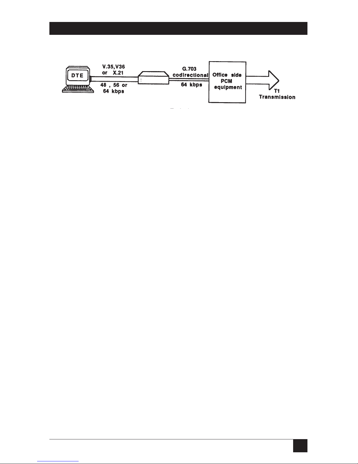
Figure 2-1 below shows a typical application of the G.703 Codirectional
Converter. The Converter can act as a data-rate adapter, allowing you to
connect DTEs running at 48 or 56 kbps to a 64-kbps G.703-interface line.
At 48 or 56 kbps, you can set another jumper to select any one of these
ways to use the extra bandwidth:
• To guarantee the satisfaction of the “ones density” requirement,
by placing a “1” after every seven bits.
• To pass a control signal end-to-end
• As a 1200-bps asynchronous secondary sub-channel for connecting
additional DTE units over the same link.
9
CHAPTER 2: Introduction
Figure 2-1. Typical G.703 Codirectional Converter application.
The Converter also provides diagnostic capabilities with analog and digital
loopbacks. Both loops are activated by the front-panel pushbuttons. You can
use the Converter’s front-panel LEDs to continuously monitor the main
channel’s activity and synchronization.
2.2 Timing Theory
2.2.1 CCITT G.703 S
IGNALING
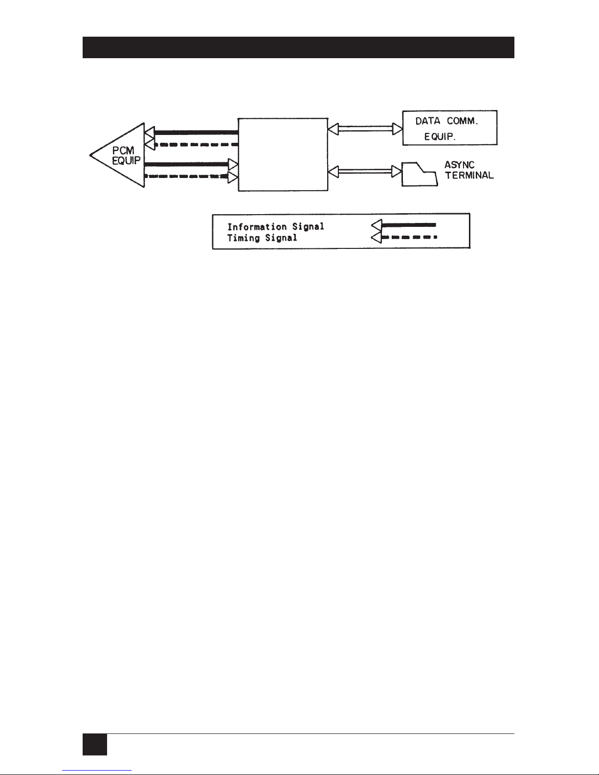
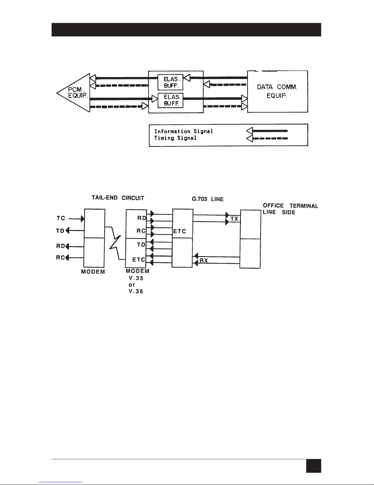
The CCITT G.703 codirectional signal is made up of two balanced signals:
The receive and transmit signals carry timing and data information.
The clock signal associated with each direction of transmission travels
in the same direction as the data signal (see Figure 2-2).
G.703
Codirectional
Converter
10
G.703 CODIRECTIONAL CONVERTER
Figure 2-2. G.703 Codirectional Converter signaling.
2.2.2 G.703 C
ODIRECTIONALTIMING
The G.703 Codirectional Converter can support virtually all timing options
that you might need, as described and illustrated in this section.
G.703 Receive Timing Used for G.703 Transmit Timing
When G.703 receive timing is used for G.703 transmit timing, three timing
options for the data-communication side, associated with the loopback timing
(LBT) on the G.703 side, are available:
• Receive Clock and Transmit Clock are both outputs from the Converter,
which serves as a DCE (see Figure 2-3).
• Receive Clock and Transmit Clock are both inputs to the Converter
(with X.21 interface only), which serves as a DTE (see Figure 2-4).
• Receive Clock is an output from the Converter, while Transmit Clock
is an input to the Converter from an external DCE, for connection to
a tail circuit (see Figure 2-5).
G.703
Codirectional
Converter

11
CHAPTER 2: Introduction
Figure 2-2. G.703 Codirectional Converter signaling.
Figure 2-3. LBT-DTE Connection.
Figure 2-4. LBT-DCE21 Connection.
G.703
Codirectional
Converter
G.703 Codirectional
Converter
G.703 Codirectional
Converter
12
G.703 CODIRECTIONAL CONVERTER
Figure 2-5. LBT-DCE Connection.
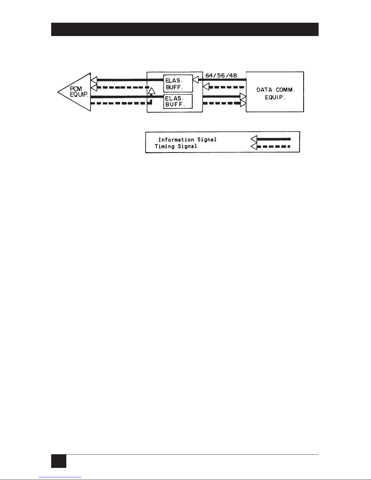
Transmit-Clock Timing Mode
When you use the external transmit clock on the data-communications side
for G.703 transmit timing, there is complete independence, within the G.703
Codirectional Converter, between the receive and the transmit directions of
transmission. Figure 2-6 shows this timing mode.
Internal-Clock Timing Mode
The Converter’s internal oscillator is usually used as the source for G.703
transmit timing for testing purposes only, but can also be used with systems
that do not have a clock source. Figure 2-7 shows this timing mode.
G.703 Codirectional
Converter
13
CHAPTER 2: Introduction
Figure 2-6. Transmit Clock Timing Mode.
Figure 2-7. Internal Clock Timing Mode.
G.703 Codirectional
Converter
G.703 Codirectional
Converter
 Loading...