

Page 1

P4M900-M7 FE/P4M890-M7 FE BIOS Setup
BIOS Setup ................................................................................................ 1
1 Main Menu ............................................................................................. 3
2 Standard CMOS Features..................................................................... 6
3 Advanced BIOS Features ...................................................................... 8
4 Advanced Chipset Features................................................................. 16
5 Integrated Peripherals......................................................................... 20
6 Power Management Setup................................................................... 26
7 PnP/PCI Configurations...................................................................... 31
8 PC Health Status .................................................................................. 34
9 Performance Booster Zone.................................................................. 37
i
Page 2

P4M900-M7 FE/P4M890-M7 FE
BIOS Setup
Introduction
The purpose of this manual is to describe the settings in the Phoenix-Award™
BIOS Setup program on this motherboard. The Setup program allows users to
modify the bas ic system configuration and save these settings to C MOS RAM.
The power of CMOS RAM is supplied by a battery so that it retains the Set up
info rmation when t he power is t urned off.
Basic Input-Output Sys tem ( BIOS) d et ermine s what a computer c an do without
accessing programs from a disk. This system controls most of the input and
outp ut de vices suc h as keyboard, mouse, serial ports and dis k drives. BIOS
activates at the first stage of the booting proc ess, loading and executing the
operating system. Some additional features, s uch as virus and password
protection or chipset fine-tuning options are also included in BIOS.
The rest of this manual will to guide you through the options and settings in
BIOS Setup.
Plug and Play Support
This PHO ENIX-AW ARD BIOS suppo rts t he Plug and Play Version 1. 0A
specification.
EPA Green PC Support
This PHOENIX-AWARD BIOS supports Version 1.03 of the EPA Green PC
specification.
APM Support
This PHOENIX-AWARD BIOS suppo rts Vers ion 1.1& 1. 2 of t he Advanc ed
Power Management (APM) specification. Power management features are
implemented via the System Management Interrupt (SMI). Sleep and Suspend
power management modes are supported. Power to the hard disk drives and
video monito rs can also be managed by this PHOENIX-AWARD BIOS.
ACPI Support
Phoenix-Award ACPI BIOS support Version 1.0b of Advanced Configuration
and Power interface specification (ACPI). It provides ASL code for power
management and device configuration capabilit ies as defined in the ACPI
specification, developed by Microsoft, Intel and Toshiba.
1
Page 3

P4M900-M7 FE/P4M890-M7 FE
PCI Bus Support
This PHO ENI X-AWARD BIOS a lso s uppo rts Vers ion 2.3 o f the Intel PCI
(Peripheral Component Interconnect) local b us specific atio n.
DRAM Support
DDR2 S DRAM (Double Data Rate S ynchronous DRAM) is supported.
Supported CPUs
This PHOENIX-AWARD BIOS supports the Intel CPU.
Using Setu p
Use the arrow keys to high light items in most of the plac e, press <Enter> to
select, use the <PgUp> and <PgDn> keys to change entries, press <F1> for help
and press <Esc> to quit. The following table p rovides more detail about how to
navigate in t he Setup p rogram by using the keyboard.
Keystroke Function
Up arrow Move to p revio us i tem
Down arrow Move to next i tem
Left arro w Move to the item o n the left (menu bar )
Right arrow Move to t he item o n the ri ght (me nu bar)
Move Enter Move to the item you desired
PgUp key Inc rease the numeric value or make changes
PgDn key Decrease the numeric value or make changes
+ Key Increase the numeric value or make changes
- Key Decrease the numeric value or make c hanges
Esc key Main Menu – Quit and not save changes into CMOS
F1 key General help o n Setup navigation keys
F5 key Load previous values from CMOS
F7 key Load the optimized defaults
F10 key Save all the CMOS changes and exit
Status Page Setup Menu and Optio n Page Setup Me nu – Exit
Current page and re turn to Main Menu
2
Page 4
P4M900-M7 FE/P4M890-M7 FE
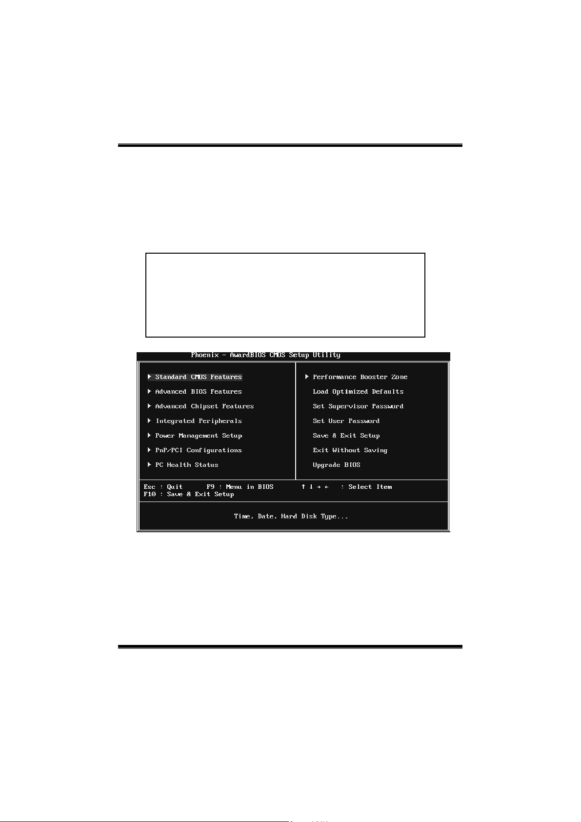
1 Main Menu
Onc e you enter Phoenix-Award BIOS™ CMOS Setup Utility, the Main Menu
will appear o n the screen. The Main Menu allows you to s elect from several
setup functions. Use the arrow keys to select among the items and press <Enter>
to accept and enter the sub-menu.
!! WARNING !!
For better system performance, the BIOS firmware is being
continuo us ly updated. The BIOS in formatio n describ ed in
this manual (Figure 1, 2, 3, 4, 5, 6, 7, 8, 9) is fo r yo ur
reference only. The actual BIOS information and settings on
board may be slightly different from this manual.
Figure 1: Main Menu
Stan dar d CMOS Fe atures
This submenu contains industry standard configurable options.
Advanced BIOS Features
This submenu a llows yo u to configure advanced feat ures o f th e BIOS.
3
Page 5

P4M900-M7 FE/P4M890-M7 FE
Advanced Chipset Features
This submenu allows you to configure special chipset features.
Integrated Peripherals
This s ub menu allo ws you to configure certain IDE hard d rive optio ns and
Programmed Input/ Output features.
Power Management Setup
This submenu allows you to configure the power management features.
PnP/PCI Configurati ons
This submenu allows you to configure certain “Plug and Play” and PCI options.
PC Health Status
This submenu a llo ws yo u to monitor the hard ware of your syste m.
Performance Booster Zone
This submenu allows you to change CPU Vcore Voltage and CPU/PCI clock.
(However, we suggest you to use the default setting. Changing the voltage and
cloc k imp rop erly may d amage th e CPU or M/B!)
Load Optimized Defaults
This selection allo ws you to reload the BIOS when problem occurs during
system booting sequenc e. These configurations are factory settings optimized
for this system. A confirmation message will be disp layed before defaults are
set.
Set Supervisor Password
Setting the sup ervisor password wil l prohibit everyone except the supervisor
from making changes using the CMOS Setup Utility. You will b e prompted with
to ent er a password.
4
Page 6

P4M900-M7 FE/P4M890-M7 FE
Set User Password
If the Supervisor P ass word is not set, then the User P ass word will function in
the same way as the Supervisor Password. If the Supervisor Password is set and
the User P ass word is set, the “User” wil l o nly be able to view configurations but
will not be able to c hange them.
Save & Exit Setup
Save all configuration c hanges to CMOS (memory) and exit setup. Confirmation
message will be displayed before proceeding.
Exit Without Saving
Abandon all changes made during the current session and exit setup.
Confirmation message will be displayed before proceeding.
Upgrade BIOS
This submenu allows you to upgrade bios.
5
Page 7

P4M900-M7 FE/P4M890-M7 FE
2 Standard CMOS Features
The items in Standard CMOS Setup Menu are divided into several categories.
Each category includ es no, one or mo re than one set up items. Us e the arrow
keys to highlight the ite m and then use the<P gUp> or <PgDn> keys to se lec t the
value you want in each item.
Figure 2: Standard CMOS Setup
Main Menu Selections
This table shows the items and the available options on the Main Menu.
Item Options Description
Date mm : dd : yy
Time hh : mm : ss
IDE Channel 0 Master
IDE Channel 0 Slave
Options are in its sub
menu.
Options are in its sub
menu.
6
Set the system date. Note
that the ‘Day’ automatically
changes when you set the
date.
Set the system internal
clock.
Press <Enter> to enter the
sub menu of detailed
options
Press <Enter> to enter the
sub menu of detailed
options.
Page 8

P4M900-M7 FE/P4M890-M7 FE
Item Options Description
IDE Channel 1 Master
IDE Channel 1 Slave
Drive A
Drive B
Halt On
Base Memory N/A
Extended Memory N/A
Total Memory N/A
Options are in its sub
Options are in its sub
360K, 5.25 in
1.2M, 5.25 in
720K, 3.5 in
1.44M, 3.5 in
2.88M, 3.5 in
All Errors
No Errors
All, but Keyboard
All, but Diskette
All, but Disk/ Key
menu.
menu.
None
Press <Enter> to enter the
sub menu of detailed
options.
Press <Enter> to enter the
sub menu of detailed
options.
Select the type of floppy
disk drive installed in your
system.
Select the situation in which
you want the BIOS to stop
the POST process and
notify you.
Displays the amount of
conventional memory
detected during boot up.
Displays the amount of
extended memory detected
during boot up.
Displays the total memory
available in the system.
7
Page 9
P4M900-M7 FE/P4M890-M7 FE
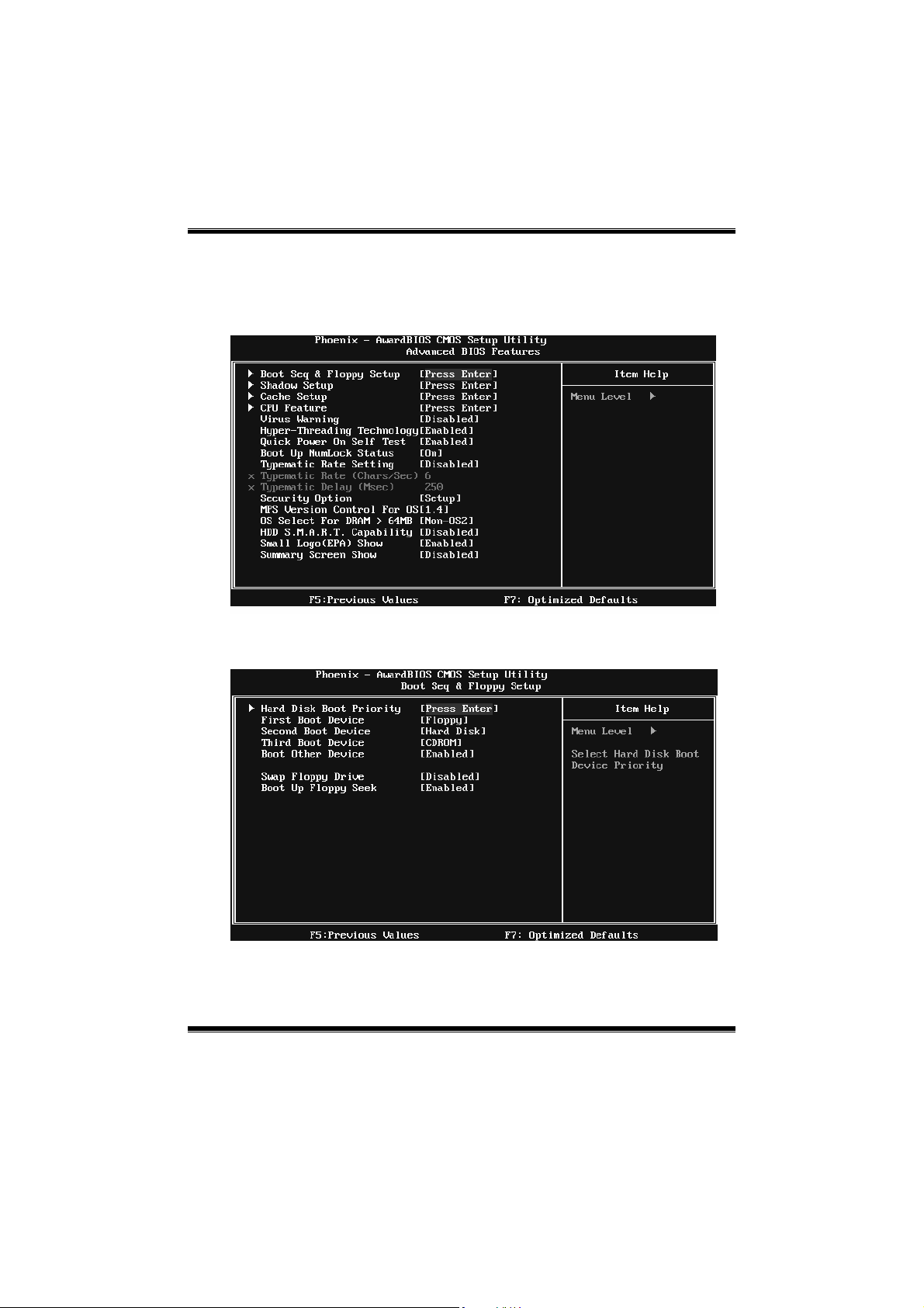
3 Advanced BIOS Features
Figure 3: Advanced BIOS Setup
Boot Seq & Floppy Setup
This item allows you to setup boot sequence & Floppy.
8
Page 10
P4M900-M7 FE/P4M890-M7 FE
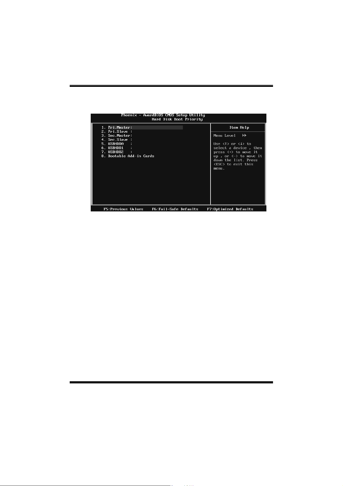
Hard Disk Boot Priority
The BIOS will attempt to arrange the Hard Disk boot sequence automatically.
You can change the Hard Disk booting sequence here.
The Choices: Pri. Master, Pri. Slave, Sec. Master, Sec. Slave, USB HDD0, USB
HDD1, US B HDD2, and Bootable Add-in Cards.
First/Second/Third Boot Device
The BIOS will attempt to load the operating system in this order.
The Choices: Floppy, LS120, Hard Disk, CDROM, ZIP100, USB-FDD,
USB-ZIP, USB-CDROM, LAN, Disabled.
Boot Other Device
When enabled, BIOS will try to load the operating system from other device
when it failed to load from the three devices above.
The Choices: Enabled (default), Disab led
Swap Floppy Drive
For systems with two floppy drives, this option allows you to swap logical
drive assignments.
The Choices: Disabled (default), Enabled.
9
Page 11
P4M900-M7 FE/P4M890-M7 FE
Boot Up Floppy Seek
When enabled, System will test the floppy drives to determine if they have 40
or 80 tracks during boot up. Disabling this option reduces the time it takes to
boot-up.
The Choices: Enabled (default), Disabled.
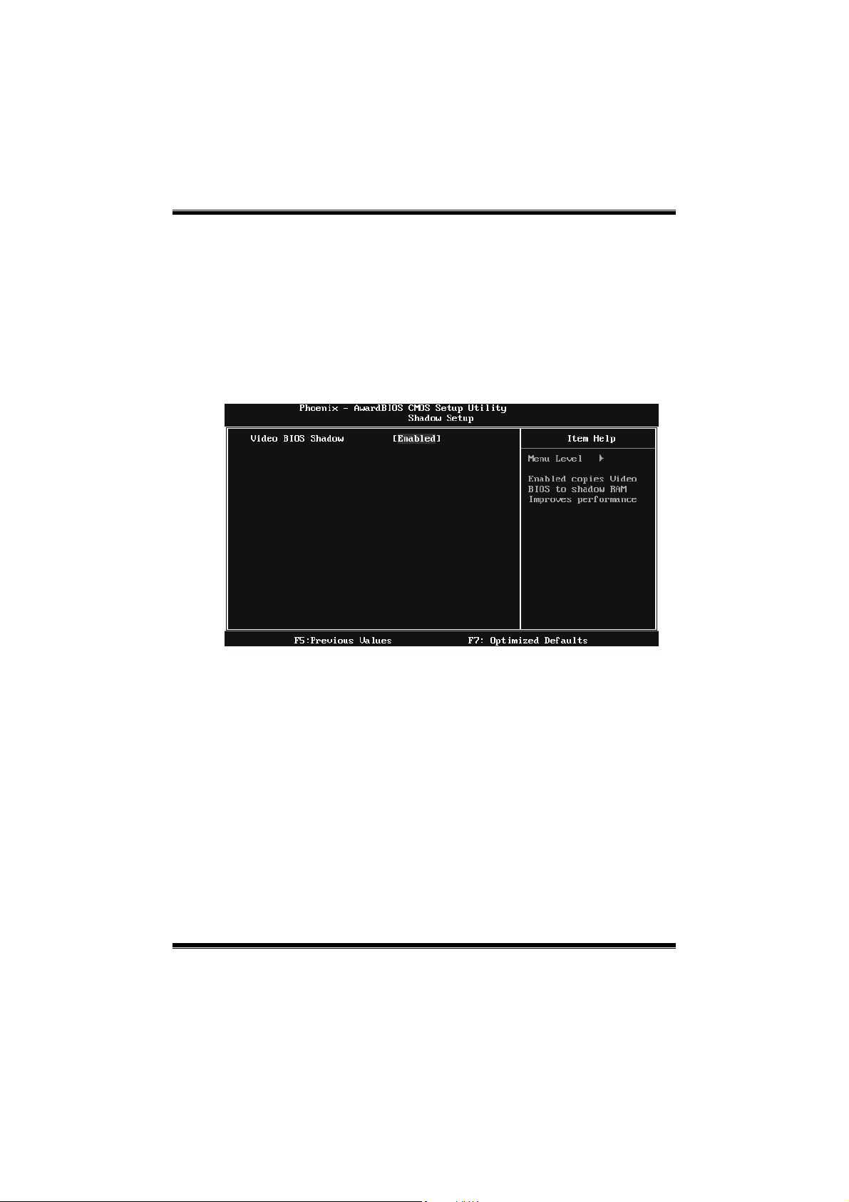
Shadow Setup
This item allows you to setup c ac he & s hadow setup.
Figure 3.2: Shadow Setup
Video BIOS Shadow
Determines whether video BIOS will be copied to RAM for faster execution or
not.
Enable d (default) Optional ROM is enabled.
Disabled Optional ROM is disabled.
10
Page 12
P4M900-M7 FE/P4M890-M7 FE
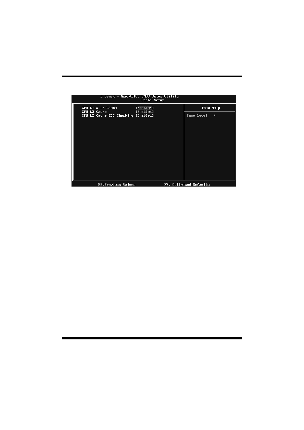
Cache Setup
CPU L1 & L2 Cache
Depending on the CPU/chipset in use, you may be able to increase memory
ac cess tim e with this opt ion .
Enable d (default) Enable cache.
Disabled Disable cache.
CPU L3 Cache
Depending on the CPU/chipset in use, you may be able to increase memory
ac cess tim e with this opt ion .
Enable d (default) Enable cache.
Disabled Disab le cache.
CPU L2 Cache ECC Checking
This item allows you to enable/disable CPU L2 Cache ECC Checking.
The Choices: Enabled (default), Disabled.
11
Page 13
P4M900-M7 FE/P4M890-M7 FE
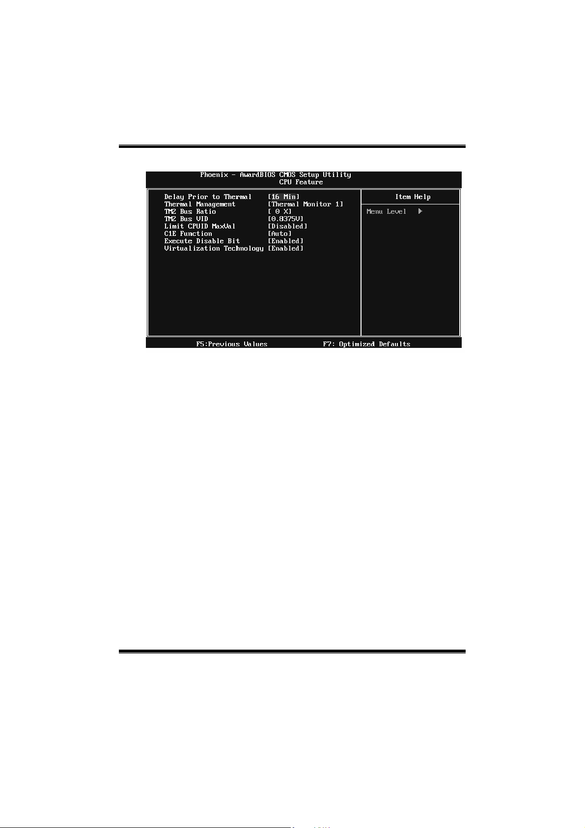
CPU Feature
Delay Prior to Thermal
Set this item to enable the CPU Thermal function to engage after the specified
time.
The Choices: 4 Min, 8 Min, 16Min (default), 32 Min.
Thermal Management
This option allows you to select the way to control the “Thermal Management.”
The Choices: Thermal Monitor 1 (default), Thermal Monitor 2.
TM2 Bus Ratio
This option represents the frequency (bus ratio) of the throttled performance
st ate t hat w ill be init iated whe n the o n-die sensor dete cts temper atu re increa se.
Min= 0, Max= 255 ; Key in a DEC number.
The Choices: 0 X (default)
TM2 Bus VID
This option represents the voltage of the throttled performance state that will be
initia ted when the o n-die sensor detects temp eratur e increase.
The Choices: 0.8375V (default), 0.8375-1.6000.
12
Page 14

P4M900-M7 FE/P4M890-M7 FE
Li mi t CPUID Max Val
Set Limit CPUID MaxVal to 3, it should be “Disabled” for Windows XP.
The Choices: Disabled (defa ult), Enabled.
C1E Function
This item allows you to configure the Enhanced Halt State (C1E) function,
which may reduce the power consumption of your system when the system is
id le.
The Choices: Auto (default), Disabled.
Execu te Disable Bit
This item allows you to configure the Execute Disabled Bit function, which
protects your system from buffer overflow attacks.
The Choices: Enabled (default), Disabled.
Virtualization Technology
Virtualization Technology can virtually separate your system resource into
several parts, thus enhance the performance when running virtual machines or
mult i inte rfa ce syst ems.
The Choices: Enabled (default), Disabled.
Virus Warning
This option allows you to choose the VIRUS Warning feature that is used to
protect the IDE Hard Disk boot sector. If this function is enabled and an attempt
is made to write to the boot sector, BIOS will disp lay a warning message o n the
screen and sound an alarm beep.
Disabled (default) Virus protectio n is disabled.
Enabled Virus protection is activated.
Hyper-Threading Technology
This option allows you to enab le or d isab led Hyper-T hread ing Technology.
“Enabled” for Windows XP and Linux 2.4.x (OS optimized for
Hyper-Threading Technology). “Disable” for other OS (OS not optimized for
Hyper-Threading Technology).
The Choices: Enabled (default), Disabled.
13
Page 15

P4M900-M7 FE/P4M890-M7 FE
Quick Power On Self Test
Enabling this option will cause an abridged version of the Power On Self-Test
(POS T) to execut e after you power up the computer.
Disabled Normal POST.
Ena bled (default) Enable quick POST.
Boot Up NumLock Status
Selec ts the NumLock St ate after the s ystem switc hed on.
The Choices:
On (d efault) Nump ad is number keys.
Off Numpad is arrow keys.
Typematic Rate Setting
When a key is held down, the keystroke will repeat at a rate determined b y the
keyboard controller. When enabled, the typematic rate and typematic delay can
be configured.
The Choices: Disabled (default), Enabled.
Typematic Rate (Chars/Sec)
Sets the ra te at whic h a keys troke is repea ted when you hold the key down.
The Choices: 6 (default), 8, 10, 12, 15, 20, 24, 30.
Typematic Delay (Msec)
Sets the delay time after the key is held do wn before it begins to rep eat the
keystroke.
The Choices: 250 (default), 500, 750, 1000.
Security Option
This option will enable only individ uals with p ass words to bring the system
online and/or to use the CMOS Setup Utility.
System: A pass word is required for the system to boot and is also
required to access the Setup Utility.
Setup (def ault): A pass word is required to access the Setup Utility only.
This will o nly apply if passwords are set from the Setup main menu.
MPS Version Control For OS
The BIOS supports version 1.1 and 1.4 of the Intel multiprocessor specificatio n.
Selec t version s upport ed by t he ope ration system running on t his co mput er.
The Choices: 1.4 (default), 1.1.
14
Page 16

P4M900-M7 FE/P4M890-M7 FE
OS Select For DRAM > 64MB
A c hoice other than Non-OS 2 is only used for OS2 systems with memory
exceeding 64MB.
The Choices: Non-OS2 (default), OS2.
HDD S.M.A.R.T. Capability
This item allows you to enab le/d isab le HDD S.M.A.R.T. Capab ility.
The Choices: Disabled (default), Enabled.
Small Logo(EPA) Show
This item allows you to select whether the “Small Logo” sho ws. Enabled
(default) “Small Logo” shows when system boots up. Disabled No “Small
Logo” shows when system boots
The Choices: Enabled (default), Disabled
Summary Screen Show
This item allows you to enable/d isable the summary screen. S ummary screen
means system configuration and PCI device listing.
The Choices: Disabled (default), Enabled.
15
Page 17

P4M900-M7 FE/P4M890-M7 FE
4 Advanced Chipset Features
This submenu allo ws you to configure the specific features of the chipset
installed on your system. This chipset manage bus speeds and access to system
memory resources, such as DRAM. It also coordinates communications with the
PCI bus. The default settings that came with your system have been optimized
and t herefor e should no t be changed unless you are susp icious that the s ett ings
have been changed incorrectly.
Figure 4: Advanced Chipset Setup
16
Page 18

P4M900-M7 FE/P4M890-M7 FE
VGA & P2P Bridge Control
Highlight “Press Enter” next to the “AGP & P2P Bridge Control” label and
pressing t he enter key will take you a submenu with the fo llowing options:
Figure 4.1 : AGP & P2P Bridge Control
VGA Aperture Size
Select the size of the Accelerated Graphics P ort (AGP) aperture. The aperture
is a portion of the PCI memory address range dedicated for graphics memory
address space. Host cycles that hit the aperture range are forwarded to the AGP
without the need of translation.
The Choices: 32M, 64M, 128M (default), 256M.
AGP 3.0 Mode
T his ite m a llows yo u to s elect the AGP M ode.
The Choices: 4X (default), 8X.
VGA M aster 1 WS Wr ite
When enabled, writes to the AGP (Accelerated Graphics P ort) are executed
with one wait states.
The Choices: Enabled (default), Disabled.
17
Page 19

P4M900-M7 FE/P4M890-M7 FE
VGA Master 1 WS Read
When enabled, read to the AGP (Accelerated Graphics Port) are executed with
one wait states.
The Choices: Enabled (default), Disabled.
VGA Share Memory Size
This item allows you to select t he VGA share me mory size.
The Choices: 64M (default), 128M, 256M, Disabled
Direct Frame Buffer
This item allows you to disabled or enabled direct frame buffer
The Choices: Enabled (default), Disabled.
CPU & PCI Bus Control
By highlighting the “Press Enter” label next to the “CPU & PCI Bus Control”
and press t he enter key, it will take you a submenu with the following options:
Fig ure 4.2 : CP U & P CI B us Co nt rol
PCI Mast e r 0 WS Wr i te
When enabled, writes to the PCI bus are executed with zero-wait states.
The Choices: Enabled (default), Disabled.
18
Page 20

P4M900-M7 FE/P4M890-M7 FE
PCI Delay Transaction
The chipset has an embedded 32-bit posted write buffer to support delay
transactions cycles. Select Enabled to support compliance with PCI
sp ecif ication.
The Choices: Enabled (default), Disabled.
VLink mode selection
T his ite m a llows yo u to s elect V link mod e.
The Choices: By Auto (default), Mode 0 , Mode 1, Mode 2, Mode 3, Mode 4.
VLink 8X Support
This item allows you to enable or disable VL ink 8X support.
The Choices: Enabled (default), Disabled.
VIA PWR Management
The Choices: Enabled (default), Disabled.
Memory Hole
You c an r eserve this area of sys tem memory for ISA adap ter ROM. When t his
area is reserved it cannot be cached. Check the user information of peripherals
that need to use this area of system memo r y for th e memory requirements.
The Choices: Disabled (default), 15M-16M.
System BIOS Cacheable
Selec ting t he “ Enabled” optio n allo ws c ac hing o f the system BIOS ROM at
F0000h-FFFFFh, whic h is able to improve the system performance. However,
any programs that attempts to write to this memory block will cause conflicts
and result in system errors.
The Choices: Enabled (default), Disabled.
Top Perfo rmanc e
The Choices: Disabled (default), Enabled.
19
Page 21

P4M900-M7 FE/P4M890-M7 FE
5 Integrated Peripherals
Figure 5. Integrated Peripherals
VIA OnChip IDE Device
Highlight the “Press Enter” label next to the “VIA OnChip IDE Device” label
and press enter key wil l take you a submenu with the following options :
20
Page 22

P4M900-M7 FE/P4M890-M7 FE
SATA Controller
This option allows you to enable the on-chip Serial ATA.
The Choices: Enabled (default), Disabled.
SATA Controller Mode
This option allows you to select SATA Mode.
The Choices: RAID, IDE (default).
IDE DMA Transfer Access
This item allows you to enable or disable the IDE DMA transfer access.
The Choices: Enabled (default), Disabled.
On-chi p IDE Channe l 0/1
The motherboard chipset contains a PCI IDE interface with support for two
IDE channels. Select “Enabled” to activate the first and/or second IDE interface.
Select “Disabled” to deactivate an interface if you are going to install a primary
and/or secondary add-in IDE interface.
The Choices: Enabled (default), Disabled.
IDE Prefetch Mode
The “onboard” IDE drive interfaces supports IDE prefetch function for faster
drive access. If the interface on your drive does not support prefetching, or if
you install a primary and/or secondary add-in IDE interface, set this option to
“Disabled”.
The Choices: Enabled (default), Disabled.
Primary/Secondary Master/Slave PIO
The IDE PIO (P rogrammed Input / Output) fields let you set a PIO mode (0-4)
for each of the IDE devices that the onboard IDE interface supports. Modes 0
to 4 will increase performance progressively. In Auto mode, the system
automatically determines the best mode for each device.
The Choices: Auto (default), Mode0, Mode1, Mode2, Mode3, Mode4.
Primary/Secondary Master/Slave UDMA
Ultra DMA function can be implemented if it is supported by the IDE hard
drives in your system. As well, your operatin g environment requires a DMA
driver (Windows 95 or OSR2may need a third party IDE bus master driver). If
your hard drive and your system software both support Ultra DMA, select Auto
to enable BIOS support.
The Choices: Auto (default), Disabled.
21
Page 23

P4M900-M7 FE/P4M890-M7 FE
IDE HDD Block Mode
Block mode is also called block transfer, multiple commands, or multiple
sectors read / write. If your IDE hard drive supports block mode (most new
drives do), select Enabled for automatic detection of the optimal number of
block mode (most new drives do), select Enabled for automatic detection of the
optimal number of block read / write per sector where the drive can support.
The Choices: Enabled (default), Disabled.
VIA OnChip PCI Device
Highlight the “Press Enter” label next to the “VIA OnChip PCI Devic e” label
and press the enter key will take you a submenu with the following options:
Figure 5.2: VIA OnChip PCI Device
Az al ia HDA Co ntr ol ler
This option allows you to control the onboard HD audio.
The Choices: Auto (default), Disabled.
LAN Controller
This option allows you to control the onboard LAN.
The Choices: Enabled (default), Disabled
Lan Boot ROM
Decide whether to invoke the boot ROM of the onboard LAN chip.
The Choices: Disabled (defa ult), Enab led.
22
Page 24

P4M900-M7 FE/P4M890-M7 FE
Super IO Device
Press Enter to configure the Super I/O Device.
Onboard FDC Controller
Select enabled if your system has a floppy disk controller (FDC) installed on
the system board and you wish to use it. If you installed another FDC or the
system uses no floppy drive, select disab led in this field.
The Choices: Enabled (default), Disabled.
Onboard Serial Port 1
Select an address and corresponding interrupt for the first and second serial
ports.
The Choices: 3F8/IRQ4 (default), Disabled, 2F8/IRQ3, 3E8/IRQ4, 2E8/IRQ3,
Auto.
Onboard Parallel Por t
This item allows you to determine access onboard parallel port controller with
which I/O Address.
The Choices: 378/IRQ7 (default), 278/IRQ5, 3BC/IRQ7, Disabled.
23
Page 25

P4M900-M7 FE/P4M890-M7 FE
Parallel Port Mode
This item allows you to determine how the paralle l port should function. The
default value is SPP.
The Choices:
SPP (def ault) Usin g Pa ralle l port a s Sta ndard Print er P ort.
EPP Usin g Pa rallel P ort as En hanced P ara llel P ort.
ECP Usin g P ara llel po rt as Ext ended Capa bilities Port.
ECP+EPP Usin g P aralle l port as ECP & EPP mode.
ECP Mode Use DMA
Select a DMA Channel for the port.
The Choices: 3 (default), 1.
USB Device Setting
Press Enter to configure the USB Device.
USB 1.0/2.0 Controller
These options allow you to enable or disable the USB 1.0/2.0 controller
function.
The Choices: Enabled (default), Disabled.
24
Page 26

P4M900-M7 FE/P4M890-M7 FE
USB Operation Mode
This option let you select the operation mode of USB function.
The Choices: High Speed (default), Full/Low Speed.
USB Key board/Mouse/Storage Function
These options allow you to enable or disable the USB keyboard/mouse/storage
devices.
The Choices: Enabled (default), Disabled.
USB Mass Storage Device Boot Setting
These options allow you to choose the boot up type of the USB mass storage
devices..
The Choices: Auto mode (default), FDD mode, HDD mode.
25
Page 27

P4M900-M7 FE/P4M890-M7 FE
6 Power Management Setup
The Power Management Setup Menu allows you to configure your system to
utilize energy conservation and power up/power down features.
Figure 6. Power Manageme nt Setup
ACPI Function
This item displays the status of the Advanced Configura tion and Po wer
Management (ACPI).
The Choices: Enabled (default), Disabled.
26
Page 28

P4M900-M7 FE/P4M890-M7 FE
Power Management Option
This c ategory allows you to select the power saving method and is dir ectly
rela ted to t he fo llo win g mod es :
1. HDD Po we r Do wn.
2. Susp end Mode.
There are three options of Power Management, three of which have fixed mode
settings
Min. Saving
Minimum power management.
Suspend Mode = 1 hr.
HDD Power Down = 15 min
Max. Saving
Maximum power management only available for sl CPU’s.
Suspend Mode = 1 min.
HDD Power Down = 1 min.
Use r De f i ne (default)
Allow you to set each op tion individ ually.
When you choos e user define, you c an adjus t eac h of t he it em from 1 min. to 1
hr. except for HDD Po wer Down which ranges from 1 min. to 15 min.
HDD Power Down
When enabled, the hard-disk drives will power down after a set time of sys tem
inactivity. All o ther devices remain active.
The Choices: Disabled (d efault), 1 Min, 2 Min, 3 Min, 4 Min, 5 Min, 6 Min, 7
Min, 8 Min, 9 Min, 10 Min, 11 Min, 12 Min, 13 Min, 14 Min, 15Min.
Suspend Mode
The it em a llows you to adjust the sys tem idle time befo re suspend.
The Choices: Disabled (default), 1 Min, 2 Min, 4 Min, 6 Min, 8 Min, 10 Min,
20 Min, 30 Min, 40 Min, 1 Hour.
Video Off Option
This field determines when to ac tivate the video off feature for monitor power
management.
The Choices: Suspend→Off (default), Always on.
27
Page 29

P4M900-M7 FE/P4M890-M7 FE
Video Off Method
This option determines the manner when the monitor goes blank.
V/H SYNC+Blank
This selection will cause the system to turn off the vertical and horizontal
synchronization ports and write blanks to the video buffer.
Blank Screen
This optio n only writes blanks to the video buffer.
DPMS Support
Initial display power management s ignaling.
Modem Use IRQ
This determines the IRQ, which can be applied in MODEM use.
The Choices: 3 (d efault), 4, 5, 7, 9, 10, 11, NA.
Soft-Off by PWRBTN
This item determines the behavior o f system power b utton. Instant off turn off
the po wer immediately, and Delay 4 Sec. will require you to press and hold the
power button for 4 seconds to cut off the system po wer.
The Choices: Delay 4 Sec, Instant-Off (default).
(default)
Ac Loss Auto Restart
This s et ting specifies how your system should b ehave after a power fail or
interr upts occ urs. By c hoos ing off will leave t he computer in the po wer o ff s tate.
Choosing On will reboot the computer. Former-Sts will restore the system to the
status before po wer failure or interrupt occ urs.
The Choices: Off (default), On, Former-S ts.
HPET Support
This optio n allows you to disabled or enables the High Precision Event Timer.
The Choices: Enabled (default), Disabled.
HPET Mode
This option allo ws you to s elect the modes of the High Precision Event Timer.
The Choices: 32-bit mode (default), 64-b it mode.
WDRT Support
This optio n allows you to disabled or enables the Watchdog Timer.
The Choices: Enabled (default), Disabled.
28
Page 30

P4M900-M7 FE/P4M890-M7 FE
WDRT Run/Stop
This optio n allows you to select the mod e of Watc hdog Timer.
The Choices: Stop (default), R un.
WDRT Count
This option allows you to control the count of the Watchdog Timer.
The Choices: 1023 (default); min=0, max=1023, key in a DEC number.
Wakeup Event Detect
Figure 6.1 :IRQ/Event Activity Detect
PowerOn by PCI Card
When you select Enabled, a PME signal from PCI card returns the system to
Fu ll ON sta te.
For this function to work, you may need a LAN add-on card which supports the
Wake on LAN funct ion. Set the Wake on LAN (WOL) jumper on motherboard
to enab le if appl icab le.
The Choices: Disabled (default), Enabled.
Modem Ring Resu me
This item allows you to disable or enable Modem Ring Resume function.
The Choices: Disabled (defa ult), Enab led.
29
Page 31

P4M900-M7 FE/P4M890-M7 FE
RTC Alarm Re sume
When “Enabled”, you can set the date and time at which the RT C (real-time
clock) alarm awakens the system from Suspend mode.
The Choices: Disabled (default), Enabled.
Date (of Month)
You can choose which month the system will boot up. This field is only
configurable when “RTC Resume” is set to “Enabled”.
Resume Time (hh:mm:ss)
You can choose the hour, minute and second the system will boot up. This field
is only configurable when “RTC Resume” is set to “Enabled”.
30
Page 32
P4M900-M7 FE/P4M890-M7 FE
7 PnP/PCI Configurations
This section describes configuring the PCI bus system. PCI, or Personal
Computer Interconnect, is a system which allows I/O devices to operate at
speeds nearing the speed of the CPU itself uses when communicating with its
own spec ial components. This s ection covers some very tec hnical items and it is
strongly recommended that only experienced us ers should make any changes to
the default settings.
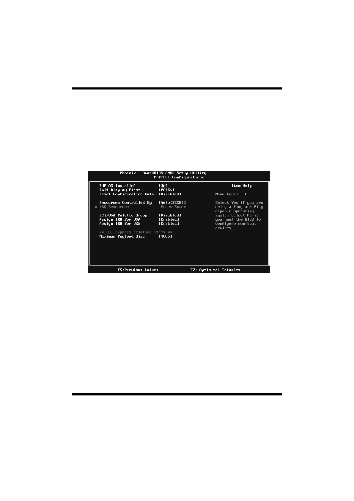
Figure 7: PnP/PCI Config urations
PNP OS Installed
When set to YES, BIOS will only initialize the PnP cards used for the boot
sequence (VGA, IDE, SCSI). The rest of the cards will be initialized by the PnP
operating system like Window™ 95. W hen set to NO, BIOS will initialize all
the PnP cards. For non-PnP operating systems (DOS, Netware™), this option
must set to NO.
The Choices: No (d efault), Yes.
Init Display First
This item allows you to decide to active whether PCI Slot or on-chip VGA first.
The Choices: PCIEx(default), P CI Slot, Onboard, AGP.
31
Page 33

P4M900-M7 FE/P4M890-M7 FE
Reset Configuration Data
The s ys tem BIOS supports the PnP featur e which requires the s ystem to record
whic h reso urces are ass igned and pro tects reso urces fro m co nflict.
Every peripheral devic e has a node, which is c alled ESCD. This nod e reco rds
whic h resourc es ar e ass igned to it. The syste m ne eds to record and upda te ESCD
to the memory locations. These loc ations ar e reserved in the system BIOS. If the
Disabled (default) option is chosen, the system‘s ESCD will update only when
the new configur ation var ies fro m t he last o ne. If the Enab led optio n is chos en,
the system is forced to update ESCDs and then is automatically set to the
“Disabled ” mode.
The above sett ings will be shown on the sc reen only if “Manual” is chos en for
the res ourc es c ontro lled by function.
Legac y is the t erm, which signifies that a resourc e is assigned to the ISA Bus
and p rovides non-P nP ISA add-o n cards. PC I / IS A PnP s ignif y that a r eso urce
is assigned to the PCI Bus or provides for ISA PnP add-on cards and
peripherals.
The Choices: Disabled (default), Enabled.
Resources Controlled By
By Choos ing “Auto(ESCD)” (default), the system BIOS will detect the system
resources and automatically assign the relative IRQ and DMA channel for each
peripheral. By Choosing “Manual”, the user will need to assign IRQ & DMA for
add-on cards. Be sure that there are no IRQ/DMA and I/O port conflicts.
The Choices: Auto (ESCD) (default), Manual.
IRQ Resources
This submenu will allo w you to assign each system interrupt a type, depend ing
on the type of device using the interrupt. When you press the “Press Enter” tag,
you will be directed to a submenu that will allow you to configure the sys tem
interrupts. This is only configurable when “Resources Controlled By” is set to
“Manual”.
IRQ-3 assigned to PCI Device
IRQ-4 assigned to PCI Device
IRQ-5 assigned to PCI Device
IRQ-7 assigned to PCI Device
IRQ-9 assigned to PCI Device
IRQ-10 assigned to PCI Device
IRQ-11 assigned to PCI Device
IRQ-12 assigned to PCI Device
IRQ-14 assigned to PCI Device
IRQ-15 assigned to PCI Device
32
Page 34

P4M900-M7 FE/P4M890-M7 FE
PCI / VGA Palett e Snoop
Some old graphic controllers need to “snoop” on the VGA palette and then map
it to their disp lay as a way to provide boot information and VGA compatibility.
This item allows such snooping to take place.
The Choices: Disabled (default), Enabled
Assign IRQ For VGA
This item allows the users to choose which IRQ to assign for the VGA.
The Choices: Enabled (default), Disabled.
Assign IRQ For USB
This item allows the users to choose which IRQ to assign for the USB.
The Choices: Enabled (default), Disabled.
Ma xi mu m Payload Size
Set t he maximum payload s ize fo r Transaction packets (TLP ).
The Choice: 4096 (default.), 128, 256, 512, 1024, 2048.
33
Page 35

P4M900-M7 FE/P4M890-M7 FE
8 PC Health Status
Figure 8: PC Health Status
Smart Fan Option
34
Page 36

P4M900-M7 FE/P4M890-M7 FE
CPU Smart Fan
T his ite m a llows yo u to c ontrol the C PU Fan.
The Choices: Disabled (default), Auto.
Smart Fan Calibration
Choose this item and then the BIOS will auto test and detect the CPU fan
functions and show CPU fan speed.
PWM Duty Off<℃ >
If the CPU Temperature is lower than the set value, FAN will turn off.
The Choices: Min=0,.Max=127, Key in a DEC number.
PWM Duty Start<℃>
CPU fan s tarts to wo rk under smart fan func tion when arrive this set
value.
The Choices: Min=0,.Max=127, Key in a DEC number.
Start PWM Value
Whe n CPU temperature arrive s to the se t value, the CPU fan will wo rk
under Smart Fan F unction mod e. T he range is from 0~127, wit h an
interval of 1.
The Choices: Min=0,.Max=127, Key in a DEC number.
Smart Fan Slope
Increasing the value of s lope PWM will raise the sp eed of CPU fan.
The Choices: Min=1,.Max=127, Key in a DEC number.
Shutdown Temperature
This item allows you to set up the CPU shutdo wn Temperature. This item is
only effective under Windows 98 ACPI mode.
The Choices: 60℃/ 140℉, 65℃/ 149℉, 70℃/ 158℉ , 75℃/ 167℉, 8 0℃/ 176
℉, 85℃/ 185℉(default), 90℃/ 167℉, Disabled.
CPU Vcore, NB Vcore, +3.3V, +5.0V, +12V, DRAM Voltage,
VTT Voltage, Voltage Battery
Detect the sys t em’s voltag e status a utomat ically.
Current CPU Temp
This field dis p lays the c urr ent temp er ature of CPU.
Current CPU FAN Speed
This field dis p lays the c urr ent speed of CPU fan.
35
Page 37

P4M900-M7 FE/P4M890-M7 FE
Current SYS FAN Speed
This field dis p lays t he c urrent speed SYSTEM fan.
Show H/W Monitor in POST
If you co mp uter contains a monito ring syste m, it will show PC health st at us
during POST stage. The item offers several different delay times.
The Choices: Enabled (default), Disabled.
36
Page 38

P4M900-M7 FE/P4M890-M7 FE
9 Performance Booster Zone
Figure 9: Performance Booster Zone
DRAM Clock/Drive Control
This item controls the DRAM Clock. Highlight “Press Enter” next to the
“DRAM Clock/Drive Control” label and pressing the enter key will take you a
submenu with the following options:
Figure 9.1: DRAM Clock/Drive Control
37
Page 39

P4M900-M7 FE/P4M890-M7 FE
DRAM Clock
T his ite m d eter mines DR AM c lock.
The Choices: By SPD (default), 100MHz, 133MHz, 166MHz, 200MHz,
266MHz, 333MHz .
DRAM Timing
T his ite m d eter mines DR AM c lock/ timing.
The Choices: Auto by SPD (default), Manual, Turbo, Ultra.
SD RAM CAS Latency
When DRAM is installed, the number of clock cycles of CAS latency depends
on the DRAM timin g.
The Choices: 2.5 /4( defa ult).
Bank Interleave
This item allows you to enable or disable the bank interleave feature.
The Choices: Disabled (default).
Precharge to Active (tRP)
This item allows you to specify the delay from precharge command to activate
command.
The Choices: 4T (default).
Active to Precharge (tRAS)
T his ite m a llows yo u to s pecif y the min imum r ow activ e time (tRAS).
The Choices: 07T (default).
Active to CMD (tRCD)
Use this item to specify the delay from the activation of a bank to the time that
a read or write command is accepted.
The Choices: 4T (default).
REF to ACT/REF to REF (Trfc)
This item allows you to determine the selection for REF to ACT /REF to REF
(tRFC).
The Choices: 20T/21T (default).
38
Page 40

P4M900-M7 FE/P4M890-M7 FE
ACT (0) to ACT (1) (tRRD)
T his ite m a llows yo u to d eter mine th e sele ction fo r ACT (0 ) to ACT (1) (tRRD)
The Choices: 3T (default).
1T CMD S uppor t
The Choices: Disable (default), Auto.
DDR2 On Die Termination
This option allows you to choose the working type of ODT .
The Choices: ODT Always ON (default), Dynamic ODT, ODT Always OFF.
CPU CLOCK
This it em allows you to select CPU Clock, and CPU over c loc king.
Special Notice:
If the syst em’s freq uency that you are selected is not func tioning, t here are two
methods of booting-up the system.
Method 1:
Clear the C OMS d ata b y setting the JCO MS1 ((2-3) closed ) ) as “ON” s tatus. All
the CMOS data will be loaded as defaults setting.
Method 2:
Press the <I nsert> key and Po wer button simult aneo usly, after that keep -on
press ing the <Insert> key until the power-on screen showed.
This action will boot-up the system according to FSB of the processor
It’s strongly reco mmended to set CPU Vcore and clock in default setting. If the
CPU Vcore and clock are not in default s etting, it may cause CPU or M/B
damage.
The Choices: 100MHz(default); Min=1 00, Max= 400, key in a DEC number.
Async PCIE CLOCK
This item allows you to select Async PCIE clock.
Min= 100 Max= 150 Key in a DEC nu mber.
The Choices: 100MHz(default) ; Min=10 0, Max=150, key in a DEC number.
CPU Clock Ratio
This item allows you to select the CPU Ratio.
Min= 6 Max= 50 Key in a DEC number.
The Choices: 6X (default).
39
Page 41

P4M900-M7 FE/P4M890-M7 FE
Spread Spectrum
This item allows you to enable/disable the Spread Spec trum function.
The Choices:+/- 0.25% (default ), +/- 0. 5%, Disabled, -0.5%, -1.0%.
DDR Voltage
This item allows you to select DDR Voltage.
The Choices: StartUp (default), +0.10V, +0.20V, +0.30V, +0.40V, +0.50V,
+0.60V, +0.70V.
40
 Loading...