

Page 1

P4M900-M7 FE/P4M890-M7 FE Setup Manual
FCC Inf or m at ion and Copyri ght
This equipment has been tested and found to comply with the limits of a Class
B digital device, pursuant to Part 15 of the FCC Rules. T hese limits are designed
to provide reasonable protec tion against harmful i nterference in a residential
installation. This equipment generates, uses , and can radiate radio frequency
energy and, if not installed and used in accordance with the instructions, may
cause harmful interference to radio communications. There is no guarantee
that interfe rence wil l no t occur in a particu la r ins ta llatio n.
The vendor makes no representa tions o r warranties with respec t to th e
contents here and specially disclaims any implied warranties of merchantability
o r f i tn es s fo r a ny p u rp os e . F urt he r t he ve nd o r res e rves the ri g ht to r ev is e t his
publication and to make changes to the contents here without obligation to
notify any party beforehand.
D uplic a tion of t his publication, i n pa rt o r i n whole, is not al lo wed wi t hout fi rst
obtaining the vendor’s approval in writing.
The content of this user’s manual is subject to be changed without notice and
we will not be res ponsible for any mis takes found in this user’s manual. All the
brand and produc t names are trademarks of their respective companies .
Page 2

Table of Contents
Chapter 1 : In tr o ducti on.....................................................3
1.1 Before You Start...................................................................3
1.2 Package Checklist................................................................ 3
1.3 Motherboard Features.......................................................... 4
1.4 Rear Panel Connectors.......................................................... 5
1.5 Mo t he r bo ar d Layou t............................................................6
Chapter 2 : Hard ware In s tall ation........................................7
2.1 Installing Central Processing Unit (CPU)................................ 7
2.2 Fan He ade rs.........................................................................9
2.3 Installing System Me mo ry.....................................................10
2.4 Con necto rs a nd Slo ts............................................................12
Chapter 3 : Header s & Ju mp ers S etu p.................................14
3.1 How to Se t u p Jum per s..........................................................14
3.2 Det ail Settin gs.....................................................................14
Chapter 4 : R AID Fu ncti ons...............................................20
4.1 Operation Syste m................................................................20
4.2 Raid Arrays.........................................................................20
4.3 How RA I D Work s.................................................................20
Chapter 5 : Useful Hel p.....................................................22
5.1 Driver Instal latio n No te.......................................................22
5.2 Award B IOS Bee p Code........................................................23
5.3 Extra Informati on ................................................................23
5.4 Troubleshooting...................................................................24
Appenden cies: S PEC In Other Langua ge.............................2 6
Germa n................................................................................................26
France..................................................................................................28
Italian..................................................................................................30
Spanish................................................................................................32
Portuguese ...........................................................................................34
Polish...................................................................................................36
Russian ................................................................................................38
Arabic..................................................................................................40
Japanese..............................................................................................42
Page 3

P4M900-M7 FE/P4M890-M7 FE
CHAPTER 1: INTRODUCTION
1.1 BEFORE YOU START
Tha nk you for choosing our p roduct. Be fore you start ins talling the
mothe rboa rd, plea se make su re you fo llo w the ins tru ctio ns belo w:
Prepare a dry and stable wo rking environment with
s uf ficie nt li gh ting.
Always disconnect the computer from power outlet
be fo re ope ration .
Befo re you take the mo the rboa rd ou t f rom a n ti -s ta ti c
bag, ground yourself properly by touching any safely
grounde d appliance, o r use grounded wrist strap to
remove the static charge.
Avo id tou ch ing the compone nts o n m o the rboa rd o r the
rea r side of the boa rd unless necessary. Ho ld the boa rd
on the edge , do no t try to be nd o r flex the board.
Do no t leave an y un fastened sma ll pa rts inside the
case afte r installation. Loose parts will cause short
circuits which ma y damage the equipment.
Keep the computer from dangerous area, such as heat
sou rce , humid a ir and water.
1.2 PACKAGE CHECKLIST
HDD Cable X 1
I ns talla tion Gu ide X 1
Fu lly Se tup Drive r CD X 1 ( fu ll ve rsion m anua l f iles ins ide )
Rear I/O Panel for ATX Case X 1
FDD Cable X 1 (optional)
Se ria l ATA Cab le X 1 ( op tiona l)
USB 2.0 Cable X1 (optional)
Se ria l ATA P o we r Cab le X 1 (o ptio nal)
Not e: The package contents may differ by area or your motherboard version.
3
Page 4
Motherboard Manual
p
/
p
/
1.3 MOTHERBOARD FEATURES
P4M900-M7 FE P4M890-M7 FE
LGA 77 5
Intel Core2Duo/ Pentium 4 / Pentium D /
Celeron D / Celeron 4xx processor up to 3.8
GHz
CPU
FS B 533 / 800 / 1066 MHz 533 / 800 / 1066 MHz
Chipset
Graphic
Super I/O
Main
Memory
IDE
SATA
LAN PHY
Sound
Codec
*It is recommended to use
95W power co ns um pt ion.
Supports Hyper Thre ading
Bit / Enhanced Intel S peedStep®/ Intel
Extended Memor y 64 technology
VIA P4M900
VIA VT8237A
Chr ome9 HC 3D / 2D Gr ap hi c s
Max Shared Vide o Memory is 256 MB
ITE 871 2F
Provides the most commonly used legacy
Super I/O functionality.
Low Pin C ount Int erfac e
Environment Control initiatives,
H/W Monitor
Fan S pee d Co nt roller
ITE' s "S mart G uardia n" func tion
DIMM Slots x 2
Supports D DR2 5 33 / 667
Eac h DIMM s up ports 2 56/ 512MB/1GB/ 2GB
DDR2
Max Memory Capicity 4GB
Single Channel Mode DDR2 memory
module
Registered DIMM and ECC DIMM is not
supported
Integrated IDE Controller
Ultra DMA 33~133 B us Master Mode
supports PIO Mo de 0~4,
Integrated Seri al ATA Controller
Data transfer rates up to 1.5 Gb/s.
SATA Version 1.0 specification complia nt.
Realtek RTL 8201CL PH Y
10 / 100 Mb/s auto negotiation
Half / Full duplex capability
AL C662
5.1 cha nnel s a udio o ut
High- Defi nit ion Au dio s upport
rocessors with
Execute Dis able
4
LGA 77 5
Intel Core2Duo/ Pentium 4 / Pentium D /
Celeron D / Celeron 4xx processor up to 3.8
GHz
*It is recommended to use
95W power co ns um pt ion.
Supports Hyper Thre ading
Bit / Enhanced Intel S peedStep®/ Intel
Extended Memor y 64 technology
VIA P4M890
VIA VT8237A
Chr ome9 HC 3D / 2D Gr ap hi c s
Max Shared Vide o Memory is 256 MB
ITE 871 2F
Provides the most commonly used legacy
Super I/O functionality.
Low Pin C ount Int erfac e
Environment Control initiatives,
H/W Monitor
Fan S pee d Co nt roller
ITE' s "S mart G uardia n" func tion
DIMM Slots x 2
Supports D DR2 5 33 / 667
Eac h DIMM s up ports 2 56/ 512MB/1GB/ 2GB
DDR2
Max Memory Capicity 4GB
Single Channel Mode DDR2 memory
module
Registered DIMM and ECC DIMM is not
supported
Integrated IDE Controller
Ultra DMA 33~133 B us Master Mode
supports PIO Mo de 0~4,
Integrated Seri al ATA Controller
Data transfer rates up to 1.5 Gb/s.
SATA Version 1.0 specification complia nt.
Realtek RTL 8201CL PH Y
10 / 100 Mb/s auto negotiation
Half / Full duplex capability
AL C662
5.1 cha nnel s a udio o ut
High- Defi nit ion Au dio s upport
rocessors with
Execute Dis able
Page 5
P4M900-M7 FE/P4M890-M7 FE
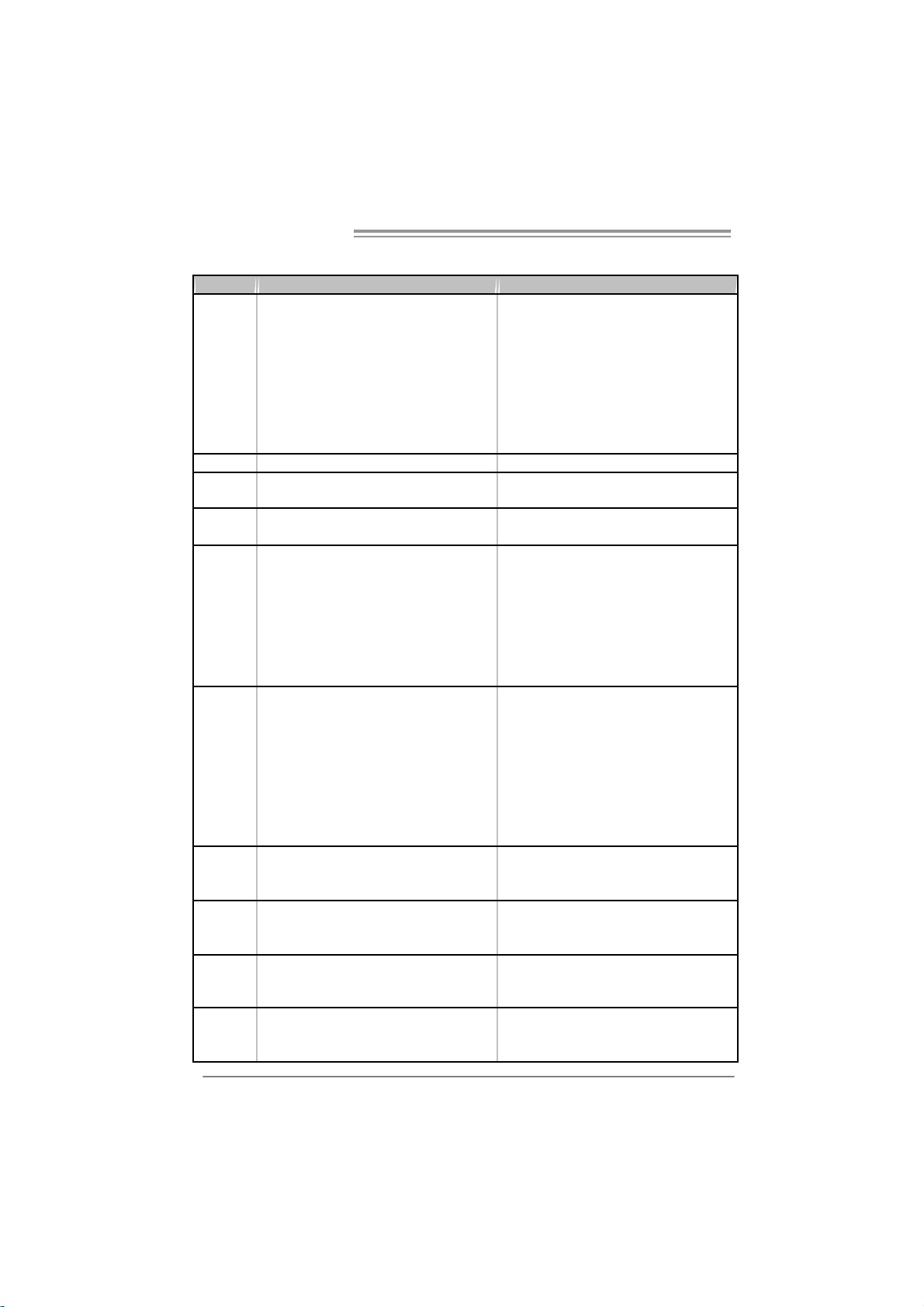
P4M900-M7 FE P4M890-M7 FE
PCI Express x 16 slot x1 PCI Express x 16 slot x1
PCI Express x 1 slot x1 PCI Express x 1 slot x1 Slots
PCI s lot x2 PCI s lot x2
Floppy connector x1 Floppy connector x1
Printer Port C onnector x1 Printer Port C onnector x1
IDE C o nnect or x2 IDE Co nnect or x2
SATA Connector x2 SATA Connector x2
Front Pa nel Co nnec t or x1 Front Pa nel Co nnec tor x1
On Board
Connector
Back Panel
I/O
Board Si z e 190 mm (W) x 24 4 mm (L) 190 mm (W) x 244 m m (L )
Special
Feature
OS
Suppor t
Front Audi o Connector x1 Front Audi o Connector x1
CD-in C o nnect or x1 CD-in Co nnect or x1
CPU Fan hea der x1 CPU Fan hea der x1
System Fan hea der x1 Sys tem Fan hea der x1
Clear CMOS header x1 Clear CMOS header x1
USB connector x2 USB connector x2
Power Connector (24pi n) x1 Power Connector (24pi n) x1
Power Connector (4pin) x1 Power Connector (4pin) x1
PS/2 Keyb oard x1
PS/2 Mo use x1
Serial Port x1
VGA Port x1
LAN port x1
USB Port x4
Audio Jack x3
RAID 0 / 1 support RAID 0 / 1 support
Windows 2000 / XP / VISTA
Biostar Reserves the right t o add or remo ve
support for any OS with or without notice.
PS/2 Keyb oard x1
PS/2 Mo use x1
Serial Port x1
VGA Port x1
LAN port x1
USB Port x4
Audio Jack x3
Windows 2000 / XP
Biostar Reserves the right t o add or remove
support for any OS with or without notice.
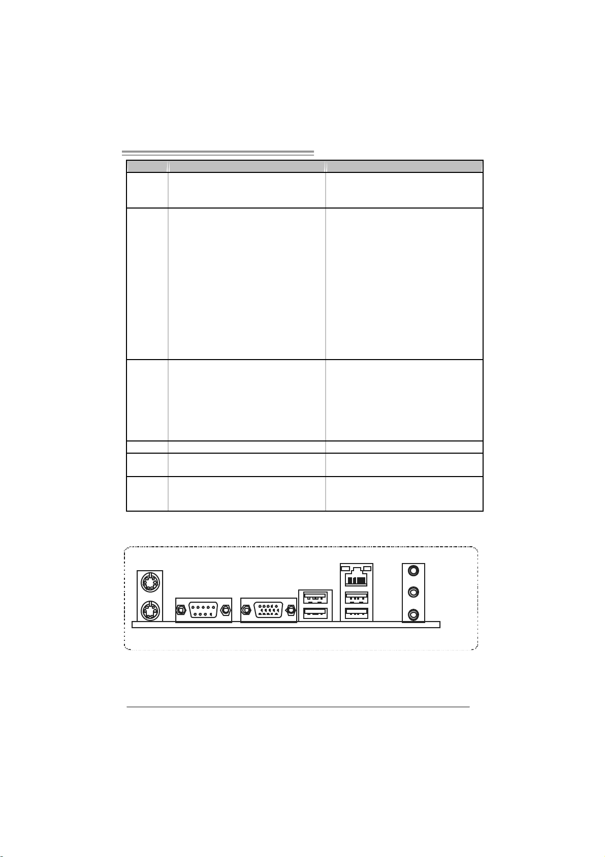
1.4 REAR PANEL CONNECTORS
PS/2
Mouse
PS/2
COM1 VGA
Keyboard
Since t he au dio c hip s upports H i g h D efi niti on A udio Speci fi c atio n, t he func tion of eac h a udi o
jack c an be defi ne d b y sof tw ar e. T he in put / out put fu nction o f e ach au dio jac k l i sted ab o ve
represe nts t he def ault s etti ng . H o we ver, when c on necti ng exter nal micr oph on e to t he au dio
port, pleas e us e t he Lin e I n (blu e) an d M ic In (Pi n k) a udio j ac k.
LA N
Li ne I n /
Surround
Line O ut
Mic In 1/
Bass/ Center
USBX2USBX2
5
Page 6
Motherboard Manual
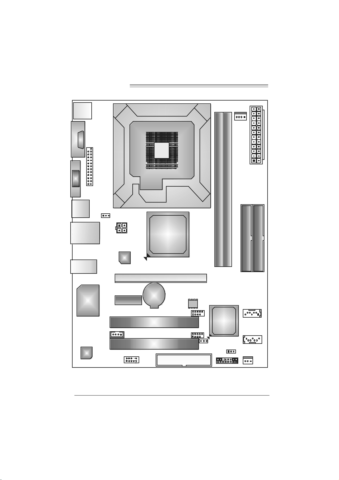
1.5 MOTHERBOARD LAYOUT
JKBMS1
C
O
J
M
C
1
O
M
1
JVGA1
JPRNT1
JU SB1
JUSBLAN1
JAUDIO1
JUSBV1
JATXPWR2
LAN
LGA775
CPU 1
P4M900
or
P4M890
DIMM1
DIMM2
JCFAN1
JATXPWR1
IDE1
IDE2
6
Super
I/O
JCDIN1
Codec
Note: represents the 1■
JA UDIO F1
PCI -EX1 _1
PCI -E X16
BAT1
PCI1
PCI2
st
pin.
JU SB 2
JUSB3
FDD 1
BI OS
JUSBV2
VIA
VT8237A
JCMOS1
J P AN EL 1
JSATA2
JSATA1
JSFAN1
Page 7
P4M900-M7 FE/P4M890-M7 FE
CHAPTER 2: HARDWARE INST ALL ATION
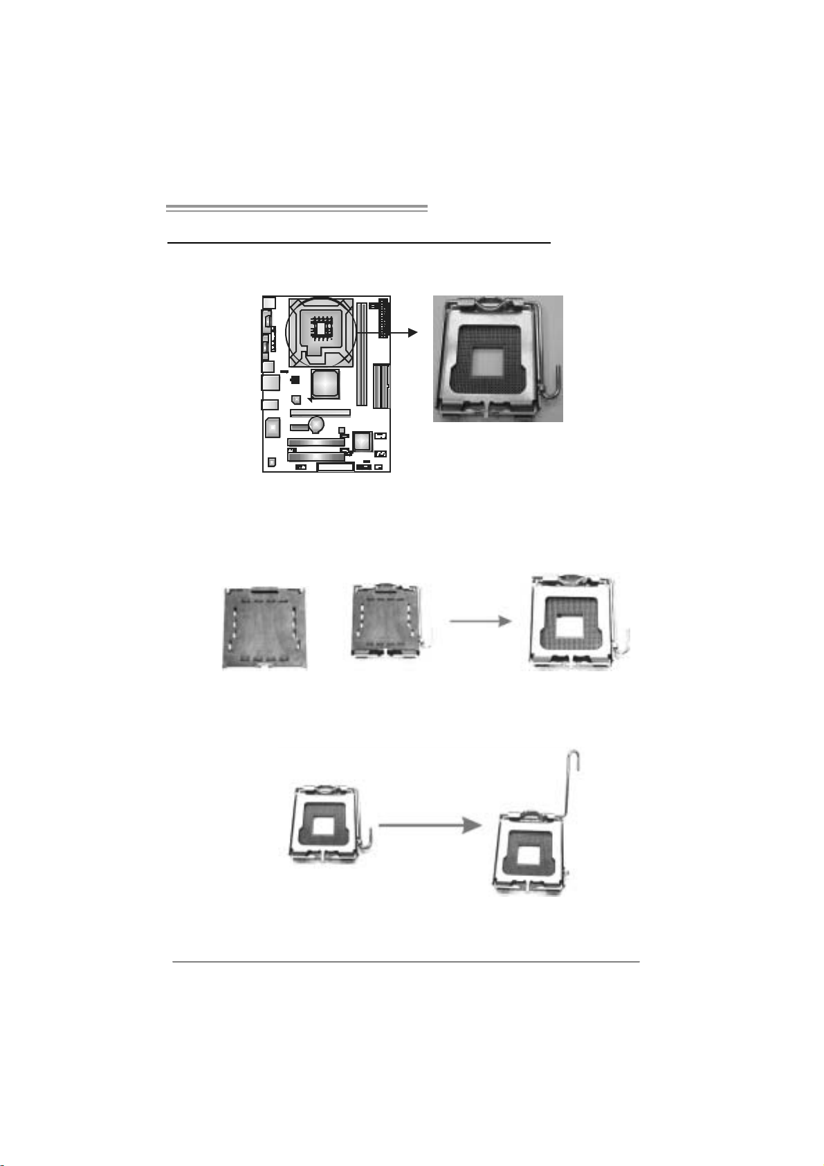
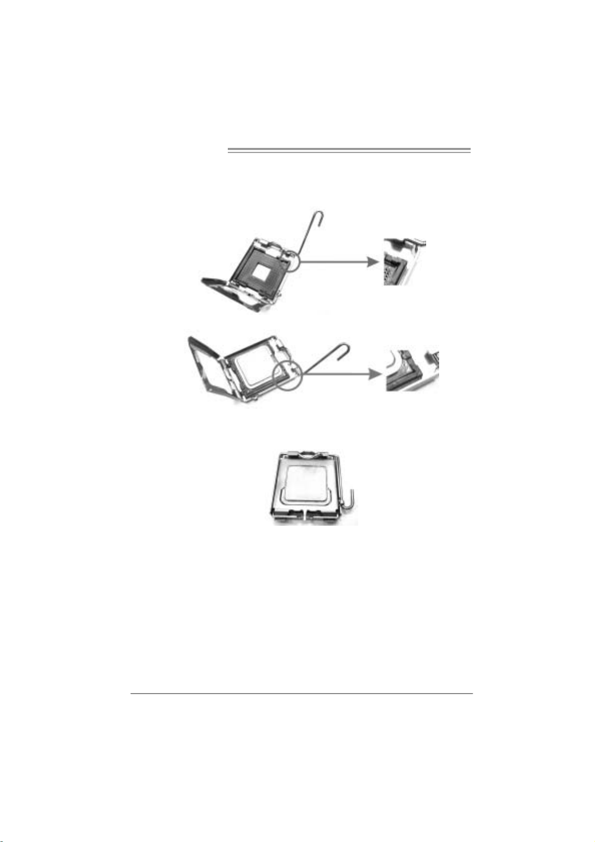
2.1 INSTALLING CENTRAL PROCESSING UNIT (CPU)
Special Notice:
Remo v e Pin Cap before installa tion, and m ake goo d preservatio n
for future use. When the CPU is remov ed, cov er the Pin Cap on the
empty so cket to ensure pin legs won’ t be da mag e d.
Pin Cap
Step 1: Pull the socket locking lever out from the socket and then raise
the lever up to a 90-degree angle.
7
Page 8
Motherboard Manual
Step 2: Look for the triangular cut edge on socket, and the golden dot on
CPU should point forwards this triangular cut edge. The CPU will
fit only in the correct orientation.
Step 2-1:
Step 2-2:
Step 3: Hold the CPU down firmly, and then lower the lever to locked
positi on to complete the installation.
Step 4: Put the CPU Fan and heatsink assembly on the CPU and buckle it
on the retention frame. Connect the CPU FAN power cable into
the JCFAN1. This completes the installation.
8
Page 9
P4M900-M7 FE/P4M890-M7 FE
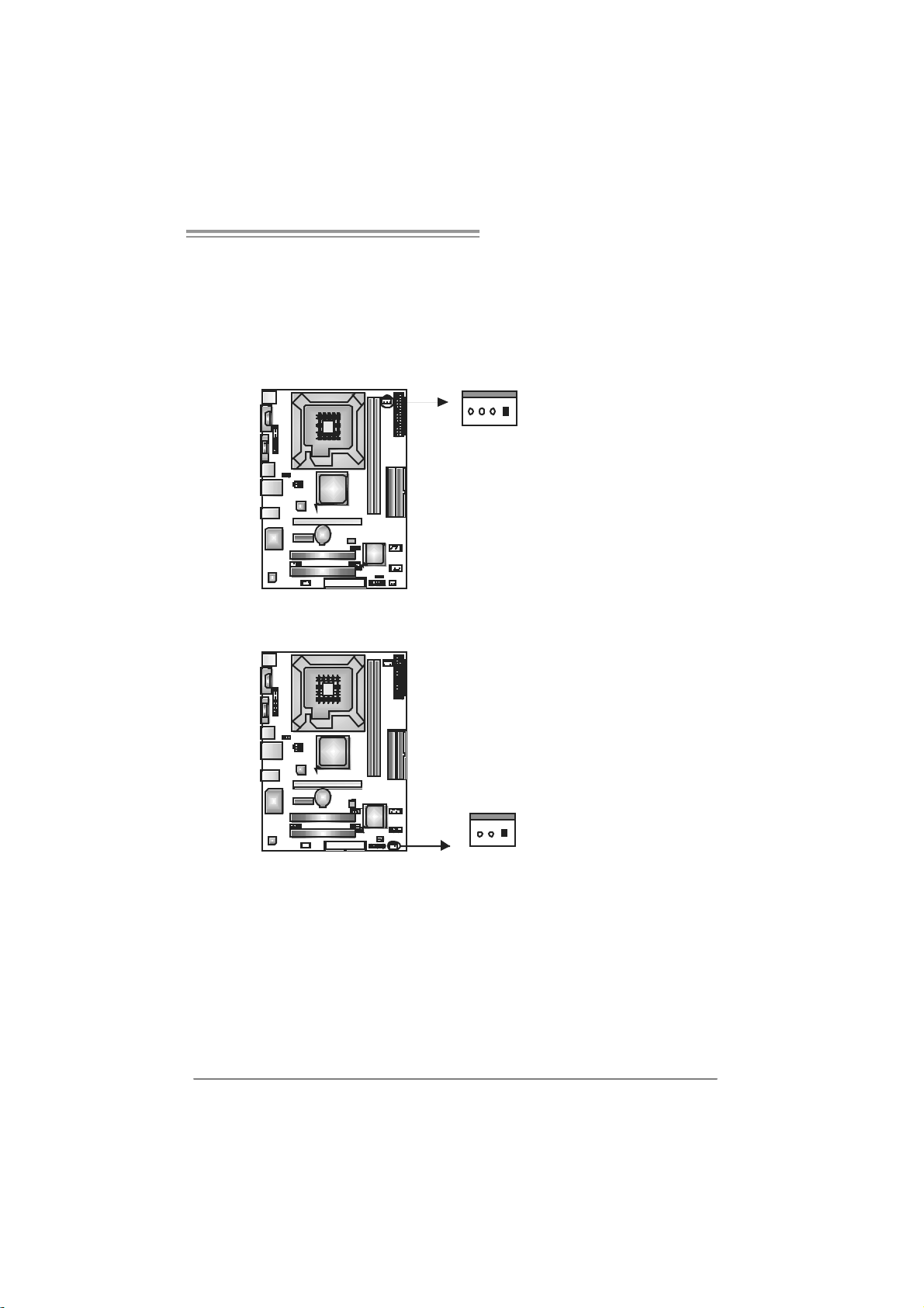
2.2 FAN HEADERS
These fan headers support cooling-fans built in the computer. The fan
cable and connector may be different according to the fan manufacturer.
Connect the fan cable to the connector while matching the black wire to
pin#1.
JCFAN1: CPU Fan Header
Pin
14
JSFAN 1: System Fan H ead er
Assignment
1 Ground
2 +12V
3 FAN RPM rate
sense
4 Smart Fan
Control
Pin
Assignment
1 Ground
2 +12V
3 FAN RPM rate
sense
13
Note:
The J SFAN1 suppor ts 3- pi n he ad con nect or a nd the JC FAN1 s u ppor ts 4-pi n he ad
conn ector . When c onnecti ng with wires onto c onnec t ors, pl ease n ote that t he r ed wir e i s
the positi ve a nd s ho ul d be connect ed to pin# 2, an d th e bl ack wi r e i s Groun d a nd s hould
be c onnect ed to GND.
9
Page 10
Motherboard Manual
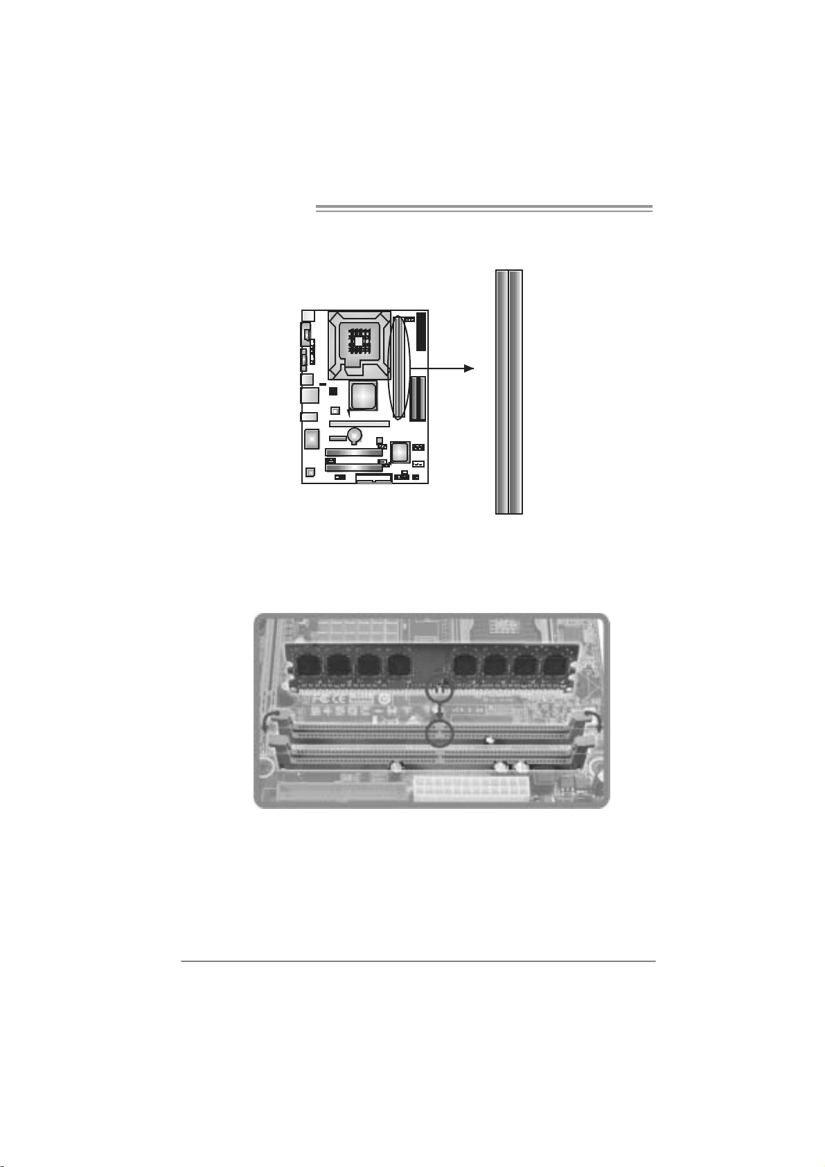
2.3 INSTALLING SYSTEM MEMORY
A. Me mo ry Modu le s
DIM M1
DIM M2
1. Unlock a DIMM slot by pressing the retaining clips outward. Align a
DIMM on the slot such that the notch on the DIMM matches the
break on the Slot.
10
Page 11
P4M900-M7 FE/P4M890-M7 FE
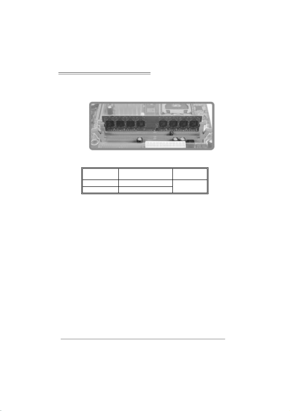
2. Insert the DIMM vertically and firmly into the slot until the retaining
chip snap back in place and the DIMM is properly seated.
B. Memory Capacity
DI MM Socket
Location
DIMM1 256MB/512MB/1GB/2GB
DIMM2 256MB/512MB/1GB/2GB
DDR2 Module
To t a l Memo r y
Size
Max i s 4GB.
11
Page 12
Motherboard Manual
2.4 CONNECTORS AND SLOTS
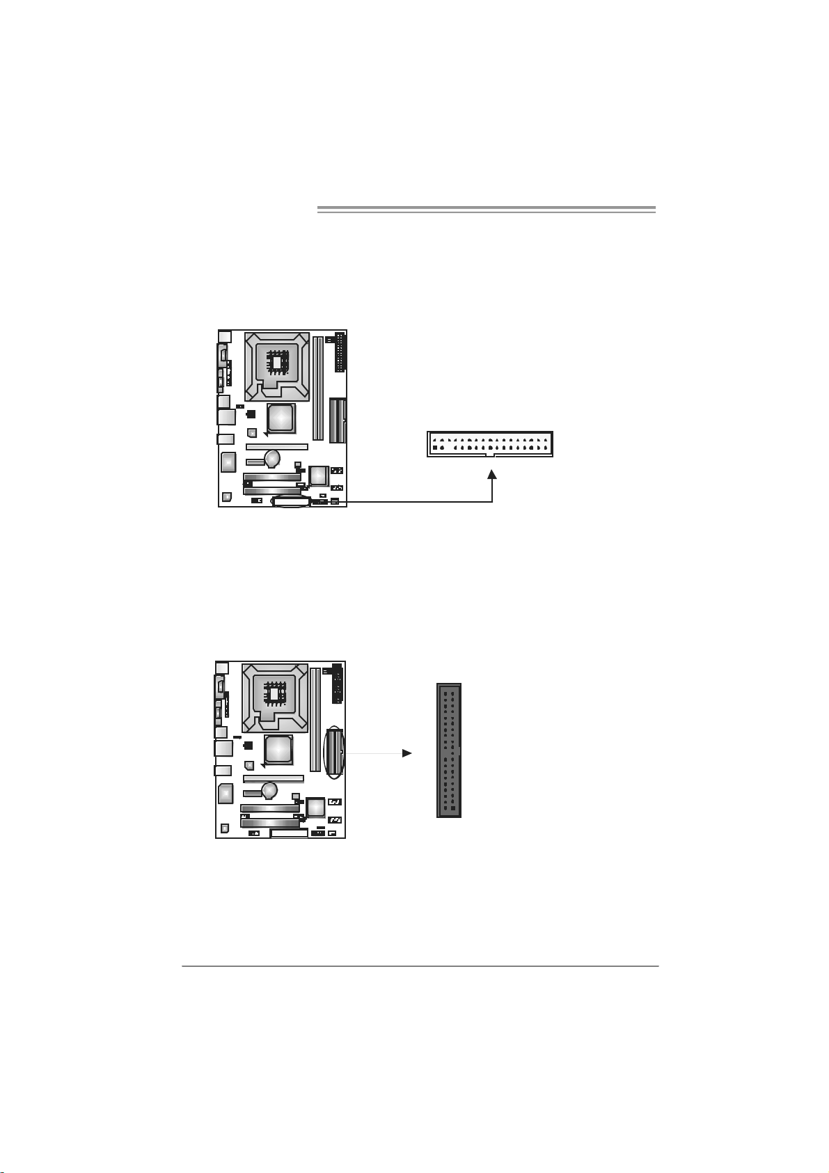
FDD1: Flo ppy Disk Conne c to r
The motherboard prov ides a standard floppy disk connector that supports 360K,
720K, 1.2M, 1.44M and 2.88M floppy disk ty pes. This connector supports the
prov ided f loppy drive ribbon cable.
IDE1/IDE2: H ard Disk Connectors
The motherboard has a 32-bit Enhanced PCI IDE Controller that prov ides PIO
Mode 0~4, Bus Mas ter, and Ultra DMA 33/66/ 100/133 f unctionality. It has t wo
HDD connectors: ID E1 (prim ary ) and IDE2 (secondary ).
The IDE connectors can connect a master and a slave drive, so you can
connect up to four hard disk drives. The f irst hard drive should always be
connected to IDE1.
2
1
3940
21
34
33
12
IDE2IDE1
Page 13
P4M900-M7 FE/P4M890-M7 FE
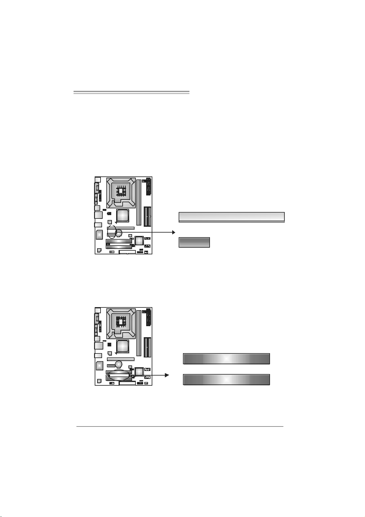
PCI-EX16: P CI -Expr es s x1 6 S lot
- PCI-Express 1.0a compliant.
- Maximum theoretical realized bandwidth of 4GB/s simultaneously per
direction, f or an aggregate of 8GB/s totally.
PCI-EX1_1: PCI-Express x1 Slot
- PCI-Express 1.0a compliant.
- Data transf er bandwidth up to 250MB/s per direction; 500MB/s in total.
- PCI-Express supports a raw bit-rate of 2.5Gb/s on the data pins.
- 2X bandwidth ov er the traditional PCI architecture.
PCI-EX16
PCI-EX1_1
PCI1/PCI2: Peripheral Component Interconnect Slots
This motherboard is equipped with 2 standard PCI slots. PCI stands f or
Peripheral Component Interconnect, and it is a bus standard for expansion
cards. This PCI slot is designated as 32 bits.
PCI1
PCI2
13
Page 14

Motherboard Manual
CHAPTER 3: HEADERS & JUMPERS SETUP
3.1 HOW TO SETUP JUMPERS
The illustration shows how to set up jumpers. When the jumper cap is
placed on pins, the jumper is “close”, if not, that means the jumper is
“open”.
Pin opened Pin closed Pin1-2 closed
3.2 DETAIL SETT INGS
JPANEL1: Front Panel Header
This 16-pin connector includes Power-on, Reset, HDD LED, Power LED, and
speaker connection. It allows us er t o c onnec t the PC case’s f ront panel switc h
functions.
14
PWR_LED
On/ Off
-
9
18
++
+
SPK
16
-
RST
HL E D
Pin Assignment Function Pin Assignment Functio n
1 +5V 9 N/A
2 N/A 10 N/A
3 N/A 11 N/A N/A
4 Speaker
5 HDD LED (+) 13 Power LED (+)
6 HDD LED (-)
7 Ground 15 Power button
8 Reset control
Speaker
Connector
Hard drive
LED
Reset button
12 Power L E D (+)
14 Power L E D (-)
16 Ground
N/A
Power LED
Power-on button
Page 15

P4M900-M7 FE/P4M890-M7 FE
ATX Power Source Co nnect or: JAT X PWR1
JATXPWR1 allows user to connect 24-pin power connector on the ATX power
supply.
12
1
Pin Assignment Pin Assignment
13 +3.3V 1 +3.3V
14 -12V 2 +3.3V
15 Ground 3 Ground
16 PS_ON 4 +5V
17 Ground 5 Ground
18 Ground 6 +5V
19 Ground 7 Ground
20 NC 8 PW _OK
21 +5V 9 Standby Voltage+5V
22 +5V 10 +12V
23 +5V 11 +12V
24 Ground 12 +3.3V
24
13
JATXPW R2: AT X Powe r Sou rce Con ne ctor
By connecting this connector, it will provide +12V to CPU power circuit.
Pin
1
23
4
Assignment
1 +12V
2 +12V
3 Ground
4 Ground
Note:
Befor e p ower on t he syst em, pleas e make sur e th at b oth J ATXP WR1 and JAT XPWR2
conn ector s ha ve bee n pl ug g ed- i n.
15
Page 16

Motherboard Manual
JUSB2/JUSB3: Headers for USB 2.0 Ports at Fron t Panel
This header allows user to connect additional USB cable on the PC f ront panel,
and also can be connected with internal USB devices, like USB card reader.
210
19
JSATA1 /JS ATA2: Se rial ATA Conne ctors
The motherboard has a PCI to SATA Controller with 2 c hannels SATA interf ac e,
it satisfies the SATA 1.0 spec and with transfer rate of 1.5Gb/s.
JSATA2
147
14 7
JUSB2
JUSB3
Assignment
Pin
1 +5V (fused)
2 +5V (fused)
3 USB4 USB5 USB+
6 USB+
7 Ground
8 Ground
9 Key
10 NC
Pin
Assignment
1 Ground
2 TX +
3 TX 4 Ground
5 RX6 RX+
7 Ground
JAUDIOF1: Front Panel Audio Header
This header allows user to connect the front audio output cable with the PC f ront
panel. This header allows only HD audio front panel connector; AC’97 connector
is not acceptable.
16
J SATA 1
210
19
Pin Assignment
1 Mic Left in
2 Ground
3 Mic Right in
4 GPIO
5 Right line in
6 Jack Sense
7 Front Sens e
8 Key
9 Left line in
10 Jack Sens e
Page 17

P4M900-M7 FE/P4M890-M7 FE
JCDIN1: CD-R OM A ud io- in Connector
This connector allows user to connect the audio source f rom the variaty devices,
like CD-ROM, DVD-ROM, PCI sound card, PCI TV turner card etc.
Assignment
Pin
1 Left Channel Input
2 Ground
3 Ground
4 Right Channel Input
14
JCMOS 1 : C l ea r CMO S Hea der
By placing the jumper on pin2-3, it allows user to restore the BIOS saf e setting
and the CMOS data, please carefully f ollow the procedures to avoid damaging
the motherboard.
13
Pin 1-2 Close:
Normal Operation (default).
1
13
Pin 2-3 Close:
Clear CMOS data.
※ Clear CMOS Procedures:
1. Remov e AC power line.
2. Set the jumper to “Pin 2-3 close”.
3. Wait for f ive seconds.
4. Set the jumper to “Pin 1-2 close”.
5. Power on the AC.
6. Reset y our desired pas sword or clear the CMOS data.
3
17
Page 18

Motherboard Manual
JPRNT1: Printer Port Connector
This header allows you to connector printer on the PC.
Pin Assignment Pin Assignment
1 -Strobe 14 Ground
2 -ALF 15 Data 6
3 Data 0 16 Ground
4 -Error 17 Data 7
5 Data 1 18 Ground
6 -Init 19 -ACK
7 Data 2 20 Ground
8 -Scltin 21 Busy
9 Data 3 22 Ground
10 Ground 23 PE
11 Data 4 24 Ground
12 Ground 25 SCLT
13 Data 5 26 Key
25
1
2
18
Page 19

P4M900-M7 FE/P4M890-M7 FE
JUS B V1/JUSBV2 : Powe r Sou rce Heade rs for USB Ports
Pin 1-2 Clo se:
JUSBV1: +5V for U SB port s at JUSB1/JUSBLAN1.
JUSBV2: +5V for U SB port s at f ront panel (JUSB2/JUSB3).
Pin 2-3 Clo se:
JUSBV1: +5V STB f or U SB ports at JUSB1/JUSBLAN1.
JUSBV2: +5V STB f or U SB ports at f ront panel (JUSB2/JUSB3).
JUSBV1
13
JU SBV 2
13
13
Pin 1-2 close
13
Pin 2-3 close
19
Page 20

Motherboard Manual
CHAPTER 4: RAID FUNCTIONS
4.1 OPERATION SYST EM
Supports Windows XP, Windows 2000 Professional, and Windows Vista.
4.2 RAID ARRAYS
RAID supports the following types of RAID arrays:
RAID 0: RAID 0 defines a disk striping scheme that improves disk read and write times for
many applications.
RAID 1: RAID 1 defines techniques for mirroring data.
4.3 HOW RAID WORKS
RAID 0:
The controller “ stripes” data across multiple d ri ves in a RAID 0 array system. It breaks
up a large file into smaller blocks and performs disk reads and writes across multiple
drives in parallel. The size of each block is determined by the stripe size parameter,
which you set during the creation of the RAID set based on the system environment. This
technique reduces overall disk access t ime and offers high b andwidth.
Fea tures and Be nefits
Drives: Minimum 2, and maximum is up to 6 or 8. D epending on the
platform.
Uses: Intended for non-critical data requiring high data throughput, or any
env ironment that does not require f ault t olerance.
Benefits: provides increased data throughput, especially f or large files. No
capacity loss penalty f or parity.
Drawbacks: Does not deliver any fault tolerance. If any drive in t he array
f ails, all data is lost.
Fa ult Tolerance: No.
20
Block 1
Block 3
Block 5
Block 2
Block 4
Block 6
Page 21

P4M900-M7 FE/P4M890-M7 FE
RAID 1:
Every read and write is actually carried out in parallel across 2 disk drives in a RAID 1
array system. The mirrored (back up) copy of the data can reside on t he same disk or o n a
second redundant drive in the array. RAID 1 provides a hot-standby copy of data if the
active volume or drive is co rrupted or becomes unavailable because o f a h ardware failure.
RAID techniques can be applied for high-availability solutions, or as a form of automatic
backup that eliminates tedious manual backups to more expensive and less reliable
me d i a .
Fea tures and Be nefits
Drives: Minimum 2, and maximum is 2.
Uses: RAID 1 is ideal f or small databases or any other application that
requires f ault tolerance and minimal c apac ity.
Benefits: Provides 100% data redundancy. Should one driv e f ail, the
controller switc hes to the other drive.
Drawbacks: Requires 2 drives for the storage space of one driv e.
Perf ormance is impaired during drive rebuilds.
Fa ult Tolerance: Yes.
Block 1
Block 2
Block 3
Block 1
Block 2
Block 3
21
Page 22

Motherboard Manual
CHAPTER 5: USEFUL HELP
5.1 DRIVER INSTALLATION NOTE
After you installed your operating system, please insert the Fully Setup
Driver CD into your optical drive and install the driver for better system
performance.
You will see the following window after you insert the CD
The setup guide will auto dete ct your motherboard and operating system.
Note:
If thi s win dow di dn’ t sho w up aft er you i ns ert the Dr iver CD , please use fi l e br ows er to
locate an d e xecu te th e file SETU P.E XE un der yo ur o pti cal drive.
A. Driver Insta llation
To install the driver, please click on the Driver icon. The setup guide will
list the compatible driver for your motherboard and operating system.
Click on each device driver to launch the installation program.
B. Software Installatio n
To install the software, please click on the Software icon. The setup guide
will list the software available for your system, click on each software title
to launch the installation program.
C. Manual
Aside from the paperback manual, we also provide manual in the Driver
CD. Click on the Manual icon to browse for available manual.
Note:
You will need Acrobat R eader to open the manual file. Please download the latest version
of Acrobat Re ader software from
http://www.adobe.com/products/acrobat/readstep2.html
22
Page 23

P4M900-M7 FE/P4M890-M7 FE
5.2 AWARD BIOS BEEP CODE
Beep Sound Meanin g
One long beep followed by two short
beeps
High-low siren sound CPU overheated
One Short beep when system boot-up No error found during POST
Long beeps every other second No DRAM detected or install
Video card not found or video card
memory bad
System will shut down automatically
5.3 E
XTRA INFORMATION
CPU Overheated
If the system shutdown automatically after power on system for
seconds, that means the CPU protection function has been activated.
When the CPU is over heated, the motherboard will shutdown
automatically to avoid a damage of the CPU, and the system may not
power on again.
In this case, please double check:
1. The CPU cooler surface is placed evenly with the CPU surface.
2. CPU fan is rotated normally.
3. CPU fan speed is fulfilling with the CPU speed.
After confirmed, please follow steps below to relief the CPU protection
function.
1. Remove the power cord from power supply for seconds.
2 . Wa i t f o r se c o nd s.
3. Plug in the power cord and boot up the system.
Or you can:
1. Clear the CMOS data.
(See “Close CMOS Header: JCMOS1” section)
2 . Wa i t f o r se c o nd s.
3. Powe r on the syste m ag ai n.
23
Page 24

Motherboard Manual
e
5.4 TROUBLESHOOTING
Probable Solution
1. No power to the system at all
Power light don’t illuminate, f an
inside power supply does not turn
on.
2. Indicator light on key board does
not turn on.
System inoperativ e. Keyboard lights
are on, power indicator lights are lit,
and hard driv e is spinning.
System does not boot f rom hard disk
driv e, can be booted from opt ical driv e.
System only boots f rom optical driv e.
Hard disk can be read and applications
can be used but booting from hard disk
is impossible.
Screen message says “Invalid
Configuration” or “CMOS Failure.”
Cannot boot system after installing
second hard drive.
1. Make sure power cable is
securely plugged in.
2. Replace cable.
3. Contact technical support.
Using even pressure on bot h ends of
the DIMM, press down firmly until the
module snaps into place.
1. Check cable running from disk to
disk controller board. Make sure
both ends are securely plugged
in ; c h ec k t h e d riv e ty p e i n t h e
standard CMOS setup.
2. Backing up the hard drive is
extremely important. All hard
disks are capable of breaking
down at any time.
1. Back up data and applications
files.
2. Ref ormat the hard driv e.
Re-install applications and data
using backup disks.
Review system’s equipment . Mak e s ur
correct inf ormation is in setup.
1. Set master/slave jumpers
correctly.
2. Run SETUP program and select
correct driv e types. Call t he driv e
manufacturers f or compatibility
with other drives.
24
Page 25

P4M900-M7 FE/P4M890-M7 FE
This page is intentionally left blank.
25
Page 26

Motherboard Manual
p
/
/
APPENDENCIES: S PEC IN OTHER LA NGUAGE
GERMAN
P4M900-M7 FE P4M890-M7 FE
LGA 77 5
Intel Core2Duo/ Pentium 4 / Pentium D /
Celeron D / Celer on 4xx Prozes soren mit bis
zu 3,8 GHz
CPU
FS B 533 / 800 / 1066 MHz 533 / 800 / 1066 MHz
Chipsatz
Grafi k
Super E/A
Arbeitsspe
icher
IDE
SATA
*It is recommended to use
95W power co ns um pt ion.
Unterstützt Hyper-Threading / Execute
Dis able Bit
Intel Architecture-64 / Extended Memory
64 Technolog y
VIA P4M900
VIA VT8237A
Chr ome9 HC 3D / 2D Gr ap hi c s
Max. 25 6MB gemei nsam be nutz ter
Vi deos peicher
ITE 871 2F
Biet et die h äufi g verwe ndeten alte n Super
E/A-Funktio nen.
Low Pin C ount-Schnit tstell e
Umgebu ngskontrolle,
Hardware-Überwachung
Lüfterdrehzahl-Co ntroller
"Smart Guar dian"-Funktion v on ITE
DDR2 DIMM-Steckplätz e x 2
Unterstützt DDR2 533 / 667
Jeder DIMM unterstützt
256/512MB /1GB/2GB DDR2.
Max. 4GB Arbeitsspeicher
Ein-Kanal DDR2 S peicherm od ul
registrierte DIMMs. ECC DIMMs werde n
nicht unterstützt.
Integrierter IDE-Controller
Ultra DMA 33 / 66 / 100 / 133Bus
Master-Modus
Unterstützt PIO-Modus 0~4,
Integrierter Serial ATA-Controller
Datent ransferr ate bis z u 1.5 Gb/s
Konform mit der SATA-Spezifikation Version
1.0.
E nha nced I ntel Spee dStep® /
rocessors with
26
LGA 77 5
Intel Core2Duo/ Pentium 4 / Pentium D /
Celeron D / Celer on 4xx Prozes soren mit bis
zu 3,8 GHz
*It is recommended to use processors with
95W power co ns um pt ion.
Unterstützt Hyper-Threading / Execute
Dis able Bit
Intel Architecture-64 / Extended Memory
64 Technolog y
VIA P4M890
VIA VT8237A
Chr ome9 HC 3D / 2D Gr ap hi c s
Max. 25 6MB gemei nsam be nutz ter
Vi deos peicher
ITE 871 2F
Biet et die h äufi g verwe ndeten alte n Super
E/A-Funktio nen.
Low Pin C ount-Schnit tstell e
Umgebu ngskontrolle,
Hardware-Überwachung
Lüfterdrehzahl-Co ntroller
"Smart Guar dian"-Funktion v on ITE
DDR2 DIMM-Steckplätz e x 2
Unterstützt DDR2 533 / 667
Jeder DIMM unterstützt
256/512MB /1GB/2GB DDR2.
Max. 4GB Arbeitsspeicher
Ein-Kanal DDR2 S peicherm od ul
registrierte DIMMs. ECC DIMMs werde n
nicht unterstützt.
Integrierter IDE-Controller
Ultra DMA 33 / 66 / 100 / 133Bus
Master-Modus
Unterstützt PIO-Modus 0~4,
Integrierter Serial ATA-Controller
Datent ransferr ate bis z u 1.5 Gb/s
Konform mit der SATA-Spezifikation Version
1.0.
E nha nced I ntel Spee dStep® /
Page 27

P4M900-M7 FE/P4M890-M7 FE
P4M900-M7 FE P4M890-M7 FE
LAN PHY
Audio-Cod
ec
Steckplätz
e
Onboard-A
nschluss
Rückseiten
-E/A
Platinengr
öße.
Sonderfun
ktionen
OS-Unters
tützung
Realtek RTL 8201CL PH Y
10 / 1 00 Mb/s A uto-Negotiation
Halb-/ Vollduplex-Fun ktion
AL C662
Unterstützt High-Definition Audio
5.1-Kanal -A u dioaus g abe
PCI-Steckplatz x2 PCI-Steckplatz x2
PCI Expr ess x16 Steckplatz x1 PCI Express x16 Steckplatz x1
PCI Expr ess x 1 -Steckplatz x1 PCI Express x 1-Stec kplatz x1
Diskettenlaufwerkanschluss x1 Diskettenlaufwerk anschluss x1
Druckeranschluss Anschluss x1 Druckeranschluss Anschluss x1
IDE-Anschluss x2 IDE-Anschluss x2
SATA-Anschluss x2 SATA-Anschluss x2
Fronttafelanschluss x1 Fronttafelanschluss x1
Front-Audioanschluss x1 Front-Audioanschluss x1
CD-IN-Anschluss x1 CD-IN-Anschluss x1
CPU-Lüfter-Sockel x1 CPU-Lüft er-Soc kel x1
System-Lüfter-Sockel x1 System-Lüfter-Sockel x1
"CMOS löschen"-Sockel x1 "CMOS löschen"-Sockel x1
USB-Anschluss x2 USB-Anschluss x2
Stromanschluss (24-polig) x1 Stromanschluss (24- polig) x1
Stromanschluss (4-poli g) x1 Stromanschluss (4-poli g) x1
PS/2-Tastatur x1
PS/2-Maus x1
Serieller Anschluss x1
VGA-Anschluss x1
LAN-Anschluss x1
USB-Anschluss x4
Audioanschluss x3
190 mm (B) X 244 mm (L) 190 mm (B) X 244 mm (L)
Unterstützt RAID 0 / 1 Unterstützt RAID 0 / 1
Windows 2K / XP / VISTA
Biostar behält sich das Recht vor, ohne
Ankündigung die Unterstützung für ei n
Betriebs s ys t em hinzuzufü gen od er zu
entfernen.
Realtek RTL 8201CL PH Y
10 / 1 00 Mb/s A uto-Negotiation
Halb-/ Vollduplex-Fun ktion
AL C662
Unterstützt High-Definition Audio
5.1-Kanal -A u dioaus g abe
PS/2-Tastatur x1
PS/2-Maus x1
Serieller Anschluss x1
VGA-Anschluss x1
LAN-Anschluss x1
USB-Anschluss x4
Audioanschluss x3
Windows 2K / XP
Biostar behält sich das Recht vor, ohne
Ankündigung die Unterstützung für ei n
Betriebs s ys t em hinzuzufü gen od er zu
entfernen.
27
Page 28

Motherboard Manual
jusq
p
jusq
p
p
p
p
/
p
/
FRANCE
P4M900-M7 FE P4M890-M7 FE
LGA 77 5
Processeurs Int el Core 2Duo/ P entium 4 /
Pentium D / Celeron D / Celeron 4xx
3,8 G Hz
*It is recommended to use
UC
Bus frontal 533 / 800 / 1066 MHz 533 / 800 / 1066 MHz
Chipset
Graphi que
s
Super E/S
Mémoire
princi pale
IDE
SATA
95W power co ns um pt ion.
Prend en charge les technologies
Hyper -Thre ading / d'ex écution de bi t de
désactivation / I ntel SpeedStep®
optimisée/ d'architecture I ntel 64 / de
mémoire étend ue 64
VIA P4M900
VIA VT8237A
Chr ome9 HC 3D / 2D Gr ap hi c s
Mémoire vidéo partagée maximale de 256
Mo
ITE 871 2F
Four nit l a fonc tionnali té de Super E/S
patrimoniales la plus utilisée.
Interface à faible compte de broc hes
Initiatives de contrôle environ nementales,
Monit eur de matériel
Contr ôleur de vi tes se de vent ilateur
Fonction " Gardie n intelligent" de l'ITE
Fent es DDR 2 DIMM x 2
Prend en charge la DDR 2 533 / 667
Chaque DIMM prend e n ch arge des DDR2
de 256 Mo /512 Mo / 1Go / 2 Go
Capacité mémoire maximale de 4 Go
Module de mémoire DDR2 à mode à simple
voie
Les DIMM à r egistres et DIMM avec code
correcteurs d'erreurs ne sont
charge
Contr ôleur IDE intégr é
Mode
ri ncipale de Bus Ult ra DMA 33 / 66
100 / 133
Prend en c harge le mode PIO 0~4,
Contrôleur Serial ATA intégré
Taux de transfert jusqu'à 1.5 Go/s.
Conforme à la spécification SATA Version
1.0
rocessors with
as prises en
28
LGA 77 5
Processeurs Int el Core 2Duo/ P entium 4 /
Pentium D / Celeron D / Celeron 4xx
u'à
3,8 G Hz
*It is recommended to use
95W power co ns um pt ion.
Prend en charge les technologies
Hyper -Thre ading / d'ex écution de bi t de
désactivation / I ntel SpeedStep®
optimisée/ d'architecture I ntel 64 / de
mémoire étend ue 64
VIA P4M890
VIA VT8237A
Chr ome9 HC 3D / 2D Gr ap hi c s
Mémoire vidéo partagée maximale de 256
Mo
ITE 871 2F
Four nit l a fonc tionnali té de Super E/S
patrimoniales la plus utilisée.
Interface à faible compte de broc hes
Initiatives de contrôle environ nementales,
Monit eur de matériel
Contr ôleur de vi tes se de vent ilateur
Fonction " Gardie n intelligent" de l'ITE
Fent es DDR 2 DIMM x 2
Prend en charge la DDR 2 533 / 667
Chaque DIMM prend e n ch arge des DDR2
de 256 Mo /512 Mo / 1Go / 2 Go
Capacité mémoire maximale de 4 Go
Module de mémoire DDR2 à mode à simple
voie
Les DIMM à r egistres et DIMM avec code
correcteurs d'erreurs ne sont
charge
Contr ôleur IDE intégr é
Mode
ri ncipale de Bus Ult ra DMA 33 / 66
100 / 133
Prend en c harge le mode PIO 0~4,
Contrôleur Serial ATA intégré
Taux de transfert jusqu'à 1.5 Go/s.
Conforme à la spécification SATA Version
1.0
u'à
rocessors with
as prises en
Page 29

P4M900-M7 FE/P4M890-M7 FE
P4M900-M7 FE P4M890-M7 FE
LAN PHY
Codec
audio
Fentes
Connecteu
r
embarqué
E/S d u
pann eau
arrière
Dim ens ion
s de la
carte
Fonc tionna
lités
spéciales
Suppor t
SE
Realtek RTL 8201CL PH Y
10 / 100 Mb/s négociation automatique
Half / Full duplex capability
AL C662
Prise en c harge de l'au dio haute dé finiti on
Sortie audio à 5.1 voies
Fente PCI x2 Fente PCI x2
Slot PCI Express x16 x1 Slot PCI Express x16 x1
Slot PCI Ex press x 1 x1 Slot PCI Express x 1 x1
Connec teur de di squ ette x1 Connect eur de dis qu ette x1
Connec teur de Port d'i mprimant e x1 Connect eur de P ort d' im pri mante x1
Connecteur IDE x2 Connec t eur IDE x2
Connecteur SATA x2 Connec teur SA TA x2
Connecteur du pa nne au avant x1 Connecteur du pa nne au avant x1
Connecteur Audio d u pann eau ava nt x1 Connec t eur Audio du p anneau ava nt x1
Connecteur d'entré e CD x1 Connecteur d'entré e CD x1
Embase d e ve nt il at eur UC x1 Embase d e ve nt ilateur UC x1
Embase de ve ntilateur système x1 Embase de ventilateur système x1
Embas e d'e ff ac em ent CMOS x1 Embas e d'e ff ac em ent CMOS x1
Connecteur USB x2 Connecteur USB x2
Connecteur d'alimentatio n x1
(24 broches)
Connecteur d'alimentation x1
(4 broches)
Clavier PS/2 x1
Souris PS/2 x1
Port série x1
Port VGA x1
Port LAN x1
Port USB x4
Fiche audio x3
190 mm (l) X 244 mm (H) 190 mm (l) X 244 mm (H)
Prise en c harge RAID 0 / 1 Prise en c harge RAID 0 / 1
Windows 2K / XP / VISTA
Biostar se réserve le droit d'ajo uter ou de
supprim er le supp ort de SE avec o u sa ns
préavis .
Realtek RTL 8201CL PH Y
10 / 100 Mb/s négociation automatique
Half / Full duplex capability
AL C662
Prise en c harge de l'au dio haute dé finiti on
Sortie audio à 5.1 voies
Connecteur d'alimentatio n x1
(24 broches)
Connecteur d'alimentation x1
(4 broches)
Clavier PS/2 x1
Souris PS/2 x1
Port série x1
Port VGA x1
Port LAN x1
Port USB x4
Fiche audio x3
Windows 2K / XP
Biostar se réserve le droit d'ajo uter ou de
supprim er le supp ort de SE avec o u sa ns
préavis .
29
Page 30

Motherboard Manual
/
/
p
/
/
ITALIAN
P4M900-M7 FE P4M890-M7 FE
LGA 77 5
Processore Intel Core2Duo/ Pentium 4 /
Pentium D / Celeron D / Celeron 4xx fino a
3.8 G Hz
CPU
FS B 533 / 800 / 1066 MHz 533 / 800 / 1066 MHz
Chipset
Grafica
Super I/O
Memoria
princi pale
IDE
SATA
*It is recommended to use processors with
95W power co ns um pt ion.
Suppor to di Hyper -T hreadi ng / Execut e
Dis able Bit
Architettura Intel 64
Memory 64
VIA P4M900
VIA VT8237A
Chr ome9 HC 3D / 2D Gr ap hi c s
La memoria vi deo co ndivisa massima è di
256MB
ITE 871 2F
Fornisce le funzio nalità legacy Super I/O
usate più comunemente.
Interfaccia LPC (L ow Pin Count)
Funzioni di co ntrollo dell’ambiente:
Monitoraggio h ardware
Controller velocità ventolina
Funz ione "Smart G uardi an" di I TE
Al loggi DIMM DDR 2 x 2
Supporto di DDR2 533 / 667
Ci as c un DIMM s u ppor ta DDR 2 25 6MB /
512MB / 1GB / 2GB
Capacità massima della memoria 4GB
Modulo di mem oria DDR 2 a c an al e s in golo
DIMM registrati e DIMM ECC non sono
supportati
Controller IDE i ntegrato
Modalità Bus Master Ultra DMA 33 / 66 /
100 / 133
Suppor to modalità PIO M ode 0-4
Controller Serial ATA integrato
Velocit à di trasferi ment o dei dati fi no a 1. 5
Gb/s .
Compatibile specifiche SATA Versione 1.0.
E nha nced I ntel Spee dStep® /
Tecnologia Extended
LGA 77 5
Processore Intel Core2Duo/ Pentium 4 /
Pentium D / Celeron D / Celeron 4xx fino a
3.8 G Hz
*It is recommended to use
95W power co ns um pt ion.
Suppor to di Hyper -T hreadi ng / Execut e
Dis able Bit
Architettura Intel 64
Memory 64
VIA P4M890
VIA VT8237A
Chr ome9 HC 3D / 2D Gr ap hi c s
La memoria vi deo co ndivisa massima è di
256MB
ITE 871 2F
Fornisce le funzio nalità legacy Super I/O
usate più comunemente.
Interfaccia LPC (L ow Pin Count)
Funzioni di co ntrollo dell’ambiente:
Monitoraggio h ardware
Controller velocità ventolina
Funz ione "Smart G uardi an" di I TE
Al loggi DIMM DDR 2 x 2
Supporto di DDR2 533 / 667
Ci as c un DIMM s u ppor ta DDR 2 25 6MB /
512MB / 1GB / 2GB
Capacità massima della memoria 4GB
Modulo di mem oria DDR 2 a c an al e s in golo
DIMM registrati e DIMM ECC non sono
supportati
Controller IDE i ntegrato
Modalità Bus Master Ultra DMA 33 / 66 /
100 / 133
Suppor to modalità PIO M ode 0-4
Controller Serial ATA integrato
Velocit à di trasferi ment o dei dati fi no a 1. 5
Gb/s .
Compatibile specifiche SATA Versione 1.0.
E nha nced I ntel Spee dStep® /
rocessors with
Tecnologia Extended
30
Page 31

P4M900-M7 FE/P4M890-M7 FE
P4M900-M7 FE P4M890-M7 FE
LAN PHY
Codec
audio
Alloggi
Connettori
su scheda
I/O
pannello
posteriore
Dim ens ion
i scheda
Caratterist
iche
speciali
Sistemi
operativi
supportati
Realtek RTL 8201CL PH Y
Negoziaz ione autom at ica 10 / 10 0 Mb/s
Capacità Half / Full Duplex
AL C662
Supporto audio High-Definition (HD)
Uscita audio 5.1 canali
Alloggio PCI x2 Alloggio PCI x2
Al loggio PC I Expres s x1 6 x1 A ll oggio PCI Ex press x16 x1
Al loggio PC I Expres s x1 x1 Alloggio PCI Ex press x1 x1
Connettore flo ppy x1 Connettore flo ppy x1
Connettore Port a s t am pa nte x1 Connettore Port a s t am pa nte x1
Connettore IDE x2 Connet tore IDE x2
Connettore SATA x2 Connet tore SA TA x2
Connettore pa nnello fro ntale x1 Connettore pannello fro nt al e x1
Connettore audio frontale x1 Connettore audio frontale x1
Connettore CD-in x1 Connettore CD-in x1
Collettore ventolin a CPU x1 Collettore ventolina CPU x1
Collettore ventolina sistema x1 Collettore ventolina sistema x1
Collettore cancellazione CMOS x1 Collettore cancellazione CMOS x1
Connettore USB x2 C onnett or e USB x2
Connettore alimentazione x1
(24 pin)
Connettore alimentazione x1
(4 pin)
Ta s t ie r a PS /2 x 1
Mouse PS/2 x1
Porta seriale x1
Porta VGA x1
Porta LAN x1
Porta USB x4
Connettore audio x3
190 mm (lar ghez za) x 244 mm (altez za) 190 mm (lar ghez za) x 244 mm (altez za)
Suppor to RA ID 0 / 1 Suppor to RA ID 0 / 1
Windows 2K / XP / VISTA
Biostar si riserva il diritto di aggiungere o
rimuovere il supporto di qualsiasi sistema
operativo se nza pre avviso.
Realtek RTL 8201CL PH Y
Negoziaz ione autom at ica 10 / 10 0 Mb/s
Capacità Half / Full Duplex
AL C662
Supporto audio High-Definition (HD)
Uscita audio 5.1 canali
Connettore alimentazione x1
(24 pin)
Connettore alimentazione x1
(4 pin)
Ta s t ie r a PS /2 x 1
Mouse PS/2 x1
Porta seriale x1
Porta VGA x1
Porta LAN x1
Porta USB x4
Connettore audio x3
Windows 2K / XP
Biostar si riserva il diritto di aggiungere o
rimuovere il supporto di qualsiasi sistema
operativo se nza pre avviso.
31
Page 32

Motherboard Manual
p
p
/
/
SPANISH
P4M900-M7 FE P4M890-M7 FE
LGA 77 5
Procesador I ntel Core2Duo / Penti um 4 /
Pentium D / Celeron D / Celeron 4xx hasta
3,8 G Hz
*It is recommended to use
CPU
FS B 533 / 800 / 1066 MHz 533 / 800 / 1066 MHz
Conjunto
de chips
Gráfi c os
Súper E/S
Memoria
princi pal
IDE
SATA
95W power co ns um pt ion.
Adm ite Hyper -T hreadi ng / Bit d e
deshabilitación de ejecución / Intel
SpeedStep® Me jora do / Intel
Architecture-64 / Tecnologí a Extended
Memory 64
VIA P4M900
VIA VT8237A
Chr ome9 HC 3D / 2D Gr ap hi c s
Memoria máxima de ví deo compartida de
256MB
ITE 871 2F
Le ofrece las funcionalidades here dadas de
uso más común Súper E/S.
Interfaz de cuenta Low Pin
Iniciativas de control de entorno,
Monitor hardware
Cont rolador de veloc idad d e ve ntilador
Función "Guardia intelige nte" de ITE
Ranuras DIMM DDR 2 x 2
Admite DDR2 de 533 / 667
Cada DIMM admite DDR de 25 6MB
/1GB / 2GB
Capacidad máxima de memoria de 4GB
Módulo de memoria DDR2 de canal Sencillo
No admite DIMM registrados o DIMM
compatibles con ECC
Controlador IDE integrado
Modo bus maestro Ultra DMA 33 / 66 / 100
/ 1 33
Soporte los M o dos PIO 0~4,
Controlador ATA Serie Integrado
Tasas de transferencia de hasta 1.5 Gb/s.
Compatible con la versión SATA 1.0.
rocessors with
LGA 77 5
Procesador I ntel Core2Duo / Penti um 4 /
Pentium D / Celeron D / Celeron 4xx hasta
3,8 G Hz
*It is recommended to use
95W power co ns um pt ion.
Adm ite Hyper -T hreadi ng / Bit d e
deshabilitación de ejecución / Intel
SpeedStep® Me jora do / Intel
Architecture-64 / Tecnologí a Extended
Memory 64
VIA P4M890
VIA VT8237A
Chr ome9 HC 3D / 2D Gr ap hi c s
Memoria máxima de ví deo compartida de
256MB
ITE 871 2F
Le ofrece las funcionalidades here dadas de
uso más común Súper E/S.
Interfaz de cuenta Low Pin
Iniciativas de control de entorno,
Monitor hardware
Cont rolador de veloc idad d e ve ntilador
Función "Guardia intelige nte" de ITE
Ranuras DIMM DDR 2 x 2
Admite DDR2 de 533 / 667
51 2MB
Cada DIMM admite DDR de 25 6MB
/1GB / 2GB
Capacidad máxima de memoria de 4GB
Módulo de memoria DDR2 de canal Sencillo
No admite DIMM registrados o DIMM
compatibles con ECC
Controlador IDE integrado
Modo bus maestro Ultra DMA 33 / 66 / 100
/ 1 33
Soporte los M o dos PIO 0~4,
Controlador ATA Serie Integrado
Tasas de transferencia de hasta 1.5 Gb/s.
Compatible con la versión SATA 1.0.
rocessors with
51 2MB
32
Page 33

P4M900-M7 FE/P4M890-M7 FE
p
P4M900-M7 FE P4M890-M7 FE
Red Local
Códecs de
sonido
Ranuras
Conectore
s en plac a
Panel
trasero de
E/S
Ta m año d e
la placa
Func iones
especiales
Soporte de
sistema
operativo
Realtek RTL 8201CL PH Y
Negociac i ón de 10 / 100 Mb/s
Funciones Half / Full dúplex
AL C662
Soporte d e s onido de A lt a Defi nic ión
Salida de sonido de 5.1 canales
Ranura PCI X 2 Ranura PCI X 2
Ranura PCI Ex pres s x1 6 X1 Ranura PCI Ex pres s x1 6 X 1
Ranura PCI ex pres s x 1 X 1 Ranura PCI ex press x 1 X1
Conector disco flexible X1 Conector disco flexible X1
Conector Puerto d e im presora X1 Conect or Puerto d e impresora X1
Conector IDE X2 Conector IDE X2
Conector SATA X2 Conector SATA X2
Conect or de pa nel fro ntal X1 Conect or de pa nel fro ntal X 1
Conector de sonido frontal X1 Conector de sonido frontal X1
Conect or de entra da de C D X1 Conect or de ent ra da de C D X1
Cabecera d e ve ntilador de C PU X1 C abec era d e ve ntilador de C PU X1
Cabecera d e ve ntilador de
sistema X1
Cabecera d e borrado de CMO S X 1 Cabecera de b orrado de CMOS X1
Conector USB X2 Conector USB X2
Conector de alimentación X1
(24 patillas)
Conector de alimentación X1
(4 p atillas)
Te c l a do P S / 2 X 1
Ratón PS/2 X1
Puerto s erie X1
Puerto VGA X1
Puert o de re d local X1
Puerto US B X4
Conector de sonido X3
190mm. (A) X 244 Mm. (H) 190mm . (A) X 244 Mm. (H)
Admite RAID 0 / 1 Admite RAID 0 / 1
Windows 2K / XP / VISTA
Biostar se reserva el derech o de a ñadir o
retirar el so
aviso previo.
orte de cualquier SO con o sin
Realtek RTL 8201CL PH Y
Negociac i ón de 10 / 100 Mb/s
Funciones Half / Full dúplex
AL C662
Soporte d e s onido de A lt a Defi nic ión
Salida de sonido de 5.1 canales
Cabecera d e ve ntilador de
sistema X1
Conector de alimentación X1
(24 patillas)
Conector de alimentación X1
(4 p atillas)
Te c l a do P S / 2 X 1
Ratón PS/2 X1
Puerto s erie X1
Puerto VGA X1
Puert o de re d local X1
Puerto US B X4
Conector de sonido X3
Windows 2K / XP
Biostar se reserva el derech o de a ñadir o
retirar el soporte de cualquier SO con o sin
aviso previo.
33
Page 34

Motherboard Manual
p
p
/
/
PORTUGUESE
P4M900-M7 FE P4M890-M7 FE
LGA 77 5
Processador Intel Core2Duo / Pentium 4 /
Pentium D / Celeron D / Celeron 4 xx até 3,8
GHz
CPU
FS B 533 / 800 / 1066 MHz 533 / 800 / 1066 MHz
Chipset
Placa
gráfica
Especificaç
ão Sup er
I/O
Memória
princi pal
IDE
SATA
*It is recommended to use
95W power co ns um pt ion.
Suporta as tec nologias Hyper-T hreading /
Execute Disable Bit / Enhanced I ntel
SpeedStep® / Intel Arquitec ture -64 /
Extende d Mem or y 6 4
VIA P4M900
VIA VT8237A
Chr ome9 HC 3D / 2D Gr ap hi c s
Memória de vídeo máxima partilhada: 256
MB
ITE 871 2F
Proporciona as funcionalidades mais
utilizadas em termos da especificação
Super I/O.
Int er fac e L PC (Low Pi n Co unt).
Iniciativas para controlo do ambiente
Monitorização do hardware
Cont rolador da vel oc ida de da v entoinha
Função "Smart G uardia n" da I TE
Ranhuras DIMM D DR2 x 2
Suporta módulos DDR2 533 / 667
Cada mó dulo DIMM su porta uma memória
DDR2 de 256MB /512 MB / 1 GB / 2GB
Capaci dade máxima de memória : 4 GB
Módulo de m emóri a D DR2 de canal simples
Os módulos DIMM registados e os DIMM
ECC não são suportados
Controlador IDE integrado
Modo Bus master Ult ra DMA 33 / 6 6 / 100
133
Suport a o modo PI O 0~ 4,
Controlador Serial ATA integrado
Velocidades de transmissão de dados até
1.5 G b/s .
Compatibilidade com a especificação SATA
ver s ão 1. 0.
rocessors with
LGA 77 5
Processador Intel Core2Duo / Pentium 4 /
Pentium D / Celeron D / Celeron 4 xx até 3,8
GHz
*It is recommended to use
95W power co ns um pt ion.
Suporta as tec nologias Hyper-T hreading /
Execute Disable Bit / Enhanced I ntel
SpeedStep® / Intel Arquitec ture -64 /
Extende d Mem or y 6 4
VIA P4M890
VIA VT8237A
Chr ome9 HC 3D / 2D Gr ap hi c s
Memória de vídeo máxima partilhada: 256
MB
ITE 871 2F
Proporciona as funcionalidades mais
utilizadas em termos da especificação
Super I/O.
Int er fac e L PC (Low Pi n Co unt).
Iniciativas para controlo do ambiente
Monitorização do hardware
Cont rolador da vel oc ida de da v entoinha
Função "Smart G uardia n" da I TE
Ranhuras DIMM D DR2 x 2
Suporta módulos DDR2 533 / 667
Cada mó dulo DIMM su porta uma memória
DDR2 de 256MB /512 MB / 1 GB / 2GB
Capaci dade máxima de memória : 4 GB
Módulo de m emóri a D DR2 de canal simples
Os módulos DIMM registados e os DIMM
ECC não são suportados
Controlador IDE integrado
Modo Bus master Ult ra DMA 33 / 6 6 / 100
133
Suport a o modo PI O 0~ 4,
Controlador Serial ATA integrado
Velocidades de transmissão de dados até
1.5 G b/s .
Compatibilidade com a especificação SATA
ver s ão 1. 0.
rocessors with
34
Page 35

P4M900-M7 FE/P4M890-M7 FE
P4M900-M7 FE P4M890-M7 FE
LAN PHY
Codec de
som
Ranhuras
Conectore
s na plac a
Entradas/
Saídas no
painel
traseiro
Ta m a n h o
da pl aca
Característ
icas
especiais
Sistemas
operativos
suportado
s
Realtek RTL 8201CL PH Y
Auto ne gociação de 10 / 100 MB/s
Capaci dade sem i/full- duplex
AL C662
Suporta a especificação High-Definition
Audio
Saída de áudio de 5. 1 c anai s
Ranhura PCI x2 R anhura PC I x2
Ranhura PCI Expres s x 16 x1 R anhura PC I Expres s x 16 x1
Ranhura PCI Expres s x 1 x1 Ranhura PCI Expres s x 1 x1
Conect or da u nida de de disquetes x 1 Conector da u nida de de di squetes x 1
Conector da para i mpres s ora x1 Conector da para im press ora x1
Conector IDE x2 Conector IDE x2
Conector SATA x2 Conector SATA x2
Conect or do pai nel frontal x1 Conector do pai nel frontal x1
Conect or de áu dio fro ntal x1 Conect or de áu dio fro ntal x1
Conect or para entrada de C Ds x1 Conect or para entrada de C Ds x1
Conector da ve ntoinha d a CPU x1 Conec tor da ve ntoi nh a d a CPU x1
Conector da ve ntoinha d o
sistema x1
Conect or para lim pez a do CMO S x1 Conect or para lim pez a do CMO S x1
Conector USB x2 Conector USB x2
Conector de alimentação x1
(24 pin os)
Conector de alimentação x1
(4 pinos)
Te c l a do P S / 2 x 1
Rato PS/2 x1
Porta série x1
Porta VGA x1
Porta LAN x1
Porta USB x4
Tom ada de áudio x3
19 0 mm (L) X 24 4 mm (A) 19 0 m m (L) X 24 4 mm (A)
Suporta as funções RAID 0 / 1 Suporta as funções RAID 0 / 1
Windows 2K / XP / VISTA
A Biostar reserva-se o direito de adicionar
ou remover suporte para qualq uer sistema
operativo com ou sem aviso prévio.
Realtek RTL 8201CL PH Y
Auto ne gociação de 10 / 100 MB/s
Capaci dade sem i/full- duplex
AL C662
Suporta a especificação High-Definition
Audio
Saída de áudio de 5. 1 c anai s
Conector da ve ntoinha d o
sistema x1
Conector de alimentação x1
(24 pin os)
Conector de alimentação x1
(4 pinos)
Te c l a do P S / 2 x 1
Rato PS/2 x1
Porta série x1
Porta VGA x1
Porta LAN x1
Porta USB x4
Tom ada de áudio x3
Windows 2K / XP
A Biostar reserva-se o direito de adicionar
ou remover suporte para qualq uer sistema
operativo com ou sem aviso prévio.
35
Page 36

Motherboard Manual
,8
g /
,8
g /
POLISH
P4M900-M7 FE P4M890-M7 FE
LGA 77 5
Procesor Intel Cor e2Duo/ Penti um 4 /
Pentium D / Celeron D / Celeron 4xx do 3
GHz
Procesor
FS B 533 / 800 / 1066 MHz 533 / 800 / 1066 MHz
Chipset
Grafika
Pamięć
główna
Super I/O
IDE
SATA
*It is recommended to use processors with
95W power co ns um pt ion.
Obsługa Hyper-Threa din
Bit / Enhanced Intel Spee dStep® / Intel
Architecture-64 / Exte nde d Memory 64
Technol ogy
VIA P4M900
VIA VT8237A
Chr ome9 HC 3D / 2D Gr ap hi c s
Maks. wielkość współdzielonej pamięci
video w y nosi 2 56M B
Gniaz da DDR 2 DIMM x 2
Obsługa DDR2 533 / 6 67
Każde gniazd o DIMM obs ługuje moduły
256MB /5 12MB / 1GB / 2GB DDR2
Maks. wielkość pam ięci 4GB
Moduł pamięci DDR2 z trybem
poje dync z ego kanału
Brak obsługi Registered DIMM or az ECC
DIMM
ITE 871 2F
Zapew nia naj bardz iej pow s z ec hne funkcje
Super I/O.
Interfejs Low Pin Count
Funkcje kontroli warun ków pr ac y,
Monitor H/W
Kontroler prę dkoś ci wentylatora
Funkcja ITE "Smart Guar dian"
Zi ntegrowany kontroler ID E
Ultra DMA 33 / 66 / 100 / 133 Tryb Bus
Master
obsługa PIO tryb 0~ 4,
Zi ntegrowany kontrol er Serial ATA
Transfer danych do 1.5 Gb/s.
Zgodność ze specyfikacją SATA w wersji
1.0.
Exec ute Dis able
LGA 77 5
Procesor Intel Cor e2Duo/ Penti um 4 /
Pentium D / Celeron D / Celeron 4xx do 3
GHz
*It is recommended to use processors with
95W power co ns um pt ion.
Obsługa Hyper-Threa din
Bit / Enhanced Intel Spee dStep® / Intel
Architecture-64 / Exte nde d Memory 64
Technol ogy
VIA P4M890
VIA VT8237A
Chr ome9 HC 3D / 2D Gr ap hi c s
Maks. wielkość współdzielonej pamięci
video w y nosi 2 56M B
Gniaz da DDR 2 DIMM x 2
Obsługa DDR2 533 / 6 67
Każde gniazd o DIMM obs ługuje moduły
256MB /5 12MB / 1GB / 2GB DDR2
Maks. wielkość pam ięci 4GB
Moduł pamięci DDR2 z trybem
poje dync z ego kanału
Brak obsługi Registered DIMM or az ECC
DIMM
ITE 871 2F
Zapew nia naj bardz iej pow s z ec hne funkcje
Super I/O.
Interfejs Low Pin Count
Funkcje kontroli warun ków pr ac y,
Monitor H/W
Kontroler prę dkoś ci wentylatora
Funkcja ITE "Smart Guar dian"
Zi ntegrowany kontroler ID E
Ultra DMA 33 / 66 / 100 / 133 Tryb Bus
Master
obsługa PIO tryb 0~ 4,
Zi ntegrowany kontrol er Serial ATA
Transfer danych do 1.5 Gb/s.
Zgodność ze specyfikacją SATA w wersji
1.0.
Exec ute Dis able
36
Page 37

P4M900-M7 FE/P4M890-M7 FE
P4M900-M7 FE P4M890-M7 FE
LAN PHY
Kodek
dźwiękowy
Złącza
wbudowan
e
Back Panel
I/O
Wymiary
płyty
Funkcje
specjalne
Obsluga
systemu
operacyjn
ego
Realtek RTL 8201CL PH Y
10 / 100 Mb/s z automatyczną neg ocjacją
szybkości
Działanie w trybie połowicz nego / pełnego
dupleksu
AL C662
Obsługa Hi gh-Definition Audio
5.1 ka nałowe wy jście audio
Gniazdo PCI x2 Gniaz do PCI x2
Gniazdo PCI Express x16 x1 Gniazdo PCI Express x16 x1 Gniazda
Gniazdo PCI Express x 1 x1 Gniazdo PCI Express x 1 x1
Złącze napędu dyskietek x1 Złącze napędu dyskietek x1
Złącze Port druk arki x1 Złącze Port drukarki x1
Złącze IDE x2 Złącze IDE x2
Złącze SATA x2 Złącze SATA x2
Złącze panela przed niego x1 Złącz e panela przedniego x1
Przednie złąc ze a udio x1 Przednie z łącze audio x1
Złącze wejścia CD x1 Złącze wejścia CD x1
Złącze główkowe wentylatora
procesora x1
Złącze główkowe wentylatora
systemowego x1
Złącze główkowe kasowani a
CMOS x1
Złącze USB x2 Złącze USB x2
Złącze zas il ani a (24 pi nowe) x1 Z łącze zasil ani a (2 4 pi now e) x1
Złącz e zasilania (4 pinowe) x1 Złącz e zasilania (4 pinowe) x1
Klawiatura PS/2 x1
Mysz PS/2 x1
Port szeregowy x1
Port VGA x1
Port LAN x1
Port USB x4
Gniazdo audio x3
190 mm (S) X 244 mm (W) 190 mm (S) X 244 mm (W)
Obsługa RAI D 0 / 1 Obsługa R A ID 0 / 1
Windows 2K / XP / VISTA
Bi ostar z as trz ega s obie prawo dodawania
lub o dwoływania obsługi dowolnego
systemu oper ac yj nego bez powiad omienia.
Realtek RTL 8201CL PH Y
10 / 100 Mb/s z automatyczną neg ocjacją
szybkości
Działanie w trybie połowicz nego / pełnego
dupleksu
AL C662
Obsługa Hi gh-Definition Audio
5.1 ka nałowe wy jście audio
Złącze główkowe wentylatora
procesora x1
Złącze główkowe wentylatora
systemowego x1
Złącze główkowe kasowani a
CMOS x1
Klawiatura PS/2 x1
Mysz PS/2 x1
Port szeregowy x1
Port VGA x1
Port LAN x1
Port USB x4
Gniazdo audio x3
Windows 2K / XP
Bi ostar z as trz ega s obie prawo dodawania
lub o dwoływania obsługi dowolnego
systemu oper ac yj nego bez powiad omienia.
37
Page 38

Motherboard Manual
/
/
RUSSIAN
P4M900-M7 FE P4M890-M7 FE
LGA 77 5
Процессор Int el Core 2Duo/ Pe ntium 4 /
Pentium D / Celeron D / Celeron 4xx до
CPU
(центра льны
й
проц есс ор)
FS B 533 / 800 / 1066 МГц 533 / 80 0 / 1066 МГц
Набор
микросхем
Графика
Основная
память
Super I/O
IDE
SATA
3.8 ГГц
*It is recommended to use processors
wit h 95W power cons um pt ion.
Подде рж ка техн оло гий Hy per-Thre ading
/ Execute Dis abl e Bit / Enhance d Intel
SpeedStep® / Intel Architecture-64 /
Extende d Mem or y 6 4 Tech nolog y
VIA P4M900
VIA VT8237A
Chr ome9 HC 3D / 2D Gr ap hi c s
Максимальная совместно исп ольз уемая
видео память составляет 256 МБ
Слоты DDR2 DIMM x 2
Подде рж ка DDR2 533 / 667
Каждый модуль DIMM по ддерж ивае т
256MB / 512МБ / 1ГБ / 2ГБ DDR2
Максимальная ёмкость памя ти 4 ГБ
Модуль пам я ти с однока наль ны м
реж имом DDR2
Не подде рж ивае т за рег истр иров ан ны е
модули DIMM and ECC DIMM
ITE 871 2F
Обес печивает на ибо лее ис по льз уе мые
действ ующие функци она льные
возможности Super I/O.
Интерф ейс с низким количеством
выводов
Иниц иа ти вы по охр ане окружаю щей
среды,
Аппара тны й мон итор
Регуля тор скорости
Функция ITE "Smart Guardian "
(Интелле ктуа льна я защита)
Вс троенное устр ойство управления
вс трое нны ми ин те рфе йс ам и устройств
Режим "хозяи на" шины Ultra DMA 33
/ 1 00 / 133
Подде рж ка режима PIO 0~4,
Вс троенное посл едов ате льное
устройство управле ния ATA
скорос ть пер едач и дан ны х до 1.5
гига бит/с.
Соотве тс тв ие сп ецифик ац и и SATA
версия 1.0.
38
LGA 77 5
Процессор Int el Core 2Duo/ Pe nti um 4 /
Pentium D / Celeron D / Celeron 4xx до
3.8 ГГц
*It is recommended to use processors
wit h 95W power cons um pt ion.
Подде рж ка техн оло гий Hy per-Thre ading
/ Execute Dis abl e Bit / Enhance d Intel
SpeedStep® / Intel Architecture-64 /
Extende d Mem or y 6 4 Tech nolog y
VIA P4M890
VIA VT8237A
Chr ome9 HC 3D / 2D Gr ap hi c s
Максимальная совместно исп ольз уемая
видео память составляет 256 МБ
Слоты DDR2 DIMM x 2
Подде рж ка DDR2 533 / 667
Каждый модуль DIMM по ддерж ивае т
256MB / 512МБ / 1ГБ / 2ГБ DDR2
Максимальная ёмкость памя ти 4 ГБ
Модуль пам я ти с однока наль ны м
реж имом DDR2
Не подде рж ивае т за рег истр иров ан ны е
модули DIMM and ECC DIMM
ITE 871 2F
Обес печивает на ибо лее ис по льз уе мые
действ ующие функци она льные
возможности Super I/O.
Интерф ейс с низким количеством
выводов
Иниц иа ти вы по охр ане окружаю щей
среды,
Аппара тны й мон итор
Регуля тор скорости
Функция ITE "Smart Guardian "
(Интелле ктуа льна я защита)
Вс троенное устр ойство управления
вс трое нны ми ин те рфе йс ам и устройств
66
Режим "хозяи на" шины Ultra DMA 33
/ 1 00 / 133
Подде рж ка режима PIO 0~4,
Вс троенное посл едов ате льное
устройство управле ния ATA
скорос ть пер едач и дан ны х до 1.5
гига бит/с.
Соотве тс тв ие сп ецифик ац и и SATA
версия 1.0.
66
Page 39

P4M900-M7 FE/P4M890-M7 FE
P4M900-M7 FE P4M890-M7 FE
Локальная
сеть
Звуковой
кодек
Слоты
Встроенный
разъём
Задн яя
пане ль
средств
ввода-выво д
а
Размер
пане ли
Спец иаль ны
е
технически е
характерист
ики
Подде рж ка
OS
Realtek RTL 8201CL PH Y
Автоматическое согласова ние 10 / 100
Мб/с
Частич ная / полная дуп лексна я
способнос ть
AL C662
Звуковая поддержка High-De finition
5.1кана льны й звуков ой вы ход
Слот PCI x2 Слот PCI x2
Слот PCI Express x16 x1 Слот PCI Ex press x16 x1
Слот PCI Ex press x 1 x1 Слот PCI Ex press x 1 x1
Разъём НГМД x1 Разъём НГМД x1
Разъём Пор т под клю че ния
при нте ра x1
Разъём IDE x2 Раз ъём ID E x2
Разъём SATA x2 Разъём SATA x2
Разъём на лиц ево й пане ли x1 Разъём на лиц ево й пане ли x1
Входной звук овой раз ъём x1 Входной з вук овой раз ъём x1
Разъём ввода для CD x1 Разъём вв ода для CD x1
Контактирующее
прис пос обл ени е вент илятор а
ц ентра льно го проц ес сора x1
Контактирующее п рис пос о бле ние
вентилятора системы x1
Открытое кон тактир ующее
прис пос обл ени е CMOS x1
USB-разъём x2 USB-разъём x2
Разъем пит ания (24 вывод) x1 Разъем пит ания (24 вывод) x1
Разъем пит ания (4 вывод) x1 Разъем пит ан ия (4 вывод) x1
Клавиатура PS/ 2 x1
Мышь PS/2 x1
Последо вательный по рт x1
Порт VGA x1
Порт LAN x1
USB-порт x4
Гнездо для по дключ ени я
наушников x3
190 мм (Ш ) X 244 мм (В) 190 мм (Ш ) X 24 4 мм (В)
Подде рж ка RAID 0 / 1 Подде ржка RA ID 0 / 1
Windows 2K / XP / VISTA
Biostar сохраняет за собой прав о
добав лять или удалять средства
обес пече ни я для OS с ил и без
пред в ар ите льно го уведомления.
Realtek RTL 8201CL PH Y
Автоматическое согласова ние 10 / 100
Мб/с
Частич ная / полная дуп лексна я
способнос ть
AL C662
Звуковая поддержка High-De finition
5.1кана льны й звуков ой вы ход
Разъём Пор т под клю че ния
при нте ра x1
Контактирующее
прис пос обл ени е вент илятор а
ц ентра льно го проц ес сора x1
Контактирующее п рис пос о бле ние
вентилятора системы x1
Открытое кон тактир ующее
прис пос обл ени е CMOS x1
Клавиатура PS/ 2 x1
Мышь PS/2 x1
Последо вательный по рт x1
Порт VGA x1
Порт LAN x1
USB-порт x4
Гнездо для по дключ ени я
наушников x3
Windows 2K / XP
Biostar сохраняет за собой прав о
добав лять или удалять средства
обес пече ни я для OS с ил и без
пред в ар ите льно го уведомления.
39
Page 40

Motherboard Manual
p
/
/
g /
/
ARABIC
LGA 77 5
تﺎ ﺠﻟﺎﻌﻡIntel Core2Duo
D / C eleron D / Celer on 4xx ﺑ ددﺮﺘ ﻳ ﻰﻟإ ﻞﺼ8. 3
*It is recommended to use processors with
تﺎ ﻴﻨﻘﺕ ﻢﻋ ﺪﺕHyper -Threadin
Bit
En hanc e d I ntel Spee dStep® /
Extende d Mem or y 6 4 Tech nolog y
ددﺮﺕ 5 33 / 800 / 10 66 ﺰﺕ ﺮه ﺎﺠﻴﻡ
Chr ome9 HC 3D / 2D Gr ap hi c s
ﺔآﺮﺘﺸﻤﻟا ﻮﻳﺪﻴﻔﻟا ةﺮآاﺬﻟ ﺔﻌﺳ ﻰﺼﻗأ256ﺖﻳ ﺎ ﺑ ﺎﺠﻴﻡ
ﻢﻋﺪﺕ ةﺮآاﺬﻟا ﻦﻡ عﻮﻥ DDR 2 تﺎﻌﺳ 533 / 667 ﺎﺠﻴﻡ ﺖﻳ ﺎﺑ
ﻢﻋﺪﺕ ﻞآ ﺔﺤﺘﻓ DIMM ﻢﻋ ﺪﺕ ةﺮآاذ ﻦﻡ عﻮﻥ DDR2 ﺔﻌﺳ
256 ﺎﺠﻴﻡ ﺖﻳ ﺎ ﺑ /51 2 ﺎﺠﻴﻡ ﺖﻳﺎﺑ و1 ﺎﺠﻴﺝ ﺖﻳﺎﺑ / 2 ﺎﺠﻴﺝ
ةﺮآاﺬﻟا ﻖﺋﺎﻗر ﻢﻋﺪﺕ ﻻDIMM ﻊﻡ ﻖﻓاﻮﺘﺕ ﻻ ﻲﺘﻟا ﻚﻠﺕو ECC
ﺔﻴﻨﻘﺘﺑ ﻞﻗ ﺎ ﻥ Ul tra DMA 33 / 66 / 100 / 133
Pe ntium 4 / Pentium
ﺰﺕﺮه ﺎﺠﻴﺝ
95W power co ns um pt ion.
Exec ute Dis abl e
VIA P4M890
VIA VT8237A
ةﺪﺣو ةﺮآ اذ DDR2 ﺔﻳدﺎﺣأ ةﺎ ﻨﻘﻟا
ITE 871 2F
ﺮﻓﻮﺕ ﺔﻔﻴﻇو Super I /O ﺮﺜ آﻷا ًﺎﻡاﺪﺨﺘﺳا.
ﺕﻢﻋ ﺪ ﺔﻴﻨﻘﺕ
Low Pi n Co unt Int erfac e
ﺔﻔﻴﻇو"Smart Guardian" ﻦﻡ ITE
ﻢﻜﺤﺘﻡ IDE ﻞﻡﺎ ﻜ ﺘ ﻡ
ﻊﺿو ﻢﻋدPIO Mode 0~4
ﻢﻜﺤﺘﻡ Serial ATA ﻞﻡﺎﻜﺘﻡ
ﺔﻘﺑﺎﻄﻡ تﺎﻔﺹاﻮﻤﻟ SATA راﺪﺹﻹا 1.0.
P4M900-M7 FE P4M890-M7 FE
تﺎ ﺠﻟﺎﻌﻡIntel Core2Duo/ Pe ntium 4 / Pentium
D / C eleron D / Celer on 4xx ﺑ ددﺮﺘ ﻳ ﻰﻟإ ﻞﺼ8. 3
*It is recommended to use
95W power co ns um pt ion.
تﺎ ﻴﻨﻘﺕ ﻢﻋ ﺪﺕHyper -Threading / Exec ute Dis abl e
Bi t / En hance d I nt el Spee dStep®
Extende d Mem or y 6 4 Tech nolog y
ددﺮﺕ 5 33 / 800 / 10 66 ﺰﺕ ﺮه ﺎﺠﻴﻡ
Chr ome9 HC 3D / 2D Gr ap hi c s
ﺔآﺮﺘﺸﻤﻟا ﻮﻳﺪﻴﻔﻟا ةﺮآاﺬﻟ ﺔﻌﺳ ﻰﺼﻗأ256ﺖﻳ ﺎ ﺑ ﺎﺠﻴﻡ
rocessors with
VIA P4M900
VIA VT8237A
ﺔﺤ ﺘ ﻓDDR2 DIMM دﺪﻋ2
ﻢﻋﺪﺕ ةﺮآاﺬﻟا ﻦﻡ عﻮﻥ DDR2 تﺎﻌﺳ 533 / 66 7 ﺎﺠﻴﻡ ﺖﻳ ﺎﺑ
ﻢﻋﺪﺕ ﻞآ ﺔﺤﺘﻓ DIMM ﻢﻋ ﺪﺕ ةﺮآاذ ﻦﻡ عﻮﻥ DDR2 ﺔﻌﺳ
256 ﺎﺠﻴﻡ ﺖﻳ ﺎ ﺑ /51 2 ﺎﺠﻴﻡ ﺖﻳﺎﺑ و1 ﺎﺠﻴﺝ ﺖﻳﺎﺑ / 2 ﺎﺠﻴﺝ
ﺖﻳﺎﺑ
ﺔﻌﺳ ةﺮآاذ ىﻮﺼﻗ 4 ﺎﺠﻴﺝ ﺖﻳ ﺎ ﺑ
ةﺪﺣو ةﺮآ اذ DDR2 ﺔﻳدﺎﺣأ ةﺎ ﻨﻘﻟا
ةﺮآاﺬﻟا ﻖﺋﺎﻗر ﻢﻋﺪﺕ ﻻDIMM ﻊﻡ ﻖﻓاﻮﺘﺕ ﻻ ﻲﺘﻟا ﻚﻠﺕو EC C
ﺮﻓﻮﺕ ﻔﻴﻇوﺔ Super I/O ﺮﺜآ ﻷا ًﺎﻡاﺪﺨﺘﺳا.
ﺕﻢﻋ ﺪ ﺔﻴﻨﻘﺕ Lo w Pi n C o unt Int erf ac e
ﺳوﻞﺋﺎ ﻢﻜﺤﺘﻟا ﻲﻓ ﺔﺌﻴﺒﻟا:
ﺐﻗاﺮﻡ ﺔﻓﺮﻌﻤﻟ ﺔﻟﺎﺣ ةﺰﻬﺝﻷا
ﺐﻗاﺮﻡ ﻲﻓ ﺔﻋﺮﺳ ﺔﺣوﺮﻤﻟا
ﺔﻴﻨﻘﺘﺑ ﻞﻗ ﺎ ﻥ Ul tra DMA 33 / 66 / 100 / 133
ﻊﺿو ﻲﺴﻴﺋر
ﻞﻘﻥ تﺎﻥﺎﻴﺒﻟا تﺎﻋﺮﺴﺑ ﻞﺼﺕ ﻰﻟإ1. 5 ﺖﺑﺎﺠﻴﺝ/ﺔﻴﻥﺎﺙ.
ﺔﻔﻴﻇو"Smart Guardian" ﻦﻡ ITE
ﻢﻜﺤﺘﻡ IDE ﻞﻡﺎ ﻜ ﺘ ﻡ
ﻊﺿو ﻢﻋدPIO Mode 0~4
ﻢﻜﺤﺘﻡ Serial ATA ﻞﻡﺎﻜﺘﻡ
ﺔﻘﺑﺎﻄﻡ تﺎﻔﺹاﻮﻤﻟ SATA راﺪﺹﻹا 1.0.
LGA 775
ﺰﺕﺮه ﺎﺠﻴﺝ
ﺔﺤ ﺘ ﻓDDR2 DIMM دﺪﻋ2
ﺖﻳﺎﺑ
ﺔﻌﺳ ةﺮآاذ ىﻮﺼﻗ 4 ﺎﺠﻴﺝ ﺖﻳ ﺎ ﺑ
ITE 871 2F
ﻞﺋﺎﺳو ﻢﻜﺤﺘﻟا ﻲﻓ ﺔﺌﻴﺒﻟا:
ﺐﻗاﺮﻡ ﺔﻓﺮﻌﻤﻟ ﺔﻟﺎﺣ ةﺰﻬﺝﻷا
ﺐﻗاﺮﻡ ﻲﻓ ﺔﻋﺮﺳ ﺔﺣوﺮﻤﻟا
ﻊﺿو ﻲﺴﻴﺋر
ﻞﻘﻥ تﺎﻥﺎﻴﺒﻟا تﺎﻋﺮﺴﺑ ﻞﺼﺕ ﻰﻟإ1. 5 ﺖﺑﺎﺠﻴﺝ/ﺔﻴﻥﺎﺙ.
ةﺪﺣو ﺔﺠﻟﺎﻌﻤﻟا
ﺔ ﻳﺰآﺮﻤﻟا
ﻞﻗﺎﻨﻟا ﻲﻡﺎﻡﻷا
ﻲﺒﻥﺎﺠﻟا
ﺔﻋﻮﻤﺠﻡ ﺢﺋاﺮﺸﻟا
ﺎﻡﻮﺳﺮﻟا ﺔﻗﺎﻄﺑت
ةﺮآاﺬﻟا ﺔﻴﺴﻴﺋﺮﻟا
Super I/O
ﺬﻔﻨ ﻡ IDE
SATA
40
Page 41

ﻆﻔﺘﺤﺕ Biostar ﺎﻬﻘﺤﺑ ﻲﻓ ﺔﻓﺎﺿإ وأ ﺔﻟازإ ﻢﻋﺪﻟا يﻷ مﺎﻈﻥ
Realtek RTL 8201CL PH Y
ﻲﺋﺎ ﻘﻠﺕ ضوﺎﻔﺕ10/100 ﺖﻳﺎﺑ ﺎﺠﻴﻡ /ﺔﻴ ﻥﺎ ﺙ
ﻞﻡﺎﻜﻟا جودﺰﻤﻟا ﻞﻘﻨﻟا ﺔﻴﻥﺎﻜﻡإ/ﻲﻔﺼﻨﻟا
AL C662
ﻦﻡ ﻒﻳﺮﻌﺘﻟا ﻲﻟﺎﻋ تﻮﺼﻟا ﺔﻴﻨﻘﺕ ﻢﻋﺪﺕ
5.1تﻮﺼﻟا جﺮﺨﻟ تاﻮﻨﻗ
ﺢﻴﺕﺎﻔﻡ ﺔﺣﻮﻟPS/2 دﺪﻋ1
سوﺎﻡ PS/2 دﺪﻋ1
ﻲﻠﺴﻠﺴﺕ ﺬﻔﻨﻡ دﺪﻋ1
ﺬﻔﻨﻡV GA دﺪﻋ1
ﺔﻴﻠ ﺤﻡ لﺎ ﺼ ﺕا ﺔﻜﺒﺵ ﺬﻔﻨﻡ دﺪﻋ1
ﺬﻓﺎﻨ ﻡUSB دﺪﻋ4
تﻮﺹ ﺲﺒﻘﻡ دﺪﻋ3
ﻢﻋﺪﺗ ﺔﻴﻨﻘﺗ RAI D 0 / 1
Windows 2K / XP
ﻞﻴﻐﺸﺕ رﺎﻄﺥ ﺈﺑ وأ نوﺪﺑ رﺎﻄﺥ إ.
P4M900-M7 FE/P4M890-M7 FE
P4M900-M7 FE P4M890-M7 FE
Realtek RTL 8201CL PH Y
ﻲﺋﺎ ﻘﻠﺕ ضوﺎﻔﺕ10/100 ﺖﻳﺎﺑ ﺎﺠﻴﻡ /ﺔﻴ ﻥﺎ ﺙ
ﻞﻡﺎﻜﻟا جودﺰﻤﻟا ﻞﻘﻨﻟا ﺔﻴﻥﺎﻜﻡإ/ﻲﻔﺼﻨﻟا
AL C662
ﻦﻡ ﻒﻳﺮﻌﺘﻟا ﻲﻟﺎﻋ تﻮﺼﻟا ﺔﻴﻨﻘﺕ ﻢﻋﺪﺕ
5.1تﻮﺼﻟا جﺮﺨﻟ تاﻮﻨﻗ
ﺔﺤ ﺘ ﻓPCI دﺪﻋ2 ﺔﺤﺘ ﻓPCI دﺪﻋ2
ﺔﺤ ﺘ ﻓx16 PCI Express دﺪﻋ1 ﺔﺤﺘ ﻓx16 PCI Express دﺪﻋ1
ﺔﺤ ﺘ ﻓPCI Express x 1 دﺪﻋ1 ﺔﺤﺘ ﻓPCI Express x 1 دﺪﻋ1
ﻔﻨ ﻡﺔﻥﺮ ﻡ صاﺮﻗأ كﺮﺤﻡ ﺬ دﺪﻋ1 ﺔﻥﺮ ﻡ صاﺮﻗأ كﺮﺤﻡ ﺬﻔﻨﻡ دﺪﻋ1
ﺔﻌﺑﺎﻃ ﺬﻔﻨﻡ دﺪﻋ1 ﺔﻌﺑﺎﻃ ﺬﻔﻨﻡ دﺪﻋ1
ﺬﻔﻨﻡIDE دﺪﻋ2 ﺬﻔﻨﻡIDE دﺪﻋ2
ﺬﻔﻨﻡSATA دﺪﻋ2 ﺬﻔﻨﻡSATA دﺪﻋ2
ﺔﻴ ﻡﺎ ﻡﻷا ﺔﺣﻮﻠﻟا ﺬﻔﻨﻡ دﺪﻋ1 ﺔﻴﻡﺎ ﻡﻷ ا ﺔﺣﻮﻠﻟا ﺬﻔﻨﻡ دﺪﻋ1
ﻲﻡﺎﻡﻷا تﻮﺼﻟا ﺬﻔﻨﻡ دﺪﻋ1 ﻲﻡﺎﻡﻷا تﻮﺼﻟا ﺬﻔﻨﻡ دﺪﻋ1
ﺬﻔﻨﻡCD-IN دﺪﻋ1 ﺬﻔﻨﻡCD-IN دﺪﻋ1
ﺔﻳﺰآ ﺮ ﻤﻟ ا ﺔﺠﻟﺎﻌﻤﻟا ةﺪﺣو ﺔﺣوﺮ ﻡ ﺔﻠﺹو دﺪﻋ1 ﺔﻳﺰآ ﺮ ﻤﻟ ا ﺔﺠﻟﺎﻌﻤﻟا ةﺪﺣو ﺔﺣوﺮ ﻡ ﺔﻠﺹو دﺪﻋ1
مﺎﻈﻨﻟا ﺔﺣ وﺮﻡ ﺔﻠﺹو دﺪﻋ1 مﺎﻈﻨﻟا ﺔﺣوﺮ ﻡ ﺔﻠﺹو دﺪﻋ1
ﺢﺴﻡ ﺔﻠﺹوCMOS دﺪﻋ1 ﺢﺴﻡ ﺔﻠﺹوCMOS دﺪﻋ1
ﺬﻔﻨﻡUSB دﺪﻋ2 ﺬﻔﻨﻡUSB دﺪﻋ2
ﺕ ﺬﻔﻨﻡ ﺔﻗﺎﻄﻟا ﻞﻴﺹﻮ)24سﻮﺑد( دﺪﻋ1 ﺔﻗﺎﻄﻟا ﻞﻴﺹﻮﺕ ﺬﻔﻨﻡ)24سﻮﺑد( دﺪﻋ1
ﺔﻗﺎﻄﻟا ﻞﻴﺹﻮﺕ ﺬﻔﻨﻡ)4ﺲ ﻴﺑﺎ ﺑد( دﺪﻋ1 ﺔﻗﺎﻄﻟا ﻞﻴﺹﻮﺕ ﺬﻔﻨﻡ)4ﺲ ﻴﺑﺎ ﺑد( دﺪﻋ1
ﺢﻴﺕﺎﻔﻡ ﺔﺣﻮﻟPS/2 دﺪﻋ1
سوﺎﻡ PS/2 دﺪﻋ1
ﻲﻠﺴﻠﺴﺕ ﺬﻔﻨﻡ دﺪﻋ1
ﺬﻔﻨﻡV GA دﺪﻋ1
ﺤﻡ لﺎ ﺼ ﺕا ﺔﻜﺒﺵ ﺬﻔﻨﻡﺔﻴﻠ دﺪﻋ1
ﺬﻓﺎﻨ ﻡUSB دﺪﻋ4
تﻮﺹ ﺲﺒﻘﻡ دﺪﻋ3
Windows 2K / XP / VISTA
ﻆﻔﺘﺤﺕ Biostar ﺎﻬﻘﺤﺑ ﻲﻓ ﺔﻓﺎﺿإ وأ ﺔﻟازإ ﻢﻋﺪﻟا يﻷ مﺎﻈﻥ
ﻞﻴﻐﺸﺕ رﺎﻄﺥ ﺈﺑ وأ نوﺪﺑ رﺎﻄﺥ إ.
ﺔﻜﺒﺵ ادﺔﻴﻠﺥ
ﻚﻳدﻮآ تﻮﺼﻟا
تﺎﺤﺘﻔﻟا
ﺬﻓﺎ ﻨ ﻤﻟا ﻰﻠﻋ ﺢﻄﺳ
ﺔ ﺣ ﻮﻠﻟا
ﺬﻓﺎ ﻨ ﻡ ﻞﺥد/جﺮﺥ
ﺔﺣﻮﻠﻟا ﺔﻴﻔﻠﺨﻟا
ﻢﺠﺣ ﺔﺣﻮﻠﻟا 190 ﻢﻡ)ضﺮﻋ (X 244 ﻢﻡ)عﺎ ﻔ ﺕر ا( 190 ﻢﻡ)ضﺮﻋ (X 244 ﻢﻡ)عﺎ ﻔ ﺕر ا(
ﺎﻳاﺰﻣ ﺎﺧﺔﺻ ﻢﻋﺪﺗ ﺔﻴﻨﻘﺗ RAID 0 / 1
ﻢﻋد ﺔﻤﻈﻥأ
ﻞﻴﻐﺸﺘﻟا
41
Page 42

Motherboard Manual
/
p
/
p
JAPANESE
P4M900-M7 FE P4M890-M7 FE
LGA 77 5
Intel Core2Duo/ Pentium 4 / Pentium D /
Celeron D
GHz
CPU
FS B 533 / 800 / 1066 MHz 533 / 800 / 1066 MHz
チップセット VIA P4M900
グラフィッ
クス
メインメモ
リ
Super I/O
IDE
SATA
*It is recommended to use
95W power co ns um pt ion.
Hyper -Thre adin g / Exec ute Dis abl e Bit /
Enha nced Intel Sp eedS tep® / Intel
Architecture-64 / Exte nde d Memory 64
Technol ogy をサポートします
VIA VT8237A
Chr ome9 HC 3D / 2D Gr ap hi c s
最大の共有ビデオメモリは256MB です
DDR2 DIMMスロット x 2
DDR2 533 / 6 67をサポート
各DIMMは 2 56/ 51 2M B/1GB/ 2GB DDR2をサ
ポート
最大メモリ容量4GB
シングル チャンネルモードDDR 2メモリモジュ
ール
登録済みDIMMとECC DIMMはサポートされま
せん
ITE 871 2F
もっとも一般に使用されるレガシーSuper I/O
機能を採用しています。
低ピンカウントインターフェイス
環境コントロールイニシアチブ、
H/Wモニター
ファン速度コントローラ/ モニター
ITEの「スマートガーディアン」機能
統合IDEコントローラ
Ultra DM A 33 / 66 / 10 0 / 133バスマスタモー
ド
PIO Mode 0~4のサポート
統合シリアルATAコントローラ
最高1.5 G b/秒のデータ転送速度
SATAバージョン1.0仕様に準拠。
Cel eron 4xx processor up to 3.8
rocessors with
42
LGA 77 5
Intel Core2Duo/ Pentium 4 / Pentium D /
Celeron D
GHz
*It is recommended to use
95W power co ns um pt ion.
Hyper -Thre adin g / Exec ute Dis abl e Bit /
Enha nced Intel Sp eedS tep® / Intel
Architecture-64 / Exte nde d Memory 64
Technol ogy をサポートします
VIA P4M890
VIA VT8237A
Chr ome9 HC 3D / 2D Gr ap hi c s
最大の共有ビデオメモリは256MB です
DDR2 DIMMスロット x 2
DDR2 533 / 6 67をサポート
各DIMMは 2 56/ 51 2M B/1GB/ 2GB DDR2をサ
ポート
最大メモリ容量4GB
シングル チャンネルモードDDR 2メモリモジュ
ール
登録済みDIMMとECC DIMMはサポートされま
せん
ITE 871 2F
もっとも一般に使用されるレガシーSuper I/O
機能を採用しています。
低ピンカウントインターフェイス
環境コントロールイニシアチブ、
H/Wモニター
ファン速度コントローラ/ モニター
ITEの「スマートガーディアン」機能
統合IDEコントローラ
Ultra DM A 33 / 66 / 10 0 / 133バスマスタモー
ド
PIO Mode 0~4のサポート
統合シリアルATAコントローラ
最高1.5 G b/秒のデータ転送速度
SATAバージョン1.0仕様に準拠。
Cel eron 4xx processor up to 3.8
rocessors with
Page 43

P4M900-M7 FE/P4M890-M7 FE
P4M900-M7 FE P4M890-M7 FE
Realtek RTL 8201CL PH Y
LAN PHY
サウンド
Codec
オンボード
コネクタ
背面パネル
I/O
ボードサイ
ズ
特殊機能 RAID 0 / 1のサポート RAID 0 / 1のサポート
OSサポー
ト
10 / 100 Mb/秒のオートネゴシエーション
半/全二重機能
AL C662
ハイデフィニションオーディオのサポート
5.1 チャンネルオーディオアウト
PCIスロット x2 PCIスロット x2
PCI Express x16スロット x1 PCI Express x16スロット x1 スロット
PCI Express x 1スロット x1 PCI Express x 1スロット x1
フロッピーコネクタ x1 フロッピーコネクタ x1
プリンタポートコネクタ x1 プリンタポートコネクタ x1
IDEコネクタ x2 IDEコネクタ x2
SATAコネクタ x2 SATAコネクタ x2
フロントパネルコネクタ x1 フロントパネルコネクタ x1
フロントオーディオコネクタ x1 フロントオーディオコネクタ x1
CDインコネクタ x1 CDインコネクタ x1
CPUファンヘッダ x1 CPUファンヘッダ x1
システムファンヘッダ x1 システムファンヘッダ x1
CMOSクリアヘッダ x1 CMOSクリアヘッダ x1
USBコネクタ x2 US Bコネクタ x2
電源コネクタ(24ピン) x1 電源コネクタ(24ピン) x1
電源コネクタ(4ピン) x1 電源コネクタ(4ピン) x1
PS/2キーボード x1
PS/2マウス x1
シリアルポート x1
VGAポート x1
LANポート x1
USBポート x4
オーディオジャック x3
19 0 m m (幅) X 244 m m (高さ) 19 0 mm (幅) X 24 4 m m (高さ)
Windows 2K / XP / VISTA
Biostarは事前のサポートなしにOSサポートを
追加または削除する権利を留保します。
Realtek RTL 8201CL PH Y
10 / 100 Mb/秒のオートネゴシエーション
半/全二重機能
AL C662
ハイデフィニションオーディオのサポート
5.1 チャンネルオーディオアウト
PS/2キーボード x1
PS/2マウス x1
シリアルポート x1
VGAポート x1
LANポート x1
USBポート x4
オーディオジャック x3
Windows 2K / XP
Biostarは事前のサポートなしにOSサポートを
追加または削除する権利を留保します。
2008/04/07
43
 Loading...