

Page 1

P4M800 Pro-M7 Setup Manual
FCC Information and Copyright
This equipment has been tested and found to comply with the limits of a Class
B digital device, pursuant to Part 15 of the FCC Rules. These limits are designed
to provide reasonable p rotec tion against harmful interference in a residentia l
installation. T his equipment generates, uses and can radiate radio frequency
energy and, if not installed and used in accordance with the instructions, may
cause harmful interference to radio communications. There is no guarantee
that interfe re nce will not occ ur in a partic ular ins ta lla ti o n.
The ve n do r makes no re p rese nta tio ns or wa rran ties with res pec t to th e
contents here and s pecially disclaims any implied warranties of merchantability
o r fi tnes s for a ny p u rp os e . F u rt her t he vend o r rese rves the ri g ht to r ev is e this
publication and to make changes to the contents here without obligation to
notify any party beforehand.
D uplication of this publication, in pa rt or in whol e , is no t al lo wed wi t ho ut fi rst
obtaining the vendor’s approval in writing.
The content of this user’s manual is subject to be changed without notice and
we will not be responsible for any mistakes found in this user’s manual. All the
brand and product names are trademarks of their respective companies.
Page 2

Table of Contents
Chapter 1: Introduction .............................................3
1.1 Before You Start...................................................................3
1.2 Package Checklist................................................................3
1.3 Motherboard Features..........................................................4
1.4 Rear Panel C onnectors..........................................................5
1.5 Mo t he r bo ar d Layou t............................................................6
Chapter 2: Hardware Installation..............................7
2.1 Installing Central Processing Unit (CPU)................................ 7
2.2 FAN Heade rs........................................................................9
2.3 Installing System Memory.....................................................10
2.4 Con necto rs a nd Slo ts............................................................11
Chapter 3: Headers & Jumpers Setup .....................13
3.1 How to Se t up J u m per s..........................................................13
3.2 Det ail Settin gs.....................................................................13
Chapter 4: RAID Functions.......................................19
4.1 Operatio n Syste m................................................................19
4.2 Raid Arrays.........................................................................19
4.3 How RA I D Works.................................................................19
Chapter 5: Useful Help .............................................21
5.1 Dri ver Instal latio n Note.......................................................21
5.2 AWARD BIOS Bee p Code......................................................22
5.3 Extra Informati on ................................................................22
5.4 Troubleshooting ...................................................................24
Chapter 6: WarpSpeeder™ .......................................25
6.1 Introduction........................................................................25
6.2 System Requirement............................................................25
6.3 Installation.........................................................................26
6.4 WarpSpee der™....................................................................27
Appendencies: SPEC In Other Language ................34
German................................................................................................34
France..................................................................................................36
Italian..................................................................................................38
Spanish................................................................................................40
Portuguese ...........................................................................................42
Polish...................................................................................................44
Russian................................................................................................46
Arabic..................................................................................................48
Japanese..............................................................................................50
Page 3

P4M800 Pro-M7
CHAPTER 1: INTRODUCTION
1.1 BEFORE YOU START
Tha nk yo u fo r choosing ou r product. Before you start installing the
mothe rboa rd, plea se make sure you fo l lo w the ins tructions be lo w:
Prepare a dry and stable working environment with
s uffi cie nt lighting .
Always disconnect the computer from power outlet
be fo re ope ration .
Befo re yo u ta k e the mo the rboa rd ou t f rom a n ti-s ta tic
bag, ground yourself properly by touching any safely
grounde d ap pliance, or use gro unded wrist s trap to
remove the static charge.
Avo id to u ch ing the compone nts o n mo the rboa rd o r the
rea r side of the board unles s necessary. Hold the boa rd
on the edge, do not try to be nd o r flex the board.
Do not lea ve any unfastened small pa rts inside the
case after installation. Loose parts will cause short
circuits which may damage the equ ipment.
Keep the computer from dangerous area, such as heat
source, humid air and wate r.
1.2 PACKAGE CHECKLIST
HDD Cable X 1
Use r’s Ma nua l X 1
Fully Setup Driver CD X 1
Rear I/O Panel for ATX Case X 1
Se ria l ATA Cab le X 1 ( o p tiona l)
FDD Cable X 1 (optional)
USB 2.0 Cable X1 (optional)
S/PDIF Cable X 1 (optional)
3
Page 4
Motherboard Manual
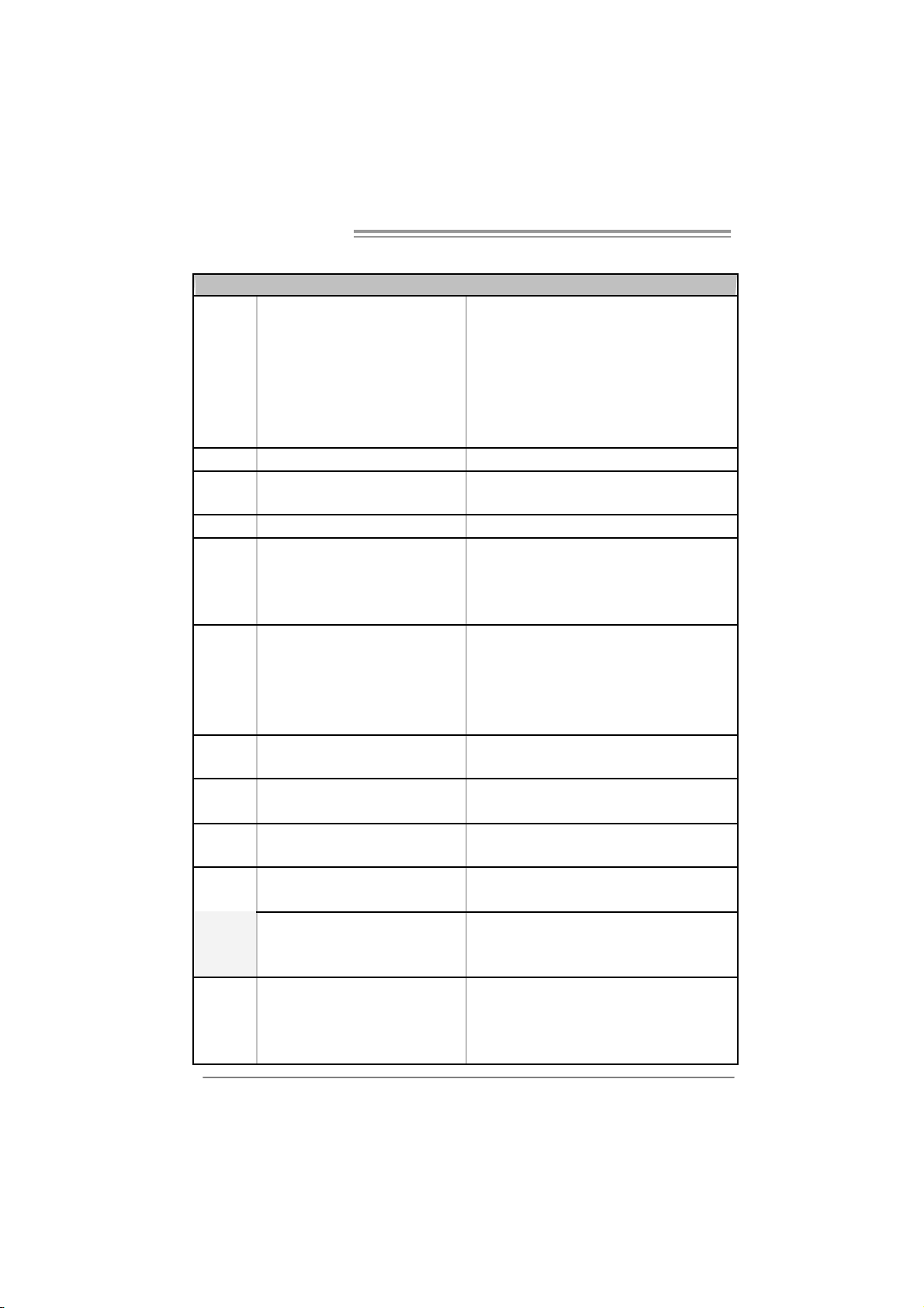
1.3 MOTHERBOARD FEATURES
SPEC
LGA 77 5
Suppor ts Intel Pentium 4 / Pe ntium D
/ Celeron D processor up to 3.8 GHz
CPU
FS B 533 / 80 0 / 106 6 MHz
Chipset
Graphic Integrated i n U niChrome Pro Chipset Max Share d Video Memory is 6 4 MB
Super I/O
Main
Memory
IDE Integrated I DE Controller
SATA Integrated Serial ATA Controller
LAN PHY Realtek RTL8201BL/RTL8201CL
Sound
Codec
On Board
Connector
Supports Intel Core2Duo processor
(onl y for Ver 2. 0 / 8.0)
*It is recommende d to use processors
with 95W power c onsumption.
VIA P4M800 PRO
VIA VT8237R+
ITE I T 87 05AF
Provides the most commonly used
legacy Super I/O functionality.
Low Pi n C ount Interf ace
DIMM Slots x 2
Support s D DR2 400 / 533
Each DIMM supports
256MB / 512M B/1GB DDR 2
Max Memory Capicity 2GB
AL C655
AGP slot x1 Supports AGP expansion cards
CNR slot x1 Supports CNR expansion cards Slots
PCI slot x3 Supports PCI expansion cards
Floppy connector x1 Each connector supports 2 Floppy drives
IDE Connector x2 Each connector supports 2 IDE device
SATA Connector x2 Each connector supports 1 SATA devices
Front Panel Connector x1 Supports front panel facilities
4
Suppor ts Hy per -Threadin g Techn ology / Execute
Disable Bit/ Enhanced Intel S peedStep® / Intel
Extended Memory 64 technology
Environment Control initiatives,
H/W Monitor
Fan S pee d Co ntroll er
ITE' s "Smart Guardia n" funct ion
Single Channel Mode DDR2 memory module
Registered DIMM and ECC DIMM is not supported
Ultra DMA 33~133 Bus Master Mode
supports PI O Mo de 0~ 4,
Data transfer rates up to 1.5 Gb/s.
SATA Version 1.0 specification compliant.
10 / 100 Mb/s auto negotiation
Half / Full duplex capability
6 channels audio out
AC ’97 Vers ion 2.3
Page 5
SPEC
Front Audi o Connec tor x1 Supports front panel audio function
CD-in Co nnec tor x1 S uppor ts C D au dio-in function
S/PDIF out connector x1 Supports di gital audio out function
CPU Fan hea der x1 C PU Fan power s upply (with Sm art Fa n f uncti on )
System Fan hea der x1 System Fan Power su pply
Chassis open header(optional) x1 For chassis intruder detection function
Cl ear CM O S head er x1 R es t ore CM O S data to factory d efa ult
USB connector x2 Each connector supports 2 front panel USB ports
Power Connector (20pin) x1 Connects to Power supply
Power Connector (4pin) x1 Connects to Power supply
PS/2 Keyb oard x1
PS/2 Mo use x1
Serial Port x1
Back Panel
I/O
Board Size 201 mm (W ) x 244 mm (L) Mic ro ATX for m Fac tor
Special
Features
OS
Suppor t
Printer Port x1
VGA Port x1
LAN port x1
USB Port x4
Audio Jack x3
RAID 0 / 1 support
Windows 2000 / XP
Connects to PS/2 Keyboard
Connects t o PS / 2 Mo use
Provide RS - 232 S erial connec tion
Connects to various types of device
Connects to monit or.
Connects to RJ-45 ethernet cable
Connects to USB devices
Provide Audio-In/O ut a nd mic roph one c o nnect ion
Biostar Reserves the right to add or remove
support for any OS with or without notice.
P4M800 Pro-M7
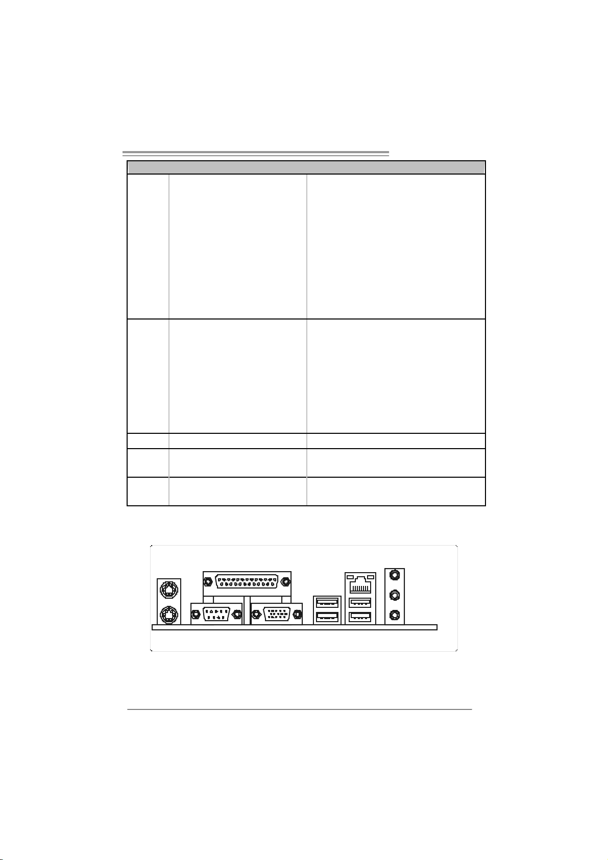
1.4 REAR PANEL CONNECTORS
PS/2
Mou se
PS/2
Keyboa rd
Pr inter Port
COM1 VGA1 USBX2USBX2
LAN
Line In/
Sur round
Line Out
Mic In 1/
Bass/ Center
5
Page 6
Motherboard Manual
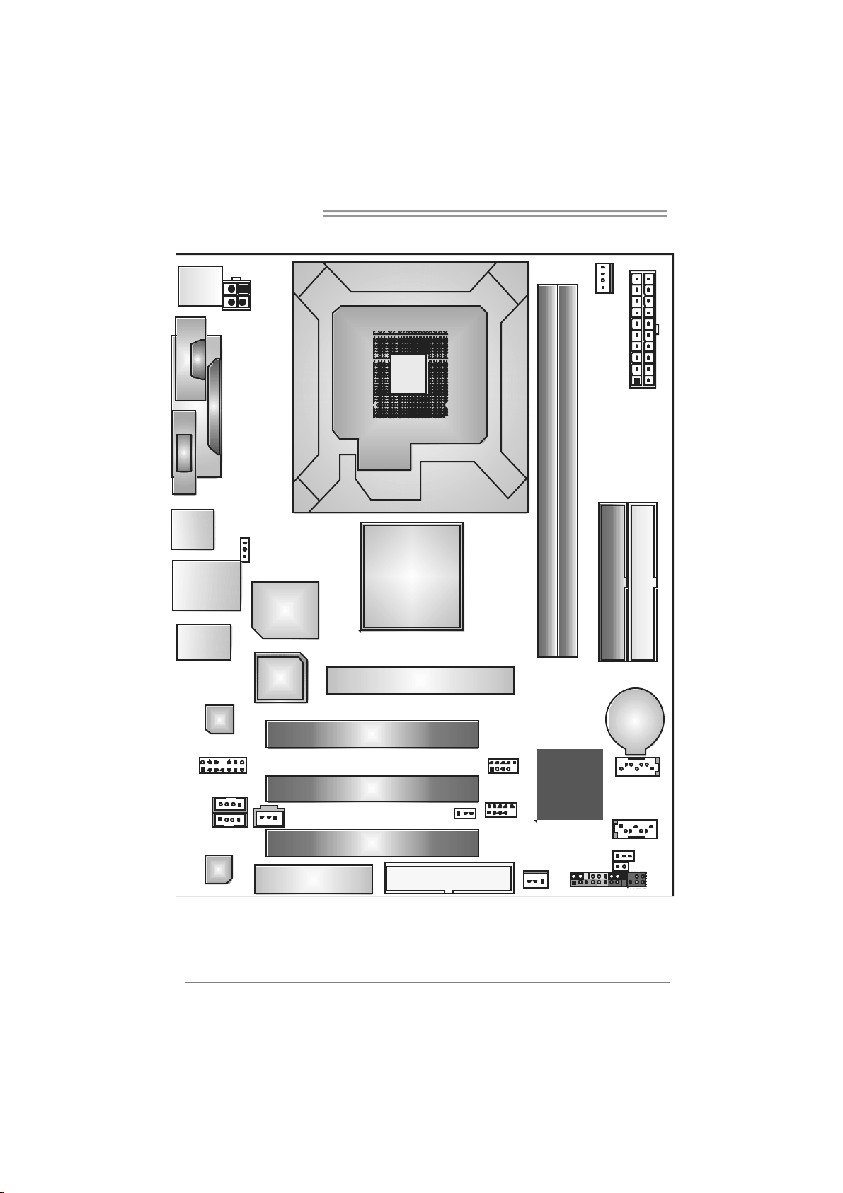
1.5 MOTHERBOARD LAYOUT
JKBMS1
J
C
O
M
1
JVGA1
JUSB1
JUSBLAN1
JAUDIO1
JATXPW R2
JPRNT1
J US BV1
Super
BIOS
I/O
LGA77 5
CPU1
P4M800 Pro
AGP1
JC FAN1
JATXPWR1
DDR2_A2
DDR2_A1
IDE1
IDE2
JCDIN 1
(opti onal)
6
JFAUDIO1
JAUX1
Codec
LAN
Note: represents the 1■
JSPDIFO1
CNR1
PCI1
PCI2
PCI3
st
pin.
JUSBV2
FDD1
JU SB 2
JUSB3
VT8237R
PLUS
JSFAN1
JPAN EL1
BAT1
JSAT A2
JSAT A1
JCMOS1
JC I1
IR (optional)
(option al)
Page 7
P4M800 Pro-M7
CHAPTER 2: HARDWARE INSTALLATION
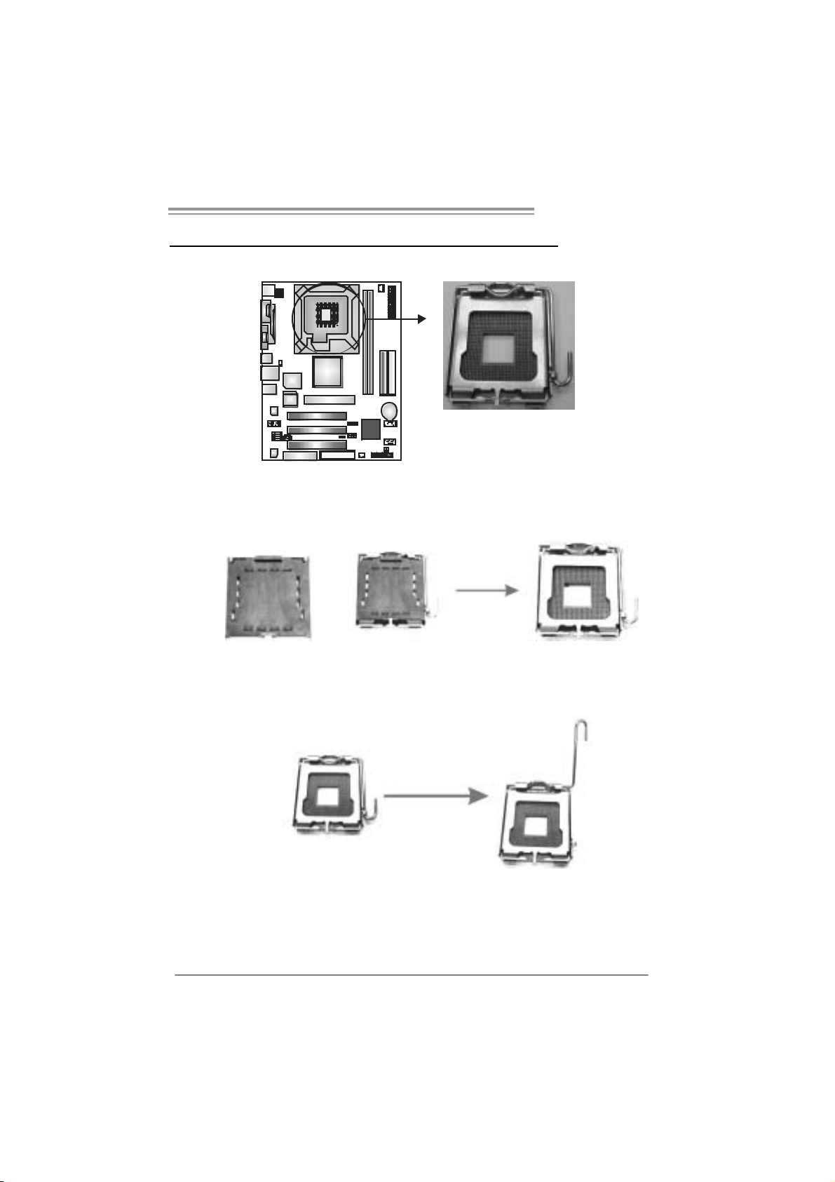
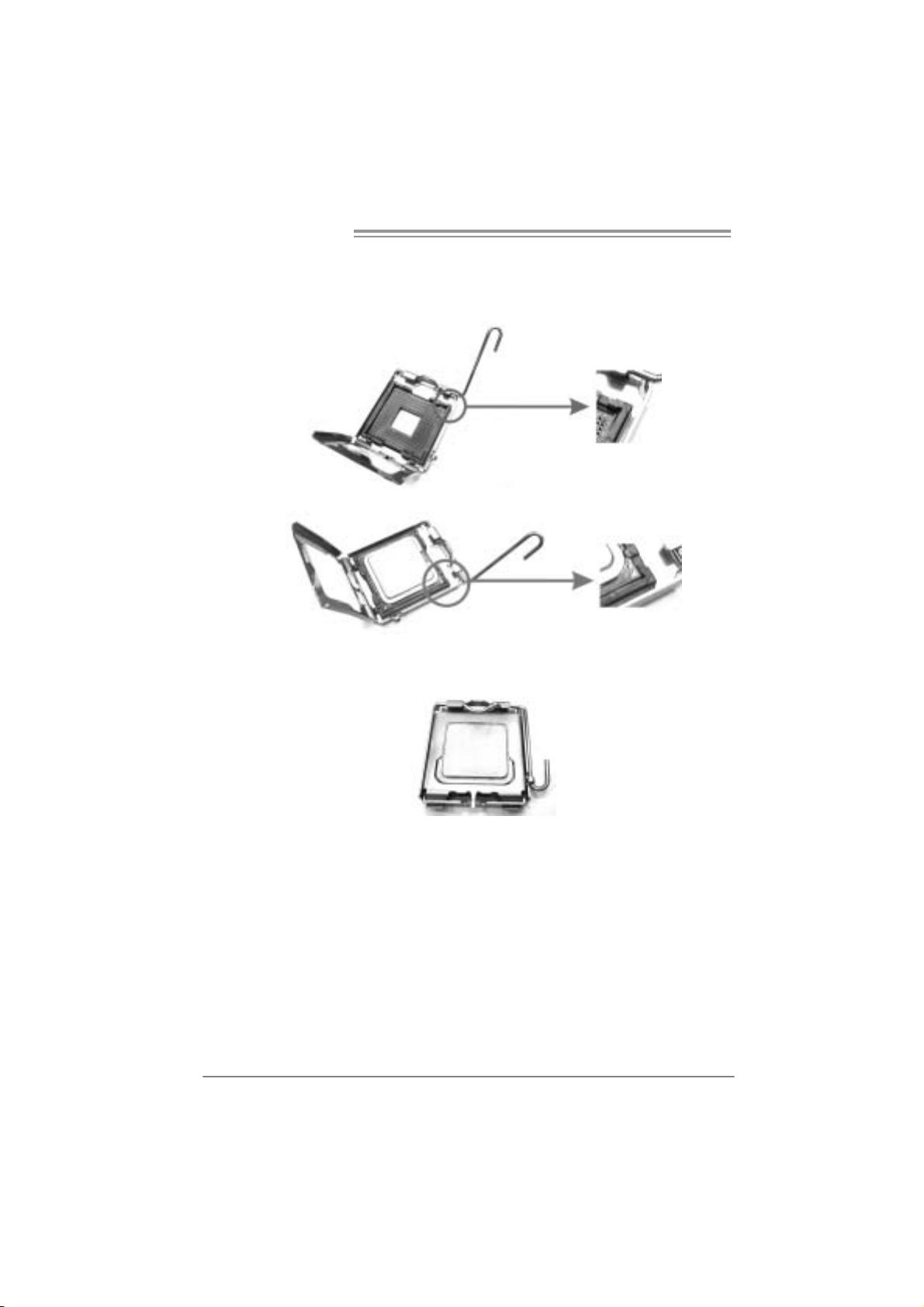
2.1 INSTALLING CENTRAL PROCESSING UNIT (CPU)
Special Notice:
Remo v e Pin Cap before installation, a nd make go o d preserv a tion
for future use. When the CPU is removed, cover the Pin Cap on the
empty so cket to ensure pin legs won’ t be dama g ed.
Pin Cap
Step 1: Pull the socket locking lever out from the socket and then raise
the lever up to a 90-degree angle.
7
Page 8
Motherboard Manual
Step 2: Look for the triangular cut edge on socket, and the golden dot on
CPU should point forwards this triangular cut edge. The CPU will
fit only in the correct orientation.
Step 2-1:
Step 2-2:
Step 3: Hold the CPU down firmly, and then lower the lever to locked
posi tion to complete the installatio n.
Step 4: Put the CPU Fan and heatsi nk assembly on the CPU and buckle i t
on the retention frame. Connect the CPU FAN power cable into
the JCFAN1. This completes the installation.
8
Page 9
P4M800 Pro-M7
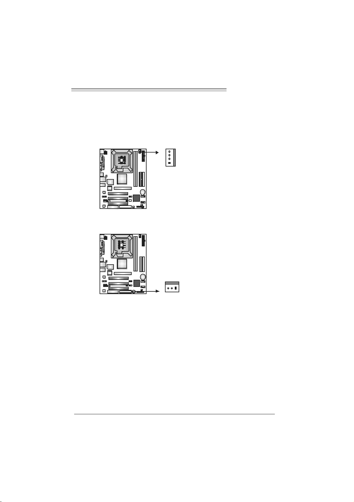
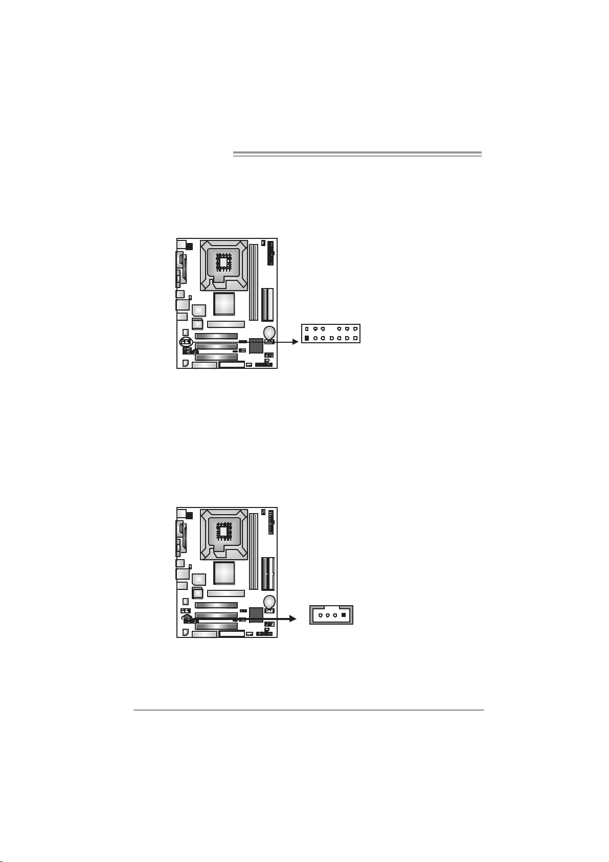
2.2 FAN HEADERS
These fan headers support cooling-fans built in the computer. The fan
cable and connector may be different according to the fan manufacturer.
Connect the fan cable to the connector while matching the black wire to
pin#1.
JCFAN1: CPU Fan Heade r
Pin
Assignment
1 Ground
2 +12V
3 FAN RPM rate
sense
4 Smart Fan
Control
Pin
Assignment
1 Ground
2 +12V
3 FAN RPM rate
sense
JSF AN1 : Syst em F an H ead er
Note:
The JSFAN1 s upport 3-pi n head connec tor. When c onnecting with wires onto connectors,
please note that the red wire is the positive and should be connected to pin#2, and the
black wire is Ground and should be connected to GND.
4
1
JCFAN1
JSFAN1
13
9
Page 10
Motherboard Manual
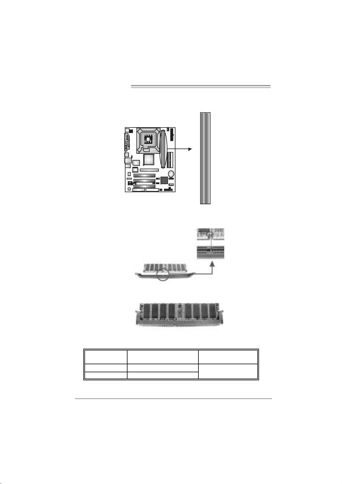
2.3 INSTALLING SYSTEM MEMORY
A. Me mo ry Mo du le s
DDR2_A1
DDR2_A2
1. Unlock a DIMM slot by pressing the retaining clips outward. Align a
DIMM on the slot such that the notch on the DIMM matches the
break on the Slot.
2. Insert the DIMM vertically and firmly into the slot until the retaining
chip snap back in place and the DIMM is properly seated.
B. Memory Capacity
DIMM Socket
Location
DDR2_A1 256MB/512MB/1GB
DDR2_A2 256MB/512MB/1GB
DDR Module
Total Memory Size
Max i s 2 G B.
10
Page 11
P4M800 Pro-M7
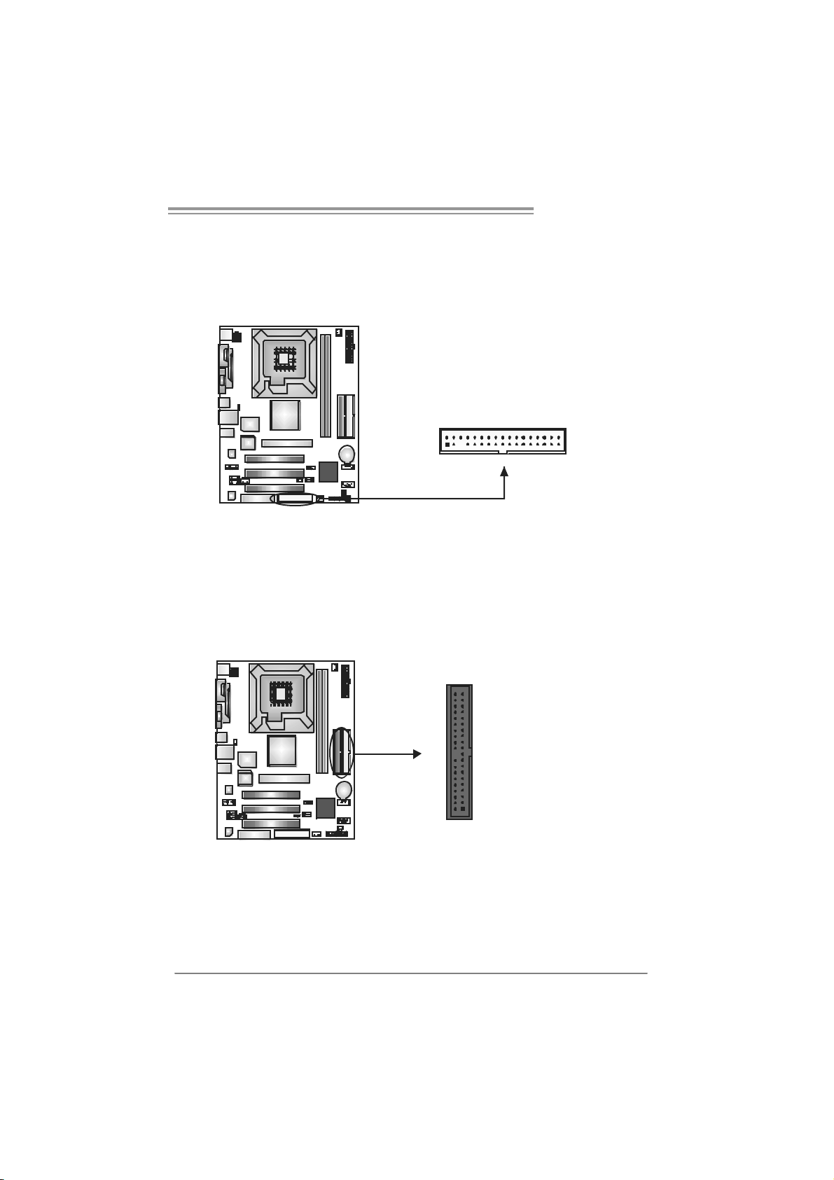
2.4 CONNECTORS AND SLOTS
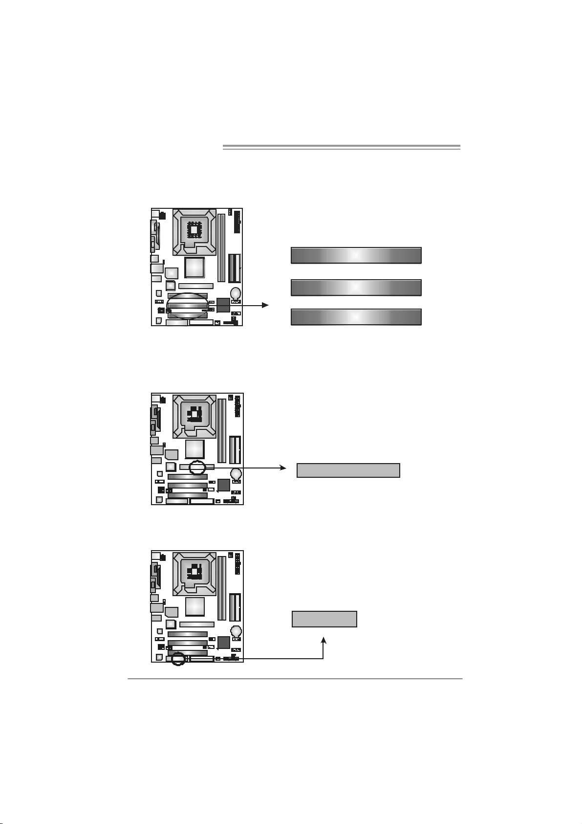
FDD1: Floppy Disk Connecto r
The motherboard prov ides a standard floppy disk connector that supports 360K,
720K, 1. 2M, 1.44M and 2. 88M floppy disk ty pes. This connect or supports the
provided f loppy drive ribbon cables.
IDE1/IDE2: H ard Disk Connec tors
The motherboard has a 32-bit Enhanced PCI ID E Controller that prov ides PIO
Mode 0~4, Bus Mas t er, and Ult ra D MA 33/66/ 100/ 133 funct ionality. It has two
HDD connect ors ID E1 (primary) and IDE2 (secondary).
The IDE connectors can connect a m aster and a slave driv e, so you can
connec t up to four hard disk drives. The first hard driv e should always be
connec t ed to IDE1.
2
1
3940
21
34
33
IDE2IDE1
11
Page 12
Motherboard Manual
A
PCI1~PCI3: Pe riphe ral Component In terconnect Slo ts
This mot herboard is equipped with 3 standard PCI slots. PCI stands f or
Peripheral Com ponent Int erconnect, and it is a bus standard for expansion
cards . This PCI slot is designated as 32 bits.
AGP1 : Accelerate d Graph i cs Port S l ot
Your monit or will attach directly to that video card. This motherboard supports
video c ards for PCI slots, but it is also equipped with an Accelerat ed Graphics
Port (AGP). An AGP card will tak e adv antage of AGP t ec hnology for improved
video efficiency and performance, espec ially with 3D graphics.
PCI1
PCI2
PCI3
CNR1: Co m m unication Ne twork Rise r Slot
The CNR specification is an open Industry Standard Arc hit ecture, and it def ines
a hardware scalable riser card interfac e, which supports modem only .
12
GP1
CNR1
Page 13
P4M800 Pro-M7
CHAPTER 3: HEADERS & JUM PERS SETUP
3.1 HOW TO SETUP JUMPERS
The illustration shows how to set up jumpers. When the jumper cap is
placed on pins, the jumper is “close”, if not, that means the j umper is
“open”.
Pin opened Pin closed Pin1-2 closed
3.2 DETAIL SETT INGS
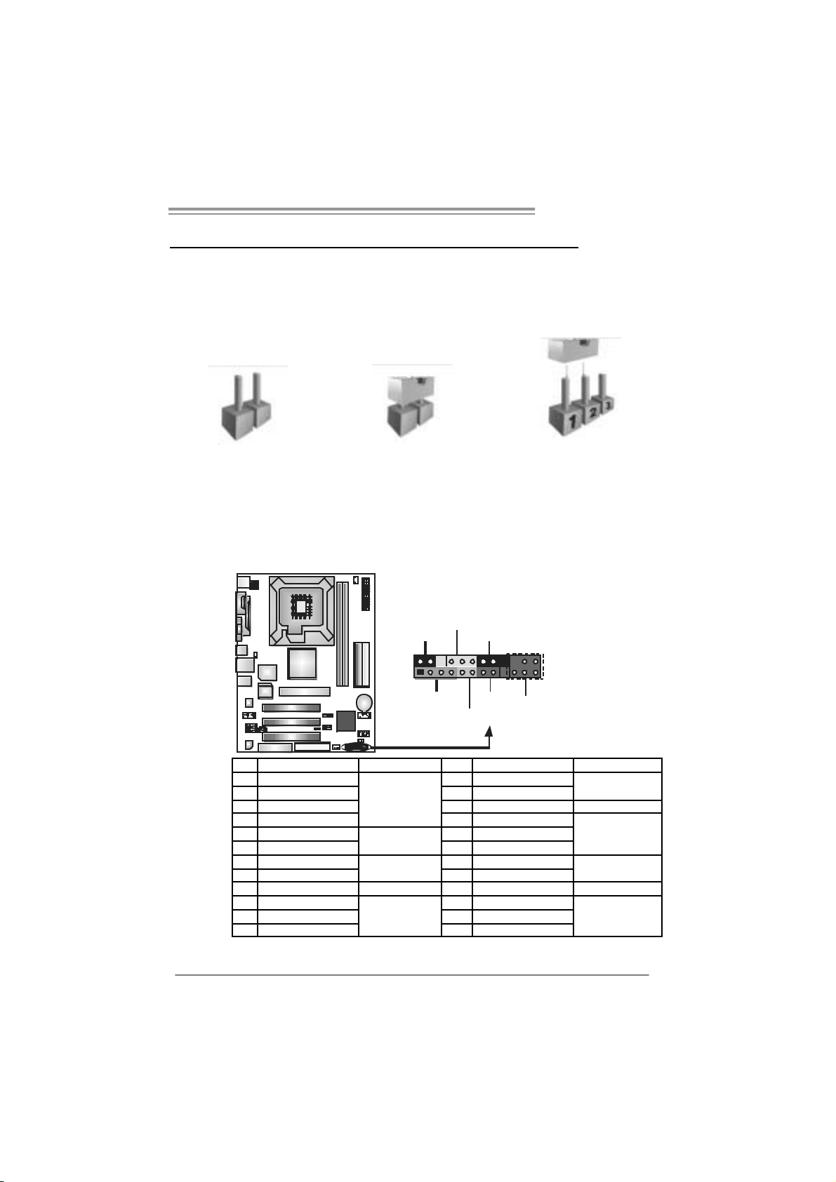
JPANEL1: Front Panel Header
This 24-pin connector includes Power-on, Reset, HDD LED, Power LED, Sleep
butt on, speaker and IrDA Connection. It allows user to connect the PC case’s
front panel switch fun ctions.
PWR_LED
SLP
2
123
SPK
++
+
HLED
On/Of f
-
RST
24
I R ( optional)
Pin Assignment Functio n P in Ass ignment Functio n
1 +5V 2 Sleep control
3 N/A 4 Ground
5 N/A 6 N/A N/A
7 Speaker
9 HDD LED (+) 10 Power LED (+)
11 HDD LED (-)
13 Ground 14 Power button
15 Reset control
17 N/A 18 N/A
19 N/A 20 Key
21 +5V 22 Ground
23 IRTX
Speaker
Connector
Hard drive LED
Reset button
IrDA Connector
(optional)
8 Power LED (+)
12 Power LED (-)
16 Ground
24 IRRX
Sleep button
Powe r LED
Power-on button
IrDA Connector
(optional)
13
Page 14
Motherboard Manual
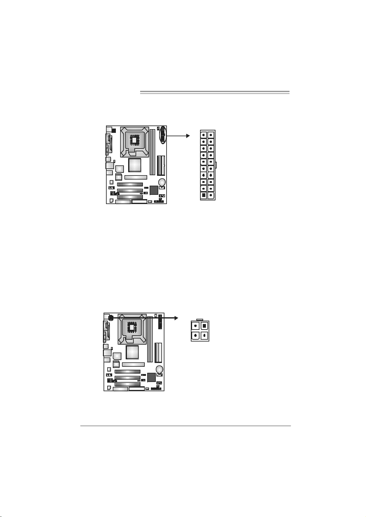
JAT XPWR1: ATX Powe r Sou rce Co nnector
This connector allows user to connect 20-pin power c onnector on the ATX
power supply.
10 20
111
Pin Assignment Pin Ass ignment
1 +3.3V 11
2 +3.3V 12
3 Ground 13
4 +5V 14
5 Ground 15
6 +5V 16
7 Ground 17
8 PW_OK 18
9 Standby Voltage +5V 19
10 +12V 20
+3.3V
-12V
Ground
PS_ON
Ground
Ground
Ground
-5V
+5V
+5V
JAT XPWR2: ATX Powe r Sou rce Co nnector
By c onnecting this connector, it will prov ide +12V to CPU power c irc uit.
12
Pin
34
Assignment
1 +12V
2 +12V
3 Ground
4 Ground
14
Page 15
P4M800 Pro-M7
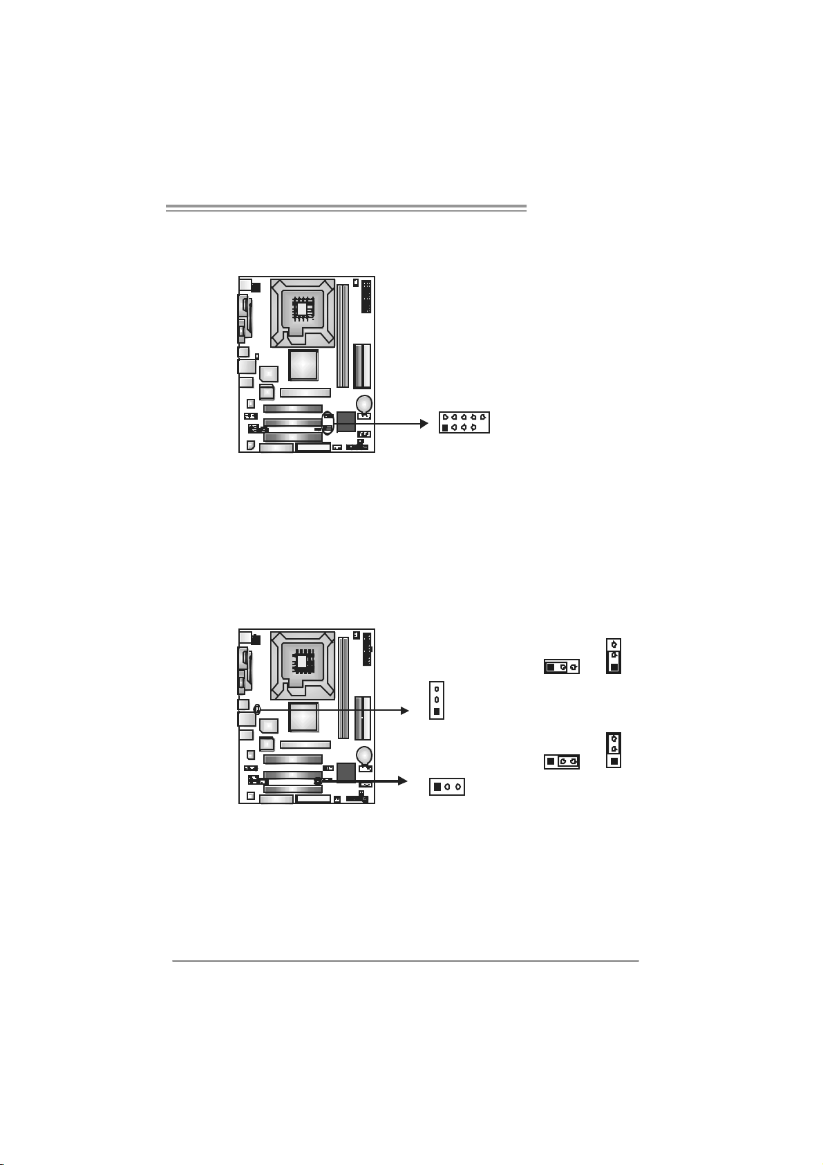
JU S B2/JUSB 3: H ead er s for U SB 2. 0 P orts at Fr o nt Pa ne l
This header allows user to connect additional USB cable on the PC front panel,
and also can be connected with internal USB devices, like USB card reader.
Assignment
Pin
1 +5V (fused)
2 +5V (fused)
3 USB4 USB5 USB+
6 USB+
7 Ground
10
9
JUSB2
JUSB3
2
1
JUSBV1/ JUSBV2 : Power Source H eade rs for USB ports
Pin 1-2 Close:
JU SBV1: +5V for U SB port s at JUSB1 and JUSBLAN 1.
JU SBV2: +5V for U SB port s at front panel (JUSB2/JU SB3).
Pin 2-3 Close:
JU SBV1: USB ports at JU SB1 and J U SBLAN1 are powered by +5V
standb y voltage.
JU SBV2: USB ports at front panel (JU SB2/JUSB3) are powered by +5V
standb y voltage.
8 Ground
9 Key
10 NC
3
31
1
3
1
3
1
JUSBV1
13
JUSBV2
Pin 1-2 close (Default)
Pin 2-3 close
1
3
Note:
In order to support this f unction “Power-On system via USB dev ice,” “JUSBV1/ JUSBV2”
jumper cap should be plac ed on Pin 2-3 indi viduall y.
15
Page 16
Motherboard Manual
JFAUDIO 1 : Front Panel Audio Header
This header allows user to connect t he front audio output cable with the PC front
panel. It will disable the output on back panel audio connectors.
Pin Assignment
1 Mic-in/Stereo MIC-in
R
2 Ground
3 Stereo MIC-in L
4 Audio power
5 Right line-out/
Speaker-out Right
6 Right line-out/
Speaker-out Right
2
1
14
13
7 Reserved
8 Key
9 Left line-out/
Speaker-out Left
10 Left line-out/
Speaker-out Left
11 Right line-in (optional)
12 Right line-in (optional)
13 Left line-in (optional)
14 Left line-in (optional)
JCDIN1: CD-R OM A ud io-in Connector
This connector allows user to connect the audio s ourc e f rom the v ariaty dev ices,
like CD-R OM, DVD-ROM, PCI sound card, PCI TV turner card etc.
16
Pin
Assignment
1 Left Channel Input
2 Ground
3 Ground
4 Right Channel Input
14
Page 17

P4M800 Pro-M7
JCMOS 1 : C l ea r CMO S He ader
By plac ing the jumper on pin2-3, it allows user to restore the BIOS saf e sett ing
and the CMOS dat a, please carefully follow the procedures to avoid damaging
the m otherboard.
Pin 1-2 Close:
Normal Operation (default).
13
Pin 2-3 Close:
Clear CMOS data.
※ Clear CMOS Procedures:
1. Rem ove AC power line.
2. Set the jumper to “Pin 2-3 close”.
3. Wa i t fo r five se co n ds.
4. Set the jumper to “Pin 1-2 close”.
5. Power on t he AC.
6. Res et your des ired pas s word or clear t he C MOS data.
31
1
3
JSATA1~JS ATA2: Serial ATA Connectors
The motherboard has a PCI to SATA Cont roller with 2 channels SATA interfac e,
it satisfies the SATA 1.0 spec and with transfer rate of 1.5Gb/s.
Pin
Assignment
1 Ground
2 TX+
3 TX4 Ground
5 RX-
JSATA2
147
JSATA1
6 RX+
7 Ground
17
Page 18

Motherboard Manual
JSPDIFO1: Digital Audio-out Connector
This connector allows user to connect the PCI bracket SPDIF output header.
JCI1: Chassis Open Header (optional)
This connector allows system to monitor PC cas e open stat us. If the signal has
been triggered, it will record to the CMOS and s how the message on next
boot-up.
Pin
Assignment
1 +5V
2 SPDIF_OUT
3 Ground
13
Pin
Assignment
1 Case open signal
2 Ground
18
12
Page 19

P4M800 Pro-M7
CHAPTER 4: RAID FUNCTIONS
4.1 OPERATION SYSTEM
Supports Windows XP H om e/Professional Edition, and Windows 2000 Professional.
4.2 RAID ARRAYS
RAI D supports the following types of R AID arrays:
RAID 0: RAID 0 defines a disk striping scheme that improves disk read and write times for
many applications.
RAID 1: RAID 1 defines techniques for mirroring data.
4.3 HOW RAID WORKS
RAID 0:
The controller “stripes” data across multiple drives in a RAID 0 array system. It breaks
up a large file into smaller blocks and performs disk reads and writes across multiple
drives in parallel. The size of each block is determined by the stripe size parameter,
which you set during the creation of the RAID set based on the system environment. This
technique reduces overall disk access time and offers high bandwidth.
Fea tures and Be nefits
Drives: Minimum 1, and m ax imum is up to 6 or 8. Depending on the
platform.
Uses: I ntended for non-critical data requiring high dat a throughput, or any
environment that does not require f ault toleranc e.
Benefits: prov ides inc reas ed dat a t hroughput, es pec ially for large files. No
capac ity loss penalty f or parity.
Drawbacks: Does not deliver any fault tolerance. If any drive in the array
fails, all dat a is lost.
Fault To le rance : No.
Blo c k 1
Bl o ck 3
Bl o ck 5
Bl o ck 2
B lock 4
B lock 6
19
Page 20

Motherboard Manual
RAID 1:
Every read and write is actually carried out in parallel across 2 disk drives in a RAID 1
array system. The mirrored (backup) copy of the data can reside on the same disk or on
a second redundant drive in the array. RAID 1 provides a hot-standby copy of data if
the active volume or drive is corrupted or becomes unavailable because of a hardware
failure.
RAID techniques can be applied for high-availability solutions, or as a form of
automatic backup that eliminates tedious manual backups to more expensive and less
reliable media.
Fea tures and Be nefits
Drives: Minimum 2, and max imum is 2.
Uses: RAID 1 is ideal f or small databases or any other applicat ion that
requires f ault tolerance and minimal ca paci t y.
Benefits: Provides 100% data redundancy. Should one drive f ail, t he
controller switche s to the o ther dri ve.
Drawbacks: Requires 2 drives for the st orage space of one driv e.
Performance is impaired during driv e rebuilds.
Fa ult To le rance : Yes.
20
Blo c k 1
Bl o ck 2
Bl o ck 3
Block 1
Bl o ck 2
Bl o ck 3
Page 21

P4M800 Pro-M7
CHAPTER 5: USEFUL HELP
5.1 DRIVER INSTALL ATION NOTE
After you installed your operating system, please insert the Fully Setup
Driver CD into your optical drive and install the driver for better system
performance.
You will see the following window after you insert the CD
The set up guide will auto detect yo ur motherboard and operating syst em.
Note:
If this window didn’t show up after you insert the Driver CD, please use file browser to
l ocate and execut e th e fil e SETU P.EXE under yo ur o pt ic al dr i ve.
A. Driver Installation
To install the driver, please click on the Driver icon. The setup guide will
list the compatible driver for your m otherboard and operating system.
Click on each devi ce driver to launch the installation program.
B. Software Installatio n
To install the software, please click on the Software icon. T he setup guide
will list the software available for your system, click on each software title
to la unch th e ins ta l lat io n pr ogr am.
C. Manual
Asi de from the paperback manual, we also provi de manual in the Driver
CD. Click on the Manual icon to browse for available manual.
Note:
You will need A c rob at Reader to open the man ua l file . Please download the latest version
of Acrobat Reader software from
http://www.adobe.com/products/acrobat/readstep2.html
21
Page 22

Motherboard Manual
5.2 AWARD BIOS BEEP CODE
Beep Sound Meaning
One long beep followed by t wo short
beeps
High-low siren sound CPU overheated
One Short beep when system boot-up N o error f ound during POST
Long beeps every ot her second No DRAM detected or ins t all
Video card not found or v ideo card
mem ory bad
Sys t em will s hut down automat ically
5.3 EXT RA INFORMATION
A. BIOS Update
After yo u fail to update BIOS or BIOS i s invaded by virus, the
Boot-Block functi on will help to restore BIOS. If the fol lowing message
is shown after boot-up the system, it means the BIOS contents are
corrupted.
In this Case, please follow the procedure below to restore the BIOS:
1. Make a bootab le floppy d is k.
2. Download the Flash Utility “AWDFLASH.exe” from the Biostar
website: www.biostar.com.tw
3. Confirm motherboard model and download the respectively BIOS
fr om Bi os t ar w ebs ite.
4. Copy “AWDFLASH.exe” and respectively BIOS into floppy disk.
5. Insert the bootable disk into floppy drive and press Enter.
6. Sy stem will boot-up t o DOS p romp t.
7. Type “Aw dflash xxxx.bf / sn/py/ r” in DOS prompt.
(xxxx means B IOS name.)
8. Sy stem will update BIOS au tomatic ally an d re start.
9. The BIOS ha s bee n re cov ered an d will wo rk properly.
22
Page 23

P4M800 Pro-M7
B. CPU Overheated
If the system shutdown automatically after power on system for
seconds, that means the CPU protection function has been acti vated.
When the CPU is over heated, the motherboard wi ll shutdown
automatically to avoid a damage of the CPU, and the system may not
power on again.
In this case, please double check:
1. The CPU cooler surface is placed evenl y with the CPU surface.
2. CPU fan is rotated norm all y.
3. CPU fan speed is fulfilling wi th the CPU speed.
After confirmed, please follow steps below to relief the CPU protecti on
function.
1. Remove the power cord from power supply for seconds.
2. Wai t for seconds.
3. Plug in the power cord and boot up the system.
Or you can:
1. Clear the CMOS data.
(See “Close CMOS Header: JCMOS1” section)
2. Wai t for seconds.
3. Power on the system again.
23
Page 24

Motherboard Manual
e
5.4 TROUBLESHOOTING
Probable Solution
1. N o power to t he system at all
Power light don’t illuminate, fan
inside power supply does not turn
on.
2. I ndic at or light on keyboard does
not t urn on.
Sys t em inoperativ e. Keyboard lights
are on, power indicat or lights are lit,
and hard drive is spinning.
Sys t em does not boot from hard dis k
drive, can be booted from optic al driv e.
Sys t em only boots f rom optic al driv e.
Hard disk can be read and applications
can be used but booting from hard disk
is imposs ible.
Screen m essage says “Invalid
Conf igurat ion” or “C MOS Failure.”
Cannot boot syst em aft er installing
sec ond hard driv e.
1. Make s ure power cable is
sec urely plugged in.
2. Replace cable.
3. Contact technical support.
Us ing even press ure on bot h ends of
the DIMM, press down f irm ly until the
module s naps into place.
1. C hec k cable running f rom disk t o
disk controller board. Make sure
both ends are sec urely plugged
i n; check t he driv e t y pe in t he
standard CMOS setup.
2. Bac k ing up t he hard driv e is
ext rem ely import ant. All hard
disk s are capable of breaking
down at any t ime.
1. Bac k up dat a and applic at ions
files.
2. R eformat the hard driv e.
Re-ins t all applications and data
using backup disks.
Rev iew syst em’s equipment. Make sur
correc t information is in set up.
1. Set m as t er/ s lav e jum pers
correctly.
2. R un SETUP program and s elec t
correc t drive types. Call the drive
manufacturers for co mpatibilit y
with other drives.
24
Page 25

P4M800 Pro-M7
CHAPTER 6: WARPSPEEDER™
6.1 INTRODUCTION
[WarpSpeeder™], a new powerful control utility, features three
user-friendly functions including Overclock Manager, Overvoltage
Manager, and Hardware M onitor.
With the Overclock Manager, users can easily adjust the frequency they
prefer or they can get the best CPU performance wi th just one click. T he
Overvoltage Manager, on the other hand, helps to power up CPU core
vol tage and Me mor y v ol ta ge. Th e co o l H ar dware Mo ni tor s mar t ly in d ic at es
the tem peratures, voltage and CPU fan speed as well as the chi pset
information. Also, in the About panel, you can get detail descriptions about
BIOS model and chipsets. In addition, the frequency status of CPU,
memory, AGP and PCI along with the CPU speed are synchronically
s how n on our ma i n p an el .
Moreover, to protect users' computer systems i f the setting is not
appropriate when testing and results in system fail or hang,
[WarpSpeeder™] technology assures the sy stem stability by automatically
rebooting the computer and then restart to a speed that is either the
original system speed or a suitable one.
6.2 SYS TEM REQUIREMENT
OS Support: Wi ndows 98 SE, Windows M e, Wi ndows 2000, Windows XP
DirectX: DirectX 8.1 or above. (The Windows XP operating system
includes DirectX 8.1. If you use Windows XP, you do not need to install
Dir ec tX 8.1.)
25
Page 26

Motherboard Manual
6.3 INSTALLATION
1. Execute the setup execution file, and then the following dialog will pop
up. Please click “Next” button and follow the default procedure to
install.
2. When you see the following dialog in setup procedure, it means setup
is completed. If the “Launch the WarpSpeeder Tray Uti lity” checkbox
is che c ked, the Tray Ic on utility an d [ WarpSp eeder™] utility will be
automatically and immediately launched after you click “Finish”
button.
26
Usage:
The following figures are just only for reference, the screen printed in
this use r man ual will chan ge ac c ord ing to your mothe rbo ard on hand.
Page 27

6.4 WARPSPEEDER™
1. Tray Icon:
Whenever the Tray Icon utility i s launched, it will di splay a little tray
icon on the right side of Windows Taskbar.
This utility is responsible for conveniently invoki ng [WarpSpeeder™]
Utility. You can use the mouse by clicking the left button in order to
invoke [WarpSpeeder™] directly from the littl e tray icon or you can
right-click the little tray icon to pop up a popup menu as following
figure. The “Launch Utility” item in the popup menu has the same
fun c tion as mo use left-c lic k on tray icon and “Exit ” item will close
T ray Icon utility if sel e cted.
P4M800 Pro-M7
27
Page 28

Motherboard Manual
2. Main Panel
If y ou click the t ray icon, [WarpSpe ed er™] util ity will b e invo ked.
Please refer to the following figure; the utility’s first wi ndow you will
see is Main Panel.
Main Panel contains features as foll ows:
a. Di spl ay the CPU Spe ed, CPU e xtern al clock, Mem ory cl ock, AGP cl ock,
and PCI clock inform ation.
b. Contains About, Voltage, Overclock, and Hardware Monitor Buttons for
invoki ng respective panels.
c. With a user- fr ie nd ly St at us Anim atio n, it c an represent 3 overcl oc k
percentage stages:
Man walking→overclock percentage from 100% ~ 110 %
Panther running→overclock percentage from 110% ~ 120%
Ca r rac ing→overclock percentage from 120% ~ above
28
Page 29

P4M800 Pro-M7
3. Vol tage Panel
Click the Voltage button in Main Pa nel, the b ut ton will be hig hlighte d
and the Vol tage Panel will sl ide out t o up as the f ollo wing fig ure .
In this panel, you can deci de to increase CPU core voltage and
Memory voltage or not. The default setting is “No”. If you wan t to get
the best performance of overcl ocking, we recommend you click the
option “Yes”.
29
Page 30

Motherboard Manual
4. Over clock Panel
Click the O verclock bu tton in Ma in Pane l, the button will be
highlighted and the Overclock Panel will slide out to left as the
fol l owi ng f igur e.
Overclock Panel contains the these features:
a. “–3MHz button”, “-1MHz button”, “+1MHz button”, and “+3MHz button”:
provide user the ability to do real-time overcl ock adjustment.
Warning:
Manually overclock is potentially dangerous, especially when t he
overclocking percentage is over 110 %. We st rongly recommend you
verify ev ery speed you overc lock by c lick the Verify button. Or, you can
just click Auto ov erclock butt on and let [WarpSpeeder™] autom atically
gets the best result f or y ou.
b. “Recovery Dialog button”: Pop up the following dialog. Let user select
a restoring way if system need to do a fail-safe reboot.
30
Page 31

P4M800 Pro-M7
c. “Auto-overclock button”: User can click thi s button and
[Wa rpS peede r™ ] will se t the best and stable performan ce an d
frequency automatically. [WarpSpeeder™] utility will execute a
se ries of testing until system fail. Then system will do fail-saf e
reboot by using Watchdog function. After reboot, the
[WarpSpeeder™] utility will restore to the hardware default
setting or load the veri fied best and stabl e frequency according
to the Recovery Di alog’s setti ng.
d. “Verify button”: User can click this button and [WarpSpeeder™]
will proceed a testi ng for current frequency. If the testing is ok,
then the current frequency will be saved into syste m registry. If
the testing fail, system will do a fail-safe rebooting. After reboot,
the [WarpSpe eder™ ] utility will rest ore to th e h ard ware defau lt
setting or load the veri fied best and stabl e frequency according
to the Recovery Di alog’s setti ng.
Note:
Becaus e the testing programs, invok ed in Aut o-overclock and Verify,
include D irectDraw, Direct3D and DirectShow tests, the DirectX 8.1 or
newer runtime library is required. And please make sure your display
card’s color depth is High color (16 bit ) or True color( 24/32 bit ) that is
required for Direct3D rendering.
5. Hardware Monitor Panel
Click the Ha rdwa re Mo nitor button in Ma in Pane l, the bu tton will be
highlighted and the Hardware Monitor panel will slide out to left as
the fo l lowing fig ur e.
In this panel, you can get the real-time status inform ation of your
syste m. The informatio n will be refreshed every 1 second.
31
Page 32

Motherboard Manual
6. About Panel
Click the “about” button in Main Panel, the button will be highlighted
and th e A b out Panel will s l id e out to up as the fo l lowin g f igur e.
In this panel, you can get model name and detail inform ation in hints
of all the chipset that are related to overclocki ng. You can also get
the mainboard’s BIOS model and the Version number of
[WarpSpeeder™] utility.
32
Note:
Because the overclock, overvoltage, and hardware monitor features
are controlled by several separate chipset, [WarpSpeeder™] divide
these features to separate panels. If one chipset is not on board, the
cor r elative but ton i n M ain panel will be disabled, but will not interfer e
other panels’ functi ons. This property can make [WarpSpeeder™]
utility more robust.
Page 33

P4M800 Pro-M7
This page i s intentionally left blank
33
Page 34

Motherboard Manual
APPENDENCIES: SPEC IN OTHER LANGUAGE
GERMAN
Spezifikationen
LGA 77 5
Intel Pentium 4 / Pentium D /
Celeron D Prozess oren mit bis z u 3,8
GHz
CPU
FS B 533 / 80 0 / 106 6 MHz
Chipsatz
Grafik Integrierter UniChrome Pro C hipsatz Max. 64MB gemeinsam ben utzt er Videospeic her
Super E/A
Arbeitsspeic
her
IDE Integrierter IDE-Controller
SATA Integrierter Serial ATA-Controller
LAN PHY Realtek RTL8201BL/RTL8201CL
Audio-Code
c
Steckplätze
Int el Core2 Duo Proz es s oren ( nur für
Ver 2. 0 / 8.0)
*It is recommended to use
proc es sors with 95W power
consumpt ion.
VIA P4M800 PRO
VIA VT8237R+
ITE I T 87 05AF
Biet et die h äufig verwe ndete n alten
Super E/A-Funktionen.
Low Pi n C ount-Sc hnitt stelle
DDR2 DIMM-Stec kplätze x 2
Unterstützt DDR2 400 / 533
Jeder DIMM unterstützt
256/512MB /1GB DDR2.
Max. 2GB Arbeitsspeicher
AL C 655
AGP-Steckplatz x1
CNR-Steckplatz x1
PCI-Steckplatz x3
34
Unterstützt Hyper -T hreading / Execute Dis a ble Bit
/ Enhanced Intel SpeedStep® / Extended
Memory 64 Technology
Umgebungskontrolle,
Hardware-Überwachung
Lüfterdrehzahl-Controller
"Smart Guar dian" -Funktion von ITE
Ein-Kanal DDR 2 S peic hermodul
registrierte DIMMs. ECC DIMMs werden nicht
unters tütz t.
Unterstützt PIO-Modus 0~4,
Ultra DMA 33 / 66 / 100 / 133Bus Master-Modus
Konform mit der SATA-Spezifikation Version 1.0.
Datentrans ferr ate bis z u 1.5Gb/s
10 / 1 00 Mb/s A uto-Negotiation
Halb-/ Vollduplex-Funktion
6-Kanal-Audioausg abe
AC ’97 Vers ion 2.3
Page 35

Onboard-A n
schluss
Rückseiten-
E/A
Platinengrö
ße.
Sonderf unkt
ionen
OS-Unterst
ützung
P4M800 Pro-M7
Spezifikationen
Diskettenlaufwerkanschluss x1 Jeder Anschluss unterstützt 2 Diskettenlaufwerke
IDE-Anschluss x2 Jeder A nschluss unterstützt 2 IDE-Laufwerke
SATA-Anschluss x2 Jeder A nschluss unterstützt 1 SATA-Laufwerk
Fronttafelanschluss x1 Unterstützt die Fronttafelfunktionen
Front-Audioanschluss x1
CD-IN-Anschluss x1 Unterstützt die CD Audio-In-Funktion
S/PDIF-Aus gan gsanschluss x1 Unters tüt zt die di gitale Audi oaus g abe funkt ion
CPU-Lüfter-Sockel x1
System-Lüfter-Sockel x1 System-Lüfter-Stromversorgungsanschluss
"Gehä use o ffe n"-Sockel x1
(optional)
"CMOS löschen"-Sockel x1
USB-Anschluss x2 Jeder Anschluss unterstützt 2
Stromanschluss (20-polig) x1
Stromanschluss (4-polig) x1
PS/2-Tastatur x1
PS/2-Maus x1
Serieller Anschluss x1
Druckeranschluss x1
VGA-Anschluss x1
LAN-Anschluss x1
USB-Anschluss x4
Audioanschluss x3
201 mm (B) X 244 mm (L)
Unterstützt RAID 0 / 1
Windows 2K / XP
Unterstützt die
Fronttafel-Audioanschlussfunktion
CPU-Lüfterstromversorgungsanschluss (mit
Smart Fan-Funktion)
Zur Erke nn ung ei n es geö ffneten Ge häus es
Fronttafel-USB-Anschlüsse
Biostar behält sich das Recht vor, ohne
Ankündigung die Unterstützung für ein
Betr iebssyst em hinzuz ufü gen oder z u entf erne n.
35
Page 36

Motherboard Manual
/
p
/
p
/
q
FRANCE
LGA 77 5
Processeurs Intel Penti um 4
D / C eleron D jus qu' à 3, 8 GHz
UC
Bus frontal 533 / 80 0 / 106 6 MHz
Chipset
Graphi ques Integré dans l a chipset U niChrome
Super E/S
Mémoire
principale
IDE C ontrôl eur IDE intégr é
SATA Contrôleur Serial ATA intégré :
LAN PHY Realtek RTL8201BL/RTL8201CL
Codec
audio
Connecteu
r
embarqué
Processeurs Intel Core2Duo
(Seulement pour Ver 2.0 / 8.0)
*It is recommende d to use
with 95W power c onsumption.
VIA P4M800 PRO
VIA VT8237R+
Pro
ITE I T 87 05AF
Four nit la fo nc tionnalité de Su
patrimoniales la plus utilisée.
Interface à faible compte de broc hes
Fent es DDR 2 DIMM x 2
Prend en charge la DDR 2 400 / 53 3
Chaque DIMM pren d en ch arge des
DDR2 de 25 6 M o / 51 2 Mo / 1Go
Capacité mémoire maximale de 2 Go
AL C 655
Fente AGP x1
Fente CNR x1 Fentes
Fente PCI x3
Connec teur de di squett e x1
Connecteur IDE x2
Connecteur SATA x2
Pentium
rocessors
er E/S
S PEC
Prend en charge les technologies
Hyper -Thre adin g / d'ex éc ution de bit de
désactivation / I ntel SpeedStep® optimisée
mémoire étend ue 64
Mémoire vidéo partagée maximale de 64 Mo
Initiatives de contrôle environnementales,
Moniteur de matériel
Contrôleur de vit es s e de ventilateur
Fonction "Gardien intelligent" de l'ITE
Module de mémoire DDR2 à mo de à simple voie
Les DIMM à registres et DIMM avec code
correcteurs d'erreurs sont pas prises en charge
Prend en c harge le mode PIO 0~4,
Mode pri nc ipale de Bus Ult ra DMA 33 / 6 6 / 100
133
Conforme à la spécification SATA Version 1.0
Taux de transfert jusqu'à 1.5 Go/s.
10 / 100 Mb/s négociation automatique
Half / Full duplex capability
Sortie audio à 6 voies
AC ’97 Vers ion 2.3
ue c on nec tor prend en charge 2 lecteurs de
Cha
disquettes
Chaque con necteur prend e n char ge 2
péri phéri ques I DE
Chaque con necteur prend e n char ge 1
périphérique SATA
de
36
Page 37

q
E/S du
pann eau
arrière
Dim ens ion
s de la
carte
P4M800 Pro-M7
S PEC
Connecteur du pa nneau avant x1
Connecteur Audio du pann eau
avantx1 x1
Connecteur d'entré e CD x1 Prend en ch arge l a fonction d'entrée audio de CD
Connecteur de sortie S/PDIF x1
Embase d e venti lateur UC x1
Embase d e ve ntilateur sys tème x1 Alimentation électrique d u ventilateur système
Embase d'ouverture de châssis x1
(en option)
Embas e d'e ff acement CMO S x1
Connecteur US B x2
Connecteur d'alimentatio n x1
(20 broches)
Connecteur d'alimentatio n x1
(4 broches)
Clavier PS/2 x1
Souris PS/2 x1
Port série x1
Port d'imprim ante x1
Port VGA x1
Port LAN x1
Port USB x4
Fiche audio x3
201 mm (l) X 244 mm (H)
Prend en charge les équipements du panneau
avant
Prend en charge la fo nc tion a udio du pann eau
avant
Prend en charge la fo nc tion de sort ie audio
numérique
Alimentation électrique du ventilateur UC (avec
fonction de ventilateur intelligent)
Pour la fonct ion de détect ion d'i ntrus dans le
châssis
ue c on nec teur prend en charge 2 ports USB
Cha
de panneau avant
Fonc tionna
lités
spéciales
Suppor t
SE
Prise en c harge RAID 0 / 1
Windows 2K / XP
Biostar se réserve le droit d'ajouter ou de
supprim er l e support d e SE av ec ou sans préavis.
37
Page 38

Motherboard Manual
ITALIAN
SPECIFICA
LGA 77 5
Process ore Intel Pe ntium 4 / Pentium
D / Celeron D fino a 3.8 GHz
CPU
FS B 533 / 80 0 / 106 6 MHz
Chipset
Grafica Integrata nel Chi pset UniC hrome Pr o La memoria video condivisa massima è di 64MB
Super I/O
Memoria
principale
IDE Controller IDE integrato
SATA Controller Serial ATA integrato
LAN PHY Realtek RTL8201BL/RTL8201CL
Codec
audio
su scheda Connettore IDE x2 Ciascun connettore supporta 2 unità IDE
Process ore Intel Core 2Duo (s olo p er
Ver 2. 0 / 8.0)
*It is recommende d to use processors
with 95W power c onsumption.
VIA P4M800 PRO
VIA VT8237R+
ITE I T 87 05AF
Fornisce le funzionalità legacy Super
I/O us ate più comunemente.
Interfaccia LPC (Low Pin Count)
Al loggi DIM M DDR 2 x 2
Supporto di DDR2 400 / 533
Ci as cun DIM M s upporta DDR 2 256MB
/512MB / 1GB
Capacità massima della memoria 2GB
AL C 655
Alloggio AGP x1
Alloggio CNR x1 Alloggi
Alloggio PCI x3
Connettor e flo ppy x1 Ciascun c onnett ore s up porta 2 unit à Flopp y Connett ori
Suppor to di Hyper -Threadi ng / Exec ute Dis able
Bit / Enhance d Intel SpeedStep® / Tecnologia
Extende d Mem or y 6 4
Funzioni di controllo dell’ambiente:
Monitoraggio hardware
Controller velocità ventolina
Funz ione "S mart G uardi an" di I TE
Modulo di m emoria DDR2 a c an ale sin golo
DIMM registrati e DIMM ECC non sono supportati
Suppor to modalit à PIO M ode 0- 4
Modali tà Bus M as ter Ult ra DMA 33 / 66 / 100 /
133
Compatibile specifiche SATA Versione 1.0.
Veloci tà di trasferi mento dei dati fino a 1. 5 G b/s .
Negozi az ione aut omatic a 10 / 100 Mb /s
Capacità Half / Full Duplex
Uscita audio 6 canali
AC ’97 Vers ione 2.3
38
Page 39

I/O
pannello
poster iore
Dim ens ion
i scheda
Caratterist
iche
speciali
Sistemi
operativi
supportati
P4M800 Pro-M7
SPECIFICA
Connettor e SATA x2 C iascun c onnett ore sup porta 1 uni tà SATA
Connettore pannello frontale x1 Supporta i servizi del pannello frontale
Connettore audio frontale x1 Supporta la funzione audio pannello frontale
Connettor e CD-in x1 Support a la fu nz ione i nput au dio C D
Connettor e out p ut SPDIF x1 Suppor ta la funzi one d’out p ut a udio digi tale
Collettore ventolina CPU x1
Collettore ventolina sistema x1 Alimentazione ventolina di sistema
Collettore apertura telaio x1
(optional)
Collettore cancellazione CMOS x1
Connettor e US B x2
Connettore alimentazione x1
(20 pin)
Connettore alimentazione x1
(4 pin)
Ta s t i er a P S/ 2 x 1
Mouse PS/2 x1
Porta seriale x1
Porta s tam pante x1
Porta VGA x1
Porta LAN x1
Porta USB x4
Connettor e au dio x3
20 1 mm (l arghez za) x 24 4 mm
(altezza)
Suppor to RAID 0 / 1
Windows 2K / XP
Alimentazione ventolina CPU (con f unzione Smart
Fan)
Per la funzione di rilevamento intrusione telaio
Ciascun connettore supporta 2 porte USB
pannello frontale
Biostar si riserva il diritto di aggiungere o
rimuovere il supporto di qualsiasi sistema
operativo senza pre avviso.
39
Page 40

Motherboard Manual
/
p
SPANISH
Especificación
LGA 77 5
Procesador I ntel Pe ntium 4
D / C eleron D hast a 3,8 GHz
CPU
FS B 533 / 80 0 / 106 6 MHz
Conjunto
de chips
Gráfi cos
Súper E/S
Memoria
principal
IDE Controlador IDE integrado
SATA Controlador ATA Serie Integrado
Red Local Realtek RTL8201BL/RTL8201CL
Códecs de
sonido
Conectore
s en placa
Procesador I ntel Core 2Duo
(s olamente p ara Ver 2.0 / 8.0)
*It is recommende d to use
with 95W power c onsumption.
VIA P4M800 PRO
VIA VT8237R+
Integrados en el conjunto de c hips
UniChrom e Pro
ITE I T 87 05AF
Le ofrece las funcionalidades
heredadas de uso más común Súper
E/S.
Interfaz de cuenta Low Pin
Ranuras DIMM DDR2 x 2
Admite DDR2 de 400 / 533
Cada DIMM adm it e DDR de 256MB /
512MB / 1GB
Capacidad máxima de memoria de
2GB
AL C 655
Ranura A GP X1
Ranura C NR X1 Ranuras
Ranura PCI X3
Conector disco flexible X1
Conector IDE X2 Cada conector soporta 2 dispositivos IDE
40
Pentium
rocessors
Admite Hyper-Threadi ng / Bit de deshabilitación
de e jec ución / Intel Spee dStep® Me jorad o /
Tec nolo gía Extend ed M em ory 64
Memoria máxima de vídeo compartida de 64MB
Iniciativas de control de entorno,
Monitor hardware
Cont rol ador de veloci da d d e ve ntilador
Función "Guardia inteligente" de I TE
Módulo de memoria DDR2 de canal Sencillo
No admite DIMM registrados o DIMM compatibles
con ECC
Soporte los Modos PIO 0~4,
Modo b us maes tro Ultra DMA 33 / 66 / 100 / 133
Compatible con la versión SATA 1.0.
Tasas de transferencia de hasta 1.5 Gb/s.
Negoci ac ión de 10 / 10 0 M b/s
Funciones Half / Full dúplex
Salida de sonido de 6 canales
AC ’97 Vers ión 2.3
Cada con ect or s oporta 2 uni dades de dis c o
flexible
Page 41

Panel
trasero de
E/S
Ta m año d e
la placa
Func iones
especiales
Soporte de
sistema
operativo
P4M800 Pro-M7
Especificación
Conector SATA X2 Cada conector soporta 1 dispositivos SATA
Conector de panel frontal X1 Soporta instalaciones en el panel frontal
Conector de soni d o frontal X1 Soport a funcio nes de sonid o e n el pa nel frontal
Conect or de entra da de C D X1 Sopor ta función de e ntrada de s onido de CD
Conect or de sal ida S/PDIF X 1 Soport a funció n d e s alida de sonido di gital
Cabecera d e ventilador de C PU X1 Fuent e de al im e ntaci ón de ve ntilador de CPU (con
funció n Smart Fan)
Cabecera d e ventilador de
sistema X1
Cabecera de chasis abierto X1
(opcional)
Cabecera d e b orrado de CMOS X 1
Conector USB X2 Cada conector soporta 2 puertos USB frontales
Conector de alimentación X1
(20 patillas)
Conector de alimentación X1
(4 patillas)
Te c l a d o P S/ 2 X 1
Ratón PS/2 X1
Puerto s erie X1
Puert o de impr es ora X1
Puerto VGA X1
Puert o de re d local X1
Puerto US B X4
Conector de sonido X3
201mm. (A) X 2 44 Mm. (H)
Admite RAID 0 / 1
Windows 2K / XP
Fuente de alimentación de ventilador de sistema
Función de detec c ión de i ntrusos e n el c hasis
Biostar s e reserva el derecho de añadir o r etirar el
soporte de cualquier SO con o sin aviso previo.
41
Page 42

Motherboard Manual
/
p
/
p
g
ç
PORTUGUESE
ESPECIFICAÇÕES
LGA 77 5
Proc ess ador I nt el Pe nti um 4
D / C eleron D até 3,8 GHz
CPU
FS B 533 / 80 0 / 106 6 MHz
Chipset
Placa
gráfica
Especificaç
ão Sup er
I/O
Memória
principal
IDE Controlador IDE integrado
SATA Controlador Serial ATA integrado
LAN PHY Realtek RTL8201BL/RTL8201CL
Codec de
som
Conectore
s na plac a
Processador Intel Core2Duo (apenas
para os m odelos Ver 2. 0 / 8.0 )
*It is recommende d to use
with 95W power c onsumption.
VIA P4M800 PRO
VIA VT8237R+
Integrada no chi pset U niChrome Pro Memória de víde o máxima part ilha da: 64 MB
ITE I T 87 05AF
Proporciona as funcionalidades mais
utilizadas em termos da es
Super I/O.
Int erface LPC (Low Pi n Co unt).
Ranhuras DIMM D DR2 x 2
Suporta módulos DDR2 400 / 533
Cada mó dulo DIMM s u port a uma
me mó ri a D DR 2 d e 25 6MB / 5 12 MB / 1
GB
Capacidade máxima de memória : 2
GB
AL C 655
Ranhura AGP x1
Ranhura CNR x1 Ranhuras
Ranhura PCI x3
Conect or da uni da de de
disquetes x1
Conector IDE x2 Cada conector suporta 2 dispositivos IDE
42
Pentium
rocessors
ecificação
Suporta as tec nologias Hyper-Threading /
Execute Dis able Bit
/ Exte nded Memory 64
Iniciativas para controlo do ambiente
Monitorização do hardware
Cont rol ador da veloci da de da ventoi nha
Função "Smart Guardian" da I TE
Módul o de memória DDR2 de canal si mples
Os módulos DIMM re
são suportados
Suport a o mod o PIO 0~ 4,
Modo Bus mas ter Ult ra DMA 33 / 66 / 100 / 1 33
Compatibilidade com a especifica
1.0.
Velocidades de transmissão de dados até 1.5
Gb/s .
Auto negociação de 10 / 100 MB/s
Capacidade s emi/full- du plex
Saída de áudio de 6 c a nais
AC ’97 Vers ão 2.3
Cada conector suporta 2 unidades de disquetes
En hanc ed I nt el SpeedStep®
istados e os DIMM ECC não
ão SATA versão
Page 43

ç
Entradas/
p
Saídas no
painel
traseiro
Ta m a n h o
da pl aca
Característ
icas
especiais
Sistemas
operativos
suportado
s
P4M800 Pro-M7
ESPECIFICAÇÕES
Conector SATA x2 Cada conector suporta 1 dispositivo SATA
Conector do pai nel frontal x1 Para suport e de várias funç ões no p ainel fro nt al
Conect or de áudio fro ntal x1 S uport a a função de áudio no painel fr ontal
Conect or para e ntrada de C Ds x1 Suporta a entrada de áudi o a part ir de C Ds
Conect or de saí da S/PDIF x1 Suporta a saída de áudi o digi tal
Conector da ve ntoinh a da CPU x1
Conector da ve ntoinh a do
sistema x1
Conect or para det ecção da
abertura do chassis(opcional) x1
Conect or para limpeza do CMOS x1
Conector USB x2
Conector de alimentação x1
(20 pin os)
Conector de alimentação x1
(4 pinos)
Te c l a d o P S/ 2 x 1
Rato PS/2 x1
Porta série x1
Porta para impressora x1
Porta VGA x1
Porta LAN x1
Porta USB x4
Tomada de áu dio x3
201 mm (L) X 244 mm (A)
Suporta as funções RAID 0 / 1
Windows 2K / XP
Alimenta
Smart Fan)
Alimentação da ventoinha do sistema
Para detectar qualquer intrusão no chassis
Cada con ect or s uporta 2 portas US B no pai nel
frontal
A Biostar reserva-se o direito de adicionar ou
remover su
com ou sem aviso prévio.
ão da vent oi nha da CPU (com a função
orte par a qualquer sistema operativo
43
Page 44

Motherboard Manual
/
/
p
g /
p
POLISH
SPEC
LGA 77 5
Proc esor Intel Pe nti um 4
Celer on D d o 3, 8 GHz
Procesor
FS B 533 / 80 0 / 106 6 MHz
Chipset
Grafika
Pamięć
główna
Super I/O
IDE Z int egr ow any kontr oler ID E
SATA Zintegrowany kontroler Serial ATA
LAN PHY Realtek RTL8201BL/RTL8201CL
Kodek
dźwiękowy
Złącza
wbudowan
e Złącze SATA x2 Każde złącze obsługuje 1 urządzenie SATA
Procesor I ntel Core 2Duo (wyłącznie
dla Ver 2. 0 / 8.0)
*It is recommende d to use
with 95W power c onsumption.
VIA P4M800 PRO
VIA VT8237R+
Zintegrowana w chipsecie UniChrome
Pro
Gniaz da DDR 2 DIM M x 2
Obsługa D DR2 40 0 / 5 33
Każde gniazd o DI MM obsługuje
moduły 256MB / 512MB / 1GB DDR 2
Maks. wielkość pamięci 2GB
ITE I T 87 05AF
Zapewnia naj bardziej powsz ec hne
funkc je S u per I/O .
Interfejs Low Pin Count
AL C 655
Gniazdo AGP x1
Gniazdo CNR x1 Gni az da
Gniazdo PCI x3
Złącze napędu dyskietek x1 Każde z łącze obsług uje 2 na pędy dyskiet ek
Złącze IDE x2 Każde złącze obsługuje 2 urz ądze nia I DE
Pentium D
rocessors
Obsługa Hyper-Threadin
Enha nc ed Intel S
64 Tec h nolog y
Maks. wielkość współdzielonej pamięci video
wynos i 64M B
Moduł pamięci DDR2 z trybem poje dynczego
kanału
Brak obsługi Registered DIMM oraz ECC DIMM
Funkcje kontrol i war un ków prac y,
Monitor H/W
Kontroler prędkośc i wentylatora
Funkcja ITE "Smart Guar dian"
obsługa PIO tryb 0~4,
Ultra DMA 33 / 66 / 100 / 133 Tryb Bus Master
Zgodność ze specyfikacją SATA w wersji 1.0.
Transfer danych do 1.5 Gb/s.
10 / 100 Mb/s z automatyczną neg oc jac ją
szybkości
Działanie w trybie połowicz nego / pełnego
dupleksu
6 ka nałowe wy jście audio
AC ’97 w w er sji 2.3
eedStep® / Exten ded Memory
Execute Dis abl e Bit /
44
Page 45

Back Panel
I/O
Wymiary
płyty
Funkcje
specjalne
Obsluga
systemu
operacyjn
ego
P4M800 Pro-M7
SPEC
Złącze panela przedniego x1 Obsługa elem e ntów pa nela przedniego
Przednie złącze audio x1 Obsługa f unkc ji au dio na pa nelu prz ednim
Złącze wejścia CD x1 Obsługa f unkc ji wejścia audio CD
Złącze wyjścia S/PDIF x1 Obsługa funkcji cyfrowe go w y jścia audi o
Złącze główkowe wentylatora
procesora x1
Złącze główkowe wentylatora
systemowego x1
Złącze główkowe otw arcia
obudow y(opcja) x1
Złącze główkowe kasowani a
CMOS x1
Złącze USB x2
Złącze zasi lania (20 pi nowe) x1
Złącz e zas ilania (4 pin owe) x1
Klawiatura PS/2 x1
Mysz PS/2 x1
Port szeregowy x1
Port druk arki x1
Port VGA x1
Port LAN x1
Port USB x4
Gniazdo audio x3
20 1 mm (S ) X 24 4 mm (W)
Obsługa RAI D 0 / 1
Windows 2K / XP
Zasi lanie wentylatora procesora (z funkcją Smart
Fan)
Zasilanie wentylatora systemowego
Do funkcji wykrywani a naruszenia obudowy
Każde złącze obsługuje 2 porty USB na panelu
prz ednim
Bi ostar zast rz ega s obie praw o dodaw ania lu b
odwoływania obsługi dowolnego systemu
operacyjnego bez powi adomie nia.
45
Page 46

Motherboard Manual
/
p
/
р
RUSSIAN
LGA 77 5
CPU
(централь
ны й
проц ес с ор
)
FS B 533 / 80 0 / 106 6 МГц
Набор
микросхе
м
Графика
Основная
память
Super I/O
IDE
SATA
Локальна
я сеть
Звуковой
кодек
Встроенн
ый разъём
Процессор Intel Pentium 4
D / C eler on D до 3. 8 ГГц
Процессор Intel Core 2Duo ( тольк о
для Ver 2. 0 / 8.0)
*It is recommende d to use
with 95W power c onsumption.
VIA P4M800 PRO
VIA VT8237R+
Встроенная в набо р м икросхем
UniChrom e Pro
Слоты DDR2 DIMM x 2
Подде рж ка DDR2 400 / 533
Каждый модуль DIMM
поддержива ет 25 6MB / 512МБ / 1ГБ
DDR2
Максимальная ёмк ос ть памя ти 2 ГБ
ITE I T 87 05AF
Обес печива ет наибо лее
использ уемы е дейс твующи е
функциональные возмож ности
Super I/O.
Интерф ейс с низким количеством
выводов
Вс троенное устройство управления
вс трое нны м и интерфе йсами
устройств
Вс троенное посл едов ате льное
устройство управле ния ATA
Realtek RTL8201BL/RTL8201CL
AL C 655
Слот AGP x1
Слот CNR x1 Слоты
Слот PCI x3
Разъём НГМД x1
Разъём IDE x2
Разъём SATA x2
Pentium
rocessors
СПЕЦ.
Подде рж ка техноло гий Hy per-Threading /
Execute Dis able Bit
/ Ext e nded Memor y 6 4 Technol ogy
Максимальная совместно исп оль зуем ая видео
память составляет 64 МБ
Модуль памя ти с однока наль ны м режим ом
DDR2
Не подде
DIMM and ECC DIMM
Иниц иа ти вы по охр ане окруж ающей среды,
Аппара тны й монитор
Регуля тор скорос ти
Функция ITE "Smart Guardian"
(Интелле ктуа льная защита)
Режим "хозя ина" шины Ultra DMA 33 / 66 / 100
/ 1 33
Подде рж ка режима PIO 0~ 4,
скорос ть пе р едач и дан ны х до 1.5 гигабит/с.
Соотве тств ие спец ифик ац и и SATA версия 1. 0.
Автоматическое согласование 10 / 100 Мб/с
Частичная / пол ная дуп лексна я спос обность
Шестика нальный звуковой выход
AC ’97 Версия 2.3
Каждый разъём подде рживае т 2 нако пи тел я на
гибк их магнитных дисках
Каждый разъём по дде рживае т 2 вс т рое нны х
инт ерф ейс а накопителей
Каждый разъём по дде рживае т 1 уст ро йство
SATA
живает зарегистриров ан ные модули
En hanc ed I nt el SpeedStep®
46
Page 47

Задн яя
пане ль
средств
ввода-выв
ода
Размер
пане ли
Специаль
ны е
техн ич ес к
ие
характери
стики
Подде рж к
а OS
P4M800 Pro-M7
СПЕЦ.
Разъём на лицево й пане ли x1 Подде рж ка устро йств на лицево й па нел и
Входной звук овой раз ъём x1
Разъём вв ода для CD x1 Подде ржка функции ввода для CD
Разъём вывода для S/PDIF x1
Контактирующее прис пос о бле ние
вентилятора центрального
процессора x1
Контактирующее прис пос о бле ние
вентилятора системы x1
Шасси открытого контактирующего
прис пос обл е ни я x1
(допо лнительно )
Открытое контак тирующее
прис пос обл е ни е CMOS x1
USB-разъём x2
Разъем пит ан ия (20 вы вод) x1
Разъем пит ан ия (4 вывод) x1
Клавиатура PS/ 2 x1
Мышь PS/2 x1
Последо вате льны й порт x1
Порт подключения пр инт ера x1
Порт VGA x1
Порт LAN x1
USB-порт x4
Гнездо для по дключ ени я
наушников x3
201 мм (Ш ) X 24 4 мм (В)
Подде рж ка RAID 0 / 1
Windows 2K / XP
Подде рж ка звуковых функций на лицево й
пане ли
Подде рж ка вывода цифровой звуковой
функции
Источн ик пи та ния дл я вент илятор а
ц ентра льно го процессора (с функцией
интелле ктуа льного вен тилято ра)
Источн ик пи та ния дл я вент илятор а системы
Для функции об наруж ения злоумышленника
шасси
Каждый разъём по дде рживае т 2 US B-порта на
лицевой панели
Biostar сохраняет за собой прав о добав лять
или удалять средства обес пече ния для OS с
или без пре двар ит ель н ого уведомле ния.
47
Page 48

Motherboard Manual
/
p
ARABIC
تﺎﻴﻨﻘﺕ ﻢﻋﺪﺕ Hyper-Threading / Execute Dis able Bit /
Enha nc ed Intel SpeedStep® / Exten ded Memory
64 Tec h nology
ﺔآﺮﺘﺸﻤﻟا ﻮﻳﺪﻴﻔﻟا ةﺮآاﺬﻟ ﺔﻌﺳ ﻰﺼﻗأ64 ﺖﻳ ﺎ ﺑ ﺎﺠﻴﻡ
ةﺪﺣو ةﺮآاذ DDR 2 ﺔﻳدﺎﺣأ ةﺎﻨﻘﻟا
ﻻ ﻢﻋ ﺪﺕ ﻖﺋﺎﻗر ةﺮآاﺬﻟا DI MM ﺔﻠﺠﺴﻤﻟا ﻚﻠﺕو ﻲﺘﻟا ﻻ ﻖﻓاﻮﺘﺕ ﻊﻡ ECC
ﺔﻔﻴﻇو"Smart Guar dian" ﻦﻡ ITE
ﻊﺿو ﻢﻋدPIO Mode 0~4
ﺑ ﻞﻗ ﺎ ﻥ ﺔﻴﻨﻘﺘ Ult ra DMA 33 / 66 / 100 / 133
ﺔﻘﺑﺎﻄﻡ تﺎﻔﺹاﻮﻤﻟ SATA راﺪﺹﻹا 1. 0 .
ﻲﺋﺎ ﻘﻠﺕ ضوﺎﻔﺕ10/100 ﺖﻳﺎﺑ ﺎﺠﻴﻡ /ﺔﻴ ﻥﺎ ﺙ
جودﺰﻤﻟا ﻞﻘﻨﻟا ﺔﻴﻥﺎﻜﻡإﻞﻡﺎﻜﻟا /ﻲﻔﺼﻨﻟا
6 تاﻮﻨﻗ جﺮﺨﻟ تﻮﺼﻟا
راﺪﺹﻹا 2. 3 ﻦﻡ AC’ 97
تﺎﻔﺻا ﻮﻤﻟ ا
تﺎﺠﻟﺎﻌﻡIntel Pentium 4 / Penti um D
Celeron D ﺑ ددﺮﺘ ﻳ ﻰﻟإ ﻞﺼ3.8 ﺰﺕ ﺮه ﺎﺠﻴﺝ
Intel Core2Duo ( ﻲﻓ2.0 / 8.0ﻂﻘﻓ )
*It is recommended to use
rocessors with 95W power
consumpt ion.
ددﺮﺕ 5 33 / 800 / 1066 ﺰﺕﺮه ﺎﺠﻴﻡ
DDR2 ﺔﻌﺳ 256 ﺎﺠﻴﻡ ﺖﻳﺎ ﺑ /512 ﺎﺠﻴﻡ ﺖﻳﺎﺑ
ﻞﺋﺎﺳو ﻢﻜﺤﺘﻟا ﻲﻓ ﺔﺌﻴﺒﻟا:
ﺐﻗاﺮﻡ ﺔﻓﺮﻌﻤﻟ ﺔﻟﺎﺣ ةﺰﻬﺝﻷا
ﺐﻗاﺮﻡ ﻲﻓ ﺔﻋﺮﺳ ﺔﺣوﺮﻤﻟا
ﻊﺿو ﻲﺴﻴﺋر
ﻞﻘﻥ تﺎﻥﺎﻴﺒﻟا تﺎﻋﺮﺴﺑ ﻞﺼﺕ ﻰﻟإ1. 5 ﺖﺑﺎﺠﻴﺝ/ﺔﻴﻥﺎﺙ.
VIA P4M800 PRO
VIA VT8237R+
ﻢﻋﺪﺕ ةﺮآاﺬﻟا ﻦﻡ عﻮﻥ DDR 2 تﺎﻌﺳ 400 /
533 ﺎﺠﻴﻡ ﺖﻳ ﺎ ﺑ
ﻢﻋﺪﺕ ﻞآ ﺔﺤﺘﻓ DIMM ﻢﻋﺪﺕ ةﺮآاذ ﻦﻡ عﻮﻥ
ITE I T 87 05AF
ﺮﻓﻮﺕ ﺔﻔﻴﻇو Super I/O ﺮﺜ آﻷا ًﺎﻡاﺪﺨﺘﺳا.
ﺕﻢﻋ ﺪ ﺔﻴﻨﻘﺕ Low Pi n Count Interface
LGA 775
ةﺪﺣو ﺔﺠﻟﺎﻌﻤﻟا
ﺔ ﻳﺰآﺮﻤ ﻟا
ﻞﻗﺎﻨﻟا ﻲﻡﺎﻡﻷا
ﻲﺒﻥﺎﺠﻟا
ﺔﻋﻮﻤﺠﻡ ﺢﺋاﺮﺸﻟا
تﺎ ﻡ ﻮ ﺳ ﺮﻟا ﺔﻗﺎﻄﺑ ﻖﺋﺎﻗر ﻲﻓ ﺔﺠﻡﺪﻡ UniChrome Pro
ﺔﺤﺘﻓDDR2 DIMM دﺪﻋ2
ةﺮآاﺬﻟا ﺔﻴﺴﻴﺋﺮﻟا
و1 ﺎﺠﻴﺝ ﺖﻳﺎﺑ
ﺔﻌﺳ ةﺮآاذ ىﻮﺼﻗ 2 ﺎﺠﻴﺝ ﺖﻳ ﺎ ﺑ
Super I/O
ﺬﻔﻨ ﻡ IDE ﻢﻜﺤﺘﻡ IDE ﻞﻡﺎﻜﺘ ﻡ
SATA ﻢﻜﺤﺘﻡ Serial ATA ﻞﻡ ﺎ ﻜﺘﻡ
ﺔﻜﺒﺵ ﺔ ﻴﻠﺥاد Realtek RTL8201BL/RTL8201CL
ﻚﻳدﻮآ تﻮﺼﻟا AL C655
ﺔﺤﺘﻓAGP دﺪﻋ1 تﺎﺤﺘﻔﻟا
ﺔﺤﺘﻓCN R دﺪﻋ1
48
Page 49

ﻆﻔﺘﺤﺕ Biostar ﺎﻬﻘﺤﺑ ﻲﻓ ﺔﻓﺎﺿإ وأ ﺔﻟازإ ﻢﻋﺪﻟ ا يﻷ مﺎ ﻈﻥ ﻞﻴﻐﺸﺕ رﺎﻄﺥﺈ ﺑ وأ
تﺎﻔﺻا ﻮﻤﻟ ا
نوﺪﺑ رﺎ ﻄﺥ إ.
P4M800 Pro-M7
ﺔﺤﺘﻓPCI دﺪﻋ3
ﺔﻥﺮ ﻡ صاﺮﻗأ كﺮﺤﻡ ﺬﻔﻨﻡ دﺪﻋ1 ﻢﻋﺪﻳ ﻦﻴآﺮﺤﻡ صاﺮﻗﻸﻟ ﺔﻥﺮﻤﻟا
ﺬﻔﻨﻡIDE دﺪﻋ2 ﻢﻋﺪﻳ ﻞآ ﺬﻔ ﻨﻡ ﻦﻴﻨﺙا ﻦﻡ ﻬﺝأةﺰ IDE
ﺬﻔﻨﻡSATA دﺪﻋ2 ﻢﻋﺪﻳ ﻞآ ﺬﻔﻨ ﻡ ﺪﺣاو ﻦﻡ ةﺰﻬﺝأ SATA
ﺔﻴ ﻡﺎ ﻡﻷا ﺔﺣﻮﻠﻟا ﺬﻔﻨﻡ دﺪﻋ1 ﻢﻋﺪﻳ تاﺰﻴﻬﺠﺕ ﺔ ﺣ ﻮﻠﻟا ﺔﻴﻡﺎﻡﻷا
ﻲﻡﺎﻡﻷا تﻮﺼﻟا ﺬﻔﻨﻡ دﺪﻋ1 ﻢﻋﺪﻳ ﺔﻔﻴﻇو تﻮﺼﻟا ﺔﺣﻮ ﻠﻟﺎﺑ ﺔﻴﻡﺎﻡﻷا
ﺬﻔﻨﻡCD-IN دﺪﻋ1 ﻢﻋﺪﻳ ﺔﻔﻴﻇو ﻞﺥد تﻮﺹ صﺮﻘﻟا ﺞﻡﺪﻤﻟا
جﺮﺥ ﺬﻔﻨﻡS/PD IF دﺪﻋ1 ﻢﻋﺪﻳ ﺔﻔﻴﻇو جﺮﺥ تﻮﺼﻟا ﻲﻤﻗﺮﻟا
ﺔﻳﺰآﺮ ﻤﻟ ا ﺔﺠﻟﺎﻌﻤﻟا ةﺪﺣو ﺔﺣوﺮﻡ ﺔﻠﺹو دﺪﻋ1 ﻞﻴﺹﻮﺘﻟ ﺔﻗﺎﻄﻟا ﺔﺣوﺮﻤﻟ ةﺪﺣو ﺔﺠﻟﺎﻌﻤﻟا )ﻊﻡ ﺔﻔﻴﻇو Smart Fan(
مﺎﻈﻨﻟا ﺔﺣو ﺮ ﻡ ﺔﻠﺹو دﺪﻋ1 ﻞﻴﺹﻮﺘﻟ ﺔﻗﺎﻄﻟا ﺔﺣوﺮﻤﻟ مﺎ ﻈﻨ ﻟا
ﻞﻜﻴﻬﻟ ا ﺢﺘﻓ ﺔﻠﺹو)ير ﺎﻴ ﺘﺥ ا( دﺪﻋ1 ﻞﻜﻴﻬ ﻟا قاﺮﺘﺥا ﻦﻋ ﻒﺸﻜﻠﻟ
ﺢﺴﻡ ﺔﻠﺹوCMOS دﺪﻋ1
ﺬﻔﻨﻡUSB دﺪﻋ2 ﻢﻋﺪﻳ ﻞآ ﺬﻔﻨ ﻡ ﻲﺘﺤﺘﻓ USB ﺔﺣﻮ ﻠﻟﺎﺑ ﺔﻴﻡﺎﻡﻷا
ﺔﻗﺎﻄﻟا ﻞﻴﺹﻮﺕ ﺬﻔﻨﻡ)20سﻮﺑد( دﺪﻋ1
ﺔﻗﺎﻄﻟا ﻞﻴﺹﻮﺕ ﺬﻔﻨﻡ)4ﺲﻴﺑﺎﺑد( دﺪﻋ1
ﺢﻴﺕﺎﻔﻡ ﺔﺣﻮﻟPS/2 دﺪﻋ1
سوﺎﻡ PS/2 دﺪﻋ1
ﻲﻠﺴﻠﺴﺕ ﺬﻔﻨﻡ دﺪﻋ1
ﺔﻌﺑﺎﻃ ﺬﻔﻨﻡ دﺪﻋ1
ﺬﻔﻨﻡV GA دﺪﻋ1
ﺬﻔﻨﻡﺔﻴﻠ ﺤﻡ لﺎ ﺼ ﺕا ﺔﻜﺒﺵ دﺪﻋ1
ﺬﻓﺎﻨ ﻡUSB دﺪﻋ4
تﻮﺹ ﺲﺒﻘﻡ دﺪﻋ3
201 ﻢﻡ)ضﺮﻋ (X 244 ﻢﻡ)عﺎ ﻔ ﺕر ا(
Windows 2K / XP
ﺬﻓﺎ ﻨﻤﻟا ﻰﻠﻋ ﺢﻄﺳ
ﺔ ﺣﻮﻠﻟا
ﺬﻓﺎ ﻨﻡ ﻞﺥد/جﺮﺥ
ﺔﺣﻮ ﻠﻟا ﺔﻴﻔﻠﺨﻟا
ﻢﺠﺣ ﺔﺣﻮﻠﻟا
ﺔﺹﺎ ﺥ ﺎﻳاﺰﻡ ﺔﻴﻨﻘﺕ ﻢﻋﺪﺕRAID 0 / 1
ﻢﻋد ﺔﻤﻈﻥأ
ﻞﻴﻐﺸ ﺘ ﻟا
49
Page 50

Motherboard Manual
/
p
/
JAPANESE
LGA 77 5
Intel Pentium 4
D processor up to 3.8 GHz
CPU
FS B 533 / 80 0 / 106 6 MHz
チップセット VIA P4M800 PRO
グラフィッ
クス
メインメモ
リ
Super I/O
IDE 統合IDEコントローラ
SATA 統合シリアルATAコントローラ
LAN PHY Realtek RTL8201BL/RTL8201CL
サウンド
Codec
スロット
Intel Core2Duo Processor (Ver 2.0 /
8.0 のみ)
*It is recommende d to use
with 95W power c onsumption.
VIA VT8237R+
UniChrom e Pro チップセットに統合 最大の共有ビデオメモリは64MBです
DDR2 DIMMスロット x 2
DDR2 400 / 5 33をサポート
各DIMMは256 /512MB/1 GB DDR2をサ
ポート
最大メモリ容量2GB
ITE I T 87 05AF
もっとも一般に使用されるレガシー
Super I/O機能を採用しています。
低ピンカウントインターフェイス
AL C 655
AGPスロット x1
CNRスロット x1
PCIスロット x3
Pentium D / Celeron
rocessors
仕様
Hyper -Thre adin g / Exec ute Disabl e Bit /
Enha nced Intel Sp eedStep®
64 Tec h nolog y をサポートします
シングル チャンネルモードDDR 2メモリモジュール
登録済みDIMMとECC DIMMはサポートされません
環境コントロールイニシアチブ、
H/Wモニター
ファン速度コントローラ/ モニター
ITEの「スマートガーディアン」機能
PIO Mode 0~4のサポート、
Ultra DMA 33 / 66 / 100 / 133バスマスタモード
SATAバージョン1.0仕様に準拠。
最高1.5 Gb/秒のデータ転送速度
10 / 100 Mb/秒のオートネゴシエーション
半/全二重機能
6チャンネルオーディオアウト
AC’97バージョン2.3
Exten ded Memory
50
Page 51

仕様
フロッピーコネクタ x1
IDEコネクタ x2 各コネクタは2つのIDEデバイスをサポートします
SATAコネクタ x2 各コネクタは1つのSATAデバイスをサポートします
フロントパネルコネクタ x1 フロントパネル機能をサポートします
フロントオーディオコネクタ x1 フロントパネルオーディオ機能をサポートします
CDインコネクタ x1 CDオーディオイン機能をサポートします
オンボード
コネクタ
背面パネル
I/O
ボードサイ
ズ
特殊機能 RAID 0 / 1のサポート
OSサポー
ト
S/PDIFアウトコネクタ x1 デジタルオーディオアウト機能をサポートします
CPUファンヘッダ x1 CPUファン電源装置(スマートファン機能を搭載)
システムファンヘッダ x1 システムファン電源装置
シャーシオープンヘッダ x1
(オプション)
CMOSクリアヘッダ x1
USBコネクタ x2
電源コネクタ(20ピン) x1
電源コネクタ(4ピン) x1
PS/2キーボード x1
PS/2マウス x1
シリアルポート x1
プリンタポート x1
VGAポート x1
LANポート x1
USBポート x4
オーディオジャック x3
20 1 mm (幅) X 244 m m (高さ)
Windows 2K / XP
各コネクタは2つのフロッピードライブをサポートし
ます
シャーシ侵入検出機能
各コネクタは2つのフロントパネルUSBポートをサポ
ートします
Biostarは事前のサポートなしにOSサポートを追加ま
たは削除する権利を留保します。
P4M800 Pro-M7
2007/02/27
51
 Loading...