

Page 1

P4M800Pro-D1 Setup Manual
FCC Information and Copyright
This equipment has been tested and found to comply with the limits of a Class
B digital device, purs uant to Part 15 of the FCC Rules. T hese limits are designed
to provide reasonable protec tion agai nst ha rmful interfe rence in a residential
installation. This equipment generates, uses and can radiate radio frequency
energy and, if not ins talled and used in accordance with the instructions , may
cause harmful interference to radio communications. There is no guarantee
that i nte rference wil l not oc cur in a particular ins tallation.
The vendo r makes no represe ntations or wa rranties with r es pec t to the
contents here and s pecially disclaims any implied warranties of merchantability
o r fitn ess for a ny p urpos e . F u rt her t he ve ndo r rese rves the ri g ht to r ev ise t h is
publication and to make changes to the contents here without obligation to
notify any party beforehand.
D uplication o f t his publication, in pa rt or in whole, is not al lo wed wi t hout first
obtaining the vendor’s approval in writing.
The content of this user’s manual is subject to be changed without notice and
we will not be responsible for a ny mistakes found in this user’s manual. A ll the
brand and product names are trademarks of their respective companies.
Page 2

Table of Cont ents
Chapter 1: Introduction .............................................3
1.1 Before You Start................................................................... 3
1.2 Package Checklist................................................................3
1.3 Motherboard Features..........................................................4
1.4 Rear Panel Connectors.......................................................... 5
1.5 Mo t he r bo ar d Layou t............................................................ 6
Chapter 2: Hardware Installation..............................7
2.1 Installing Central Processing Unit (CPU) ................................ 7
2.2 FAN Heade rs........................................................................9
2.3 Installing System Me mo ry.....................................................10
2.4 Con necto rs a nd Slo ts............................................................11
Chapter 3: Headers & Jumpers Setup .....................13
3.1 How to Se t u p Ju mper s..........................................................13
3.2 Det ail Settin gs.....................................................................13
Chapter 4: RAID Functions.......................................19
4.1 Operatio n Syste m................................................................19
4.2 Raid Arrays.........................................................................19
4.3 How R A I D Wo r k s.................................................................19
Chapter 5: Useful Help .............................................21
5.1 Dr iver Instal latio n Note.......................................................21
5.2 AWARD BIOS Beep Co de......................................................22
5.3 Extra Informati on ................................................................22
5.4 Troubleshootin g ...................................................................24
Appendencies: SPEC In Other Language ................26
German................................................................................................26
France..................................................................................................28
Italian..................................................................................................30
Spanish................................................................................................32
Portuguese ...........................................................................................34
Polish...................................................................................................36
Russian................................................................................................38
Arabic..................................................................................................40
Japanese..............................................................................................42
Page 3

P4M8 00Pro-D1
CHAPTER 1: INTRODUCTION
1.1 BEFORE YOU START
Tha nk you for choosing our p roduct. Before you start installing the
mothe rboa rd, please make sure you fo llow the ins tructio ns belo w:
Prepare a dry and stable working environment with
s ufficie nt li gh ting .
Always disconnect the computer from power outlet
be fore operation .
Befo re you take the mo the rboa rd ou t from a n ti-s ta ti c
bag, ground yourself properly by touching any safely
grounde d appliance, or use g rounded wrist s trap to
remove the static charge.
Avo id touch ing the compone nts on m o the rboa rd or the
rea r side of the boa rd unless necessary. Hold the bo ard
on the edge , do no t try to be nd or flex the boa rd.
Do not lea ve an y unfastene d small pa rts inside the
case after installation. Loose parts will cause short
circuits wh ich ma y damage the equ ipmen t.
Keep the computer from dangerous area, such as heat
source, humid a ir and wa ter.
1.2 PACKAGE CHECKLIS T
HDD Cable X 1
Use r’s Manua l X 1
Fully Setup Driver CD X 1
Rear I/O Panel for ATX Case X 1
FDD Cable X 1 (optional)
Se ria l ATA Cable X 1 ( op tiona l)
USB 2.0 Cable X1 (optional)
S/PDIF Cable X 1 (optional)
3
Page 4

Motherboard Manual
p
p
1.3 MOTHERBOARD FEATURES
SPEC
LGA 77 5
CPU
FS B 400 / 53 3 / 8 00 / 1066 MHz
Chipset
Graphic Integrated i n U niChrome Pro Chipset Max Share d Vide o Memory is 6 4 MB
Super I/O
Main
Memory
IDE Integrated I DE Controller
SATA Integrated Serial ATA Controller
LAN PHY Realtek RTL8201CL
Sound
Codec
On Board
Connector
Supports Intel Core2Duo / Pentium 4
/ Pentium D / Celeron D
to 3.8 GHz
VIA P4M800 PRO
VIA VT8237R+
ITE I T 87 05
Provides the most commonly used
legacy Super I/O functionality.
Low Pi n C ount Interf ac e
DIMM Slots x 2
Support s DDR 400 / 333
Each DIMM supports
256MB / 512MB/1GB DDR
Max Memory Capacity 2GB
AL C655 / AL C65 8
AGP slot x1 Supports AGP expansion cards
CNR slot x1 Supports CNR expansion cards Slots
PCI slot x3 Supports PCI expansion cards
Floppy connector x1 Each connector supports 2 Floppy drives
IDE Connector x2 Each connector supports 2 IDE device
SATA Connector x2 Each connector supports 1 SATA devices
Front Panel Connector x1 Supports front panel facilities
rocessor u
Suppor ts Hy per -Thre adin g Technology / Execut e
Disable Bit/ Enhanced Intel S peedStep®/ Intel
Extended Memory 64 technology
Enviro nment Control initiatives,
H/W Monitor
Fan S pee d Co ntroller
ITE' s "Smart G uardia n" fu ncti on
Single Channel Mode DDR memory module
Registered DIMM and ECC DIMM is not supported
Ultra DMA 33~133 Bus Master Mode
supports PIO Mo de 0~4,
Data transfer rates up to 1.5 Gb/s.
SATA Version 1.0 specification compliant.
10 / 100 Mb/s auto negotiation
Half / Full duplex capability
6 channels audio out
AC ’97 Ver sion 2.3
4
Page 5

SPEC
Front Audi o Co nnector x1 Supports front panel a udio function
CD-in Connector x1 Supports C D au dio-in func tion
S/PDIF out connector(optional) x1 Supports digital audio out function
CPU Fan hea der x1 CPU Fan power s uppl y (w it h Smar t F a n f unction )
System Fan header x1 System Fan Power supply
Chassis open header(optional) x1 For chassis intruder detection function
Cl ear CM OS head er x1 R es tore C MO S dat a t o fac tory defa ult
USB connector x2 Each connector supports 2 front panel USB ports
Power Connector (20pin) x1 Connects to Power supply
Power Connector (4pin) x1 Connects to Power supply
PS/2 Keyb oard x1
PS/2 Mo use x1
Serial Port x1
Back Panel
I/O
Board S ize 201 m m (W) x 24 4 mm (L ) M ic ro ATX form Fac tor
Special
Features
OS
Suppor t
Printer Port x1
VGA Port x1
LAN port x1
USB Port x4
Audio Jack x3
RAID 0 / 1 support
Windows 2000 / XP
Connects to PS/2 Key board
Connects to PS/2 Mo use
Provide RS - 23 2 Serial connect ion
Connects to various types of device
Connects to mo nitor.
Connects to RJ- 45 ethernet cable
Connects to USB devices
Provide Au dio-I n/O ut and mi croph one connection
Biostar Reserves the right to add or remove
support for any OS with or without notice.
P4M8 00Pro-D1
1.4 REAR PANEL CONNECTORS
PS/2
Mouse
PS/2
Printer Port
COM1 VGA1 USB X2USBX2
Keyboard
LAN
Line In/
Surround
Line O ut
Mic In 1/
B ass/ Ce nte r
5
Page 6
Motherboard Manual
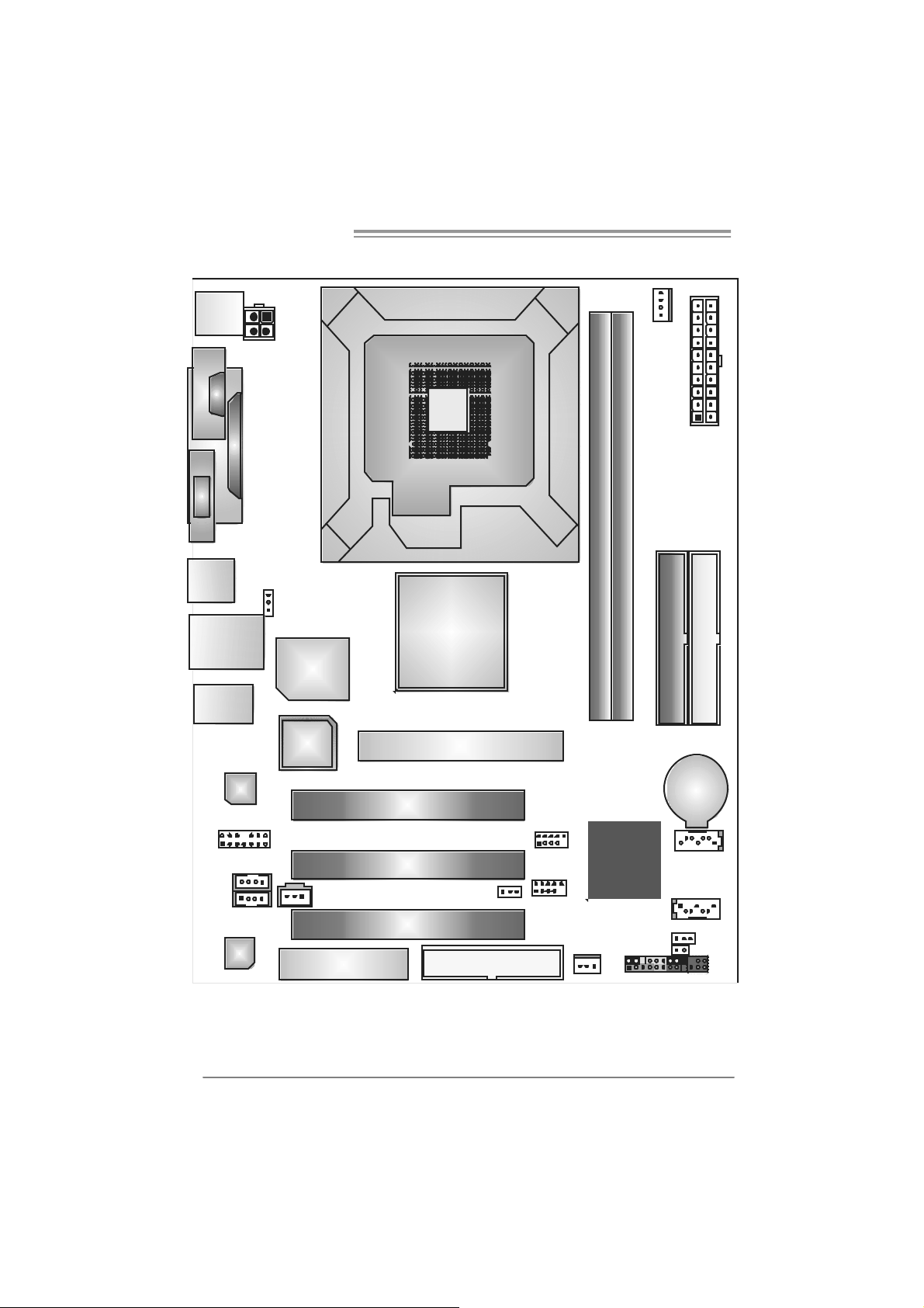
1.5 MOTHERBOARD LAYOUT
JKBMS1
J
C
O
M
1
JVGA1
JUSB1
JUSBLAN1
JAUDIO1
JATXPWR2
JPRNT1
J US BV1
Super
BIOS
I/O
LGA77 5
CPU1
P4M800 Pro
AGP1
JC FAN1
JATXPWR1
DIMM1
DIMM2
IDE1
IDE2
JCDIN 1
(opti onal)
6
JFAUDIO1
JAUX1
Codec
LAN
Note: represents the 1■
JSPDIFO1(Optional)
CNR1
PCI1
PCI2
PCI3
st
pin.
JUSBV2
FDD1
JU SB 2
JUSB3
VT8237R+
JSFAN1
JPAN EL1
BAT1
JSATA2
JSATA1
JCMOS1
JC I1
IR (optional)
(opt ional)
Page 7
P4M8 00Pro-D1
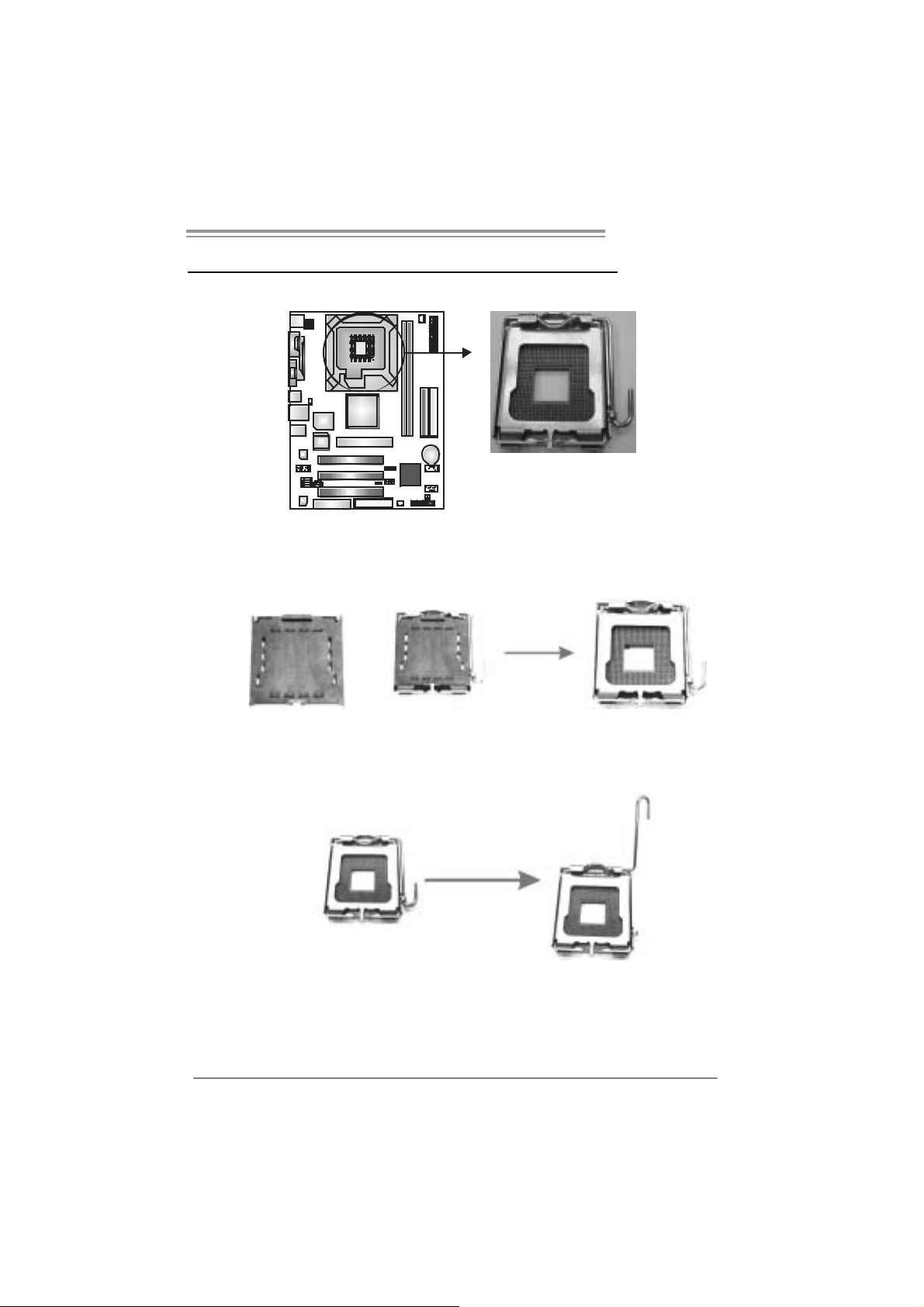
CHAPTER 2: HARDWARE INSTALLATION
2.1 INSTALLING CENTRAL PROCESSING UNIT (CPU)
Special Notice:
Remo v e Pin Cap before installation, and m ake good preserv ation
for future use. When the CPU is remov ed, cover the Pin Cap o n the
empty so cket to ensure pin legs won’ t be damag e d.
Pin Cap
Step 1: Pull the socket locking lever out from the socket and then raise
the lever up to a 90-degree angle.
7
Page 8
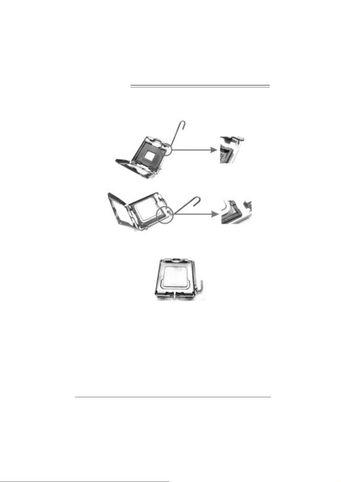
Motherboard Manual
Step 2: Look for the triangular cut edge on socket, and the golden dot on
CPU should point forwards this triangular cut edge. The CPU will
fit only in the correct ori entation.
Step 2-1:
Step 2-2:
Step 3: Hol d the CPU down firmly, and then lower the lever to locked
posi tion to com plete the installation.
Step 4: Put the CPU Fan and heatsink assembly on the CPU and buckle it
on the retenti on frame. Connect the CPU FAN power cable i nto
the JCFAN1. This completes the in stallati on.
8
Page 9
P4M8 00Pro-D1
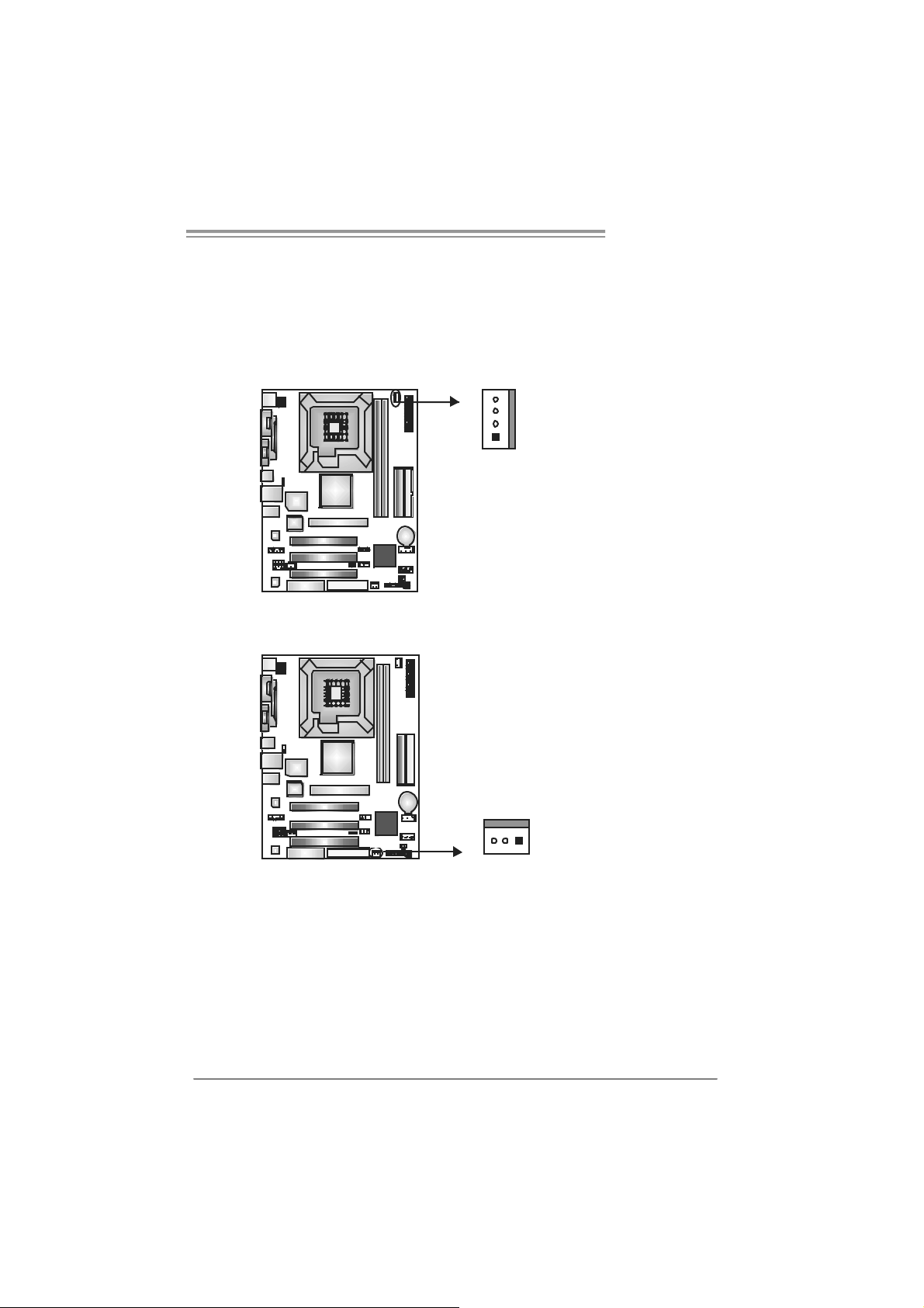
2.2 FAN HEADERS
These fan headers support cooling-fans built in the com puter. The fan
cable and connector may be different according to the fan manufacturer.
Connect the fan cable to the connector while matching the black wire to
pin#1.
JCFAN1: CPU Fan Header
4
1
JSF AN1 : Sy stem Fan H ead er
Pin
Assignment
1 Ground
2 +12V
3 FAN RPM rate
sense
4 Smart Fan
Control
Pin
Assignment
1 Ground
2 +12V
3 FAN RPM rate
sense
13
Note:
The JCFAN1 and JSFAN1 s upport 4-pin and 3-pin head connec tors. When c onnecti ng
with wires onto connectors, please note that t he red wire is t he positi v e and s hould be
connected to pi n#2, and the blac k wire is Ground and s hould be c onnected to GND.
9
Page 10

Motherboard Manual
2.3 INSTALLING SYSTEM MEMORY
A. Me mo ry Module s
DIMM2
DIMM1
1. Unlock a DIMM sl ot by pressing the retaini ng clips outward. Align a
DIMM on the slot such that the notch on the DIMM matches the
break on the Sl ot.
2. Insert the DIMM vertically and firmly into the slot until the retaining
chip snap back in place and the DIMM is properly seated.
B. Memory Capacity
10
DIMM Socket
Location
DIMM1 256MB/512MB/1GB
DIMM2 256MB/512MB/1GB
DDR Module
To t a l Me m o r y
Size
Max i s 2 G B.
Page 11
P4M8 00Pro-D1
2.4 CONNECTORS AND SLOTS
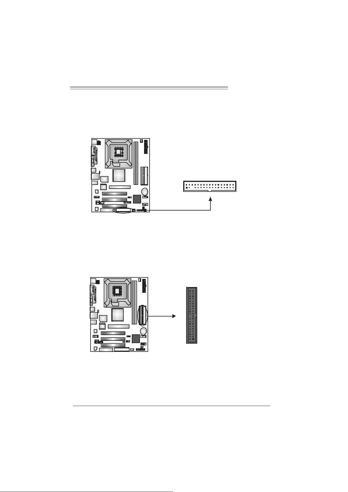
FDD1: Floppy Disk Connector
The motherboard provides a standard floppy disk c onnector that supports 360K,
720K, 1. 2M, 1.44M and 2. 88M f loppy disk types. This connector supports the
provided floppy drive ribbon cable.
IDE1 / IDE2: Har d Disk Connec to rs
The motherboard has a 32-bit Enhanced PCI IDE Controller that provides PIO
Mode 0~4, Bus Mast er, and Ult ra DMA 33/ 66/100/ 133 func t ionality . It has two
HDD connect ors - IDE1 (prim ary ) and I D E2 (s econdary).
The IDE connectors can connect a master and a s lave drive, so you can
connec t up to four hard disk drives. The first hard driv e s hould alway s be
connec t ed to IDE1.
2
1
3940
21
34
33
IDE2IDE1
11
Page 12

Motherboard Manual
A
PCI1 ~PC I3: Peripheral Componen t Interconne ct Slots
This mot herboard is equipped with 3 standard PCI slots. PCI st ands for
Peripheral Com ponent Int erconnect, and it is a bus standard for ex pansion
cards . This PCI s lot is designated as 32 bits.
AGP1: A ccele rat e d Graphi cs Port S l o t
Your m onit or will attach directly to that video c ard. This motherboard supports
video c ards for PCI slots, but it is also equipped with an Accelerat ed Graphics
Port (AGP). An AGP c ard will t ak e advantage of AGP tec hnology for improved
video efficiency and perf ormanc e, espec ially with 3D graphics .
PCI1
PCI2
PCI3
CNR1: Commun i cation Ne twork Ri se r Sl ot
The CNR specification is an open Indust ry St andard Arc hit ec t ure, and it defines
a hardware scalable riser card interf ac e, which supports modem only.
12
GP1
CNR1
Page 13

P4M8 00Pro-D1
CHAPTER 3: HEADERS & JUM PERS SETUP
3.1 HOW TO SET UP JUMPERS
The illustration shows how to set up jumpers. When the jumper cap is
placed on pins, the jumper is “close”, if not, that means the j umper i s
“open”.
Pin opened Pin closed Pin1-2 closed
3.2 DETAIL SETT INGS
JPANEL1: Front Panel Header
This 24-pin connector includes Power-on, Res et, HDD LED, Power LED, Sleep
butt on, speak er and IrDA (optional) Connect ion. I t allows user to connect the PC
case’ s front panel switch f un ctions.
PWR_LED
SLP
2
123
SPK
++
+
HLED
On/Of f
-
RST
24
I R (opt ional)
Pin Assignment Functio n P in Ass ignment Functio n
1 +5V 2 Sleep control
3 N/A 4 Ground
5 N/A 6 N/A N/A
7 Speaker
9 HDD LED (+) 10 Power LED (+)
11 HDD LED (-)
13 Ground 14 Power button
15 Reset control
17 N/A 18 N/A
19 N/A 20 Key
21 +5V 22 Ground
23 IRTX
Speaker
Connector
Hard drive LED
Reset button
IrDA Connector
(optional)
8 Powe r LE D (+)
12 Power LED (-)
16 Ground
24 IRRX
Sleep button
Powe r LED
Power-on button
IrDA Connector
(optional)
13
Page 14

Motherboard Manual
JAT XPW R1: ATX Powe r Source Conn e ctor
This connector allows user to connec t 20-pin power c onnector on t he ATX
power supply.
10 20
111
Pin Assignment Pin Ass ignment
1 +3.3V 11
2 +3.3V 12
3 Ground 13
4 +5V 14
5 Ground 15
6 +5V 16
7 Ground 17
8 PW_OK 18
9 Standby Voltage +5V 19
10 +12V 20
+3.3V
-12V
Ground
PS_ON
Ground
Ground
Ground
-5V
+5V
+5V
JAT XPW R2: ATX Powe r Source Conn e ctor
By c onnecting this connector, it will prov ide +12V to CPU power circ uit.
12
Pin
34
Assignment
1 +12V
2 +12V
3 Ground
4 Ground
14
Page 15

P4M8 00Pro-D1
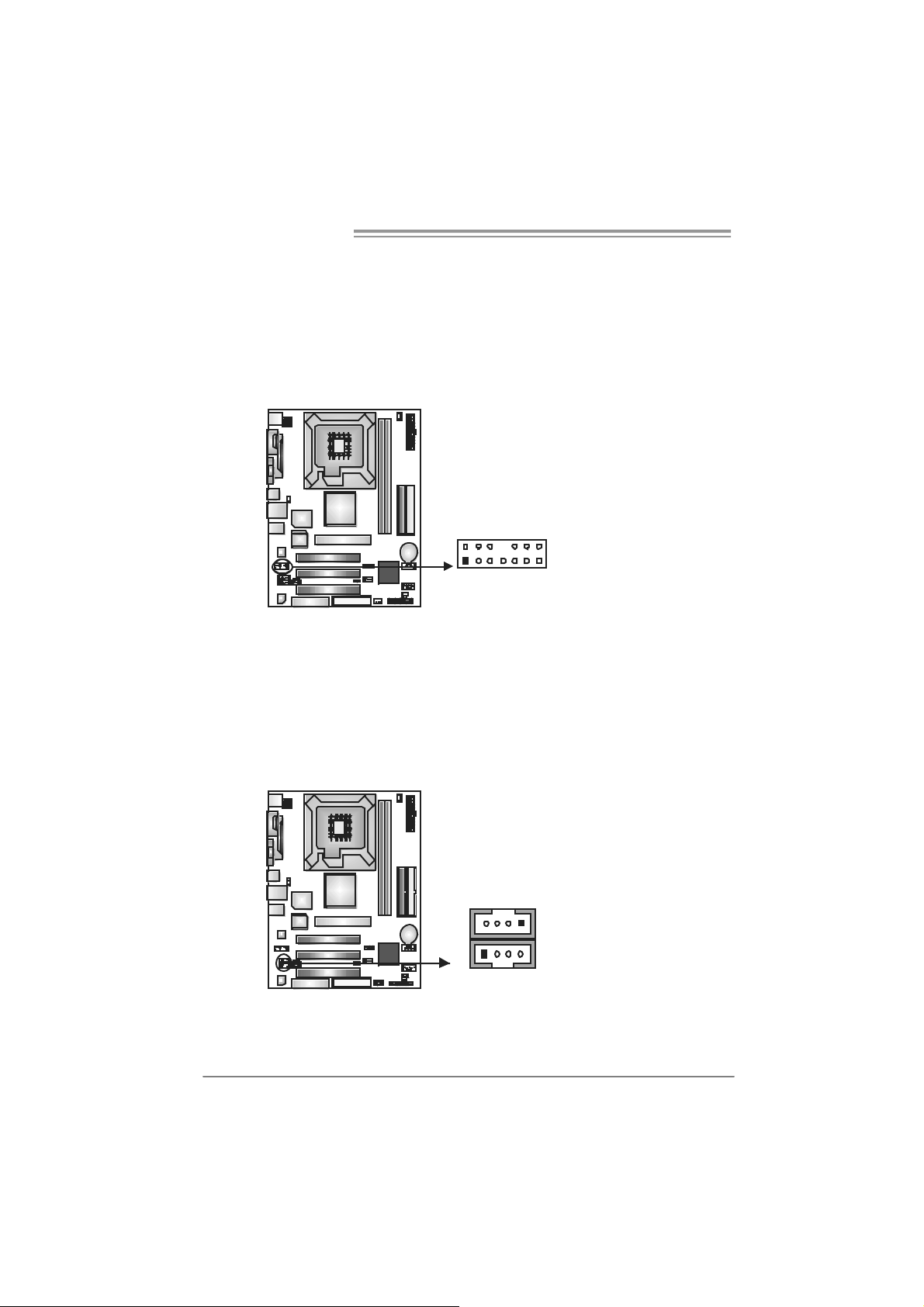
JUSB2/JUSB3: H ead er s for U SB 2. 0 Port s at F ront Pa n el
This header allows user to c onnect additional USB cable on the PC f ront panel,
and also can be c onnect ed with internal USB devic es, like U SB card reader.
Assignment
Pin
1 +5V (fused)
2 +5V (fused)
3 USB4 USB5 USB+
6 USB+
7 Ground
10
9
JUSB2
JUSB3
2
1
8 Ground
9 Key
10 NC
JUSBV1/JUSBV2: Powe r S ou rce Headers f or US B ports
Pin 1-2 C lose:
JU SBV1: +5V f or USB port s at JUSB1 and JUSBLAN 1.
JU SBV2: +5V f or USB port s at front panel (JU SB2/JU SB3).
Pin 2-3 C lose:
JU SBV1: USB ports at J U SB1 and J U SBLAN 1 are powered by +5V
standb y voltage.
JU SBV2: USB ports at f ront panel (JU SB2/JUSB3) are powered by +5V
standb y voltage.
3
31
1
3
1
3
1
JUSBV1
13
JUSBV2
Pin 1-2 close
1
Pin 2-3 close
3
Note:
In order to support this function “Power-On sy stem via USB device,” “JUSBV1/ JUSBV2”
jumper cap should be placed on Pin 2-3 indi v idually.
15
Page 16
Motherboard Manual
1
JFAUDIO1: Fron t Panel Audio Header
This header allows user to c onnect t he f ront audio out put cable wit h the PC front
panel. It will disable the out put on back panel audio c onnectors.
Pin Assignment
1 Mic-in/Stereo MIC-in
R
2 Ground
3 Stereo MIC-in L
4 Audio power
5 Right line-out/
Speaker-out Right
6 Right line-out/
Speaker-out Right
2
1
14
13
7 Reserved
8 Key
9 Left line-out/
Speaker-out Left
10 Left line-out/
Speaker-out Left
11 Right line-in (optional)
12 Right line-in (optional)
13 Left line-in (optional)
14 Left line-in (optional)
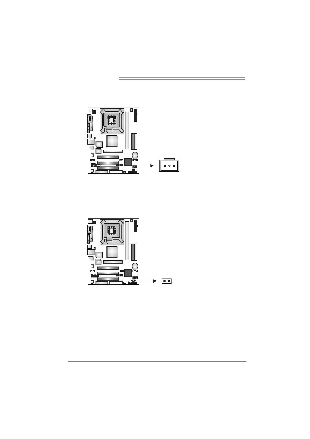
JCDIN1: CD-R OM A ud io-i n Connector
JAU X1: Aud io- i n Co n n ect or ( Opt i o na l)
This connector allows user t o connect the audio s ourc e from t he variaty dev ices,
like CD-R OM, DVD-ROM, PC I sound card, PCI TV turner card etc.
16
JCDIN1
14
14
JAUX
Assignment
Pin
1 Left Channel Input
2 Ground
3 Ground
4 Right Channel Input
Page 17

P4M8 00Pro-D1
JCMOS 1 : C l ea r CMO S Hea der
By plac ing the jumper on pin2-3, it allows us er to restore the BIOS s af e sett ing
and the CMOS dat a, please carefully f ollow the procedures to av oid damaging
the m otherboard.
13
Pin 1-2 Close:
Normal Operation (default).
Pin 2-3 Close:
Clear CMOS data.
31
1
3
※ Clear CMOS Proce dures:
1. R em ove AC power line.
2. Set the jumper to “Pin 2-3 close”.
3. Wai t for fi ve se co n ds.
4. Set the jumper to “Pin 1-2 close”.
5. Power on the AC.
6. R es et your des ired pas s word or c lear the C MOS data.
JSATA1 /JS ATA2: Serial ATA Connectors
The motherboard has a PCI t o SATA Controller wit h 2 channels SATA interf ace,
it satisfies the SATA 1.0 spec and with transfer rate of 1.5Gb/s.
Pin
Assignment
JSATA2
147
147
JSATA1
1 Ground
2 TX+
3 TX4 Ground
5 RX6 RX+
7 Ground
17
Page 18
Motherboard Manual
JSPDIFO1: Digi tal Au dio-out Connec tor (Optional)
This connector allows user to connec t the PCI bracket SPDIF output header.
JCI1: Chassis Open Head er (Optional)
This connector allows system to monit or PC cas e open stat us. If the signal has
been triggered, it will record to t he CMOS and s how t he message on next
boot-up.
Pin
Assignment
1 +5V
2 SPDIF_OUT
3 Ground
13
Pin
Assignment
1 Case open signal
2 Ground
18
12
Page 19
P4M8 00Pro-D1
CHAPTER 4: RAID FUNCTIONS
4.1 OPERATION SYSTEM
Supports Windows XP H om e/Prof essional Edition, and Windows 2000 Prof essi onal.
4.2 RAID ARRAYS
RAI D supports the f ollowing types of R AI D array s :
RAID 0: RAID 0 defines a disk striping scheme that improves disk read and write times for
RAID 1: RAID 1 defin es tech niques for mi rrori ng data.
many applications.
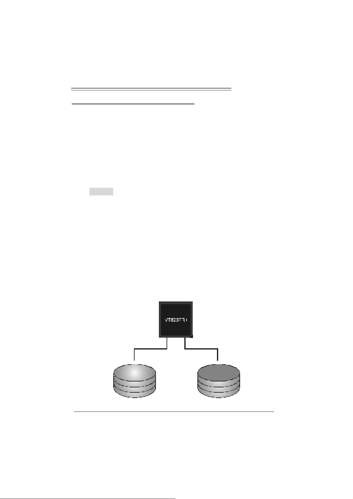
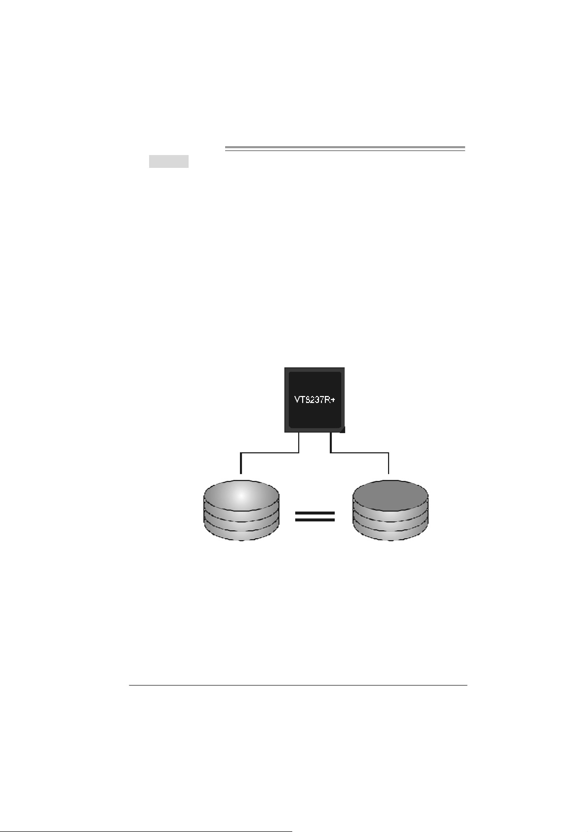
4.3 HOW RAID WORKS
RAID 0:
The controller “ stripes” data across multiple drives in a RAID 0 array system. It breaks
up a large file into smaller blocks and performs disk reads and writes across multiple
drives i n parallel. The size of each block is d etermined by the stripe size parameter,
which you set during the creation of the RAID set based on the system environment. This
technique reduces overall disk access time and offers high b andwidth.
Fea tures and Be nefits
Drives: Minim um 1, and m ax im um is up to 6 or 8. Depending on the
platform.
Uses: I ntended f or non-critical data requiring high dat a throughput, or any
environment that does not require fault toleranc e.
Benefits: provides inc reas ed dat a t hroughput, espec ially for large files. No
capac ity loss penalty f or parity.
Drawbacks: Does not deliver any f ault tolerance. If any drive in the array
fails, all data is lost.
Fault Tolerance: No.
Bl ock 1
Block 3
Block 5
Block 2
Block 4
Block 6
19
Page 20
Motherboard Manual
RAID 1:
Every read and write is actually carri ed out i n p aral lel across 2 disk drives in a RAID 1
array system. The mirrored (backup) copy of the data can reside on the same disk or on
a second redundant drive in the array. RAID 1 provides a hot-standby copy of data if
the active volume or d rive is corrupted or becomes unavailable because of a hardware
failure.
RAID techniques can be applied for high-availability solutions, or as a form of
automatic backup that eliminates tedious manual backups to more expensive and less
reliable media.
Fea tures and Be nefits
Drives: Minimum 2, and m ax im um is 2.
Uses: R AID 1 is ideal for small dat abas es or any other applicat ion t hat
requires f aul t tolerance and minimal ca paci t y.
Benefits: Prov ides 100% dat a redundancy. Should one driv e fail, t he
controller switche s to the other drive.
Drawbacks: R equires 2 driv es for the storage space of one driv e.
Performance is impaired during drive rebuilds.
Fa ult Tolerance: Yes.
20
Block 1
Block 2
Block 3
Block 1
Block 2
Block 3
Page 21
CHAPTER 5: USEFUL HELP
5.1 DRIVER INSTALLATION NOTE
After you installed your operating system, please insert the Fully Setup
Driver CD into your optical drive and install the driver for better system
perform ance.
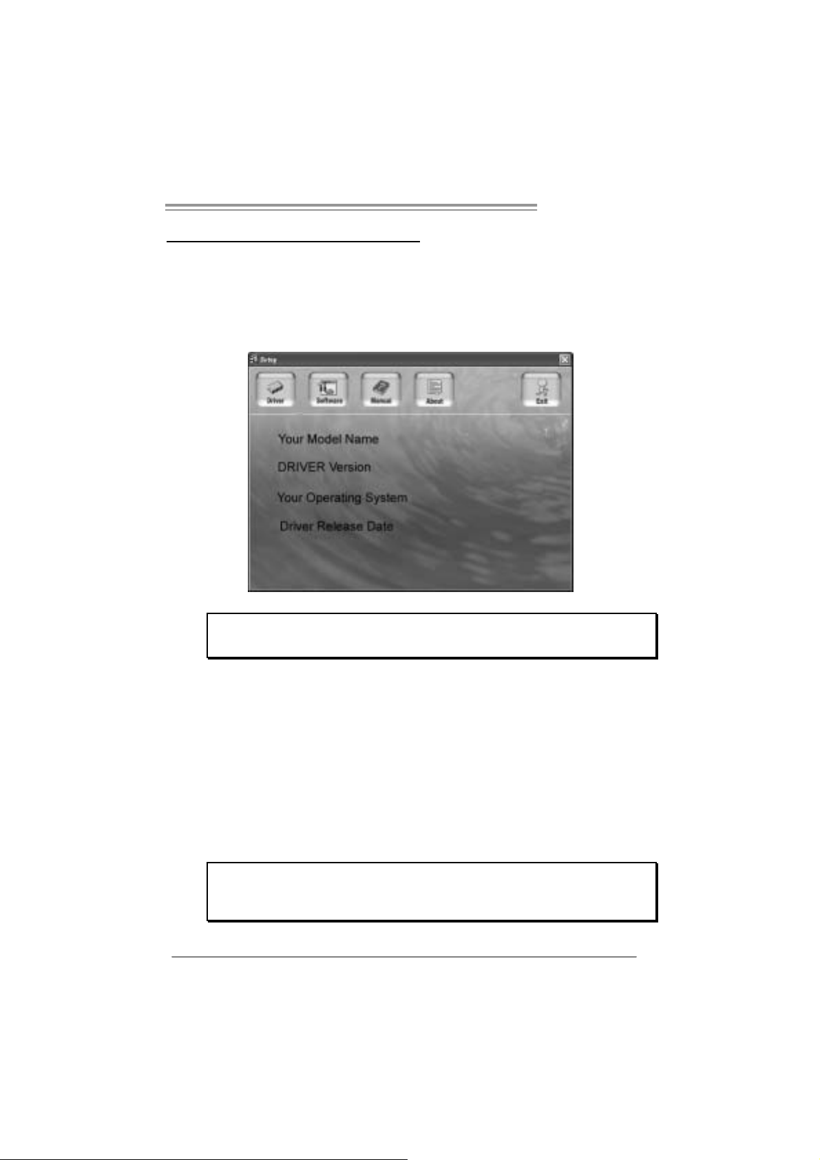
You will see the following window after you insert the CD
P4M8 00Pro-D1
The set up gu ide will auto detec t your mothe rboard and operating system.
Note:
If this window didn’t show up after y ou insert the Driver CD, please use file browser to
l ocate and execu t e th e fil e SET UP.EXE under yo ur o pti c al dr i ve.
A. Driver Installation
To install the driver, please click on the Driver icon. The setup guide wi ll
list the compatible driver for your motherboard and operating system.
Click on each device driver to launch the installation program.
B. Software Ins tallation
To install the software, please click on the Software icon. The setup guide
will list the software available for your system, click on each software title
to la unch th e insta l lat io n pr ogr a m.
C. Manual
Aside from the paperback manual, we also provi de manual in the Driver
CD. Click on the Manual icon to browse for available manual.
Note:
You will need Acroba t Re ad er to op en the man ual file. Please download the latest version
of Acrobat Reader software from
http://www.adobe.com/products/acrobat/readstep2.html
21
Page 22
Motherboard Manual
5.2 AWARD BIOS BEEP CODE
Beep Sound Meaning
One long beep f ollowed by t wo short
beeps
High-low siren sound CPU overheated
One Short beep when sy stem boot-up No error f ound during POST
Long beeps every ot her sec ond N o DRAM detect ed or ins t all
Video card not f ound or video c ard
mem ory bad
Sys t em will s hut down automatically
5.3 EXT RA INFORMATION
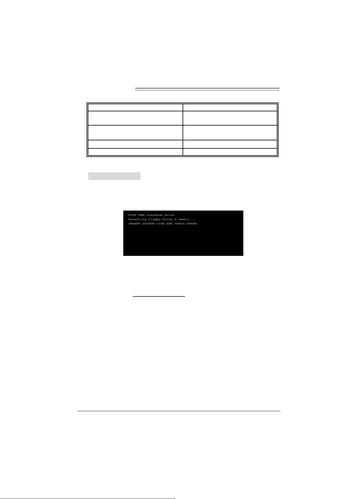
A. BIOS Update
After you fail to update BIOS or BIOS i s i n vaded by virus, the
Boot-Block function will help to restore BIOS. If the following message
is shown after boot-up the system, it means the BIOS contents are
corrupted.
In this Case, please follow the procedure below to restore the BIOS:
1. Mak e a bootable fl op py d isk .
2. Download the Flash Uti lity “AWDFLASH.exe” from the Biostar
website: www.bi o star.com.tw
3. Confi rm m otherboard model and download the respecti vely BIOS
fr om Bi os t ar w ebs ite.
4. Copy “AWDFLASH.exe” and respectively BIOS into floppy disk.
5. Insert the bootable disk into floppy drive and press Enter.
6. System will b oo t-up t o DOS p rompt.
7. Type “Awd flash xxxx.bf / sn/py/ r” in DOS prompt.
(xxxx means BIOS name.)
8. System will u pd ate BIOS a utoma ticall y an d re start.
9. The BIOS ha s bee n re covered an d will wo rk pro perl y.
22
Page 23

P4M8 00Pro-D1
B. CPU Overheated
If the system shutdown automatically after power on system for
seconds, that means the CPU protection function has been activated.
When the CPU is over heated, the motherboard will shutdown
automatically to avoid a damage of the CPU, and the system may not
power on again.
In this case, please double check:
1. The CPU cooler surface i s placed evenl y with the CPU surface.
2. CP U fan is rotated norm all y.
3. CPU fan speed is fulfilling with the CPU speed.
After confirmed, please follow steps below to relief the CPU protection
function.
1. Remove the power cord from power supply for seconds.
2. Wait for secon ds.
3. Plug in the power cord and boot up the system.
Or you can:
1. Clear the CMOS data.
(See “Close CMOS Header: JCMOS1” section)
2. Wait for secon ds.
3. Po we r on the syst em again.
23
Page 24

Motherboard Manual
e
5.4 TROUBLESHOOTING
Probable Solution
1. N o power to t he system at all
Power light don’t illuminate, f an
inside power supply does not t urn
on.
2. I ndic at or light on k ey board does
not t urn on.
Sys t em inoperativ e. Key board lights
are on, power indicator lights are lit,
and hard driv e is spinning.
Sys t em does not boot from hard dis k
drive, c an be booted from opt ic al drive.
Sys t em only boots from optic al drive.
Hard disk can be read and applic ations
can be used but booting f rom hard disk
is imposs ible.
Screen m essage says “Invalid
Conf igurat ion” or “CMOS F ailure.”
Cannot boot sy s t em after installing
sec ond hard drive.
1. Make s ure power c able is
sec urely plugged in.
2. Replace cable.
3. Contact technical support.
Us ing even press ure on both ends of
the DIMM, press down f irm ly until the
module s naps into place.
1. C hec k cable running from disk to
disk controller board. Make s ure
both ends are securely plugged
i n; check th e driv e ty p e in t h e
standard CMOS setup.
2. Bac k ing up t he hard drive is
ext rem ely import ant. All hard
disk s are capable of break ing
down at any t ime.
1. Bac k up dat a and applicat ions
files.
2. R eform at the hard drive.
Re-ins t all applications and dat a
using backup disks.
Rev iew syst em’s equipment . Make sur
correc t inf ormat ion is in set up.
1. Set m as t er/s lave jumpers
correctly.
2. R un SETUP program and select
correc t drive ty pes. Call the drive
manufacturers for compatibilit y
with other drives.
24
Page 25

P4M8 00Pro-D1
This page is intenti onally left blank
25
Page 26

Motherboard Manual
g /
APPENDENCIES: SPEC IN OTHER LANGUAGE
GERMAN
Spezifikationen
LGA 77 5
CPU
FS B 400 / 53 3 / 8 00 / 1066 MHz
Chipsatz
Grafik Integrierter UniC hrome Pro Chipsatz Max. 64MB gem einsam ben utz ter Videos peicher
Super E/A
Arbeitsspeic
her
IDE Integrierter IDE-Controller
SATA Integrierter Serial ATA-Controller
LAN PHY Realtek RTL8201CL
Audio-Code
c
Steckplätz e
schluss
Intel Core2Duo / Pentium 4 /
Pentium D / Celeron D Prozessoren
mit bis zu 3,8 GHz
VIA P4M800 PRO
VIA VT8237R+
ITE I T 87 05
Biet et die h äufig verwe ndete n alte n
Super E/A-Funktione n.
Low Pi n C ount-S c hnit tst elle
DDR DIMM-Stec kplätze x 2
Unterstützt DDR 400 / 333
Jeder DIMM unterstützt
256/512MB /1GB DDR.
Max. 2GB Arbeitsspeicher
AL C655 / AL C65 8
AGP-Steckplatz x1
CNR-Steckplat z x1
PCI-Steckplatz x3
Diskettenlaufwerkanschluss x1 Jeder Anschluss unterstützt 2 DiskettenlaufwerkeOnboard-A n
IDE-Anschluss x2 Jeder Anschluss unterstützt 2 IDE-Laufwerke
Unterstützt Hyper -Threadi n
/ Enhanced Intel SpeedStep® / Extended
Memory 64 Technology
Umgebungskontrolle,
Hardware-Überwachung
Lüfterdre hzahl-Controller
"Smart Guar dian" -Funktion v on ITE
Ein-Kanal D DR S pei cherm o dul
registrierte DIMMs. ECC DIMMs werden nicht
unters tütz t.
Unterstützt PIO-Modus 0~4,
Ultra DMA 33 / 66 / 100 / 133Bus Master-Modus
Konform mit der SATA-Spezifikation Version 1.0.
Datentrans ferr ate bi s zu 1.5 Gb/s
10 / 1 00 Mb/s A uto-Neg otiation
Halb-/ Vollduplex-Funktion
6-Kanal-Au dioaus gabe
AC ’97 Ver sion 2.3
Execute Dis a ble Bit
26
Page 27

Rückseiten-
E/A
Platinengrö
ße.
Sonderf unkt
ionen
OS-Unterst
ützung
P4M8 00Pro-D1
Spezifikationen
SATA-Anschluss x2 Jeder Anschluss unterstützt 1 SATA-Laufwerk
Fronttafelanschluss x1 Unterstützt die Fronttafelfunktionen
Front-Audioa nschluss x1
CD-IN-Anschluss x1 Unterstützt die CD Audio-I n-Funktion
S/PDIF-Ausgangsanschluss x1
(optional)
CPU-Lüfter-Sockel x1
System-Lüfter-Sockel x1 System-Lüfter-Stromversorgungsanschluss
"Gehä use o ffe n"-Soc kel x1
(optional)
"CMOS löschen"-Sockel x1
USB-Anschluss x2 Jeder A nschluss unterstützt 2
Stromanschluss (20-polig) x1
Stromanschluss (4-polig) x1
PS/2-Tas tatur x1
PS/2-Maus x1
Serieller Anschluss x1
Druckeranschluss x1
VGA-Anschluss x1
LAN-Anschluss x1
USB-Anschluss x4
Audioanschluss x3
201 mm (B) X 244 mm (L)
Unterstützt RAID 0 / 1
Windows 2K / XP
Unterstützt die
Fronttafel-Audioanschlussfunktion
Unterstützt die digitale Audioausgabefunktion
CPU-Lüfterstromversorgungsanschluss (mit
Smart Fan-Funktion)
Zur Erkennung ein es geö ffneten Ge häus es
Fronttafel-USB-Anschlüsse
Biostar behält sich das Recht vor, ohne
Ankündigung die Unterstützung für ein
Betriebss ys tem hinzuzufü gen od er zu entf erne n.
27
Page 28

Motherboard Manual
/
p
/
q
FRANCE
LGA 77 5
UC
Bus frontal 400 / 53 3 / 8 00 / 1066 MHz
Chipset
Graphi ques Integré dans l a chipset U niChrome
Super E/S
Mémoire
principale
IDE C ontrôleur IDE int égr é
SATA Contrôleur Serial ATA intégré :
LAN PHY Realtek RTL8201CL
Codec
audio
Connecteu
r
embarqué
Processeurs Intel Core 2Duo / Pentium
4 / Pentium D / Celer on D jusqu'à 3,8
GHz
VIA P4M800 PRO
VIA VT8237R+
Pro
ITE I T 87 05
Four nit la fo nctionnalité de Su
patrimoniales la plus utilisée.
Interface à faible compte de broches
Fent es DDR DIMM x 2
Prend en c harge la DDR 400 / 333
Chaque DIMM pren d en ch arge des
DDR de 256 Mo /512 Mo / 1Go
Capacité mémoire maximale de 2 Go
AL C655 / AL C65 8
Fente AGP x1
Fente CNR x1 Fentes
Fente PCI x3
Connec teur de di squette x1
Connecteur IDE x2
Connecteur SA TA x2
er E/S
S PEC
Prend en charge les technologies
Hyper -Thre adin g / d'exécution de bit de
désactivation / I ntel SpeedStep® optimisée
mémoire étendue 64
Mémoire vidéo partagée maximale de 64 Mo
Initiatives de contrôle environnementales,
Moniteur de m atéri el
Contrôleur de vitesse de vent ilat eur
Fonction "Gardien i ntelligent" de l'ITE
Module de mémoire DDR à mode à simple voie
Les DIMM à r egistres et DIMM avec code
correcteurs d'erreurs sont pas prises en charge
Prend en charge le mode PIO 0~4,
Mode pri nc ipale d e Bus Ultra DM A 33 / 66 / 10 0
133
Conforme à la spécification SATA Version 1.0
Taux de transfert jusqu'à 1.5 Go/s.
10 / 100 Mb/s négociation automatique
Half / Full duplex capability
Sortie audio à 6 voies
AC ’97 Ver sion 2.3
ue c on nec tor prend en charge 2 lec teurs de
Cha
disquettes
Chaque con necteur prend e n char ge 2
péri phéri ques I DE
Chaque con necteur prend e n char ge 1
périphérique SATA
de
28
Page 29

q
E/S du
pann eau
arrière
Dim ension
s de la
carte
Fonc tionna
lités
spéciales
Suppor t
SE
P4M8 00Pro-D1
S PEC
Connecteur du pa nneau avant x1
Connecteur Audio du p anneau
avantx1 x1
Connecteur d'entré e CD x1 Prend en ch arge l a fonction d'entrée au dio d e CD
Connecteur de sortie S/PDIF x1
(en option)
Embase de ve ntilat eur UC x1
Embase d e ve ntilateur système x1 Alimentation électrique du ventilateur système
Embase d' ouvertur e de châssis x1
(en option)
Embas e d'e ffacement CM OS x1
Connecteur USB x2
Connecteur d'alimentation x1
(20 broches)
Connecteur d'alimentation x1
(4 broches)
Clavier PS/2 x1
Souris PS/2 x1
Port série x1
Port d'i mprimante x1
Port VGA x1
Port LAN x1
Port USB x4
Fiche audio x3
201 mm (l) X 244 mm (H)
Prise en c harge RAID 0 / 1
Windows 2K / XP
Prend en charge les équipements du panneau
avant
Prend en charge la fonct ion a udio du p ann eau
avant
Prend en c harge la fonct ion de s ort ie audio
numérique
Alimentation électrique du ventilateur UC (avec
fonction de ventilateur intelligent)
Pour la fo ncti on de détect ion d'intrus dans le
châssis
ue c on nec teur prend en charge 2 ports USB
Cha
de panneau avant
Biostar se réserve le droit d'ajouter ou de
supprimer le support d e SE av ec ou sans préavis.
29
Page 30

Motherboard Manual
ITALIAN
SPECIFICA
LGA 77 5
CPU
FS B 400 / 53 3 / 8 00 / 1066 MHz
Chipset
Grafica Integrata nel Chi pset UniC hrome Pr o La memoria vi deo condivisa massima è di 64MB
Super I/O
Memoria
principale
IDE Controller IDE integrato
SATA Controller Serial ATA integrato
LAN PHY Realtek RTL8201CL
Codec
audio
Connett ori
su scheda
Processore Intel Core2Duo / Pentium
4 / Pentium D / Cel ero n D fino a 3.8
GHz
VIA P4M800 PRO
VIA VT8237R+
ITE I T 87 05
Fornisce le funzionalità legacy Super
I/O us ate pi ù comu nement e.
Interfaccia LPC (Low Pin Count)
Al loggi DIMM DDR x 2
Support o di DDR 400 / 333
Ciascun DIMM su pporta DDR 256MB
/512MB / 1GB
Capacità massima della memoria 2GB
AL C655 / AL C65 8
Alloggio AGP x1
Alloggio CNR x1 Alloggi
Alloggio PCI x3
Connett ore flo ppy x1 C iasc un c onn et tore s up porta 2 unità Flopp y
Connett ore IDE x2 Ciascun c onnett ore support a 2 unit à IDE
Connett ore SA TA x2 Cias cun c onn et tore s up porta 1 uni tà SA TA
Suppor to di Hyper -T hreadi ng / Execute Disable
Bit / Enhanced Intel SpeedStep® / Tecnologia
Extende d Mem or y 64
Funzioni di controllo dell’ambiente:
Monitoraggio hardware
Controller velocità ventolina
Funz ione "Smar t Guardi an" di I TE
Modulo di memoria DDR a canale singol o
DIMM registrati e DIMM ECC non sono supportati
Suppor to modalità PIO Mode 0-4
Modali tà Bus Master Ul tra DMA 33 / 66 / 100 /
133
Compatibile specifiche SATA Versione 1.0.
Veloc ità di t rasferiment o dei dat i fi no a 1. 5 G b/s .
Negozi azione automati ca 10 / 100 Mb /s
Capacità Half / Full Duplex
Uscita audio 6 canali
AC ’97 Ver sione 2. 3
30
Page 31

I/O
pannello
posteriore
Dim ension
i scheda
Caratterist
iche
speciali
Sistemi
operativi
supportati
P4M8 00Pro-D1
SPECIFICA
Connettore pannello frontale x1 Supporta i servizi del pannello fr ontale
Connettore audio frontale x1 Supporta la funzione audi o pannello frontale
Connett ore CD-in x1 Supporta la fu nzione i nput audio C D
Connettore outp ut SPDIF x1
(optional)
Collettore ventolina CPU x1
Collettore ventolina sistema x1 Alimentazione ventolina di sistema
Collettore apertura telaio x1
(optional)
Collettore cancellazione CMOS x1
Connett ore USB x2
Connettore alimentazione x1
(20 pin)
Connettore alimentazione x1
(4 pin)
Ta s t i era P S /2 x 1
Mouse PS/2 x1
Porta seriale x1
Porta s tampante x1
Porta VGA x1
Porta LAN x1
Porta USB x4
Connett ore au dio x3
20 1 m m (largh ez za) x 244 mm
(altezza)
Suppor to RAID 0 / 1
Windows 2K / XP
Suppor ta la fu nzi one d’outp ut a udio digi tale
Alimentazione ventolin a CPU (c on f unz io ne S m art
Fan)
Per la funzione di rilevame nto i ntrusione telaio
Ciascun connettore supporta 2 porte USB
pannello frontale
Biostar si riserva il diritto di aggiungere o
rimuovere il supporto di qualsiasi sistema
operativo senza pre avviso.
31
Page 32

Motherboard Manual
g
SPANISH
Especificación
LGA 77 5
CPU
FS B 400 / 53 3 / 8 00 / 1066 MHz
Conjunto
de chips
Gráfi cos
Súper E/S
Memoria
principal
IDE Controlador IDE inte grado
SATA Controlador ATA Serie Integrado
Red Local Realtek RTL8201CL
Códecs de
sonido
Conectore
s en placa
Procesador I ntel Core 2Duo / Penti um
4 / Pentium D / Celero n D hasta 3, 8
GHz
VIA P4M800 PRO
VIA VT8237R+
Integrados en el conjunto d e chips
UniChrom e Pro
ITE I T 87 05
Le ofrece las funcionalidades
hereda das de uso más común Súper
E/S.
Interfaz de cuenta Low Pin
Ranuras DIMM DDR x 2
Admite DDR de 400 / 333
Cada DIMM admite DDR de 25 6MB /
512MB / 1GB
Capacidad máxima de memoria de
2GB
AL C655 / AL C65 8
Ranura A GP X1
Ranura CNR X1 R anuras
Ranura PC I X3
Conector disco flexible X1
Admite Hyper-Threading / Bit de deshabilitación
de e jec ución / I ntel Spee dStep® Mejorad o /
Tec nología Extended M emory 64
Memoria máxima de ví deo compartida de 64MB
Iniciativas de control de entor no,
Monitor hardware
Cont rolador de veloc idad de ve ntilador
Función "Guardia inteligente" de ITE
Módulo de memoria DDR de canal Sencillo
No admite DIMM re
con ECC
Soporte los Mo dos PIO 0~4,
Modo b us maest ro Ultra DMA 33 / 66 / 100 / 133
Compatible con la versión SATA 1.0.
Tasas de transferencia de hasta 1.5 Gb/s.
Negoci ac ión de 10 / 100 M b/s
Funciones Half / Full dúplex
Salida de sonido de 6 canales
AC ’97 Vers ión 2.3
Cada con ector s oport a 2 uni dades de di sco
flexible
istrados o DIMM compatibles
32
Page 33

Panel
trasero de
E/S
Ta m añ o de
la placa
Func iones
especiales
Soporte de
sistema
operativo
P4M8 00Pro-D1
Especificación
Conector IDE X2 Cada conector soporta 2 dispositivos IDE
Conector SATA X2 Cada conector soporta 1 dispositivos SATA
Conector de panel frontal X1 Soporta instalaciones en el panel frontal
Conector de s onido front al X1 Soport a func io nes de sonid o en el pa nel fr ontal
Conector de entra da de C D X1 Soporta funció n de e ntrada de sonido de C D
Conector de salida S/PDIF X1
(opcional)
Cabecer a d e ve ntil ador de C PU X 1 Fuent e de alime ntac ión de ve ntilador de C PU (con
Cabecer a d e ve ntil ador de
sistema X1
Cabecera de chasis abi erto X1
(opcional)
Cabecer a d e b orr ado de CMO S X1
Conector USB X2 Cada conector soporta 2 puertos USB fro ntales
Conector de alimentación X1
(20 patillas)
Conector de alimentación X1
(4 patillas)
Te c l a d o P S /2 X 1
Ratón PS/2 X1
Puerto s erie X1
Puert o de impr esora X1
Puerto VGA X1
Puert o de red loc al X1
Puerto US B X4
Conector de sonido X3
201mm. (A) X 244 Mm. (H)
Admite RAID 0 / 1
Windows 2K / XP
Soporta funció n de salida de sonido di gital
funció n Smart Fan )
Fuente de alimentación de ventilador de sistema
Función de detec ción de i ntrusos e n el chas is
Biostar s e reserva el derecho de añadir o r etirar el
soporte de cualquier SO con o sin aviso previo.
33
Page 34

Motherboard Manual
/
p
g
ç
PORTUGUESE
ESPECIFICAÇÕES
LGA 77 5
CPU
FS B 400 / 53 3 / 8 00 / 1066 MHz
Chipset
Placa
gráfica
Especificaç
ão Sup er
I/O
Memória
principal
IDE Controlador IDE inte grado
SATA Controlador Serial ATA integrado
LAN PHY Realtek RTL8201CL
Codec de
som
Conectore
s na placa
34
Processador Intel Core 2Duo / Pentium
4 / Pentium D / Cel eron D até 3,8 GHz
VIA P4M800 PRO
VIA VT8237R+
Integrada no chipset U niChrome Pro M emória de víde o máxi ma partilha da: 64 MB
ITE I T 87 05
Proporciona as fu ncionalidades mais
utilizadas em termos da es
Super I/O.
Int erface LPC (Low Pi n Co unt).
Ranhuras DIM M D DR x 2
Suport a mó dulos DDR 40 0 / 3 33
Cada mó dulo DIMM suporta uma
memória DDR de 256MB /512 MB / 1
GB
Capacidade máxima de memória : 2
GB
AL C655 / AL C65 8
Ranhura AGP x1
Ranhura CNR x1 Ranhur as
Ranhura PCI x3
Conector da unidade de
disquetes x1
Conector IDE x2 Cada conector suporta 2 dispositivos IDE
Conector SATA x2 Cada conector suporta 1 dispositivo SATA
ecificação
Suporta as tec nologias Hyper-T hrea ding /
Execute Dis able Bit
/ Exte nded Memory 64
Iniciativas para controlo do am biente
Monitorização do hardware
Cont rolador da veloc idade da v entoin ha
Função "Smart G uardia n" da I TE
Módul o de memória DDR de canal s im ples
Os módulos DIMM re
são suportados
Suport a o mod o PIO 0~4,
Modo Bus m as ter Ultra DM A 33 / 66 / 10 0 / 1 33
Compatibilidade com a especifica
1.0.
Velocidades de transmissão de dados até 1.5
Gb/s .
Auto negociaç ão de 10 / 100 MB/s
Capacidade semi/full-duplex
Saída de áudio de 6 canais
AC ’97 Ver são 2. 3
Cada conector suporta 2 unidades de disquetes
En hanc ed I nte l SpeedStep®
istados e os DIMM ECC não
ão SATA versão
Page 35

ç
Entradas/
p
Saídas no
painel
traseiro
Ta m a n h o
da pl aca
Característ
icas
especiais
Sistemas
operativos
suportado
s
P4M8 00Pro-D1
ESPECIFICAÇÕES
Conector do pai nel fro ntal x1 Para s uporte de várias funç ões no painel fro ntal
Conector de áudi o fro ntal x1 Suporta a função de áudio no painel fr ontal
Conector para e ntrada de C Ds x1 Suporta a e ntrada de áudi o a part ir de C Ds
Conector de saída S/PDIF x1
(opcional)
Conector da ve ntoi nh a d a C PU x1
Conector da ve ntoi nh a d o
sistema x1
Conector para detecç ão da
abertura do chassis(opcional) x1
Conector para limpez a do CMOS x1
Conector USB x2
Conector de alimentação x1
(20 pin os)
Conector de alimentação x1
(4 pinos)
Te c l a d o P S /2 x 1
Rato PS/2 x1
Porta série x1
Porta para impressora x1
Porta VGA x1
Porta LAN x1
Porta USB x4
Tomada de áu dio x3
201 mm (L) X 244 mm (A)
Suporta as funções RAID 0 / 1
Windows 2K / XP
Supor ta a saí da de áu dio di git al
Alimenta
Smart Fan)
Alimentação da ventoi nha do sistema
Para detectar qualquer intrusão no chassis
Cada con ector s uport a 2 port as USB no pai nel
frontal
A Biostar reserva-se o direito de adicionar ou
remover su
com ou sem aviso prévio.
ão da vent oi nha da CPU (com a função
orte par a qualquer sistema operativo
35
Page 36

Motherboard Manual
/
POLISH
SPEC
LGA 77 5
Procesor
FS B 400 / 53 3 / 8 00 / 1066 MHz
Chipset
Grafika
Pamięć
główna
Super I/O
IDE Z int egr owany kont roler ID E
SATA Zintegrowany kontroler Serial ATA
LAN PHY Realtek RTL8201CL
Kodek
dźwiękowy
Złącza
wbudowan
e
Proc esor Intel C or e2D uo / Pe ntium 4
Pentium D / Celeron D do 3,8 GHz
VIA P4M800 PRO
VIA VT8237R+
Zintegrowana w chipsecie UniChrome
Pro
Gniaz da DDR DIM M x 2
Obsługa D DR 400 / 333
Każde gniazd o DIMM obsługuje
moduły 25 6MB /512MB / 1GB DDR
Maks. wielkość pamięci 2GB
ITE I T 87 05
Zapewnia najbardz iej pows zechne
funkc je S uper I/O .
Interfejs Low Pin Count
AL C655 / AL C65 8
Gniazdo AGP x1
Gniazdo CNR x1 Gniazda
Gniazdo PCI x3
Złącze napędu dyskietek x1 Każde z łącze obsługuje 2 na pędy dys kietek
Złącze IDE x2 Każde z łącze obsługuje 2 urz ądze nia I DE
Złącze SATA x2 Każde złącze obsług uje 1 urządzenie SATA
Złącze panela prz ed niego x1 Obsługa eleme ntów pa nela przed niego
36
Obsługa Hyper-Threading / Execute Disable Bit /
Enha nced Int el SpeedStep® / Exten ded Memory
64 Tec h nology
Maks. wielkość współdzielonej pamięci video
wynosi 64MB
Moduł pamięci DDR z trybem pojedynczego
kanału
Brak obsługi Registered DIMM oraz ECC DIMM
Funkcje kontrol i warunków prac y,
Monitor H/W
Kontroler prędkości wentylatora
Funkcja ITE "Smart Guar dian"
obsługa PIO tryb 0~4,
Ultra DMA 33 / 66 / 100 / 133 Tryb Bus Master
Zgodność ze specyfikacją SATA w wersji 1.0.
Transfer danych do 1.5 Gb/s.
10 / 100 Mb/s z automatyczną neg ocjac ją
szybkości
Działanie w trybie połowic znego / pełnego
dupleksu
6 ka nałowe wyjście audio
AC ’97 w w ersji 2.3
Page 37

Back Panel
I/O
Wymiary
płyty
Funkcje
specjalne
Obsluga
systemu
operacyjn
ego
P4M8 00Pro-D1
SPEC
Przednie złącze audio x1 Obsługa funkcji audi o na panelu przed nim
Złącze wejścia CD x1 Obsługa funkcji wejścia audio CD
Złącze wyjścia S/PDIF(opcja) x1 Obsługa f unkc ji cyfrow e go w y jśc ia audi o
Złącze główkowe wentylatora
procesora x1
Złącze główkowe wentylatora
systemowego x1
Złącze główkowe ot warcia
obudow y(opcja) x1
Złącze główkowe kasowani a
CMOS x1
Złącze USB x2
Złącze zas ilania (2 0 pi now e) x1
Złącz e zas ilania (4 pinowe) x1
Klawiatura PS/2 x1
Mysz PS/2 x1
Port szeregowy x1
Port druk arki x1
Port VGA x1
Port LAN x1
Port USB x4
Gniazdo audio x3
201 mm (S) X 244 m m (W)
Obsługa RAID 0 / 1
Windows 2K / XP
Zasi lanie w entylatora procesora (z funkcją Smart
Fan)
Zasilanie wentylatora s ystemowego
Do funkcji wykrywani a naruszenia obudowy
Każde złącze obsług uje 2 porty US B na pa nelu
prz ednim
Bi ostar zas trzega sobie prawo dodawania lu b
odwoływania obsługi dowolnego systemu
operacyjnego bez powiadomie nia.
37
Page 38

Motherboard Manual
/
р
RUSSIAN
CPU
(централь
ны й
проц ес сор
)
FS B 400 / 53 3 / 8 00 / 1066 МГц
Набор
микросхе
м
Графика
Основная
память
Super I/O
IDE
SATA
Локальна
я сеть
Звуковой
кодек
Встроенн
ый разъём
LGA 77 5
Процессор Intel Core2Duo / Pentium
4 / Pentium D / Celeron D до 3. 8 ГГц
VIA P4M800 PRO
VIA VT8237R+
Встроенная в набо р м икросхем
UniChrom e Pro
Слоты DDR DIMM x 2
Подде рж ка DDR 40 0 / 3 33
Каждый модуль DIMM
поддержива ет 256MB / 5 12МБ / 1ГБ
DDR
Максимальная ёмк ость памя ти 2 ГБ
ITE I T 87 05
Обес печива ет на ибо лее
использ уемы е дейс твующи е
функциональные возможности
Super I/O.
Интерф ейс с низким количеством
выводов
Вс троенное устройств о управления
вс трое нны м и ин терфе йс ам и
устройств
Вс троенное посл едов ательное
устройство управле ния ATA
Realtek RTL8201CL
AL C655 / AL C65 8
Слот AGP x1
Слот CNR x1 Слоты
Слот PCI x3
Разъём НГМД x1
Разъём IDE x2
СПЕЦ.
Подде рж ка техн оло гий Hyper-Threading /
Execute Dis able Bit
/ Ext e nded Mem ory 64 Technol ogy
Максимальная совместно использ уемая видео
память составляет 64 МБ
Модуль памяти с одн ок а наль ным реж имом DDR
Не поддерживае т зарегистриров анные модули
DIMM and ECC DIMM
Иниц иа ти вы по охране ок ружающей среды,
Аппара тны й монитор
Регуля тор скор ос ти
Функция IT E "Smart Guardian"
(Интелле ктуа льна я защита)
Режим "хозя ина" шины Ultra DMA 33 / 66 / 100
/ 1 33
Подде рж ка режима PIO 0~4,
скорос ть передач и дан ных до 1. 5 ги габ ит/с.
Соотве тс тв ие с пец ифик ац и и SATA верси я 1. 0.
Автоматическое согласование 10 / 100 Мб/с
Частичная / пол ная дуп лекс на я способн ость
Шестика нальный зву ковой выход
AC ’97 Версия 2.3
Каждый
гибк их магнитных дисках
Каждый разъём подде рж ивае т 2 вс т рое нных
инт ерф ейса накопителе й
азъём п оддерживае т 2 нако пи тел я на
En hanc ed I nte l SpeedStep®
38
Page 39

Задн яя
пане ль
средств
ввода-выв
ода
Размер
пане ли
Специаль
ны е
техн ическ
ие
характер и
стики
Подде рж к
а OS
P4M8 00Pro-D1
СПЕЦ.
Разъём SATA x2
Разъём на лицево й пане ли x1 Поддержка устро йств на лицево й па нел и
Входно й з вук овой раз ъём x1
Разъём вв ода дл я CD x1 Подде ржка функции вво да для CD
Разъём выво да для S/PDIF x1
(допо лнитель но )
Контактирующее п рис посо бле ние
вентилятора центрального
процессора x1
Контактирующее п рис посо бле ние
вентилятора системы x1
Шасси открытого контактирующего
прис пособл ени я x1
(допо лнитель но )
Открытое контак тирующее
прис пособл ени е CMOS x1
USB-разъём x2
Разъем пит ан ия (20 вывод ) x1
Разъем пит ан ия (4 вывод) x1
Клавиатура PS/2 x1
Мышь PS/2 x1
Последо вате льны й по рт x1
Порт подключения пр инт ера x1
Порт VGA x1
Порт LAN x1
USB-порт x4
Гнездо для по дключ ения
наушников x3
201 мм (Ш ) X 244 мм (В)
Подде рж ка RAID 0 / 1
Windows 2K / XP
Каждый разъём подде рж ивае т 1 устро йство
SATA
Подде рж ка звук овых функций на лиц ево й
пане ли
Подде рж ка выво да циф ровой звуко вой
функции
Источн ик пи та ния для ве нтилятора
ц ентра ль но го проц ес сора (с фу нкцией
интелле ктуа льно го вентилятора)
Источн ик пи та ния для ве нтилятора сис темы
Для функции об нар у жения злоумышленника
шасси
Каждый разъём подде рж ивае т 2 USB-порта на
лицевой панели
Biostar сохраняет за собо й прав о добав лять
или удалять сре дства обес пече ния для OS с
или без пре дварительн ого уведомле ния.
39
Page 40

Motherboard Manual
/
g /
p
gy
ARABIC
تﺎﻔﺻا ﻮﻤﻟ ا
تﺎﻴﻨﻘﺕ ﻢﻋﺪﺕ Hyper-Threadin
Enha nced Int el S
ﻻ ﻢﻋﺪﺕ ﻖﺋﺎ ﻗر ةﺮآاﺬﻟا DIMM ﺔﻠﺠﺴﻤﻟا ﻚﻠﺕو ﻲﺘﻟا ﻻ ﻖﻓاﻮﺘﺕ ﻊﻡ ECC
Execute Disable Bit /
eedStep® / Exten ded Memory
64 Tec h nolo
ﺔآﺮﺘﺸﻤﻟا ﻮﻳﺪﻴﻔﻟا ةﺮآاﺬﻟ ﺔﻌﺳ ﻰﺼﻗأ64ﺖﻳ ﺎﺑ ﺎﺠﻴﻡ
ةﺪﺣو ةﺮآ اذ DDR ﺔﻳدﺎﺣأ ةﺎﻨﻘﻟا
ﻞﺋﺎﺳو ﻢﻜﺤﺘﻟا ﻲﻓ ﺔﺌﻴﺒﻟا:
ﺐﻗاﺮﻡ ﺔﻓﺮﻌﻤﻟ ﺔﻟﺎﺣ ةﺰﻬﺝﻷا
ﺐﻗاﺮﻡ ﻲﻓ ﺔﻋﺮﺳ ﺔﺣوﺮﻤﻟا
ﺔﻔﻴﻇو"Smart Guar dian" ﻦﻡ ITE
LGA 775
تﺎﺠﻟﺎﻌﻡInt el Cor e2 Duo / Pe ntium 4
Pentium D / Celeron D ﺑ ددﺮﺘ ﻳ ﻰﻟإ ﻞﺼ
ﺕ ددﺮ 4 00 / 533 / 80 0 / 106 6 ﺎﺠﻴﻡ
ﻢﻋﺪﺕ ﻞآ ﺔﺤﺘﻓ DIMM ﻢﻋﺪﺕ ةﺮآاذ ﻦﻡ عﻮﻥ DDR
ﺔﻌﺳ
256 ﺎﺠﻴﻡ ﺖﻳ ﺎ ﺑ /512 ﺎﺠﻴﻡ ﺖﻳﺎﺑ و1 ﺎﺠﻴﺝ
VIA P4M800 PRO
VIA VT8237R+
ﻢﻋﺪﺕ ةﺮآاﺬﻟا ﻦﻡ عﻮﻥ DDR تﺎﻌﺳ 400 / 333
ITE IT8705
ﺮﻓﻮﺕ ﺔﻔﻴﻇو Super I/O ﺮﺜآﻷا ًﺎﻡاﺪﺨﺘﺳا.
ﺕﻢﻋ ﺪ ﺔﻴﻨﻘﺕ Low Pi n Count Interface
ﺰﺕ ﺮه
ﺔﺤ ﺘ ﻓDDR DIMM دﺪﻋ2
ةﺪﺣو ﺔﺠﻟﺎﻌﻤﻟا
ﺔ ﻳﺰآ ﺮﻤﻟا
8.3 ﺰﺕﺮه ﺎﺠﻴﺝ
ﻞﻗﺎﻨﻟا ﻲﻡ ﺎﻡﻷا
ﻲﺒﻥﺎﺠﻟا
ﺔﻋﻮﻤﺠﻡ ﺢﺋاﺮﺸﻟا
تﺎ ﻡ ﻮ ﺳ ﺮ ﻟا ﺔﻗﺎﻄﺑ ﻖﺋﺎﻗر ﻲﻓ ﺔﺠﻡﺪﻡ UniChr ome Pro
ﺎﺠﻴﻡ ﺖﻳﺎﺑ
ةﺮآاﺬﻟا ﺔﻴﺴﻴﺋﺮﻟا
ﺖﻳﺎﺑ
ﺔﻌﺳ ةﺮآاذ ىﻮﺼﻗ 2 ﺎﺠﻴﺝ ﺖﻳ ﺎ ﺑ
Super I/O
40
ﻊﺿو ﻢﻋدPIO Mode 0~4
ﺔﻴﻨﻘﺘﺑ ﻞﻗ ﺎﻥUlt ra DMA 33 / 66 / 10 0 / 133
ﻊﺿو ﺴﻴﺋرﻲ
ﺔﻘﺑﺎﻄﻡ تﺎﻔﺹاﻮﻤﻟ SATA راﺪﺹﻹا 1.0.
ﻞﻘﻥ تﺎﻥﺎﻴﺒﻟا تﺎﻋﺮﺴﺑ ﻞﺼﺕ ﻰﻟإ1. 5 ﺖﺑﺎﺠﻴﺝ/ﺔﻴﻥﺎﺙ.
ﻲﺋﺎ ﻘﻠﺕ ضوﺎﻔﺕ10/100 ﺖﻳﺎﺑ ﺎﺠﻴﻡ /ﺔﻴﻥﺎﺙ
ﻞﻡﺎﻜﻟا جودﺰﻤﻟا ﻞﻘﻨﻟا ﺔﻴﻥﺎﻜﻡإ/ﻲﻔﺼﻨ ﻟا
6 تاﻮﻨﻗ ﺨﻟجﺮ تﻮﺼﻟا
راﺪﺹﻹا 2. 3 ﻦﻡ AC’97
ﺬﻔﻨ ﻡ IDE ﻢﻜﺤﺘﻡ IDE ﻞﻡﺎ ﻜﺘﻡ
SATA ﻢﻜﺤﺘﻡ Serial ATA ﻞﻡ ﺎ ﻜﺘﻡ
ﺔﻜﺒﺵ ﺔ ﻴ ﻠﺥاد Realtek RTL8201CL
ﻚﻳدﻮآ تﻮﺼﻟا AL C655 / AL C65 8
Page 41

ﻆﻔﺘﺤﺕ Biostar ﺎﻬﻘﺤﺑ ﻲﻓ ﺔﻓﺎﺿإ وأ ﺔﻟازإ ﻢﻋﺪﻟا يﻷ مﺎ ﻈﻥ ﻞﻴﻐﺸﺕ رﺎﻄﺥﺈﺑ وأ
تﺎﻔﺻا ﻮﻤﻟ ا
نوﺪﺑ رﺎ ﻄﺥ إ.
P4M8 00Pro-D1
ﺔﺤ ﺘ ﻓAGP دﺪﻋ1
ﺔﺤ ﺘ ﻓCNR دﺪﻋ1 تﺎﺤﺘﻔﻟا
ﺔﺤ ﺘ ﻓPCI دﺪﻋ3
ﺔﻥﺮ ﻡ صاﺮﻗأ كﺮﺤﻡ ﺬﻔﻨﻡ دﺪﻋ1 ﻢﻋﺪﻳ ﻦﻴآﺮﺤﻡ صاﺮﻗﻸﻟ ﺔﻥﺮﻤﻟا
ﺬﻔﻨﻡIDE دﺪﻋ2 ﻢﻋ ﺪﻳ ﻞآ ﺬﻔﻨﻡ ﻦﻴﻨﺙا ﻦﻡ ةﺰﻬﺝأ IDE
ﺬﻔﻨﻡSATA دﺪﻋ2 ﻢﻋﺪﻳ ﻞآ ﺬﻔ ﻨﻡ ﺪﺣاو ﻦﻡ ةﺰﻬﺝأ SATA
ﺔﻴ ﻡﺎ ﻡﻷ ا ﺔﺣﻮﻠﻟا ﺬﻔﻨﻡ دﺪﻋ1 ﻢﻋﺪﻳ تاﺰﻴﻬﺠﺕ ﺔ ﺣ ﻮﻠﻟا ﺔﻴﻡﺎﻡﻷا
ﻲﻡﺎﻡﻷا تﻮﺼﻟا ﺬﻔﻨﻡ دﺪﻋ1 ﻢﻋﺪﻳ ﺔﻔﻴﻇو تﻮﺼﻟا ﺔ ﺣﻮﻠﻟﺎ ﺑ ﺔﻴﻡﺎﻡﻷا
ﺬﻔﻨﻡCD-IN دﺪﻋ1 ﻢﻋﺪﻳ ﺔﻔﻴﻇو ﻞﺥد تﻮﺹ صﺮﻘﻟا ﺞﻡﺪﻤﻟا
جﺮﺥ ﺬﻔﻨﻡS/PD IF)يرﺎ ﻴﺘ ﺥا( دﺪﻋ1 ﻢﻋﺪﻳ ﺔﻔﻴﻇو جﺮﺥ تﻮﺼﻟا ﻲﻤﻗﺮﻟا
ﺔﺣوﺮ ﻡ ﺔﻠﺹوﺔﻳ ﺰآ ﺮ ﻤﻟ ا ﺔﺠﻟﺎﻌﻤﻟا ةﺪﺣو دﺪﻋ1 ﻞﻴﺹﻮﺘﻟ ﺔﻗﺎﻄﻟا ﺔﺣوﺮﻤﻟ ةﺪﺣو ﺔﺠﻟﺎﻌﻤﻟا )ﻊﻡ ﺔﻔﻴﻇو Smart Fan(
مﺎﻈﻨﻟا ﺔﺣوﺮ ﻡ ﺔﻠﺹو دﺪﻋ1 ﻞﻴﺹﻮﺘﻟ ﺔﻗﺎﻄﻟا ﺔﺣوﺮﻤﻟ مﺎﻈﻨﻟا
ﻞﻜﻴﻬﻟ ا ﺢﺘﻓ ﺔﻠﺹو)ير ﺎﻴ ﺘﺥا( دﺪﻋ1 ﻞﻜ ﻴ ﻬﻟا قاﺮﺘﺥا ﻦﻋ ﻒﺸﻜﻠﻟ
ﺢﺴﻡ ﺔﻠﺹوCMOS دﺪﻋ1
ﺬﻔﻨﻡUSB دﺪﻋ2 ﻢﻋﺪﻳ ﻞآ ﺬﻔ ﻨﻡ ﻲﺘﺤﺘﻓ USB ﺔﺣﻮﻠﻟﺎﺑ ﺔﻴﻡﺎﻡﻷا
ﺔﻗﺎﻄﻟا ﻞﻴﺹﻮﺕ ﺬﻔﻨﻡ)20سﻮﺑد( دﺪﻋ1
ﺔﻗﺎﻄﻟا ﻞﻴﺹﻮﺕ ﺬﻔﻨﻡ)4ﺲ ﻴﺑﺎ ﺑد( دﺪﻋ1
ﺢﻴﺕﺎﻔﻡ ﺔﺣﻮﻟPS/2 دﺪﻋ1
سوﺎﻡ PS/2 دﺪﻋ1
ﻲﻠﺴﻠﺴﺕ ﺬﻔﻨﻡ دﺪﻋ1
ﺔﻌﺑﺎﻃ ﺬﻔﻨﻡ دﺪﻋ1
ﺬﻔﻨﻡV GA دﺪﻋ1
ﺔﻴﻠ ﺤﻡ لﺎﺼ ﺕا ﺔﻜﺒ ﺵ ﺬﻔﻨﻡ دﺪﻋ1
ﺬﻓﺎﻨ ﻡUSB دﺪﻋ 4
تﻮﺹ ﺲﺒﻘﻡ دﺪﻋ3
Windows 2K / XP
ﺬﻓﺎ ﻨﻤﻟا ﻰﻠﻋ ﺢﻄﺳ
ﺔ ﺣﻮ ﻠﻟا
ﺬﻓﺎ ﻨﻡ ﻞﺥد/جﺮﺥ
ﺔﺣﻮﻠﻟا ﺔﻴﻔﻠﺨﻟا
ﻢﺠﺣ ﺔﺣﻮﻠﻟا 201 ﻢﻡ)ضﺮﻋ (X 244 ﻢﻡ)عﺎ ﻔ ﺕر ا(
ﺔﺹﺎﺥ ﺎﻳاﺰﻡ ﺔﻴﻨﻘﺕ ﻢﻋﺪﺕRAID 0 / 1
ﻢﻋد ﺔﻤﻈﻥأ
ﻞﻴﻐﺸ ﺘ ﻟا
41
Page 42

Motherboard Manual
/
JAPANESE
仕様
LGA 77 5
CPU
FS B 400 / 53 3 / 8 00 / 1066 MHz
チップセット VIA P4M800 PRO
グラフィッ
クス
メインメモ
リ
Super I/O
IDE 統合IDEコントローラ
SATA 統合シリアルATAコントローラ
LAN PHY Realtek RTL8201CL
サウンド
Codec
スロット
オンボード
コネクタ
Int el Cor e2 Duo / Penti um 4 / Pentium
D / Celeron D proc es sor up to 3.8 G Hz
VIA VT8237R+
UniChrom e Pro チップセットに統合 最大の共有ビデオメモリは64MBです
DDR DIMMスロット x 2
DDR 400 / 333をサポート
各DIMMは256 /512M B/1GB D DRをサポ
ート
最大メモリ容量2GB
ITE I T 87 05
もっとも一般に使用されるレガシー
Super I/O機能を採用しています。
低ピンカウントインターフェイス
AL C655 / AL C65 8
AGPスロット x1
CNRスロット x1
PCIスロット x3
フロッピーコネクタ x1
IDEコネクタ x2 各コネクタは2つのIDEデバイスをサポートします
Hyper -Thre adin g / Exec ute Dis abl e Bit /
Enha nced Intel S peedStep®
64 Tec h nology をサポートします
シングル チャンネルモードDDR メモリモジュール
登録済みDIMMとECC DIMMはサポートされません
環境コントロールイニシアチブ、
H/Wモニター
ファン速度コントローラ/ モニター
ITEの「スマートガーディアン」機能
PIO Mode 0~4のサポート、
Ultra DMA 33 / 66 / 100 / 133バスマスタモード
SATAバージョン1.0仕様に準拠。
最高1.5 Gb/秒のデータ転送速度
10 / 100 Mb/秒のオートネゴシエーション
半/全二重機能
6チャンネルオーディオアウト
AC’97バージョン2.3
各コネクタは2つのフロッピードライブをサポートし
ます
Exten ded Memory
42
Page 43

仕様
SATAコネクタ x2 各コネクタは1つのSATAデバイスをサポートします
フロントパネルコネクタ x1 フロントパネル機能をサポートします
フロントオーディオコネクタ x1 フロントパネルオーディオ機能をサポートします
CDインコネクタ x1 CDオーディオイン機能をサポートします
S/PDIFアウトコネクタ(オプション) x1 デジタルオーディオアウト機能をサポートします
CPUファンヘッダ x1 CPUファン電源装置(スマートファン機能を搭載)
システムファンヘッダ x1 システムファン電源装置
シャーシオープンヘッダ x1
(オプション)
CMOSクリアヘッダ x1
USBコネクタ x2
電源コネクタ(20ピン) x1
電源コネクタ(4ピン) x1
PS/2キーボード x1
PS/2マウス x1
シリアルポート x1
背面パネル
I/O
ボードサイ
ズ
特殊機能 RAID 0 / 1のサポート
OSサポー
ト
プリンタポート x1
VGAポート x1
LANポート x1
USBポート x4
オーディオジャック x3
20 1 m m (幅) X 244 mm (高さ)
Windows 2K / XP
シャーシ侵入検出機能
各コネクタは2つのフロントパネルUSBポートをサポ
ートします
Biostarは事前のサポートなしにOSサポートを追加ま
たは削除する権利を留保します。
P4M8 00Pro-D1
2007/01/16
43
Page 44

P4M800Pro-D1 BIOS SETUP
BIOS Setup ..............................................................................................1
1 Main Menu................................................................................. 3
2 Standard CMOS Features .............................................................. 6
3 Advanced BIOS Features............................................................... 8
4 Advanced Chipset Features...........................................................15
5 Integrated Peripherals ..................................................................21
6 Power Management Setup ............................................................26
7 PnP/PCI Configurations ...............................................................32
8 PC Health Status.........................................................................35
9 Frequency/ Voltage Control..........................................................37
i
Page 45

P4M800Pro-D1 BIOS SETUP
BIOS Setup
In trod uction
This manual discussed Phoenix-Award™ Setup program built into the ROM BIOS. The
Setup program allows users to modify the basic system configuration. This special
information is then stored in battery-backed RAM so that it retains the Setup information
when the power is turned off.
The Phoenix-Award BIOS™ installed in your computer system’s ROM (Read Only
Memory) is a custom version of an industry standard BIOS. This means that it supports
Intel Pentium
support for standard devices such as disk drives and serial and parallel ports.
Adding important has customized the Phoenix-Award BIOS™, but nonstandard, features
such as virus and password protection as well as special support for detailed fine-tuning
of the chipset controlling the entire system.
The rest of this manual is intended to guide you through the process of configuring your
system using Setup.
Plug and Play Support
These PHOENIX-AWARD BIOS supports the Plug and Play Version 1.0A specification.
ESCD (Extended System Configuration Data) write is supported.
EPA Green PC Support
This PHOENIX-AWARD BIOS supports Version 1.03 of the EPA Green PC
speci fi cation .
APM Support
These PHOENIX-AWARD BIOS supports Version 1.1&1.2 of the Advanced Power
Management (APM) specification. Power management features are i mplemented via the
System Management Interrupt (SMI). Sleep and Suspend power management modes are
supported. Power to the hard disk drives and video monitors can be managed by this
PHOENIX-AWARD BIOS.
ACPI Support
Phoenix-Award ACPI BIOS support Version 1.0b of Advanced Configuration and Power
interface sp ecification (ACPI). It p rovides ASL code fo r power management and
device configuration capabilities as defined in the ACP I specification, developed by
Microsoft, Intel and Toshiba.
®
4 processor input/output system. The BIOS provides critical low-level
1
Page 46

P4M800Pro-D1 BIOS SETUP
PCI Bus Support
This PHOENIX-AWARD BIOS also supports Version 3.0 of the Intel PCI (Peripheral
Component Interconnect) local bus specification.
DRAM Support
DDR2 SDRAM (Double Data Rate Two Synchronous DRAM) are supported.
Supported CPUs
This PHOENIX-AWARD BIOS supports the Intel CP U.
Using Setup
In general, you use the arrow keys to highlight items, press <Enter> to select, use the
<PgUp> and <PgDn> keys to change entries, press <F1> for help and press <Esc> to
quit. Th e following t a ble p rovides mor e d etail about ho w t o n aviga t e in t h e Setup
program by using the keyboard.
Keystroke Function
Up arr ow M ove to pr evio us it em
Down arro w M ove to n ext ite m
Left arr o w Move to the ite m on the l eft (me nu b ar)
Rig ht ar row Move to th e ite m on th e rig ht (me nu bar)
Move E nter Move to th e ite m you desired
Pg Up ke y Inc reas e t he nu meri c val ue or m a ke c hanges
Pg Dn ke y D ecr ease the numer ic val u e or mak e ch anges
+ Key Inc reas e t he nu meri c val ue or m a ke c hanges
- Key Decrease th e num eric val ue or make ch ang es
Esc key Main Menu – Quit and not s ave cha nges i nto CMOS
F1 key General help on Setup navigation keys
F5 key Load pr evious val u es fro m CMOS
F7 ke y Loa d the opti mize d d efa ults
F10 key Sa ve al l the CM OS c ha ng es a nd e xit
Stat us P ag e S etu p M enu and Option Page Setup Men u – E xit
Current pag e and r eturn to M ain Me nu
2
Page 47

P4M800Pro-D1 BIOS SETUP
1 Main Menu
Once you enter Phoenix-Award BIOS™ CMOS Setup Utility, the Main Menu will
appear on the screen. The Main Menu allows you to select from several setup functions.
Use t he arrow key s to select among t he items and p ress <Enter> to accept and en ter the
sub-menu.
!! WARN ING !!
The information about BIOS defaults on manual (Figure
1,2,3,4,5,6,7,8,9) is just fo r reference, please refer to the BIOS
installed on board, for update information.
Figure 1: Main Menu
Standard CMOS Features
This submenu contains industry standard configurable options.
Advanced B IOS Features
This submenu allows you to configure enhanced features of the BIOS.
Advanced Chipset Featu res
This submenu allows you to configure special chipset features.
3
Page 48

P4M800Pro-D1 BIOS SETUP
In tegrated Peri pherals
This submenu allows you to configure certain IDE hard drive options and Programmed
Input/ Output features.
Power Management Setup
This submenu allows you to configure the power management features.
PnP/PCI Configu rations
This submenu allows you to configure certain “Plug and Play” and P CI options.
PC Health Status
This submenu allows you to monitor the hardware of your system.
Frequency/ Voltage Control
This submenu allows you to change CP U Vcore Voltage and CPU/PCI clock. (However,
this functi on is strongly recommended not to use. Setting the volta ge a nd clock
improperly may damage your CPU or M/B!)
Load Optimized Defaults
This selection allows you to reload the BIOS when the system is having problems
particularly with the boot sequence. Thes e co nfigurations are factory settings optimized
for this system. A confirmation message will be displayed before defaults are set.
Set Supervisor Password
Setting the supervisor password will prohibit everyone except the supervisor from
making changes using the CMOS Setup Utility. You will be prompted with to enter a
password.
4
Page 49

P4M800Pro-D1 BIOS SETUP
Set User Password
If the Supervis o r P assw o rd is not s et, t h en the Us er P assword wi ll func ti on in the s ame
way as the Supervisor Password. If the Supervisor P assword is set and the User
Password is set, the “User” will only be able to view configurations but will not be able
to change them.
Save & Exit Setup
Exit Without Saving
Upgrade BIOS
Save all configuration changes to CMOS(memory) and exit setup. Confirmation message
will be displayed before proceeding.
Abandon all changes made during the current session and exit setup. confirmation
message will be displayed before proceeding.
This submenu allows you to upgrade bios.
5
Page 50

P4M800Pro-D1 BIOS SETUP
2 Standard CMOS Features
The items in Standard CMOS Setup Menu are divided into 10 categories. Each category
includes no, one or more than one setup items. Use the arrow keys to highlight the item
and then use the<P gUp> o r <PgDn> keys to select the value you want in each item.
Figure 2: Standard CMOS Setup
Main Menu Selections
This table shows the selections that you can make on the Main Menu.
Item Options Description
Date mm : dd : yy Set the system date. Note
that the ‘Day ’ automatically
changes when you set the
date.
Time hh : mm : ss Set the system internal
clock.
IDE Channel 0 Master Options are in its sub
menu.
IDE Channel 0 Slav e Opt ions are in its sub
menu.
6
Press <Enter> t o enter the
sub menu of detailed
options
Press <Enter> t o enter the
sub menu of detailed
options.
Page 51

P4M800Pro-D1 BIOS SETUP
Item Options Description
IDE Channel 1 Master Options are in its sub
IDE Channel 1 Slav e Opt ions are in its sub
Driv e A
Driv e B
Video EGA/VGA
Halt On All Errors
Base Memory N/A D isplays the amount of
Extended Memory N/A Display s the amount of
Total Memory N/A Displays the total memory
menu.
menu.
360K, 5.25 in
1.2M, 5.25 in
720K, 3.5 in
1.44M, 3.5 in
2.88M, 3.5 in
None
CGA 40
CGA 80
MON O
No Errors
All, but Key board
All, but Diskette
All, but Disk/ Key
Press <Enter> t o enter the
sub menu of detailed
options.
Press <Enter> t o enter the
sub menu of detailed
options.
Select the ty pe of floppy
disk driv e installed in y our
sy stem.
Select the default v ideo
dev ice.
Select the situation in whic h
y ou want the BIOS to stop
the POST process and
notify y ou.
conventional mem ory
detected during boot up.
extended memory det ected
during boot up.
av ailable in the sys tem.
7
Page 52

P4M800Pro-D1 BIOS SETUP
3 Advanced BIOS Features
Figure 3: Advanced BIOS Setup
CPU Feature
8
Page 53

P4M800Pro-D1 BIOS SETUP
Thermal Mana gement
This option a l lows you to sel ec t the w ay to c ontrol the “ Th ermal Ma nagement.”
The Choices: Thermal Monitor 1 (default), Thermal Mon itor 2.
Limit CPUID MaxVal
Set Limit CPUID MaxVal to 3, it should be “Disabled” for WinXP.
The Choices: Disabled (default), Enabled.
Execute Di sa ble Bit
When disabled, forces the XD featu re flag to always return 0.
The Choices: Enabled (defaul t), Dis abled.
Virtual izati on Technology
When enabled, a VMM can u tilize the additional hardware capabilities provided by
Vanderpool Technology.
The Choices: Enabled (defaul t), Dis abled.
Shadow Setup
Video BI OS Shadow
Enabled copies Video BIOS to shadow RAM Improves performance.
Enabl ed (default) Optional ROM is enabled.
Disabled Optional ROM is disabled.
9
Page 54

P4M800Pro-D1 BIOS SETUP
Cach e S etu p
CPU L1 & L2 Cache
Depen ding on the CP U/chipset in use, you may be able to increas e memory acces s time
with this option.
Enabl ed (default) Enable cache.
Disabl ed Di sabl e cache.
CPU L3 Cache
Depen ding on the CP U/chipset in use, you may be able to increas e memory acces s time
with this option.
Enabl ed (default) Enable cache.
Disabl ed Di sable cache.
CPU L2 Cache ECC Checking
This item allows you to enable/disable CPU L2 Cache ECC Checking.
The Choices: Enabled (defaul t), Dis abled.
10
Page 55

P4M800Pro-D1 BIOS SETUP
Boot Seq & Floppy Setup
This item allows you to setup boot seq & Floppy.
Hard Disk Boot Prio rity
These BIOS attempt to arrange the Hard Disk boot sequence automatically.
This will depend on which Hard Disk is installed.
The Choices:
HDD1, USB HDD2, and Bootable Add-in Cards.
P ri. Master, Pri. Slave, Sec. Master, Sec. Slave, USB HDD0, USB
11
Page 56

P4M800Pro-D1 BIOS SETUP
First/ Second/ Third Boot Device
These BIOS at tempt to load the operating system fro m t he d ev ices in the
sequence selected in these items.
The Choices: Floppy, LS120, Hard Disk, CDROM, ZIP100, USB-FDD,
USB-ZIP, USB-CDROM, LAN, Dis abled .
Boot Other Devi ce
When enabled, BIOS will try to load the operating system from other device
when it failed to load from the three devices above.
The Choices: Enabled (d efault), Disabled
Swap Floppy Drive
For systems with two floppy drives, this option allows you to swap logical drive
assignments.
The Choices: Disabled (default), Enabled.
Boot Up Floppy Seek
Enabling this option the motherboard will test the floppy drives to determine if
they h ave 4 0 o r 80 track s . D is abl in g th is op ti on re duces t h e t i me i t tak es to
boot-up.
The Choices: Enabled (defaul t), Dis abled.
Virus Warning
This option allows you to choose the VIRUS Warning feature that is used to protect the
IDE Hard Disk boot sector. If this function is enabled and an attempt is made to write to
the boot sector, BIOS will display a warning message on the screen and sound an alarm
beep.
Disabl ed (default) Virus protection is disabled.
Enab led Viru s protection is act ivated.
Hyper-Threadin g T ech nology
This option allows you to enable or disabled Hyper-Threading Technology. “Enabled”
for Windows XP and Linux 2.4.x (OS optimized for Hyper-Threading Technology).
“Disable” for other OS (OS not optimized for Hyper-Threading Technology).
The Choices: Enabled (defaul t), Dis abled.
Quick Power On Self Test
Enabling this option will cause an abridged version of the Power On Self-Test (POST)
to execute after you power up the co mp ut er.
Disabled Normal POST.
Enabl ed (default) Enable quick POST.
12
Page 57

P4M800Pro-D1 BIOS SETUP
Boot Up NumLock Status
Selects the NumLock. State after power o n.
The Choices: On (default) Numpad is number keys.
Typematic Rate Setting
When a key is held down, the keystroke will repeat at a rate determined by the keyboard
controller. When enabled, the typematic rate and typematic delay can be configured.
The Choices: Disabled (default), Enabled.
Typematic Rate (Chars/S ec)
Sets the rate at which a keystroke is repeated when you hold the key down.
The Choices: 6 (default), 8, 10, 12, 15, 20, 24, 30.
Typematic Delay (Msec)
Sets the delay time after the key is held down before it begins to repeat the keystroke.
The Choices: 250 (default), 500, 750, 1000.
Security Op tion
This option will enable only individuals with passwords to bring the system online
and/or to use the CMOS Setup Utility.
System: A passwo rd is required for t he system to bo ot and is al so required to acces s
the Setup Utility.
Setup (default): A password is required to access the Setup Utility only.
This will only apply if passwords are set from the Setup main menu.
MPS Version Con trol For OS
The BIOS supports version 1.1 and 1.4 of the Intel multiprocessor specification.
Select version supported by the operation system running on this computer.
The Choices: 1.4 (defaul t), 1.1.
OS Select For DRAM > 64MB
A choice other than N on-OS2 is only used for OS2 systems with memory e xceeding
64MB.
The Choices: Non-OS2 (default), OS2.
Delay For HDD (Secs)
This item allows you to select the timing of Delay for HDD.
Min= 0 Max= 15 Key in a DEC number.
The Choices: 0 (default).
Off Numpad is arrow keys.
13
Page 58

P4M800Pro-D1 BIOS SETUP
Small Logo(EPA) Show
This item allows you to select whether the “ Small Logo” shows. Enabled (default)
“Small Logo” shows when system boots up. Disabled No “ Small Logo” shows when
system boots
The Choices: Enabl ed, Di sab led (default).
Summary Screen S how
This item allows you to enable/disable t he summary screen. Summary screen means
system configuration and PCI device listing.
The Choices: Disabled (default), Enabled.
14
Page 59

P4M800Pro-D1 BIOS SETUP
4 Advanced Chipset Features
This submenu allows you to configure the specific features of the chipset installed on your
system. This chips et manage bus speeds and access to system me mory resources, such as DRAM.
It also coordinates communications with the PCI bus. The default settings that came with your
system have been optimized and therefore should not be changed unless you are suspicious that
the settings have been changed incorrectly.
Figure 4: Advanced Chipset Setup
15
Page 60

P4M800Pro-D1 BIOS SETUP
DRAM Cloc k/Drive Control
To control the DRAM Clock, highlight the “Press Enter” next to the “DRAM Clock”
label and press the enter key. The submenu will appear, providing you the following
options:
DRAM Clock
This item determines DRAM clock following 100MHz, 133MHz or By SPD.
The Choices: By SPD (default), 100MHz, 133MHz, 166 MHz, 200 MHz,
266 MHz.
DRAM Timing
This item determines DRAM clock/ timing follow SPD or not.
The Choices: Auto By SPD (default), Manual, Turbo, Ultra.
SDRAM CAS Latency
When DRAM is installed, the number of clock cycles of CAS latency depends on
the DRAM timing.
The Choices: 2.5/4 (default), 1.5/2, 2/3, 3/5.
B ank I nterleave
This item al lows you to enable or disable the bank int erleave feat ure.
The Choices: Disabled (default), 2 Bank, 4 Bank, 8 Bank.
Precharge to Active (Trp)
This item allows you to specify the delay from precharge command to activate
c o mma n d .
The Choices: 4T (default)., 2 T, 3T, 5T.
16
Page 61

P4M800Pro-D1 BIOS SETUP
Active to Precharge (Tras)
This item al lows you to specify the minimum bank active time.
The Choices: 07T (default), 05T~20T.
Active to CMD (Trcd)
Use this item to specify the delay from the activation of a bank to the time that a
read or write command is accepted.
The Choices: 4T (d efault),2T, 3T, 5T.
REF to ACT/REF (Trfc)
The Choices: 21T (defaul t). 08T~7 1T.
ACT(0 ) to ACT(1) (TRRD)
This item allows you to determine the selection for REF to ACT(1) (TRRD)
The Choices: 3T (d efault ), 2 T, 4T, 5T.
Read to Precharge (Trtp)
This item al lows you to determi ne the selection for Read to P recharge (Trtp )
The Choices: 2T (default),3T.
Write to Read CMD (Twtr)
This item al l o ws you to det er min e the s election fo r W rite to Read CMD (Tw t r)
The Choices: 1T/2T (default),2T/3T.
Write Recovery Time (Twr)
This item al lows you to determi ne the selection for Write Recovery Time (Twr)
The Choices: 4T (default), 2T, 3T, 5T.
DRAM Command Rate
This item controls clock cycle that must occur between the last valid write
operation and the next command.
The Choices: 2T Command (default), 1T Command.
RDSAI T mode
This item allows you to determine the selection for RDSAIT mode
The Choices: Auto (default), Manu al.
RASAIT selection
This item allows you to determine the selection for RDSAIT
The Choices: 03 (default), Min=0000, Max=003F, Key in a HEX number.
17
Page 62

P4M800Pro-D1 BIOS SETUP
AGP & P2P Bridge Control
If you highlight the literal “Press Enter” next to the “AGP & P2P Bridge Control” label
and then press the enter key, it will take you a submenu with the following options:
AGP Aperture Size
Select the size of the Accelerated Graphi cs Port (A GP) ap ert ure. The aperture is a
portion of the PCI memory address range dedicated for graphics memory address
space. Host cy cles that hit t he apert ure range are forwarded to the AGP without
any translation.
The Choices: 32M, 6 4M, 128M (defaul t), 256 M, 512M, 1G.
AG P 2.0 Mode
This item allows you to select the AGP Mode.
The Choices: 4X (d efaul t), 2X, 1X.
AG P Driving Control
By choosing “Auto” the system BIOS will the AGP output Buffer Drive strength
P Ctrl b y AGP Card . By choo sing “ Manu al ”, it al lows use r t o se t AGP outp ut
Bu ffer D ri ve strength P Ctr l by manual .
The Choices: Auto (default), Manu al.
AG P Driving Val ue
While AGP driving control item set to “Manual”, it allows user to set AGP
driving.
The Choices: DA (default), Min=0000, Max=00FF, key in a HEX number.
18
Page 63

P4M800Pro-D1 BIOS SETUP
AG P Fas t Write
This item al l o ws you to disab l e or en able AGP Fast W rite fun ct io n.
The Choices: Disabled (default), Enabled.
AGP Master 1 WS Write
When Enab led, writes to the AGP (Accel erat ed Graphics Port ) are executed with
one wait states.
The Choices: Enabled (defaul t), Dis abled.
AG P Master 1 WS Read
When Enab led, read to the AGP (Accelerated Graphics Port) are executed with
one wait states.
The Choices: Enabled (defaul t), Dis abled.
AG P 3.0 Calibration cycle
This item allows you to disable or enable AGP 3.0 Calibration Cycle.
The Choices: Enabled (defaul t), Dis abled.
VGA Share Memory Size
This item al lows you to select the VGA share memory size.
The Choices: 64M (default ), Disabled, 32M, 16M.
Direct Frame B uff er
This item al lows you to disabled or enabled direct frame bu ffer
The Choices: Enabled (defaul t), Dis abled.
CPU & PCI Bus Control
If you highlight the literal “P ress Enter” next to the “CPU & PCI Bus Control” label and
then press the enter key, it will take you a submenu with the following options:
19
Page 64

P4M800Pro-D1 BIOS SETUP
PCI Master 0 WS Write
When enabled, writ es to th e P CI bus are executed with zero-wait states.
The Choices: Enabled (defaul t), Dis abled.
PCI Del ay Tra nsac tio n
The chipset has an embedded 32-bit posted write buffer to support delay
transactions cycles.
Select Enabled to support compliance with P CI sp ecification.
The Choices: Enabled (defaul t), Dis abled.
Vlink mode sel ecti on
This item allows you to select Vlink mode.
Memory Hole
System BIOS Cach eab le
Init Display First
The Choices: By Auto (default), Mode 0, Mode 1, Mode2, Mode3, Mode4.
VLink 8X Support
This item allows you to enable or disable VLink 8X support.
The Choices: Enabled (defaul t), Dis abled.
DRDY_Ti mi ng
This item allows you to determine the selection for DRDY_Timing.
The Choices: Default (default), Slowest, Optimi ze.
You can reserve this area of syst em memory for ISA ad apt er ROM. When this area i s
reserved it cannot be cached. The u ser informat io n of p erip herals that need to use this
area of system memory usually2 discussed their memory requirements.
The Choices: Disabled (default), 15M-16M.
Selecting the “Enabled” option allows cach ing of t he system BIOS ROM at
F0000h-FFFFFh w hich can improve system perfo rmance. Howev er, any programs
writing to this area of memory will cause conflicts and result in system errors.
The Choices: Enabled (default), Disabl ed .
With systems that have multiple video cards, this option determines whether the primary
display uses a PCI Slot or an AGP Slot.
The Choices: PCI Slot (default), AGP.
20
Page 65
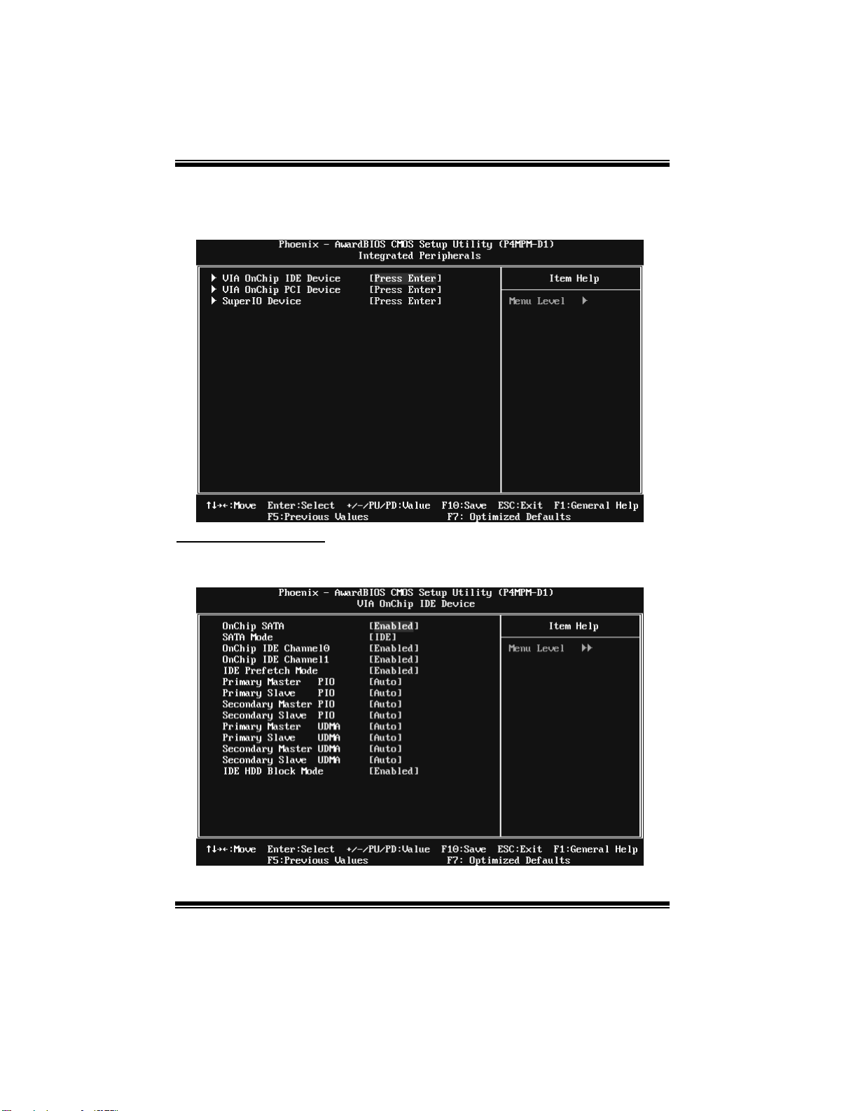
P4M800Pro-D1 BIOS SETUP
5 Integrated Peripherals
Figure 5. Integrated Periph erals
VIA OnChip IDE Device
If you highlight the literal “Press Enter” next to the “ VIA OnChip IDE Device” label and
then press the enter key, it will take you a submenu with the following options:
21
Page 66

P4M800Pro-D1 BIOS SETUP
OnChi p SATA
This option a l lows you to en abl e t he on chip Seri al ATA .
The Choices: Enabled (defaul t), Dis abled.
SATA Mode
This option a l lows you to sel ec t SA TA Mo de .
The Choices: IDE (defaul t), RAID.
OnChip IDE Channel 0/1
The mo th erboard chipset contai ns a PCI IDE interface with support fo r
two IDE channels. Select “Enabled ” to activate the first and/or second IDE
interface. Select “ Disabled” to deactivate an interface if you are going to install a
primary and/or s econdary add-i n IDE interface.
The Choices: Enabled (d efault), Disabled.
IDE Prefetch Mode
The “ onboard ” IDE drive i nterface s upports IDE prefetching for faster drive access.
If t he i nterface d oes not support prefetching, or if you install a primary and/or
secondary add-i n IDE interface, set this option t o “Disab led”.
The Choices: Enabled (defaul t), Dis abled.
Prima ry / Secondary Ma ster / Slave PI O
The IDE PIO (Programmed Input / Output) fields let you set a PIO mode (0-4) for
each of t he IDE devices that the o nboard IDE interface supports. Modes 0 to 4 will
increas e performan ce progressively. In Auto mode, the syst em automatically
determi nes the b est mo de for each d evice.
The Choices: Auto (default), Mode0, Mode1, Mode2, Mode3, Mode4.
Prima ry / Secondary Ma ster / Slave UDMA
Ultra DMA/100 functionality can be implemented if it is supported by the IDE hard
drives in your system. As well, your operating environment requires a DMA driver
(Windows 95 OSR2 or a third party IDE bus master driver). If your hard drive and
your system software both support Ultra DMA/100, select Auto to enable BIOS
support .
The Choices: Auto (d efault ), Disabl ed.
IDE HDD Block Mode
Block mode is also called block transfer, multiple commands, or multiple sector
read / write. If your IDE hard drive supports block mode (most new drives do),
select Enabled for automatic detection of the optimal number of block mode (most
new drives do), select Enabled for automatic detection of the optimal number of
block read / write per sector where the drive can support.
The Choices: Enabled (defaul t), Dis abled.
22
Page 67

P4M800Pro-D1 BIOS SETUP
VIA OnChip PCI Device
If you highlight the literal “Press Enter” next to the “ VIA OnChip PCI Device” label and
then press the enter key, it will take you a submenu with the following options:
VIA-3058 AC97 Audio
This option a l lows you to con t rol the onboard A C97 au di o .
The Choices: Auto (d efault ), Disabl ed.
VIA-3068 MC97 Modem
This option a l lows you to con t rol the onboard MC97 mo d em.
The Choices: Auto (d efault ), Disabl ed.
VIA-3043 OnChip LAN
This option a l lows you to con t rol the onboard VIA -304 3 On Chi p L AN.
The Choices: Enabled (d efault), Disabled
Onboard Lan B oot ROM
Decide whether to invoke the boot ROM of the onboard LAN chip.
The Choices: Disable (default), Enabled.
OnChip USB Controller
This option should be enabled if your system has a USB installed on the system
board. You will need to disable this feature if you add a higher performance
controller.
The Choices: All Enabled (default), All Disabled, 1&2 USB Port, 2&3 USB Port,
1&3 USB Port, 1 USB Port, 2 USB Port, 3 USB Port.
23
Page 68

P4M800Pro-D1 BIOS SETUP
Onchip EHCI Controller
This item allows you to enable or disable the onchip EHCI controller.
The Choices: Enabled (defaul t), Dis abled.
USB Emulation
The Choices:
ON (default) Support USB legacy Keyboard, Mouse and Storage.
OFF Do not support any USB device on Dos.
KB/MS Support USB legacy Keyboard and Mouse, NO support USB
Storag e.
USB Mo use/Keyboa rd Support
Enables support for USB attached mouse/keyboard.
The Choices: Enabled (defau lt ), Dis abled
Super IO Device
Press Enter to configure the Super I/O Device.
Onboard FDC Controller
Select Enabled if your system has a floppy disk controller (FDC) installed on the
system board and you wish to use it. If install and FDC or the system has no floppy
driv e, s el ect D isa bl ed i n this field.
The Choices: Enabled (d efault), Disabled.
24
Page 69

P4M800Pro-D1 BIOS SETUP
Onboard Serial Port 1
Select an address and corresponding interrupt for the first and second serial ports.
The Choices: 3F8/IRQ4 (default), Disabled, Auto, 2F8/IRQ3, 3E8/IRQ4,
2E8/IRQ3.
Onboard Parallel Port
This item al lows you to determine access onboard parallel port controller with which
I/O Address.
The Choices: 378/IRQ7 (default), 278/IRQ5, 3BC/IRQ7, Disabled.
Parallel Port Mode
The default value is SPP.
The Choices:
SPP (default) Using Parallel Port as Standard Printer Port.
EPP Using Parallel P ort as Enhanced Parallel Port.
ECP Using Parallel Port as Extended Capabilities Port.
ECP+EPP Using Parallel Port as ECP & EPP mode.
ECP Mode Use DMA
Select a DMA Channel for the port.
The Choices: 3 (default), 1.
25
Page 70

P4M800Pro-D1 BIOS SETUP
6 Power Management Setup
The Power Management Setup Menu allows you to configure your system to utilize
energy conservation and power up/power down features.
Figu re 6: Power Management S etu p
ACPI f unction
This item displays the status of the Advanced Configuration and Power Management
(ACPI).
The Choices: Enabled (default), Disabled.
Power Man agement Op ti on
This category allows you to select the type (or degree) of power saving and is directly
related to the following modes:
1.HDD Power Down.
2.Suspend Mode.
There are four options of Power Management, three of which have fixed mode settings
Min. Saving
Minimum power management.
Suspend Mode = 1 hr.
HDD Power Down = 15 min
26
Page 71

P4M800Pro-D1 BIOS SETUP
Max. Saving
Maximu m power management only available for sl CPU’s.
Suspend Mode = 1 min.
HDD Power Down = 1 min.
User Define (default)
Allow s you to set each mode individually.
When not disab led, each of the ranges are from 1 min . to 1 hr. except for HDD Power
Down which ranges from 1 min. to 15 min. and disable.
HDD Power Down
When enabled, the hard disk drive will power down and after a set time of system
inactivity. All other devices remain active.
The Choices: Dis abled (default), 1 Min, 2 Min, 3 Min, 4 Min, 5 Min, 6 Min, 7 Min, 8
Min, 9 Min, 10 Min, 11 Min, 12 Min, 13 Min, 14 Min, 15 Min.
Suspend Mode
The item allows you to select the suspend type under ACPI operating system.
The Choices: Dis abled (default), 1 Min, 2 Min, 4 Min, 6 Min, 8 Min, 10 Min,
20 Min, 30 Min, 40 Min, 1 Hour.
Vid eo O ff Op tion
This field determines when to activate the video off feature for monitor power
management.
The Choices: Suspend→Of f (d efau lt) , A lways on.
Video Off Method
This option d eter min es th e man ner i n whi ch the monito r is go es blank.
V/H SYNC+Blank (default)
This selection will cause the system to turn off the vertical and horizontal
synchronization ports and write blanks to the video buffer.
Blank Screen
This option o nly w rites bl ank s to the video bu ffer .
DPMS Support
Initial display power management signaling.
27
Page 72

P4M800Pro-D1 BIOS SETUP
MODEM Use IRQ
This determines the IRQ, which can be applied in MODEM use.
The Choices: 3 (default)/ 4 / 5 / 7 / 9 / 10 / 11 / NA.
Soft-Off b y PWR-BTN
Pres sing t he power button fo r mo re than 4 seconds fo rces the system to enter the
Soft-Off state when the system has “hung”.
The Choices: Instant-Off (default), Delay 4 Sec.
Ac Loss Auto Restart
This field determines the action the system will automatically take when power is
restored to a system that had lost power previously without any subsequent manual
interven tion. There are 3 so urces that provide curren t to the CMOS area that retains these
P ower-On instru ctio ns; the mot he rbo ard battery (3 V), the P ower S u pply (5 VSB), an d t he
Power Supply (3.3V). While AC is not supplying power, the motherboard uses the
motherboard battery (3V). If AC power is supplied and the Power Supply is not turned
on, 5VSB from the Power Supply is used. When the Power Supply is eventually turned
on 3.3V from the Power Supply will be used.
There are 3 options: “Former-Sts”, “On”, “Off”.
“Off” (default) Means always set CMOS to the “Off” status when AC power is lost.
“On” Means always set CMOS to the “On” status when AC power is lost.
“Former-Sts” Means to maintain the last status of the CMOS when AC power is lost.
For example: If set to “ Former-Sts” and AC power is lost when system is live, then after
AC power is restored, the system will automatically power on. If AC power is lost when
system is not live, system will remain powered off.
Delay Prior to T hermal
Set this item to enable the CPU Thermal function to engage aft er the specified
time.
The Choices : 4 Min, 8 Min, 16Min (default), 32 Min.
28
Page 73

P4M800Pro-D1 BIOS SETUP
IRQ /Even t Activity Detect
If you highlight the literal “Press Enter” next to the “ IRQ/Event Activity Detect” label
and then press the enter key, it will take you a submenu with the following options:
VG A
When set to On, any event occurring at a VGA P ort will awaken a system which has
been powered down.
The Choices: Off (defaul t), On.
LPT & COM
When th is op ti on is set to O n , any ev ent o ccurrin g at a COM (s erial)/ LP T ( print er)
port will awaken a system which has been powered down.
The Choices: LPT/COM (defaul t), COM, LP T, NON E.
HDD & FDD
When this option is set to On, any event occurring on a hard drive or a floppy drive
will awaken a system which has been powered down.
The Choices: On (defaul t), Off.
PCI Master
When set to On, you need a LAN add-on card which supports the power function. It
should also support the wake-up on LAN jump.
The Choices: Off (defaul t), On.
29
Page 74

P4M800Pro-D1 BIOS SETUP
PowerOn by PCI Card
When you sel ect Enabled, a P ME signal fro m PCI card returns th e system t o Full
ON state.
The Choices: Disabled (default), Enabled.
Modem Ring Resume
This item allows you to disable or enable Modem Ring Resume function.
The Choices: Disabled (default), Enabled.
RTC Alarm Resume
When “Enabled”, you can set the d ate and time at which the RTC (real-t ime clock)
alarm awakens the system fro m Suspen d mode.
The Choices: Disabled (default), Enabled.
Date (of Mo nth)
You can choose which month the system will boot up. This field is only
configurable when “RTC Resume” is set to “Enabled”.
Resume Time (hh:mm:ss)
You can choose the hour, minute and second the system will boot up. This field is
only configurable when “ RTC Resume” is set to “Enabled”.
30
Page 75

P4M800Pro-D1 BIOS SETUP
IRQ s A ctivity Monitoring
Pres s Enter to access an other sub men u used to configure th e different w ake up
events (i.e. wake on LPT & COMM activity).
Primary INTR On
IRQ3 (COM2) Disabled
IRQ4 (COM1) Enabled
IRQ5 (LPT2) Enabled
IRQ6 (Floppy Disk) Enabled
IRQ7 (LPT1) Enabled
IRQ8 (RTC Alarm) Disabled
IRQ9 (IRQ2 Redir) Disabled
IRQ10 (Reserved) Disabled
IRQ11 (Reserved) Disabled
IRQ12 (PS/2 Mouse) Enabled
IRQ13 (Coprocessor) Enabled
IRQ14 (Hard Disk) Enabled
IRQ15 (Reserved) Disabled
31
Page 76
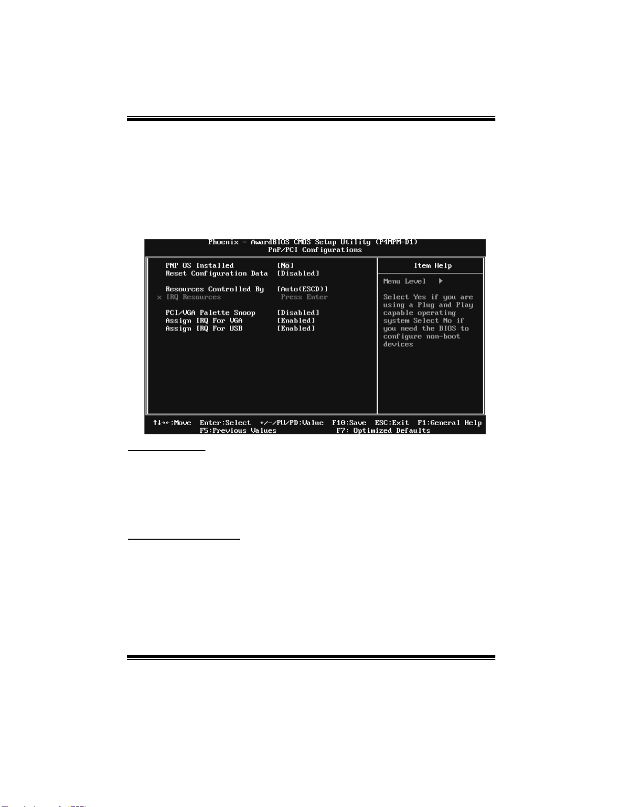
P4M800Pro-D1 BIOS SETUP
7 PnP/PCI Configurations
This section describes configuring the PCI bus system. PCI, or Personal Computer
Interco nnect, is a system wh ich al lows I/O devices to operate at speeds nearing the speed o f
the CPU itself uses when communicating with its own special components. This section
covers some v ery technical items and it i s s trongly recommend ed that only experienced
users should make any changes to the default settings.
Figure 7: PnP/PCI Configurations
PNP OS Installed
When s et to YES, BIO S will only init ial i ze the PnP cards us ed for the b oo t s equ ence (VG A,
IDE, SCSI). The rest of the cards will be initialized by the PnP operating system like
Window™ 95. When set to NO, BIOS will initialize all the PnP cards. For non-PnP
operating systems (DOS, Netware™ ), this option must set to NO.
The Choices: No (default), Yes.
Reset Configuration Data
The system BIO S supports the PnP feature which requires the system to record w hich
resources are assigned and protects resources from conflict.
Every peripheral device has a node, which is called ESCD. This node records which
resources are assigned to it. The system need s to reco rd and update ESCD to the me mory
locat ions. Thes e lo cations (4K) are reserved in the s ystem BIOS. If the Disabled (default)
option is chosen, the system‘s ESCD will update only when the new configuration varies
from the last one. If the Enabled option is chosen, the system is forced to update ESCDs
and then is automatically set to the “Disabled” mode.
32
Page 77

P4M800Pro-D1 BIOS SETUP
The above settings will be shown on the screen only if “ Manual” is chosen for the resources
controlled by function.
Legacy is the term, which signifies that a resource is assigned to t he ISA Bus and provides
non-PnP ISA add-on cards. P CI / ISA P nP signifies that a resou rce is as signed to the PCI
Bus or provides for ISA PnP add-on cards and peripherals.
The Choices: Disabled (default), Enabled.
Resources Controlled B y
By Choosing “Auto(ESCD)” (d efau lt), the system BIOS will detect the system resources
and automatically assign the relative IRQ and DMA channel for each peripheral. By
Choosing “Manual”, the user will need to assign IRQ & DMA for add-on cards. Be sure
that there are no IRQ/DMA and I/O port conflicts.
The Choices: Auto (ESCD) (default), Manual.
IRQ Resou rces
This submenu will allow you t o assign each system in terrupt a type, dep ending on the type
of device using the interrupt. When you press the “Press Enter” tag, you will be directed to
a submenu that will allow you to configure the system interrupts. This is only
configurable when “Resources Controlled By” is set to “Manual”.
IRQ-3 assigned to PCI Device
IRQ-4 assigned to PCI Device
IRQ-5 assigned to PCI Device
IRQ-7 assigned to PCI Device
IRQ-9 assigned to PCI Device
IRQ-10 assigned to PCI Device
IRQ-11 assigned to PCI Device
IRQ-12 assigned to PCI Device
IRQ-14 assigned to PCI Device
IRQ-15 assigned to PCI Device
PCI / VGA Palette Snoop
Choose Disabled or Enabled. Some graphic controllers which are not VGA compatible
take the output from a VGA controller and map it to their display as a way to provide boot
information and VGA compatibility.
However, the color information coming from the VGA controller is drawn from the palette
table inside the VGA controller to generate the proper colors, and the graphi c co ntroller
needs to know what is in the palette of the VGA controller. To do this, the non-VGA
graphic controller watches for the Write access to the VGA palette and registers the snoop
data. In PCI based systems, where the VGA controller is on the PCI bus and a non-VGA
Graphic controller is on an ISA bus , the Write Access to t he palette will not show up on the
ISA bus if the PCI VGA controller responds to the Write.
33
Page 78

P4M800Pro-D1 BIOS SETUP
In th is cas e, t h e P CI VGA co ntroller sh ould no t r esp ond to t he W rit e, i t s hould only sn oop
the data and permi t the access to be forwarded to the ISA bus . The non-VGA ISA graphic
controller can then snoop the data on the ISA bus. Unless you have the above situation,
you should disable this option.
Disabl ed (default) Disables the function.
Enabled Enables the function.
Assign IRQ For VGA
This item allows the users to choose which IRQ to assign for the VGA.
The Choices: Enabled (defaul t), Dis abled.
Assign IRQ For USB
This item allows the users to choose which IRQ to assign for the USB.
The Choices: Enabled (defaul t), Dis abled.
34
Page 79

P4M800Pro-D1 BIOS SETUP
8 PC Health Status
Figure 8: PC Health Status
CPU SMART FAN Control by
Choose “ smart” to reduce the noise caused by CP U FAN.
The Choices: Smart, Always On (defaul t).
CPU Fan Off<℃>
If the CPU Temperature is lower than the set value, FAN will turn off.
The Choices: Min=0; Max=127; Key in a DEC number.
CPU Fan Start<℃>
CPU fan starts to work under smart fan function when arrive this set value.
The Choices: Min=0; Max=127; Key in a DEC number.
CPU Fan Full speed <℃ >
When CPU temperature is reach the set value, the CPU fan will work under Full Speed.
The Choices: Min=0; Max=127; Key in a DEC number.
35
Page 80

P4M800Pro-D1 BIOS SETUP
Start PWM Value
When CPU temperature arrives to the set value, the CPU fan will work under Smart Fan
Function mode. The range is from 0~127, with an interval of 1.
The Choices: Min=0; Max=127; Key in a DEC number.
Slope PWM
Increasing the value of slope PWM will rai se the speed o f CP U fan.
The Choices: 1 PWM Value/℃ (defaul t), 2 PWM Value/℃, 4 PWM Value/℃, 8 PW M
Val ue/ ℃,16 P W M Val ue/℃,32 PW M Value/℃, 6 4PW M Value/℃.
Shutdown Temperature
This item allows you to set up the CPU shutdown Temperature. This item only effective
under Windows 98 ACPI mode.
The Choices: 90℃ /16 7℉ (default) , 60℃/140℉, 65℃/149℉, 70℃/158℉ , 75℃/167
℉ , 80℃/176℉, 85℃/1 85℉, D isabled.
CPU Vcore,+ 3.3V, +5.0V,+12V, DRAM Voltage,Voltage Battery
Detect the s ystem’s voltag e and battery status automatically.
Current CPU Temp
This field displays the current temperature of CPU.
Current CPU FAN S peed
This field displays the current speed of CPU fan.
Current SYS FAN Sp eed
This field displays the current speed SYSTEM fan.
Show H/W Monitor in POST
If you computer contain a monitoring system, it will show PC health status during POST
stage. The item offers several delay time to select you want.
The Choices: Enabled (d efault), Disabled.
Chassis Open Warning
This item al lows you to enable or disable Chassis Open Warning b eep.
The Choices: Disabled (default)., Enabled.
36
Page 81

P4M800Pro-D1 BIOS SETUP
9 Frequency/ Voltage Control
Figure 9: Frequency/ Voltage Control
CPU CLOCK
This item allows you to select CPU Clock, and CPU over clocking.
Min= 100 Max= 400 Key in a DEC number.
The Choices: 100Mhz (default),.
Spread Spectrum
This item allows you to enable/disable the Spread Spectrum function.
The Choices: +/-0.25% (default), -0 .5%, -1.0 %, +/-0.5%, D isabled .
CPU Clock Ratio
This item allows you to select the CPU Ratio.
Min= 8 Max= 50 ; Key in a DEC number.
The Choices: 8X (default).
DDR Voltage Regulator
This item al lows you to select DDR Voltage.
The Choices: 2.6V (default), 2.9V, 2.8V, 2.7V.
CPU Voltage Regulator
This item allows you to select CPU Voltage.
The Choices: StartUp (default), +0.012V~+0.787V.
37
Page 82

P4M800Pro-D1 BIOS SETUP
Specia l N otice:
If unfortunately, the system’s frequency that you are selected is not
functioning, there are two methods of booting-up the system.
Method 1:
Clear the COMS data by setting the JCOMS1 ((2-3) closed)) as “ON”
status. All the CMOS data will be loaded as defaults setting.
Method 2:
Press the <Insert> key and Power button simultaneously, after that
keep-on pressing the <Insert> key until the power-on screen showed.
This action will boot-up the system according to FSB of th e proces sor.
38
 Loading...