

Page 1

P4M800-M7A BIOS SETUP
BIOS Setup........................................................................................1
1 Main Menu.....................................................................................................3
2 Standard CMOS Features ..............................................................................6
3 Advanced BIOS Features...............................................................................8
4 Advanced Chipset Features..........................................................................13
5 Integrated Peripherals ..................................................................................18
6 Power Management Setup ...........................................................................23
7 PnP/PCI Configurations...............................................................................29
8 PC Health Status .......................................................................................... 32
9 Frequency/ Voltage Control.........................................................................34
i
Page 2

P4M800-M7A BIOS Manual
BIOS Setup
Introduction
T his manu al discussed Aw ard™ Set up pr ogra m bu ilt into the ROM BI OS . The Setup
program allows users to modify the basic system configuration. This special information is
th en stored in ba tt ery-bac ke d RAM s o that it retain s t he Setup info rmation w hen the po wer
is turned off.
T he Award BIO S™ installed in you r comput er system’s ROM (Re ad O nly Mem ory) is a
custom version of an industry standard BIOS. This means that it supports Intel Pentium
processor input/output system. The BIOS provides critical low-level support for standard
devices such as disk drives and serial and parallel ports.
Adding important has customized the Award BIOS™, but nonstandard, features such as
virus and password protection as well as special support for detailed fine-tuning of the
chipset controlling the entire system.
The rest of this manual is intended to guide you through the process of configuring your
system using Setup.
Plug and Play Support
These AWARD BIOS supports the Plug and P lay Version 1.0A specification. ESCD
(Extended System Configuration Data) write is supported.
EPA Gree n PC Support
This AWARD BIOS supports Version 1.03 of the EPA Green PC specification.
APM Support
These AWARD BIOS supports Version 1.1&1.2 of the Advanced Power Management
(APM) specification. Power management features are imp lemented via the System
Management Interrupt (SMI). Sleep and Suspend power management modes are supported.
Power to the hard disk drives and video monitors can be managed by this AWARD BIOS.
ACPI Support
Award ACPI BIOS support Version 1.0 of Advanced Configuration and Power interface
specif ication (ACPI). It provides ASL code for power management and device
configuration capabilities as defined in the ACPI specification, developed by Microsoft,
Intel and Toshiba.
®
4
1
Page 3

P4M800-M7A BIOS Manual
PCI Bus Suppo rt
This AWARD BIOS also supports Version 2.1 of the Intel PCI (Peripheral Component
Interconnect) local bus specification.
DRAM Support
DDR SDRAM (Double Data Rate Synchronous DRAM) are supported.
Supported CPUs
This AWARD BIOS supports the Intel CPU.
Us i ng Setu p
In general, you use the arrow keys to highlight items, press <Enter> to select, use the
<PgUp> and <P gDn> keys to change entries, press <F1> for help and press <Esc> to quit.
The followin g table provides more detail about how to navigate in the Setup program by
using the keyboard.
Keystroke Function
Up arrow Move to p revio us item
Down arrow Move to next item
Left arro w Move to the ite m o n the left (menu bar)
Right arrow Move to t he item on the right (menu bar)
Move Enter Move to the item you desired
PgUp key Increase the numeric value or make changes
PgDn key Decrease the numeric value or make changes
+ Key Increase the numeric value or make changes
- Key Decrease the numeric value or make changes
Esc key Main Menu – Quit a nd not save changes into CMOS
F1 k ey Genera l help o n Setup navi gatio n k eys
F5 key Load previous values from CMOS
F7 key Load the optimized defaults
F10 key Save all the CMOS changes and exit
Status Page Setup Menu and Option Page Setup Me nu – Exit
Current page and return to Main Menu
2
Page 4
P4M800-M7A BIOS Manual
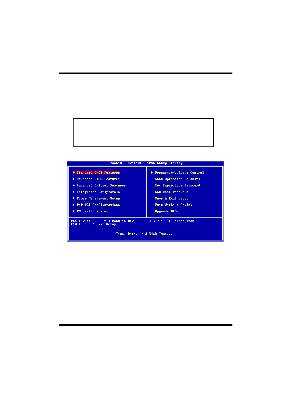
1 Main Menu
Once you enter Award BIOS™ CMOS Setup Utility, the Main Menu will appear on the
screen. The Main Menu allows you to select from several setup functions. Use the arrow
keys to select among the items and press <Enter> to accept and enter the sub-menu.
!! WARNING !!
The information about BIOS defaults on manual (Fi gu re
1,2,3,4,5,6,7,8,9) is just for reference, please refer to the BIOS
installed on board, for update information.
Figure 1. Main Menu
Standard CMOS Features
This submenu contains industry standard configurab le options.
Advanced BIOS Features
This submenu allows you to configure enhanced features of the BIOS.
Advanced Chipset Features
This submenu allows you to configure special chipset features.
Integrated Peripherals
This submenu allows you to configure certain IDE hard drive options and Programmed
Input/ Output features.
3
Page 5

P4M800-M7A BIOS Manual
Power Management Setup
This submenu allows you to configure the power management features.
PnP/PCI Configurations
This submenu allows you to configure certain “Plug and Play” and PCI options.
PC Health Status
This submenu allows you to monitor the hardware of your system.
Freque ncy/ Voltage Control
This submenu allows you to change CPU Vcore Voltage and CP U/PCI clock. (However,
this function is strongly recommended not to use. Not properly change the voltage
and clock may cause the CPU or M/B damage!)
Lo ad Opti mize d D e fa u l ts
This selection allows you to reload the BIOS when the system is having problems
particu larly with the boot sequence. These configurations are factory settin gs optimized
for this system. A confirmation message will be displayed before defaults are set.
Set Supervisor Password
Setting the supervisor password will prohibit everyone except the superv isor from making
changes usin g the CMOS Setup Utility. You will be prompted with to enter a password.
4
Page 6

P4M800-M7A BIOS Manual
Set User Password
If the Supervisor Password is not set, then the User Password will function in the same way
as the Supervisor Passw ord. If the Su pe rvisor Pa sswor d is set and the User Passwor d is
set, the “User” will only be able to view configurations but will not be able to change them.
Save & Exit Setup
Save all configuration changes to CMOS(memory) and exit setup. Confirmation message
will be displayed before proceeding.
Exit Without Saving
Abandon all changes made during the current session and exit setup. confirmation
message will be displayed before proceeding.
Upgrade BIOS
This submenu allows you to upgrade bios.
5
Page 7
P4M800-M7A BIOS Manual
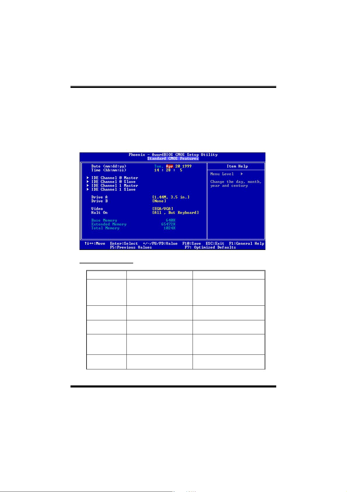
2 Standard CMOS Features
The items in Standard CMOS Setup Menu are divided into 10 categories. Each category
includes no, one or more than one setup items. Use the arrow keys to highlight the item and
then use the<PgUp> or <P gDn> keys to select the value you want in each item.
Figure 2. Standard CMOS Setup
Main Menu Selections
This table shows the selections that you can make on the Main Menu.
Item Options Description
Date mm : dd : yy Set the system date. Note
that the ‘Day’ automatically
changes when you set the
date.
Time hh : mm : ss Set the system internal
clock.
IDE Primary
Master
IDE Primary
Slave
IDE Secondary
Master
Options are in its sub
menu.
Options are in its sub
menu.
Options are in its sub
menu.
Press <Enter> to enter the
sub menu of detailed options
Press <Enter> to enter the
sub menu of detailed
options.
Press <Enter> to enter the
sub menu of detailed
6
Page 8

P4M800-M7A BIOS Manual
options.
IDE Secondary
Slave
Drive A
Drive B
Video EGA/VGA
Halt On All Errors
Base Memory N/A Displays the amount of
Extended
Memory
Total Memory N/A Displays the total memory
Options are in its sub
menu.
360K, 5.25 in
1.2M, 5.25 in
720K, 3.5 in
1.44M, 3.5 in
2.88M, 3.5 in
None
CGA 40
CGA 80
MONO
No Errors
All, but Keyboard
All, but Diskette
All, but Disk/ Key
N/A Displays the amount of
Press <Enter> to enter the
sub menu of detailed
options.
Select the type of floppy disk
drive installed in your
system.
Select the default video
device.
Select the situation in which
you want the BIOS to stop
the POST process and
notify you.
conventional memory
detected during boot up.
extended memory detected
during boot up.
available in the system.
7
Page 9
P4M800-M7A BIOS Manual
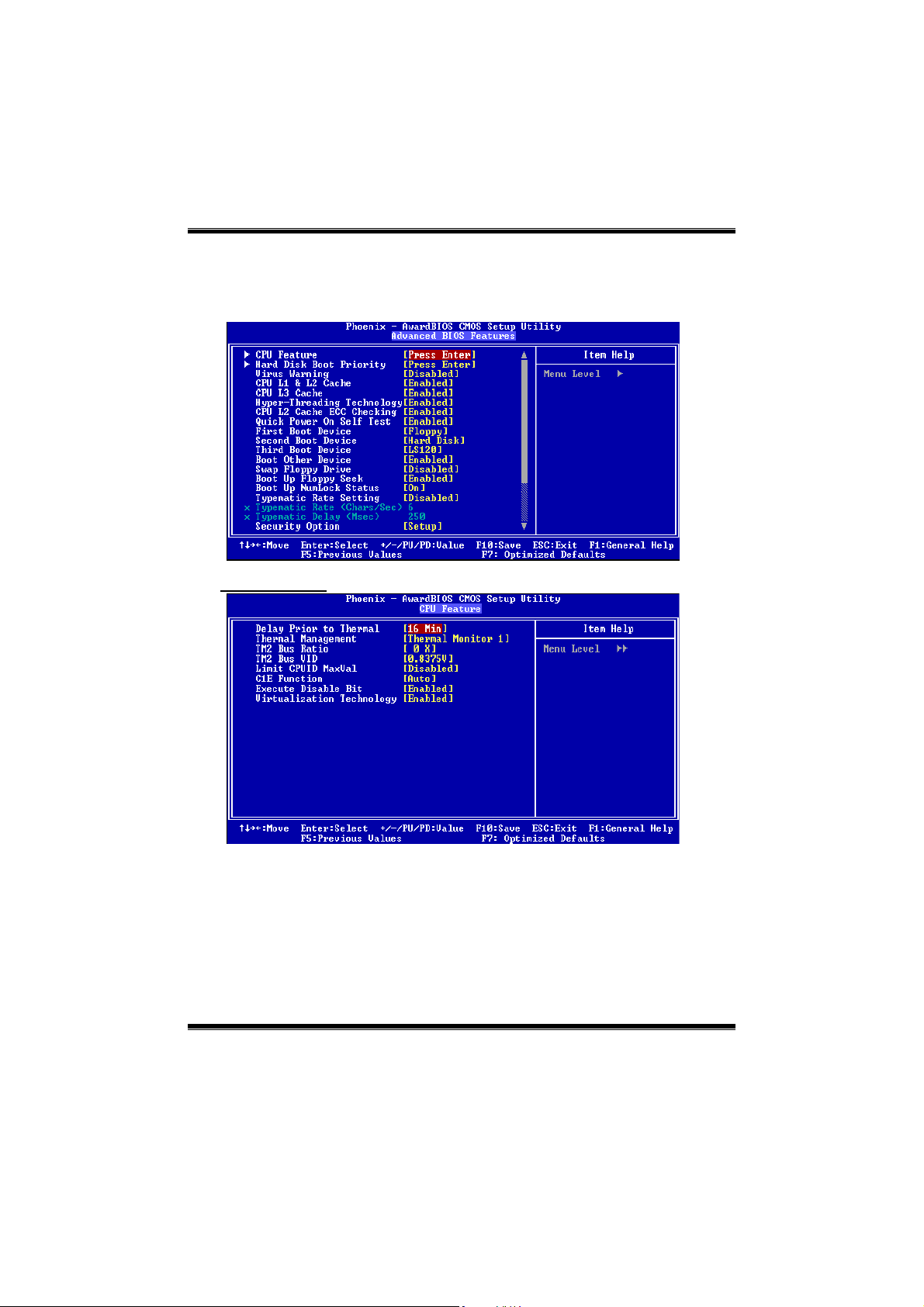
3 Advanced BIOS Features
Fig ure 3. Adva nce d BIOS Se tup
CPU FEATURE
Delay Prior to Thermal
Set this item to enable the CPU Thermal function to engage after the specified time.
The Choices: 4, 8, 16 (default), 32.
Thermal Manage ment
Allow you to choose the thermal management method of your monitor.
The Choices: Thermal Monitor 1 (d efa ult ), T hermal Mo nitor2.
Notes: The choices will be different according to your CPU features.
8
Page 10
P4M800-M7A BIOS Manual
TM2 B us R ati o
Represents the frequency. Bus ratio of the throttled performance state that will be
in it iated whe n th e on-die s ensor goe s f rom no t h ot to hot.
The Choices: 0X (default).
TM2 Bus VID
Represents the voltage of the throttled performance state that will be initiated when
the on-die sensor goes from not hot to hot.
The Choices:0.8375 (defa ult) .
Limit CPU ID Ma x Val
S et limit CP U I D maximum va le to 3 , it sh ould be disa ble d for Win XP.
The Choices: Disabled (default), Enabled.
C1E Func tion
The Choices: Auto (default).
Exec ute Disa ble B it
When disabled ,forces the XD feature flag to always return 0.
The Choices: Disabled, Enabled(default).
Virtualization Technology
The Choices: Disabled, Enabl ed (default).
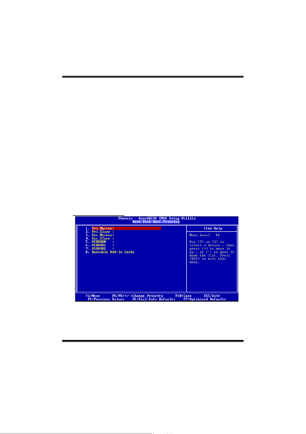
Hard Disk Boot Priority
These BIOS attempt to load the operating system from the device in the sequence selected
in these items.
The Choices: P ri. Master, Pri.Slave, Sec.Master, Sec. Slave, USBHDD0, USBHDD1,
USBHDD2 and
Bo otable Add-in Cards.
9
Page 11

P4M800-M7A BIOS Manual
Virus Warning
T his option al lows you to c hoose th e Virus Wa rning featu re t hat is use d t o protect th e IDE
Hard Disk boot sector. If this function is enabled and an attempt is made to write to the
boot sector, BIOS will display a warning message on the screen and sound an alarm beep.
Disabled (default) Virus protection is disabled.
Enabled Virus protection is activated.
CPU L1&L2 Cache
Depending on the CPU/chipset in use, you may be able to increase
memory access time with this option.
En ab le d (default) Enable cache.
Disabled Disable cache.
CPU L3 Cache
Depending on the CPU/chipset in use, you may be able to increase
memory access time with this option.
En ab le d (default) Enable cache.
Disabled Disable cache.
Hyper-Threading Technology
This option allows you to enable or disabled CPU Hyper-Threading.
Enabled for Windows XP and Linux 2.4.x (OS optimized for Hyper
Threading Technology. Disabled for other OS (OS not optimized for
Hyper Threading T echnology.
The Ch o ices: En a ble d (Default), Disabled.
CPU L2 Cache ECC Checking
Th is ite m allows y ou to ena ble/disab le CP U L2 C ache EC C Checkin g.
The Ch o ices: En a ble d (default), Disabled.
Quick Power On Self Test
Enablin g this option will cause an abridged version of the Power On Self-Test (POST) to
execute after you power up the computer.
First/ Se co nd/ T hird/ Boot O the r Device
These BIOS attempt to load the operating system from the device in the sequence selected
in these items.
The Ch o ices: Floppy, LS120, HDD-0, SCSI, CDROM, HDD-1, HDD-2, HDD-3, IP100,
Enabled (default) Enable quick POST.
Disabled Normal POST.
LAN, HPT 3 70, Disabled, Enabled
10
Page 12

P4M800-M7A BIOS Manual
Swap Floppy Drive
For systems with two floppy drives, this option allows you to swap logical drive
assignments.
The Choices :Disabled (default), Enabled.
Boot Up Floppy Seek
Enabling th is option will test the floppy drives to determine if they have 40 or 80 tracks.
Disabling this option reduces the time it takes to boot-up.
The Ch o ices:Enable d (Default), Disab led.
Boot Up NumLock Status
Selects the NumL ock. State after power on.
Th e Cho i ce s : On (default) Numpad is number keys.
Off Numpad is arrow keys.
Typematic Rate Se tt ing
When a key is held down, the keystroke will repeat at a rate determined by the keyboard
controller. When enabled, the typematic rate and typematic delay can be configured.
The Cho ices:Disabled (default), Enabled.
Typematic Rate (Chars/Sec)
Sets the rate at which a keystroke is repeated when you hold the key down.
Th e Cho i ce s : 6 (default), 8, 10, 12, 15, 20, 24, 30.
Typematic Delay (Msec)
Sets the delay time after the key is held down before it begins to repeat the keystroke.
The Choices:250 (default), 500,750,1000.
Security Option
Th is option w ill e nable o nly ind iv idu a ls with pas swords to br in g the syst em online a nd/or to
use the CMOS Setup Utility.
MPS Ve rsio n Co nt ro l Fo r OS
The BIOS supports version 1.1 and 1.4 of the Intel multiprocessor specif ication.Select
version supported by the operation system running on this computer.
The Ch o ices: 1.4 (default), 1.1.
System A password is required for the system to boot and is
also required to access the Setup Utility.
Setup (default) A password is requ ired to access the Setup Utility
only.
This will only apply if passwords are set from the Setup main menu.
11
Page 13

P4M800-M7A BIOS Manual
OS Select For DRAM > 64MB
A choice other than Non-OS2 is only used for OS2 systems with memory exceeding
64MB.
The Choices: Non-OS2 (d efault), OS2.
Video BIOS Shadow
The Choices: Enabled (default), Disabled.
Delay For HDD<Secs>
The Choices: 0 (default)
Small Logo (EPA) Show
T his item allows you to se lect whet her the “Sma ll Logo” sho ws.
Enabled (default) “Small Logo” shows when system boots up.
Disabled No “Small Logo” shows when system boots up.
S UMM AR Y SCREE N SHOW
This item allows you to enable/disable the summary screen. Summary
screen means system configuration and P CI device list ing.
The choices: En ab led, Disabled (default).
12
Page 14

P4M800-M7A BIOS Manual
4 Advanced Chipset Features
This submenu allows you to configure the specific features of the chipset installed on your
system. This chipset manage bus speeds and access to system memory resources, such as
DRAM. It also coordinates communications with the PCI bus. The default settings that came
with your system have been optimized and therefore should not be changed unless you are
suspic ious that the settings have been changed incorrectly.
Fig ure 4. Adva nce d Chipse t Setup
DR AM Clock /D rive Co ntrol
13
Page 15

P4M800-M7A BIOS Manual
To control the Clock/Drive. If you highlight the litera l “Press Enter” next to the “DRAM
Clock/Drive Control” label and then press the enter key, it will take you a submenu with the
following options:
DRAM Clock
This item determines DRAM clock following 100MHz, 133MHz, 166MHz or By SPD.
The Choices: 100MHz, 133MHz, By SPD (default), 166MHz.
DRAM Timing
This item dete rmines DR AM c loc k/ tim in g fo llow SPD or n ot.
The Choices: Auto By SPD (defa ult) , M anual, T urbo, Ultra.
SDRAM CAS Latency
When SDRAM is installed, the number of clock cycles of CAS latency depends on the
SDRAM timing.
The Choices: 2.5 (default), 2.
Bank Interleave
This item allows you to enable or disable the bank interleave feature.
The Choices: Disabled (default), 2 bank, 4 bank.
Prec harge to Act ive (T rp)
This items allows you to specify the delay from precharge command to activate
command.
The Choices: 2T, 3T, 4T(default), 5T.
Active to Precharge (Tras)
This items allows you to specify the minimum bank active time.
The Choices: 7T(default), 6T.
Acti ve to CM D (Trcd)
Use this item to specify the delay from the activation of a bank to the time that a read or
write command is accepted.
The Choices: 2T, 3T, 4T(default), 5T.
REF to ACT/REF to REF (Trfc)
The Choices: 15T (defa ult).
ACT (0) to ACT(1) (TRRD)
The Choices: 3T (default).
Rea d to Precharge < Trtp>
The Choices: 2T (default).
Wri t e to Read <T Wtr>
The Choices: 1T (default).
14
Page 16

P4M800-M7A BIOS Manual
Write Recovery Time<TWr>
The Choices:4T (default).
DRAM Com mand Rate
This item controls clock cycle that must occur between the last valid write operation and
the next command.
The Cho ices: 1T Command, 2T Co mmand (default).
RDSAIT Mode
The Choices: Auto(default).
RDSAIT Selection
The Choices:03(default)
AGP & P2 P Bridge Contro l
If you highligh t t he literal “P re ss Enter” ne xt to t he “AGP & P2P Br idge Control” la be l and
AGP Aperture Size
Select the size of the Accelerated Graphics Port (AGP) aperture. The aperture is a portion
The Cho ices: 64M, 256M, 128M (default), 32M, 16M, 8M, 4M.
AGP 2.0 Mode
This item allows you to select the AGP Mode.
The C ho ice s: 4X (default), 2X, 1X.
AGP Driving Control
By choosing “Auto” the system BIOS will the AGP output Buffer Drive strength P
The Choices: Auto (default), Manual.
then press the enter key, it will take you a submenu with the follow ing options:
of the PCI memory address range dedicated for graphics memory address space. Host
cycles that hit the aperture range are forwarded to the AGP without any translation.
Ctrl by AGP Card. By choosing “Manual”, it allows user to set AGP output Buffer Drive
strength P Ctrl by manual.
15
Page 17

P4M800-M7A BIOS Manual
AGP Driving Value
While AGP driv ing contr ol it em set to “M anua l”, it allow s user to set AGP drivin g.
The Choices: DA (default).
AGP Fast Write
The Choices: Enabled, Disabled (default).
AGP Ma s t er 1 WS Wr ite
When Enabled, writes to the AGP (Accelerated Graphics Port) are executed
with one-wait states.
The Choices: Disabled (default), Enabled.
AGP Master 1 WS Read
When Enabled, read to the AGP (Accelerated Graphics Port) are executed with
one wait states.
The Choices: Disabled (default), Enabled.
AGP 3.0 Calibration cycle
The Choices: Enabled (default),Disabled.
VGA Share Memory Size
The Choices: 64M (default), Disabled.
Direct Frame Buffer
The Choices: Enabled (default),Disabled.
4. 3 CPU & PC I Bus Control
If you highlight the literal “Press Enter” next to the “CPU & PCI Bus Control” label and then
press the enter key, it will take you a submenu with the followin g options:
16
Page 18

P4M800-M7A BIOS Manual
PCI Master 0 WS Write
When enabled, writes to the P CI bus are executed with zero-wait states.
The Cho ices: Ena bl ed (default), Disabled.
PCI Delay Transaction
The chipset has an embedded 32-bit posted write buffer to support delay transactions
cycles. Select Enabled to support compliance with PCI specificat ion.
The Choices: Enabled (default), Disabled.
Vlink mode selection
The Choices:By Auto (default).
VLink 8X Support
This item allows you to enable or disable VLink 8X support.
The Choices: Enabled (default), Disabled.
DRDY-Timing
The Choices: default (def ault)
Memory Hole
When enabled, you can reserve an area of system memory for ISA adapter ROM. When
this area is reserved, it cannot be cached. Refer to the user documentation of the peripheral
you are installing for more information.
The Choices: Disabled (default), 15M – 16M.
System BIOS Cacheable
Select ing the “Enabled” option allows caching of the system BIOS ROM at
F0000h-FFFFFh, which can improve system performance. However, any programs writing
to this area of memory will cause conflicts and result in system errors.
The Choices: Enabled(default), Disab led.
IN IT DISP LA Y F IRST
With systems that have multiple video cards, this option determines whether the primary
disp lay uses a PCI Slot or an AGP Slot.
The Choices: PCI Slot (default), AGP.
17
Page 19

P4M800-M7A BIOS Manual
5 Integrated Peripherals
Figure 5. Integrated Peripherals
VIA OnChip IDE Device
The chipset contains a P CI IDE interface with support for two IDE channels.
Select “Enabled” to activate the first and / or second IDE interface. If you install a primary
and / or secondary add-in IDE interface, select “Disabled” to deactivate an interface. If you
high light the literal “Press Enter” next to the “Onchip IDE Control” label and then press the
enter key, it will take you a submenu with the following options:
18
Page 20

P4M800-M7A BIOS Manual
OnChip SATA
T his option allo ws you to enable the on chip Seria l ATA.
The Choices: Enabled (default), Disabled.
SATA Mode
The Choices: RAID (default).
IDE DMA Transfer Access
The Choices: Enabled (default), Disabled.
IDE Channel 0/1
The motherboard chipset contains a PCI IDE interface with support for
two IDE channels. Select “Enabled” to activate the first and/or second IDE interface.
Select “Disabled” to deactivate an interface if you are going to install a primary
and/or secondary add-in IDE interface.
The Choices: Enabled (default), Disabled.
IDE Prefetch Mode
The “onboard” IDE drive interfaces supports IDE prefetching for faster drive access.
If the interface does not support prefetching. If you install a primary and/or
secondary add-in IDE interface, set this option to “Disabled”.
The Choices: Enabled (default), Disabled.
IDE Primary / Secondary Master / Slave PIO
The IDE PIO (Programmed Input / Output) fields let you set a PIO mode (0-4) for
each of the IDE devices that the onboard IDE interface supports. Modes 0 through 4
provides successively increased performance. In Auto mode, the system
automatically determines the best mode for each device.
The Choices:Auto ( def au lt), Mode0, Mode1, Mo de 2, Mode 3, Mode4.
IDE Primary / Secondary Master / Slave UDMA
Ultra DMA/100 functionality can be implemented if it is supported by the IDE hard
drives in your system. As well, your operating environment requires a DMA driver
(Windows 95 OSR2 or a third party IDE bus master driver). If your hard drive and
your system software both support Ultra DMA/100, select Auto to enable BIOS
support.
The Choices: Auto (default), Disabled.
IDE H DD Bl o ck Mo de
If your IDE hard drive supports block mode, select “Enabled” for automatic
detection of the optima l number of block read/ writes per sector the drive can
support.
The Choices: Enabled (default), Disabled.
19
Page 21

P4M800-M7A BIOS Manual
VIA OnChip PCI Device
If you highlight the literal “Press Enter” next to the “
press the enter key, it will take you a submenu with the follow ing options:
VIA-3058 AC97 Audio
This option allows you to control the onboard AC97 audio.
The Choices: Auto (default), Disabled.
VIA-3068 AC97 Audio
This option allows you to control the onboard AC97 audio.
The Choices: Auto (default), Disabled.
VIA-3043 Onchip LAN
The Choices: Enabled (Default), Disabled.
Onboard LAN Boot ROM
The Choices: Enabled, Disabled(default).
The Cho i ces: Enabled (Default), Disabled.
USB Device Function
The Choices: Enabled, Disabled(default).
This item allows you to enable or disab le the Onboard LAN Boot ROM controller.
Onchip USB Controller
elect “Enabled” if your system contains a Universa l Serial Bus (USB) controller
S
and you have USB peripherals.
The Choices: All Enabled (default), All Disabled.
On-c hip EHC I Cont rolle r
This item allows you to enable or disable the on-chip EHCI controller.
OnC hip PCI Devic e” la be l and t hen
20
Page 22

P4M800-M7A BIOS Manual
USB Emulation
Do not support any USB device on Dos
The Cho ices: On (default), Off.
USB Keyboard/ Mouse Support
This item allows you to enable or disable the USB Keyboard/ Mouse Legacy
Support.
The Choices:Disabled (default), Enabled.
Super IO Device
If you highlight the litera l “P re ss E nter” ne xt t o th e “Super IO Devic e” labe l and then pr ess
the enter key, it will take you a submenu with the following options :
Onboard FDC Controller
Select Enabled if your system has a floppy disk controller (FDC) installed on the
system board and you wish to use it. If install and FDC or the system has no floppy
drive, select Disabled in this f ield.
The Choices: Enabled (default), Disabled.
Onboard Se rial Po rt 1
Select an address and corresponding interrupt for the first and second serial ports.
The Choices:Disabled, 3F8/IRQ4 (default), 2F8/IRQ3, 3E8/IRQ4, 2E8/IRQ3,
Auto.
Onboard Serial Port 2
Select an address and corresponding interrupt for the first and second serial ports.
The Choices:Disabled (default) , 2F8/IRQ3, 3F8/IRQ4, 3E8/IRQ4,2E8/IRQ3,
Auto.
21
Page 23

P4M800-M7A BIOS Manual
UART Mode Select
This item allows you to determine which Infra Red (IR) function of onboard I/O
chip.
The Choices: Normal (default), AS KIR, IrDA.
UR2 Duplex Mode
S
elect the value required by the IR device connected to the IR port. Full-duple x
mode permits simultaneous two-direction transmission. Half-duplex mode permits
transmission in one direction only at a time.
The Choices: Half (default), Full.
Onboar d Pa ra lle l Port
This item allows you to determine access onboard paralle l port controller with which
I/O Addre ss.
The Choices:378/IRQ7 (default), 278/IRQ5, 3BC/IRQ7, Disabled.
Parallel Port Mode
The default value is SPP.
The Choices:
ECP Mode Use DMA
Select a DMA Channel for the port.
The Choices: 3 (default), 1.
Onboard LAN Device
This item allows you to enable or disable the Onboard LAN Device
controller.
The Choices: Enabled (default), Disabled.
Onboard LAN Bo o t ROM
This item allows you to enable or disable the Onboard LAN Boot ROM
controller.
The Choices: Enabled (default), Disabled.
SPP(de fault) Usin g Parallel port as Standard Pr inter Port.
EPP Usin g Parallel P o rt a s Enhanc ed Parallel P ort .
ECP Usin g Parallel port as Extended Capabilities P ort.
ECP+EPP Using Para llel p ort as EC P & EPP mode.
22
Page 24

P4M800-M7A BIOS Manual
6 Power Management Setup
The Power Management Setup Menu allows you to configure your system to utilize energy
conservation and power up/power down features.
Figure 6. Power Management Setup
ACPI function
This item displays the status of the Advanced Configuration and Power Management
(ACPI).
The Choices: En ab le d (default), Disab led.
ACP I Suspend Ty pe
The item allows you to select the suspend type under the ACPI operating system.
The Choices:
S1 (POS) (default) Power on Suspend
S3 (STR) Suspend to RAM
S1+S3 POS+STR
Power Management Option
This category allows you to select the type (or degree) of power saving and is directly
related to the following modes:
1.HDD Power Down.
2. Suspend Mo de.
23
Page 25

P4M800-M7A BIOS Manual
There are four options of Power Management, three of which have fixed mode settings
Min. Power Saving
Minimum power management.
Su spe nd M ode = 1 hr.
HDD Power Down = 15 min
Max. Power Saving
Maximum power management only available for sl CPU’s.
Su spe nd M ode = 1 min.
HDD Power Down = 1 min.
User Define (default)
Allows you to set each mode individually.
When not disabled, each of the ranges are from 1 min. to 1 hr. except for HDD
Power Down which ranges from 1 min. to 15 min. and disable.
HDD Power Down
When enabled, the hard disk drive will power down and after a set time of system inactivity.
Al l other device s remain active.
The Choices: Disabled (default), 1 Min, 2 Min, 3 Min, 4 Min, 5 Min, 6 Min, 7 Min, 8 Min,
9 Min, 10 Min, 11 Min, 12 Min, 13 Min, 14 Min, 15Min.
Suspend Mode
The item allows you to select the suspend type under ACPI operating system.
The Choices: Disabled (default), 1 Min, 2 Min, 4 Min, 6 Min, 8 Min, 10 Min, 20 Min, 30
Min, 40 Min, 1 Hour.
Video Off Option
This field determines when to activate the video off feature for monitor power
management.
The Choices: Suspend→Off (default), Always on.
Video Off Method
T his option de termines the mann er in which the monitor is goe s blank.
V/H SYNC+Blank (default)
This selection will cause the system to turn off the vertical and horizontal
synchronization ports and write blanks to the video buffer.
Blank Screen
This option only writes blanks to the video buffer.
DPMS
24
Page 26

P4M800-M7A BIOS Manual
Initia l d isp lay power management signalin g.
T he Ch oice s: St op G ran t, PwrOn Suspend.
Modem Use IRQ
This determines the IRQ, which can be applied in MODEM use.
The Choices: 3 (default ),4 / 5 / 7 / 9 / 10 / 11 / N A.
Soft-Off by PWR-BTN
Pressing the power button for more than 4 seconds forces the system to enter the
Soft-Off state when the system has “hung.”
The Ch o ices: Delay 4 Sec, Instant-Off (default).
Run VGABIOS if S3 Resume
Choosing En abled will make BIOS run VGA BIOS to init ialize the VGA car d when system
wakes up from S3 state . The system time is shortened if you d isable the function , but
system will need AGP driver to initialize the card . So , if the AGP driver of the VGA card
does not support the init ialization feature , the display may work abnormally or not function
after S3 .
The Choices:Aut o , Yes (default), No.
Ac Loss Auto Restart
This field determines the action the system will automatically take when power is restored
to a system that had lost power previously w ithout any subsequent manual intervention.
There are 3 sources that provide current to the CMOS area that retains these Power-On
instructions; the motherboard battery (3V), the P ower Supply (5VSB), and the Power
Supply (3.3V). While AC is not supplying power, the motherboard uses the motherboard
battery (3V). If AC power is supplied and the Power Supply is not turned on, 5VSB from
the Power Supply is used. When the Power Supply is eventually turned on 3.3V from the
Power Supply will be used.There are 3 options: “Former-Sts”, “On”, “Off”.
“Off” (default) Means always set CMOS to the “Off” status when AC power is lost.
“On” Means always set CMOS to the “On” status when AC power is lost
“Former-Sts” Means to maintain the last status of the CMOS when AC power is lost.
For example: If set to “Former-Sts” and AC power is lost when system is live, then after
AC power is restored, the system will automatically power on. If AC power is lost when
system is not live, system will remain powered off.
25
Page 27

P4M800-M7A BIOS Manual
IRQ/Event Activity Detect
If you highlight the literal “Press Enter” next to the “IRQ/Event Activity Detect” labe l and
then press the enter key, it will take you a submenu with the following options:
PS2KB Wakeup Select
When select Password, please press Enter key to change password with a maximum of
8 characters.
The Choices: Hot Key (default).
PS2KB Wakeup from S3/ S4/ S5
This item allows you to wake up from S3/ S4/ S5 with PS2 keyboard.
The Choices: Disable (default), Ctrl+F1, Ctrl+F2. Ctrl+F3, Ctrl+F4, Ctrl+F5, Ctrl+F6,
Ctrl+F7, Ctrl+F8, Ctrl+F9, Ctrl+F10, Ctrl+F11,Ctrl+F12, P ower, Wake, Any Key.
PS2MS Wakeup from S3/ S4/ S5
This item allows you to wake up from S3/ S4/ S5 with PS2 keyboard.
The Choices: Disabled (default), Ctrl+F1, Ctrl+F2. Ctrl+F3, Ctrl+F4,Ctrl+F5, Ctrl+F6,
Ctrl+F7, Ctrl+F8, Ctrl+F9, Ctrl+F10, Ctrl+F11,Ctrl+F12, P ower, Wake, Any Key.
USB Resume from S3
This item allows you to enable or disabled USB resume from S3.
The Choices: Disabled (Def au lt), Enabled.
VGA
When set to On, any event occurring at a VGA Port will awaken a system which has
been powered down.
The Choices: Off (default), On.
26
Page 28

P4M800-M7A BIOS Manual
LPT & COM
When this option is set to On, any event occurring at a COM(serial)/LPT (printer) port
will awaken a system which has been powered down.
The Choices: LPT/COM (default), COM, LPT, NONE.
HDD & FDD
When this opt ion is set to On, any event occurring on a hard drive or a floppy drive will
awaken a system which has been powered down.
The Choices: On (default), Off.
PCI Master
When set to On, you need a LAN add-on card which supports the power function. It
should also support the wake-up on LAN jump.
The Choices: Off (default), On.
Power On by PCI Card
When you select Enabled, a PME signal from PCI card returns the system to Full ON
state.
The Choices: Disabled (defau lt), Enabled.
Modem Ring Resume
The Choices: Disabled (Default), Enable d.
RTC Alarm Resume
When “Enabled”, you can set the date and time at which the RTC (real-time clock) alarm
awakens the system from Suspend mode.
The Choices: Enabled, Disabled (default).
Date (of Month)
You can choose which month the system will boot up. This field is on ly
configurable when “RTC Resume” is set to “Enabled”
Resume T ime (h h:mm:ss )
You can choose the hour, minute and second the system will boot up.
T his field is on ly co nfigura ble when “RTC Res ume” is set to “Enable d”.
27
Page 29

P4M800-M7A BIOS Manual
IRQs Activity Monitoring
P ress Enter to access another sub menu used to configure the different wake up events (i.e.
wake on LPT & COMM activity).
Primary INTR On
IRQ3 (COM2) Enabled
IRQ4 (COM1) Enabled
IRQ5 (LPT2) Enabled
IRQ6 (Floppy Disk) Enabled
IRQ7 (LPT1) Enabled
IRQ8 (RTC Alarm) Disabled
IRQ9 (IRQ2 Redir) Disabled
IRQ10 (Reserved) Disabled
IRQ11 (Reserved) Disabled
IRQ12 (PS/2 Mouse) Enabled
IRQ13 (Coprocessor) Enabled
IRQ14 (Hard Disk) Enabled
IRQ15 (Reserved) Disabled
28
Page 30

P4M800-M7A BIOS Manual
7 PnP/PCI Configurations
This section describes configuring the PCI bus system. PCI, or Personal Computer
Interconnect, is a system which allows I/O devices to operate at speeds nearing the speed of
the CPU itself uses when communicating with its own spec ial components. This section
covers some very technical items and it is strongly recommended that only experienced
users should make any changes to the default settings.
Figure 7. PnP/PCI Configurations
PNP O S Ins tal le d
When set to YES, BIOS will only initialize the PnP cards used for the boot sequence
(VG A, I DE, SCSI). The rest of the ca rds will be init ia lized by the PnP o perating
system like Window™ 95. When set to NO, BIOS will initialize all the PnP cards. For
non-PnP operating systems (DOS, Netware™), this option must set to NO.
The Choices : No (default), Yes.
Reset Config uration Data
The system BIOS supports the PnP feature which requires the system to record which
resources are assigned and protects resources from conflict. Every peripheral device has a
node, which is called ESCD. This node records which resources are assigned to it. The
system n eed s t o re cor d an d update ESCD to the mem ory loca tio ns. Th ese lo cat ions (4K)
are reserved in the system BIOS. If the Disabled (default) option is chosen, the system‘s
ESCD will update only when the new configurat ion varies from the last one. If the Enabled
option is chosen, the system is forced to update ESCDs and then is automatically set to the
“D isabled” mode.
The above settings will be shown on the screen only if “Manual” is chosen for the resources
controlled by function.
29
Page 31

P4M800-M7A BIOS Manual
Le gacy is the term , which signif ies t ha t a r eso urce is as signe d t o th e IS A Bus an d pro vide s
non-PnP ISA add-on cards. PCI / ISA PnP signifies that a resource is assigned to the PCI
Bus or provides for ISA PnP add-on cards and peripherals.
The Choices: Disabled (default), Enabled.
Resource s Controlled B y
By Choosing “Auto(ESCD)” (default), the system BIOS will detect the system resources
and automatically assign the relative IRQ and DMA channel for each peripheral.By
Choosin g “Manual”, the user will need to assign IRQ & DMA for add-on cards. Be sure
that there are no IRQ/DMA and I/O port conflicts.
IRQ Resources
This submenu will allow you to assign each system interrupt a type, depending on the type
of device using the interrupt. When you press the “Press Enter” tag, you will be directed to
a submenu that will allow you to configure the system interrupts. This is only
configurable when “Resources Controlled By” is set to “Manual”.
IRQ-3 assigned to PCI Device
IRQ-4 assigned to PCI Device
IRQ-5 assigned to PCI Device
IRQ-7 assigned to PCI Device
IRQ-9 assigned to PCI Device
IRQ-10 assigned to PCI Device
IRQ-11 assigned to PCI Device
IRQ-12 assigned to PCI Device
IRQ-14 assigned to PCI Device
IRQ-15 assigned to PCI Device
PCI / VG A Palette Snoop
Choose Disabled or Enabled. Some graphic controllers wh ich are not VGA compatible
take the output from a VGA controller and map it to their display as a way to provide boot
information and VGA compatibility.
However, the color information coming from the VGA contro ller is drawn from the palette
table ins ide the VGA controller to generate the proper colors, and the graphic controller
needs to know what is in the pa lette of the VGA con troller. T o do this, the non-VGA
graphic controller watches for the Write access to the VGA palette and registers the snoop
data. In PCI based systems, where the VGA controller is on the P CI bus and a non-VGA
graphic controller is on an ISA bus, the Write Access to the palette will not show up on the
ISA bus if the PCI VGA controller responds to the Write
In this case, the P CI VGA controller shou ld not respond to the Write, it should on ly snoop
the data and permit the access to be forwarded to the ISA bus. The non-VGA ISA graphic
controller can then snoop the data on the ISA bus. Unless you have the above situation,
you should disable this option.
30
Page 32

P4M800-M7A BIOS Manual
Disabled (default) Disables the function.
Enabled Enables the function.
Assign IRQ For VGA
This item allows the users to choose which IRQ to assign for the VGA.
The Ch o ices: En a b le d (default), Disabled.
Assign IRQ For USB
This item allows the users to choose which IRQ to assign for the USB.
The Ch o ices: En a b le d (default), Disabled.
31
Page 33

P4M800-M7A BIOS Manual
8 PC Health Status
Figure 8. PC Health Status
Shutdown Tempera ture
T his item allows you to se t u p the CPU sh utdown Te mperat ure. Th is ite m only eff ective
under Windows 98 ACPI mode.
CPU FAN Control B y
The Choice mart? Can make your SYS FAN to reduce noise.
The Cho ice s: SMART(default),always on.
CPU Vcore +3.3V, +5.0V, DRAM Voltage,AGP Voltage, Voltage Battery
Det ect the sy stem’ s voltage s tatus automa tic ally.
Current CPU Temp
This field disp lays the current temperature of CPU.
Current CPU FAN Speed
This field disp lays the current speed of CP U fan.
Current SYS FAN Speed
This field disp lays the current speed SYSTEM fan.
Show H/W Mo nitor in PO ST
If you computer contain a monitoring system, it will show PC health status during POST
stage. The item offers several delay time to select you want.
The Ch o ices: En a b le d (default), Disabled .
32
Page 34

P4M800-M7A BIOS Manual
Chassis Open Warning
This item allows you to enable or disable Chassis Open Warning beep.
The Choices: Disabled (Default), Enabled.
33
Page 35

P4M800-M7A BIOS Manual
9 Frequency/ Voltage Control
Fig ure 9. F requenc y/ Voltage Co nt ro l
CPU CLOCK RATIO
The Choices: 8X (default), 9X, 10X, 11X, 12X, 13X, 14 X, 15X, 16X, 17X,
18X, 19X, 20 X, 21 X, 22 X, and 23X.
CPU Voltage Regulator
T his item allows you to se lect CPU Voltage C ontrol.
The Choices: Default (default)
DDR Voltage Regulator
T his item allows you to se lect DDR Volta ge C ontrol.
The Choices: 2.65V(default)
Auto Detect PCI/DIMM CLK
This item allows you to enable / disable auto Detect PCI Clock.
The Choices: Enabled (default), Disabled .
Spread Spectrum
T his item allows you to en able\disable th e spread sp ectrum func tio n.
The Choices: Enabled (default), Disabled.
34
Page 36

P4M800-M7A BIOS Manual
CPU CLO C K
This item allows you to select CPU Clock, and CPU over clocking.
Special Notice:
If unfortunately, the system’s frequency that you are selected is not
functioning, th er e ar e tw o methods of booting- up t he s ys tem .
Method 1:
Clear the COMS data by setting the JCOMS1 ((2-3) closed)) as “ON”
status. All the CMOS data will be loaded as defaults setting.
Method 2:
Press the <Insert> key and Power button simultaneously, after that
keep-on pressing the <Insert> key until the power-on screen showed.
This action will b oot-up the system according to FSB of the proce ssor
.It’s strongly recommended to set CPU Vco re and clock in default settin g. If the
CPU Vcore and clock are not in default settin g, it may caus e CPU or M/B damage.
35
 Loading...