


Network Pilot

Network Pilot User Manual
CONTENTS
GENERAL INTRODUCTION TO B&G NETWORK ......................2
INTRODUCTION TO NETWORK PILOT.......................................3
SWITCHING THE NETWORK PILOT ON.....................................3
NETWORK PILOT DISPLAY UNIT ...............................................4
NETWORK PILOT HAND-HELD CONTROLLER.........................5
JOYSTICK (TYPE 2 SYSTEMS ONLY) ........................................6
BASIC PRINCIPLES OF OPERATION .........................................7
MODE SELECTION .......................................................................7
STEER TO COMP MODE.............................................................. 8
ENGAGING PILOT ON CURRENT HEADING.............................8
DISENGAGING THE PILOT..........................................................8
ENGAGING PILOT ON PREVIOUS HEADING............................9
CHANGING PILOT COURSE .......................................................9
MEMORISING THE NEW COURSE...........................................10
RETURNING TO THE PREVIOUS COURSE ............................10
PRESETTING THE PILOT HEADING ........................................11
USING THE DISPLAY KEY IN COMP MODE............................12
STEER TO NAV MODE ...............................................................13
ADDITIONAL INFORMATION.....................................................13
SELECTING NAV MODE IN STDBY..........................................14
INSTALLATIONS WITH TWO POSITION FIXERS....................14
PILOT ENGAGED - SELECTING NAV MODE...........................15
CHANGING COURSE.................................................................16
RETURNING TO THE PREVIOUS COURSE ............................16
WAYPOINT ARRIVAL - NEXT LEG............................................17
USING THE DISPLAY IN NAV MODE........................................18
STEER TO VANE MODE.............................................................19
ADDITIONAL INFORMATION.....................................................19
SELECTING VANE MODE..........................................................19
STDBY - PRESETTING TARGET AWA.....................................19
PILOT ENGAGED - SELECTING VANE MODE.........................20
CHANGING COURSE.................................................................20
AUTO TACK ................................................................................21
AUTO GYBE................................................................................22
USING THE DISPLAY KEY IN VANE MODE.............................23
OPERATIONS FOR ALL STEERING MODES ...........................24
USING THE SPEED KEY.............................................................24
USING THE MANUAL SPEED BANDS..............................................25
SETTING THE MANUAL SPEED BANDS..........................................26
USING THE SETUP KEY.............................................................27
SPEED DATA SOURCE SELECTION................................................28
RESPONSE.........................................................................................29
WATCH ALARM..................................................................................30
OFF COURSE ALARM........................................................................31
COMPASS DAMPING.........................................................................32
JOYSTICK STEERING MODE............................................................33
FAULT REPORTING...........................................................................34
DISPLAY TYPE....................................................................................35
SETTING ILLUMINATION LEVELS.............................................36
MAN OVERBOARD PROCEDURE (OPTIONAL).......................37
MANUAL RECOVERY (ALL BOATS)................................................38
AUTOMATIC RECOVERY (POWER ONLY).....................................39
NETWORK ALARMS...................................................................40
FAULT AND ERROR MESSAGES..............................................41
TROUBLE SHOOTING GUIDE....................................................42
HB-0504-03
1

GENERAL INTRODUCTION TO B&G NETWORK
The B&G Network range of instruments is designed to be
used as individual units or connected together to form an
integrated navigational system. A single network cable is
used to carry data and power between units. The latest
technology and screened cables throughout the Network
System ensure the ultimate protection from interference
between units and other systems. All Network instruments
can be linked to Network PILOT, Network CHART, Network
GPS or Network LORAN receivers or via NMEA 0183 (v1.5)
to other navigational equipment.
INSTRUMENTS NAVIGATIONAL AIDS
Network SPEED Network GPS
Network DEPTH Network LORAN
Network QUAD Network NAV
Network WIND Network CHART
Network TACK
Network DATA
AUTOPILOTS COMMUNICATIONS
Network PILOT Network VHF (USA only)
2
INTRODUCTION TO NETWORK PILOT
This manual describes how to operate your Network PILOT
after it has been installed, commissioned and had it's initial
sea trial. These procedures are all described in the Network
PILOT Installation Manual.
Network PILOT can be used as a stand-alone autopilot with
a Network PILOT Display Unit and/or a Hand-held Controller
or as part of an integrated Network navigational system,
used in conjunction with any of the units listed above.
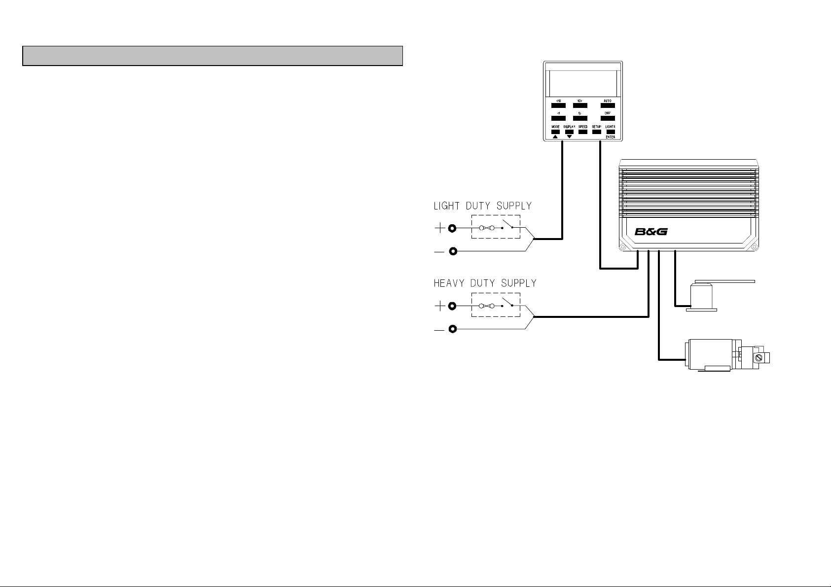
SWITCHING THE PILOT ON
Your Network PILOT will usually have two circuit breakers,
one which supplies the Network PILOT Display and Network
Instruments (light duty supply) and the other that supplies the
Ram Drive or Pump Unit (heavy duty supply). Both must be
switched on before the autopilot will operate.
3
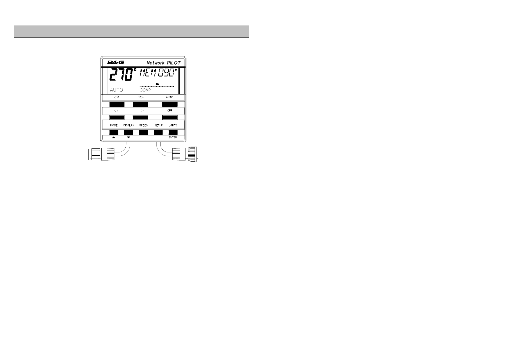
NETWORK PILOT DISPLAY UNIT
The back-lit Liquid Crystal Display (LCD) shows the following
information.
LARGE DIGITS (top left) - When the Network PILOT is
disengaged the digits show compass heading. When the
autopilot is engaged the digits show the course the autopilot
is steering.
TEXT WINDOW (top right) - When visible, information and
messages can be displayed.
RUDDER ANGLE BAR DISPLAY - Analogue indication of
rudder position. First 6 divisions 10 resolution, then 2 of 20,
then 4 of 50. Maximum rudder angle ±300.MODE LEGENDS
(bottom row) - Text legends appear depending upon the
steering mode and if the autopilot is engaged or disengaged.
The six large keys are the main control keys of the Network
PILOT.
AUTO Engages the autopilot in any mode, also used to
execute certain steering functions.
OFF Disengages the autopilot and returns the boat to
manual steering.
<10,<1 PORT course change buttons for increments of
100 or 10.
10>,1> STARBOARD course change buttons for
increments of 100 or 10.
The five keys in the lowest row of the Network PILOT Display
provide additional functions as follows:
MODE Changes the steering mode. Steer to COMPass,
Steer to VANE (requires Network WIND), Steer
to NAV (requires NMEA input from position fixer
e.g. GPS, LORAN, DECCA.
DISPLAY Changes the information displayed in the text
window of the LCD, this depends on mode
selected.
SPEED Selects speed information displayed in the text
window of the LCD.
SETUP Enables autopilot parameters and alarms to be
set and enabled.
LIGHTS Three levels of illumination and off.
4
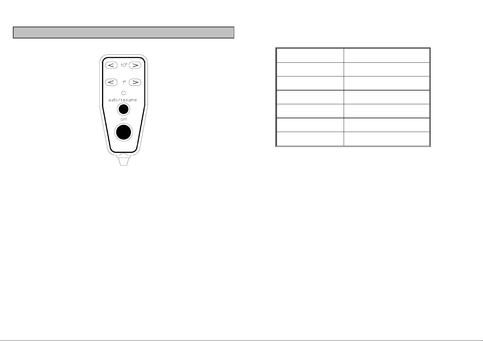
NETWORK PILOT HAND-HELD CONTROLLER
The Handheld Controller provides remote control of the
Network PILOT. The six keys give the same control functions
as the six large keys on the Network PILOT display unit.
< 100 > 10
< 10 > 1
auto/resume PILOT engage and return to course
off PILOT disengage
0
course change
0
course change
Standby
Pilot Engaged
Course Change
Commissioning
Compass Cal.
Fault
Man Overboard
_ _ _
________
____ ____
_ _ _ _ _
_ ___ _ __
__ __ __
_ _ _ _ _ _
In the centre of the handheld controller is an LED that will
flash the coded sequences shown in the table above.
5

JOYSTICK (OPTIONAL TYPE 2 SYSTEM ONLY)
The joystick allows direct control of the rudder via the
autopilot computer unit for quick and responsive steering.
There are two modes of joystick operation available to the
helmsman, giving different steering control, (see USING THE
SETUP KEY, JOYSTICK STEERING to select the modes).
The button at the top of the joystick enables the Network
PILOT to be engaged and disengaged in joystick steering
mode.
1. NORMAL STEERING
The rudder moves in the direction of the joystick, when the
joystick is returned to the central position the rudder
movement stops. The greater the movement of the joystick
the faster the response of the rudder.
2. PROPORTIONAL STEERING
The position of the rudder imitates the position of the joystick,
when the joystick is returned to the central position the
rudder returns to its initial position.
ENGAGING THE PILOT IN JOYSTICK MODE
• Turn the steering wheel so the rudder is in the midships
position. See NOTE.
• Press the button on the top of the joystick to engage the
PILOT.
• Move the joystick to port or starboard to move the
rudder.
When the PILOT is engaged in joystick mode the text area of
the Network PILOT LCD will show JOYSTCK, the rudder
angle bar display will show rudder position, and heading (in
degrees) will be shown on the large LCD digits.
NOTE : When the PILOT is engaged using the joystick
button the rudder position (at the moment of engaging) will
be the central position of the joystick. It is advisable to
ensure that this is the midships position of the rudder.
By steering the vessel on to a straight and steady course
before engaging the autopilot, any external influences on the
steering will be counteracted, e.g. wind and tide. However
this is only true as long as you maintain the same course.
DISENGAGING THE PILOT FROM JOYSTICK MODE
EITHER:
• Press the joystick button.
OR
• Press the red OFF key on any Network PILOT display.
When the PILOT is disengaged from joystick mode the
Network PILOT LCD will return to the normal STDBY display.
IMPORTANT NOTE
The Network PILOT red OFF key can be used to disengage
the autopilot and resume manual steering from any mode.
6
BASIC PRINCIPLES OF OPERATION
When the Network PILOT is powered on it will be in Standby
mode, STDBY indicated on the Liquid Crystal Display (LCD).
The LCD also shows the Current Heading in digits, the
rudder position on a bar display and the operating mode,
initially Compass COMP. To steer the boat automatically,
turn the boat onto the desired heading and engage the
autopilot by pressing the AUTO key on any Network PILOT
display or Hand-held Controller. If manual steering is
required press the red OFF key and the autopilot returns to
standby, STDBY.
When the autopilot is steering, course changes are made by
multiple presses of the <10 or 10> keys and the <1 or 1>
keys on any Network PILOT display or Hand-held Controller.
WARNING
When the autopilot is engaged manual steering is not
possible. To resume manual steering the red OFF key
must be pressed on any Network PILOT Display or Handheld Controller. It is the responsibility of the skipper to
brief all crew members about this procedure.
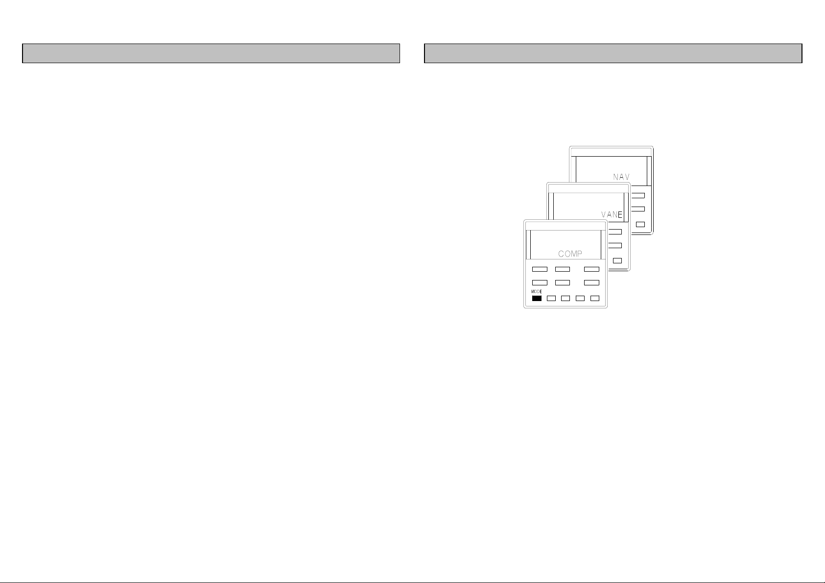
MODE SELECTION
The MODE key enables the steering mode to be changed.
There are three steering modes, however selection is
dependant upon your boat type and Network System.
• COMP Steer to Compass. The basic mode for all
autopilot systems on power and sail boats. When
switched on the Network PILOT is always in this
mode.
• VANE Steer to Wind. Only selectable on sail boats that
have a Network System containing a Network
WIND unit.
• NAV Steer to Navigational data. Selectable with all
autopilot systems that are linked to an NMEA
position fixer e.g. GPS, Decca, Loran.
Depending upon the mode extra operations and displays are
available, refer to the sections on VANE and NAV.
7

STEER TO COMP MODE
8
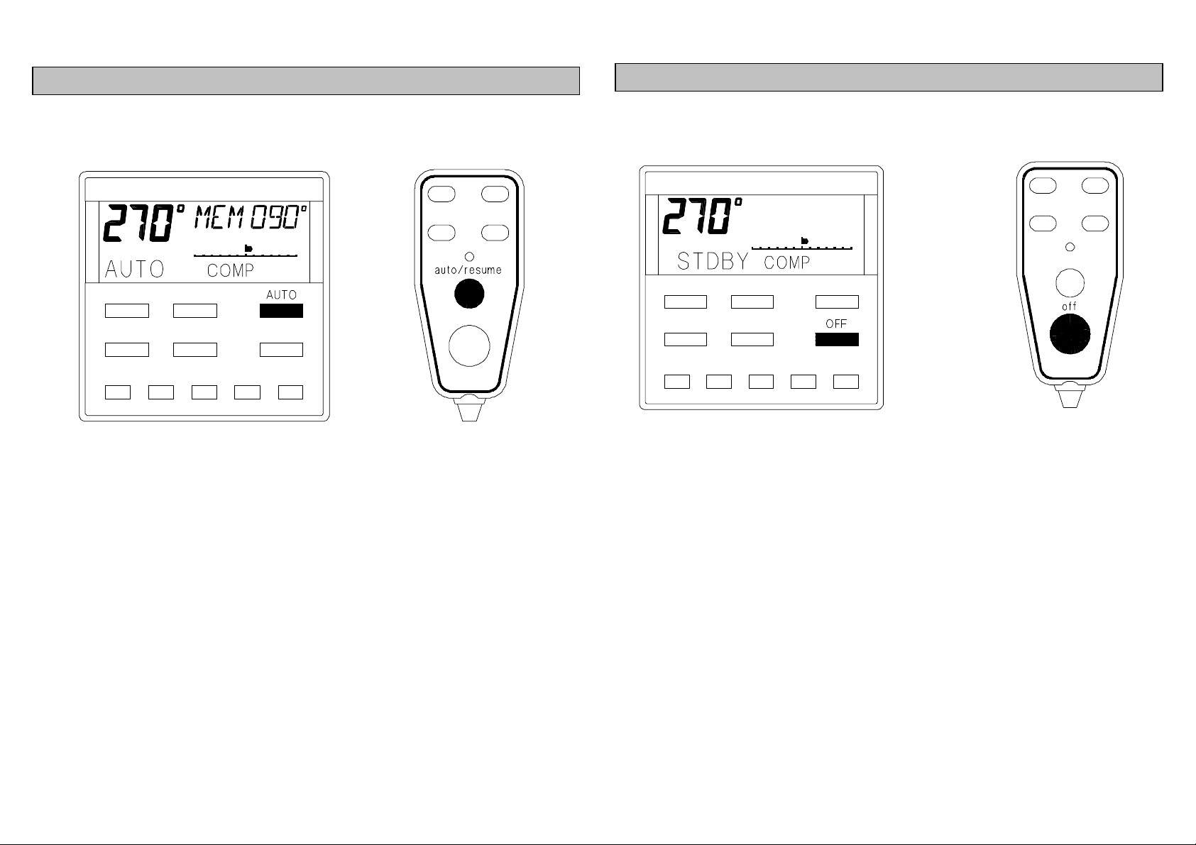
ENGAGING PILOT ON CURRENT COURSE
• If necessary, press the MODE key to select COMPass.
• Press the AUTO key once to engage the autopilot on the
current course.
NOTE
The Network PILOT has a Course Memory, the previous
autopilot course is stored in it when the autopilot is
disengaged for future use. The previous autopilot course is
displayed for 4 seconds in the LCD text area, this is recalled
from the autopilot Course Memory.
DISENGAGING THE PILOT
• Press the OFF key to disengage the autopilot.
• The previous autopilot course is MEMorised.
NOTE
The previous autopilot course is always stored in the course
memory when the autopilot is disengaged.
9
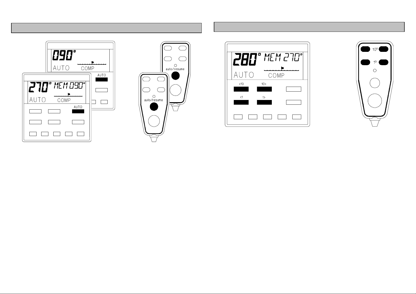
ENGAGING PILOT ON PREVIOUS COURSE
• Press the AUTO key twice within 4 seconds to engage
the autopilot on the previous MEMorised course.
NOTE
In this example the current course is 2700, the previous
autopilot course was 0900, displayed in the LCD text window.
The autopilot will steer the boat on to 0900 as soon as the
AUTO key is pressed the second time.
CHANGING PILOT COURSE
• Press <10 or <1 to alter course to port in 100 or 10
increments.
• Press 10> or 1> to alter course to starboard in 100 or 10
increments.
• Multiple presses of the keys are added together to give
the required course change, e.g. for 200 to port press <10
twice, for 110 to starboard press 10> then 1>.
• The previous autopilot course is MEMorised and
displayed in the LCD text window.
10
key twice within 4 seconds to return to
orised course shown in the LCD text
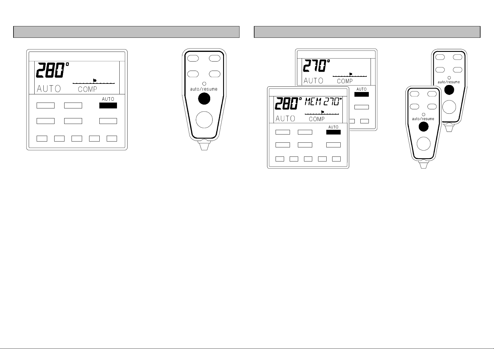
MEMORISING THE NEW COURSE
• Press AUTO key once to store the new course in the
autopilot course memory.
NOTE
It is suggested that this carried out after every permanent
course change, i.e. not when you have just steered around
an obstacle.
RETURNING TO THE PREVIOUS COURSE
• Press the AUTO
the previous MEM
window.
NOTE
If you have used the course memory after every permanent
course change then the autopilot will steer the boat back on
to your last autopilot course. If not, the autopilot will steer on
to the last course that was memorised. Check that the
MEMorised course in the LCD text window is the one that
you want.
11
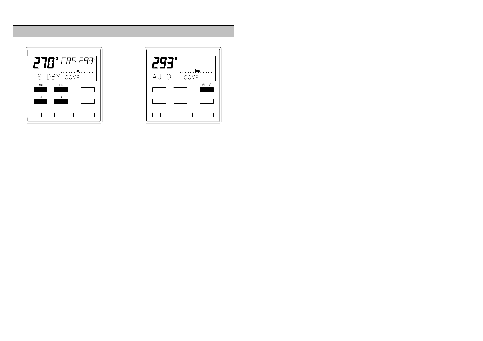
PRESETTING THE PILOT COURSE
• The autopilot has to be disengaged in STDBY to preset
the course.
• Use <10,<1,10>,1> keys to alter the course
displayed in the LCD text window.
• Press AUTO to engage the autopilot and automatically
steer on to the preset course.
12
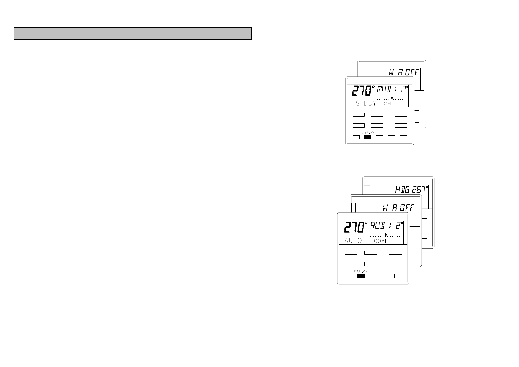
USING THE DISPLAY KEY IN COMP MODE
Press the DISPLAY key to cycle through additional autopilot
and navigational information, displayed in the LCD text
window.
• RUD Rudder Angle - Digits indicated rudder angle in
degrees to port <, or to starboard >.
• W A Watch Alarm - Will indicate OFF or the time in
minutes and seconds until the alarm sounds.
• HDG Heading - This is the actual compass heading in
degrees. The large digits indicate the autopilot
course.
PILOT IN STDBY
PILOT IN AUTO
13

STEER TO NAV MODE
14

NAV MODE - ADDITIONAL INFORMATION
The position fixer has a compatible NMEA 0183 (v1.5)
up and connected in accordance with the
The signal and noise levels are within the manufacturers
The waypoint have been entered correctly, and the
If using waypoints in a Route or Sail (cruise) Plan, they
When the autopilot in engaged in NAV mode it will steer a
course using waypoint data from a position fixer programmed
with the waypoint positions.
The position fixer can be any GPS (Global Positioning
System), DECCA or LORAN-C receiver, with a compatible
NMEA 0183 (v1.5) interface.
POSITION FIXER ERRORS
It is important to remember that when the autopilot is steering
to NAV, any erratic or positional errors generated by the
position fixer due to poor reception, bad satellite constellation
or radio beacon chain transitions, will be transferred to the
autopilot via the NMEA interface. This could cause steering
inaccuracy so always maintain a log and positional plot on a
current chart. Also ensure that the autopilot course will steer
you clear of any obstacles, taking into account tides.
Before using your position fixer to steer to NAV, check the
following:
•
interface, setmanufacturers instructions.
• It is switched on and has the correct current position.
•
recommended levels.
•
waypoint arrival alarm switched on (if it has one).
•
are entered correctly and the route is enabled.
15
 Loading...