

Page 1
L8542279
Rev. 11/01/00
AUTOMATISMI PER CANCELLI
LO.R1W/2W/1E/2E/1A/2A
1) Cancellazione della memoria: dare tensione mantenendo premuto il pulsante sulla ricevente, finchè non si accende il led
arancio e aspettare che si spenga.
2) La memoria può contenere 6 telecomandi a codice fisso con codici diversi, quando è completa lo segnala con la
sequenza luminosa Rosso-Verde-Arancione ripetuta per due volte.
3) Per effettuare l’autoapprendimento dei trasmettitori, tenere premuto per 4-5 secondi il pulsante del ricevitore, la segnalazione di 5 lampeggi verdi indica l’ingresso in modalità programmazione, autoapprendimento codice trasmettitore:
a) Si accende il led rosso (rosso = primo canale).
b) Se si preme un pulsante del radiocomando questo verrà associato al primo canale, se non si preme nulla dopo 5
secondi la programmazione prosegue.
c) Si accende il led verde (verde = secondo canale, solo con LO.R2W/2E/2A).
d) Se si preme un pulsante questo verrà associato al secondo canale, se non si preme nulla dopo 5 secondi la programmazione prosegue.
e) Si accende il led arancione (arancione = entrambi i canali, solo con LO.R2W/2E/2A).
f) Se si preme un pulsante questo verrà associato ad entrambi i canali, se non si preme nulla dopo 5 secondi la programmazione prosegue. Dopo il punto f) il ricevitore esce dalla modalità autoapprendimento trasmettitori, questo viene segnalato dalla sequenza di 5 lampeggi verdi.
Modalità Tempi
La programmazione di questa funzione è necessaria solo se l’utente vuole impostare il relè come temporizzato a 1 minuto
oppure bistabile. Il modo di funzionamento di default è impostato impulsivo a 1 sec.
Per impostare la programmazione dei tempi relè per il primo trasmettitore procedere come segue:
a) Premere il pulsante del ricevitore fino a quando non si vedrà visualizzata la sequenza di 5 lampeggi rossi (il tasto deve
essere premuto per circa 12 secondi).
b) Il led rosso esegue un lampeggio che indica l’entrata per la programmazione dei tempi per il 1° ch. Ad ogni pressione di
un tasto qualsiasi del tx il led esegue in maniera ciclica 1, 2 o 3 lampeggi e poi riparte con 1, 2, 3 lampeggi. Ad ogni diversa
modalità di lampeggio corrisponde una diversa modalità di eccitazione del relè, come riportato nella tabella A.
Per memorizzare la modalità desiderata premere un tasto qualsiasi del tx fino ad ottenere il lampeggio corrispondente alla
funzione scelta nella tabella quindi attendere 5 secondi, il programma proseguirà oltre automaticamente.
c) Il led verde esegue un lampeggio, questo indica l’entrata per la programmazione dei tempi per il 2° ch.
La procedura è analoga al punto b) (solo riferita al 2° ch.); proseguire con il punto (b) e poi passare direttamente al (d).
d) Dopo 5 secondi 5 lampeggi rossi indicano l’uscita in modalità di programmazione.
Tabella A
N. lampeggi
1
2
3
Modalità relè
Ecc. per 1 secondo
Ecc. per 1 minuto
ON / OFF
Consigli per l’utilizzo
Per non incorrere in eventuali funzionamenti anomali, si consiglia di non autoapprendere dei trasmettitori con i dip settati tutti
in on oppure tutti in off. Per avere buone portate si consiglia di installare l’antenna lontano da masse metalliche e di evitare il
posizionamento ravvicinato di più ricevitori.
Caratteristiche tecniche
Frequenza
Antenna
Alimentazione
Numero Tx
Portata
Canali
Contatto relè
Consumo a riposo
Consumo 1 ch. o 2 ch. eccitato
Consumo 1 ch. e 2 ch. eccitati
Quando il ricevitore è in funzione il lampeggio della luce rossa indica la
presenza di disturbi radio.
Il ponticello jumper nella scheda serve per scegliere la tensione di alimentazione.
Jumper chiuso = 12Vac/dc
Jumper aperto = 24Vac/dc
LO.R1W/2W
433.92MHz
Accordata
12-24Vac/dc
6
50-150 metri
Da 1 a 2
1A, 24Vdc
8mA
37mA
51mA
LO.R1/2A
306MHz
Accordata
12-24Vac/dc
6
50-150 metri
Da 1 a 2
1A, 24Vdc
8mA
37mA
51mA
LO.R1/2E
30.875MHz
Accordata
12-24Vac/dc
6
50-150 metri
Da 1 a 2
1A, 24Vdc
10mA
42mA
53mA
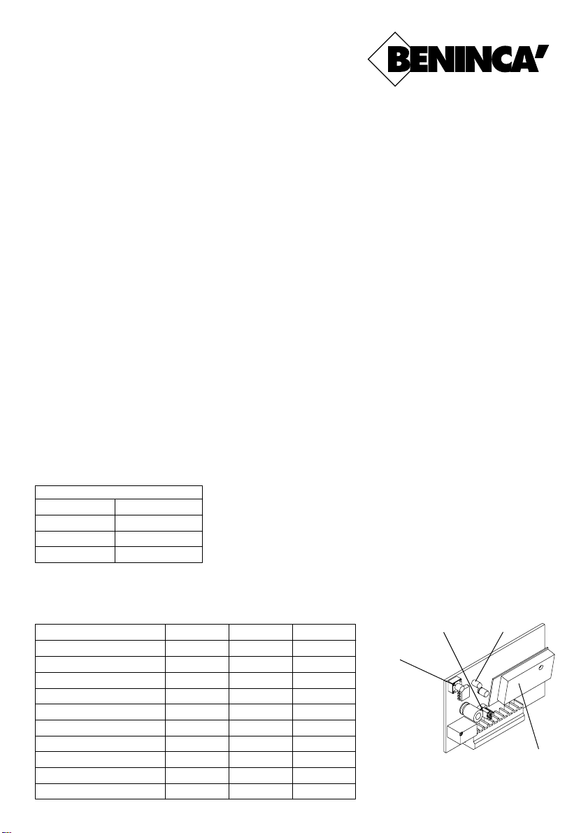
Tasto
programmazione
1,2 Contatto
1° canale N.A.
3,4 Contatto
2° canale N.A.
5 Alimentazione
12/24Vca/dc
negativo
6 Alimentazione
12/24Vca/dc
positivo
Jumper
1
7,8 Non utilizzato
9 Calza antenna
10 Antenna
Led
10
Modulo radio
®
Page 2
LO.R1W/2W/1E/2E/1A/2A
1) To erase memory: power the unit keeping the key pressed until the orange led switches on and wait till it switches off.
2) The memory can include 6 fixed code remote controls with different codes. Full memory is indicated by the light
sequence Red - Green - Orange, which is repeated twice.
3) To carry out the programming, keep the key pressed for 4-5 seconds; 5 flashes of green light will indicate that the
programming mode has been entered. Proceed as described hereunder:
a) The red Led switches on (red = first channel).
b) If a remote control key is pressed, this will be matched to the first channel. If it is not pressed, after 5 seconds the
programming procedure carries on.
c) The green led switches on (green = second channel, only with LO.R2W/2E/2A).
d) If a remote control key is pressed, this will be matched to the second channel. If no keys are pressed, after 5
seconds the programming procedure carries on.
e) The orange led switches on (orange = both channels, only with LO.R2W/2E/2A).
f) If a remote control key is pressed, this will be matched to both channels, if no keys are pressed, after 5 seconds
the programming procedure carries on. After point f) the receiver exits the programming mode with 5 flashes of green
light.
Timing modes
Programming this function is necessary only if the user wants to set the relay as temporized 1 minute or bistable.
The default is set to impulsive 1 sec.
To set relay time programming for the first transmitter proceed as follows
a) Keep the programming key pressed until you see 5 flashes of red light (the key must be pressed for about 12
seconds).
b) The red led (first channel) flashes. When any key on the remote control is pressed, the led flashes 1, 2 or 3 times in
a cyclical way. Each different flashing mode corresponds to a different mode of relay triggering, as indicated in the
following table A.
To store the desired mode in memory, press the any key on the transmitter until the corresponding flashing is obtained. Then wait for 5 seconds and the programme will carry on automatically.
c) The green led (second channel) flashes, the procedure is similar to point b) but is referred to the second channel.
Proceed with point b) and then jump directly to point d).
d) After 5 seconds, 5 red flashes indicate that the programming mode has been exited.
Table A
No. of flashes
1
2
3
Relay mode
Triggering for 1 sec.
Triggering for 1 min.
ON / OFF
Warnings and advice
Not to face any eventual malfunctioning, it is strictly recommended not to run self-learning procedure of transmitters
having all dip-switches set in ON or OFF position. In order to have a good range, it is better to install the antenna far from
obstacles and metal structures and to avoid a too close positioning of more than one receiver.
Technical features
Frequency
Antenna
Power supply
No. of Tx
Range
Channels
Relay contact
Consumption when in stand-by
Consump. with one relay trigg.
Consump. with both relays trigg.
433.92MHz
Tuned
12-24Vac/dc
6
50-150 metres
From 1 to 2
1A, 24Vdc
8mA
37mA
51mA
When the receiver is operating, the red flashing light indicates that radio
interference be present.
The jumper on the electronic board is used to set the power supply.
Jumper closed: 12Vac/dc
Jumper open: 24Vac/dc
LO.R1W/2W
LO.R1/2A
306MHz
Tuned
12-24Vac/dc
6
50-150 metres
From 1 to 2
1A, 24Vdc
8mA
37mA
51mA
LO.R1/2E
30.875MHz
Tuned
12-24Vac/dc
6
50-150 metres
From 1 to 2
1A, 24Vdc
10mA
42mA
53mA
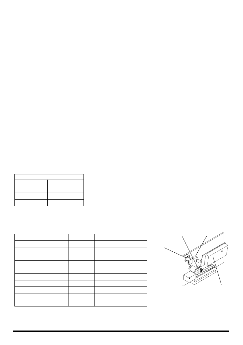
Programming
key
1,2 1st channel
N.O. contact
3,4 2nd channel
N.O. contact
5 Power supply
12/24Vca/dc
negative
6 Power supply
12/24Vca/dc
positive
Jumper
1
7,8 Not in use
9 Antenna bride
10 Antenna
Led
10
Radio module
AUTOMATISMI BENINCÀ Srl - Via Capitello, 45 - 36066 Sandrigo (VI) - Tel. 0444 751030 r .a. - Fax 0444 759728
 Loading...