

Page 1
L8542176
Rev. 04/05/02
AUTOMAZIONE A TRAINO PER PORTE SEZIONALI RESIDENZIALI
PULLING AUTOMATIC SYSTEM FOR RESIDENTIAL SECTIONAL DOORS
AUTOMATISCHE SCHLEPPVORRICHTUNG FÜR SEKTIONALE TÜREN
AUTOMATISME À ENTRAÎNEMENT POUR PORTES SECTIONNELLES RESIDENTIALES
AUTOMATIZACIÓN DE ARRASTRE PARA PUERTAS SECCIONALES RESIDENTIALES
POCIĄGNIK AUTOMATYCZNY DO BRAM SEKCYJNYCH
KTE
Libro istruzioni e catalogo ricambi
Operating instructions and spare parts catalogue
Betriebsanleitung und Ersatzteilliste
Livret d’instructions et catalogue des pieces de rechange
Libro de instrucciones y catálogo de recambios
Książeczka z instrukcjami i katalog części wymiennych
UNIONE NAZIONALE COSTRUTTORI
AUTOMATISMI PER CANCELLI, PORTE,
SERRANDE ED AFFINI
Page 2
3
Dichiarazione CE di conformità per macchine
(Direttiva 89/392 CE, Allegato II, parte B)
Divieto di messa in servizio
Fabbricante: Automatismi Benincà SpA
Indirizzo: Via Capitello, 45 - 36066 Sandrigo (VI) - Italia
Dichiara che: lʼautomazione a traino per porte sezionali modello KTE.
• è costruito per essere incorporato in una macchina o per essere assemblato con altri macchinari per costituire una macchina
considerata dalla Direttiva 89/392 CE, come modicata;
• non è dunque conforme in tutti i punti alle disposizioni di questa Direttiva;
• è conforme alle condizioni delle seguenti altre Direttive CE:
Direttiva bassa tensione 73/23/CEE, 93/68/CEE.
Direttiva compatibilità elettromagnetica 89/336/CEE, 93/68/CEE.
e che:
• sono state applicate le seguenti (parti/clausole di) norme armonizzate:
EN 61000-6-1, EN 61000-6-3, EN 60335-1.
e inoltre dichiara che non è consentito mettere in servizio il macchinario no a che la macchina in cui sarà incorporato o di cui diverrà
componente sia stata identicata e ne sia stata dichiarata la conformità alle condizioni della Direttiva 89/392 CE e alla legislazione
nazionale che la traspone, vale a dire no a che il macchinario di cui alla presente dichiarazione non formi un complesso unico con
la macchina nale.
Benincà Luigi, Responsabile legale.
Sandrigo, 10/10/2005.
Declaration by the manufacturer
(Directive 89/392/EEC, Art. 4.2 and Annex II, sub B)
Divieto di messa in servizio
Manufacturer: Automatismi Benincà SpA.
Address: Via Capitello, 45 - 36066 Sandrigo (VI) - Italia
Herewith declares that: the pulling automatic system for sectional doors model KTE.
• is intended to be incorpored into machinery or to be assembled with other machinery to constitute machinery covered by Directive
89/392 EEC, as amended;
• does therefore not in every respect comply with the provisions of this Directive;
• does comply with the provisions of the following other EEC Directives:
Direttiva bassa tensione 73/23/CEE, 93/68/CEE.
Direttiva compatibilità elettromagnetica 89/336/CEE, 93/68/CEE.
and that:
• the following (parts/clauses of) harmonized standards have been applied:
EN 61000-6-1, EN 61000-6-3, EN 60335-1.
and furthermore declares that it is not allowed to put the machinery into service until the machinery into which it is to be incorporated
or of which it is to be a component has been found and declared to be in conformity with the provisions of Directive 89/392/EEC and
with national implementing legislation, i.e. as a whole, including the machinery referred to in this declaration.
Benincà Luigi, Responsabile legale.
Sandrigo, 10/10/2005.
2
Page 3

Herstellerklärung
(gemäß EG-Richtlinie 89/392/EWG, Artikel 4.2 und Anhang II, sub B.)
Verbot der Inbetriebnahme
Hersteller: Automatismi Benincà SpA.
Adresse: Via Capitello, 45 - 36066 Sandrigo (VI) - Italia
erklärt hiermit, daß: Automatische Schleppvorrichtung für sektionale Türen KTE.
• vorgesehen ist zum Einbau in eine Maschine oder mit anderen Maschinen zu einer Maschine im Sinne der Richtlinie 89/392/
EWG, inklusive deren Änderunge, zusammengefügt werden soll;
• aus diesem Grunde nicht in allen Teilen den Bestimmungen dieser Richtlinie entspricht;
• den Bestimmungen der folgenden anderen EG-Richtlinien entspricht:
Direttiva bassa tensione 73/23/CEE, 93/68/CEE.
Direttiva compatibilità elettromagnetica 89/336/CEE, 93/68/CEE.
und daß:
• folgende harmonisierte Normen (oder Teile/Klauseln hieraus) zur Anwendung gelangten:
EN 61000-6-1, EN 61000-6-3, EN 60335-1.
und erklärt des weiteren daß die Inbetriebnahme solange untersagt ist, bis die Maschine oder Anlage, in welche diese Maschine
eingebaut wird oder von welcher sie eine Komponente dasteilt, als Ganzes (d.h. inklusive der Maschine, für welche diese Erklärung
ausgesteilt wurde) den Bestimmungen der Richtlinie 89/392/EWG sowie dem entsprechenden nationalen Reschtserlaß zur Umsetzung
der Richtlinie in nationales Recht entspricht, und die entsprechende Konformitätserklärung ausgestellt ist.
Benincà Luigi, Responsabile legale.
Sandrigo, 10/10/2005.
Declaration du fabricant
(Directive 89/392/CEE, Article 4.2 et Annex II, Chapitre B)
Interdiction de mise en service
Fabricant: Automatismi Benincà SpA.
Adresse: Via Capitello, 45 - 36066 Sandrigo (VI) - Italia
Déclaire ci-apres que: lʼautomatisme à entraînement pour portes sectionnelles KTE.
• est prévue pour être incorporée dans une machine ou être assemblée avec dʼautres machines pour consituer une machine couverte
par la directive 89/392/CEE, modiée;
• nʼest donc pas conforme en tout point aux dispositions de cette directive;
• est conforme aux dispositions des directives CEE suivantes:
Direttiva bassa tensione 73/23/CEE, 93/68/CEE.
Direttiva compatibilità elettromagnetica 89/336/CEE, 93/68/CEE.
et que:
• les (parties/paragraphes) suivants des normes harmonisées ont été appliquées:
EN 61000-6-1, EN 61000-6-3, EN 60335-1.
et déclare par ailleurs quʼil est interdit de mettre la machine en service avant que la machine dans laquelle elle sera incorporée ou
dont elle constitue une parte ait été considerée et declarée conforme aux dispositions de la Directive 89/392/CEE et aux législations
nationales la transposant, cʼest-à-dire formant un ensemble incluant la machine concernée par la présente déclaration.
Benincà Luigi, Responsabile legale.
Sandrigo, 10/10/2005.
3
Page 4

5
Declaración CE de conformidad para maquinas
(Directiva 89/392 CE, Apartado II, parte B)
Prohibición de puesta en servicio
Fabricante: Automatismi Benincà SpA.
Dirección: Via Capitello, 45 - 36066 Sandrigo (VI) - Italy
Declara que: la automatización de arrastre para puertas plegables KTE.
• está construída para ser incorporada en una máquina o para ser ensamblada con otras maquinarias para construir una máquina
considerada por la Directiva 89/392 CE, como modicada;
• no es, por consiguiente, conforme en todos los puntos a la posiciones de esta Directiva;
• es conforme a las condiciones de las siguientes otras Directivas CE:
Directiva de la baja tensión 73/23/CEE, 93/68/CEE.
Directiva de compatibilidad electromagnética 89/336/CEE, 93/68/CEE
y que
• han sido aplicadas las siguientes (partes/claúsulas de) normas armonizadas:
EN 61000-6-1, EN 61000-6-3, EN 60335-1.
además declara que no ha permitido poner en servicio la maquinaria hasta que la máquina en la cual será incorporada o de la cual
resultará componente esté identicada y no sea declarada la conformidad a las condiciones de la Directiva 89/392 CE y a la legislación
nacional que le corresponda, vale decir, hasta que la maquinaria correspondiente a la presente declaración no forme un conjunto único
con la máquina nal.
Benincà Luigi, Responsable legal.
Sandrigo, 10/10/2005.
Deklaracja UE o zgodności z normami dla maszyn
(Wytyczna 89/392 UE, Załącznik II, Część B)
Zakaz użytkowania
Producent: Automatismi Benincà SpA
Adres: Via Capitello, 45 - 36066 Sandrigo (VI) - Italia
Oświadcza że: Automatyzm do bram sekcyjnych model KTE
• został opracowany z myślą o wbudowaniu go do maszyny lub zmontowania z innymi urządzeniami w celu skonstruowania maszyny
uznanej przez Wytyczną 89/392 UE, za zmodykowaną;
• nie jest więc zgodny we wszystkich punktach z Wytyczną;
• jest natomiast zgodny z wymogami innych, poniżej wyszczególnionych, Wytycznych UE:
Wytyczna o niskim napięciu 73/23/EWG i 93/68/EWG
Wytyczna o zdolności współdziałania elektromagnetycznego 89/336/EWG, 93/68/EWG.
i że:
• zastosowane zostały następujące normy (ich klauzule/części) standard:
EN 61000-6-1, EN 61000-6-3, EN 60335-1.
ponadto oświadcza, że zabronione jest stosowanie automatyzmu do czasu kiedy maszyna, do której ma być wbudowany lub stanowić
jej element składowy, nie uzyska świadectwa identykacyjnego oraz świadectwa orzekającego jej zgodność z wymogami Wytycznej
89/392 UE oraz z przepisami obowiązującymi w kraju sprowadzającym urządzenie, a więc do czasu kiedy automatyzm stanowiący
przedmiot niniejszego oświadczenia nie stanie się częścią składową urządzenia gotowego.
Benincà Luigi, Radca prawny
Sandrigo, 10/10/2005.
4
Page 5
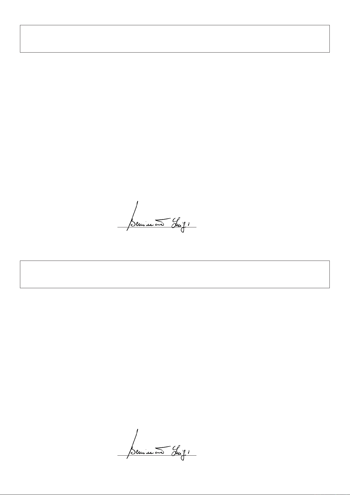
La porta deve aprirsi e chiudersi tirando e spingendo orizzon-
talmente sul bordo superiore.
It has to be possible to open and close the door by pulling
and pushing horizontally its top edge.
Das Tor muß zu öffnen und zu schließen sein, indem man es an
seinem Oberrand zieht und schiebt.
La porte devra pouvoir être ouverte et fermée en tirant et
en poussant horizontalement sur son bord supérieur.
La puerta debe abrirse y cerrarse tirando y empujando horizontalmente sobre el borde superior.
Brama musi się otwierać i zamykać poprzez poziome pociąganie i
popychanie górnej krawędzi.
Fig.1
min. 40mm
Dati tecnici
Alimentazione
Assorbimento
Velocità di trazione
Forza trazione/spinta
Lunghezza totale:
Altezza max. porta:
Peso gruppo motore
Peso totale:
Riferimento targhetta sull’azionamento
See operation plate
Siehe Schildchen auf der Motor-Gruppe
Technical data
Feed
Absorbed rating
Drive speed
Drive/thrust force
Total length:
Max. door height:
Power unit weight
Total weight:
Technische Daten Donnees technique
Speisung
Aufnahme
Zuggeschwindigkeit
Zugkraft/Schubkraft
Gesamtlänge:
Max. Torhöhe:
Gewicht der Motoreinheit
Gesamtgewicht:
Alimentation
Absorption
Vitesse de traction
Force traction/poussée
Longueur totale:
Hauteur max. porte:
Poids groupe moteur
Poids totale:
Voir la plaque sur le motoréducteur
Referencia tarjeta sobre el accionamiento
Tabliczka ze wskazaniami funkcjonowania
Datos técnicos
Alimentación
Absorción
Velocidad de tracción
Fuerza tracción/empuje
Longitud total:
Altura máx. de puerta:
Peso grupo motor
Peso total:
Dane techniczne
Zasilanie
Pobór mocy
Prędkość ciągnięcia
Siła ciągnięcia/pchania
Długość całkowita:
Wysokość max bramy:
Ciężar zepołu silniko-wego
Ciężar całkowity:
KTE
230Vac
80mA
6,5 / 5,2 m/1'
800N
3,38m
2,5m
5,6kg
11,2kg
Fig.2
5
Page 6
7
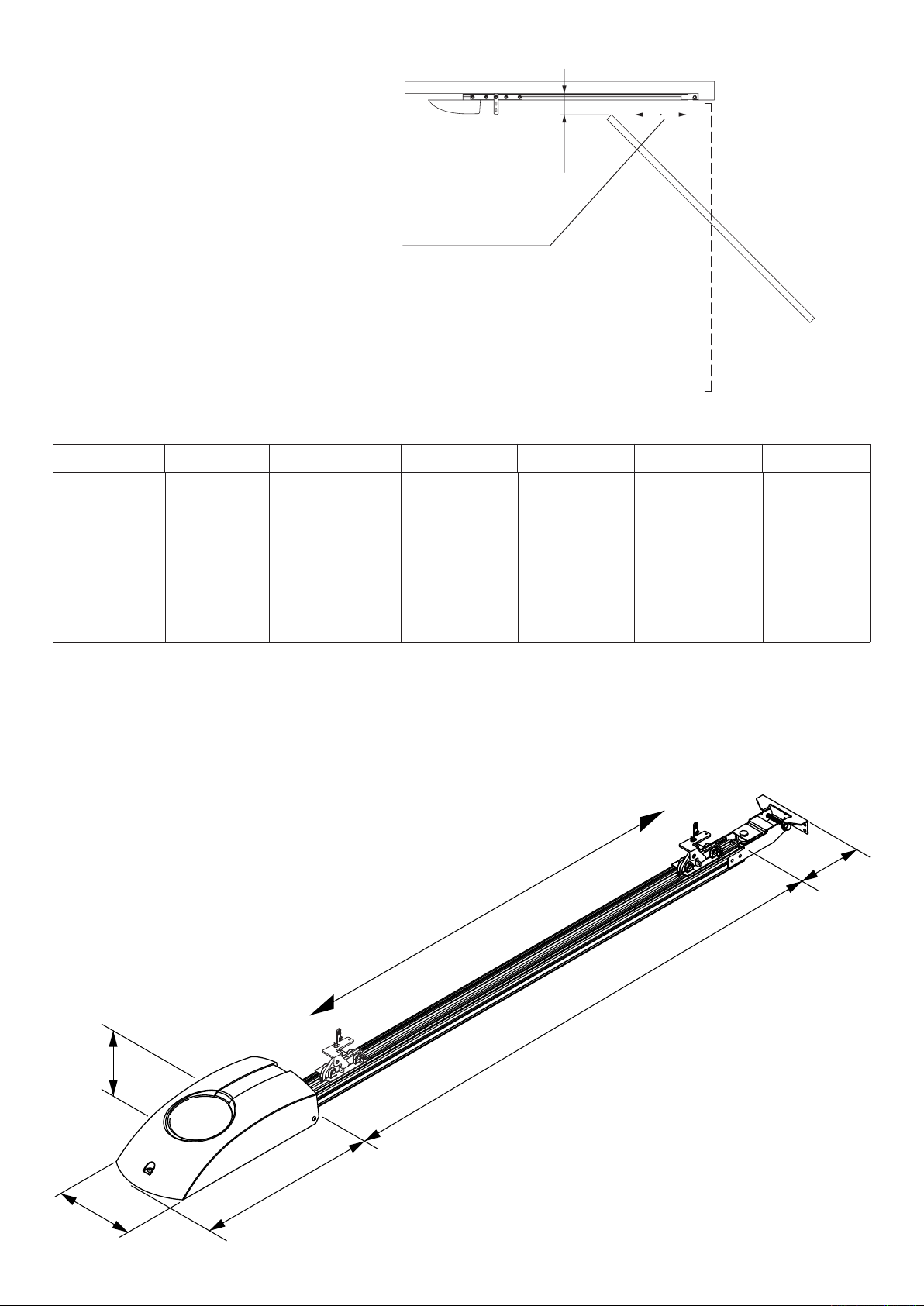
B
P
Fig.3
D2
Fig.4
D1
Viti M6x14.
Screws M6x14.
Schrauben M6x14.
Vis M6x14.
Tornillos M6x14.
Śruby M6x14.
Fig.5
6
Page 7
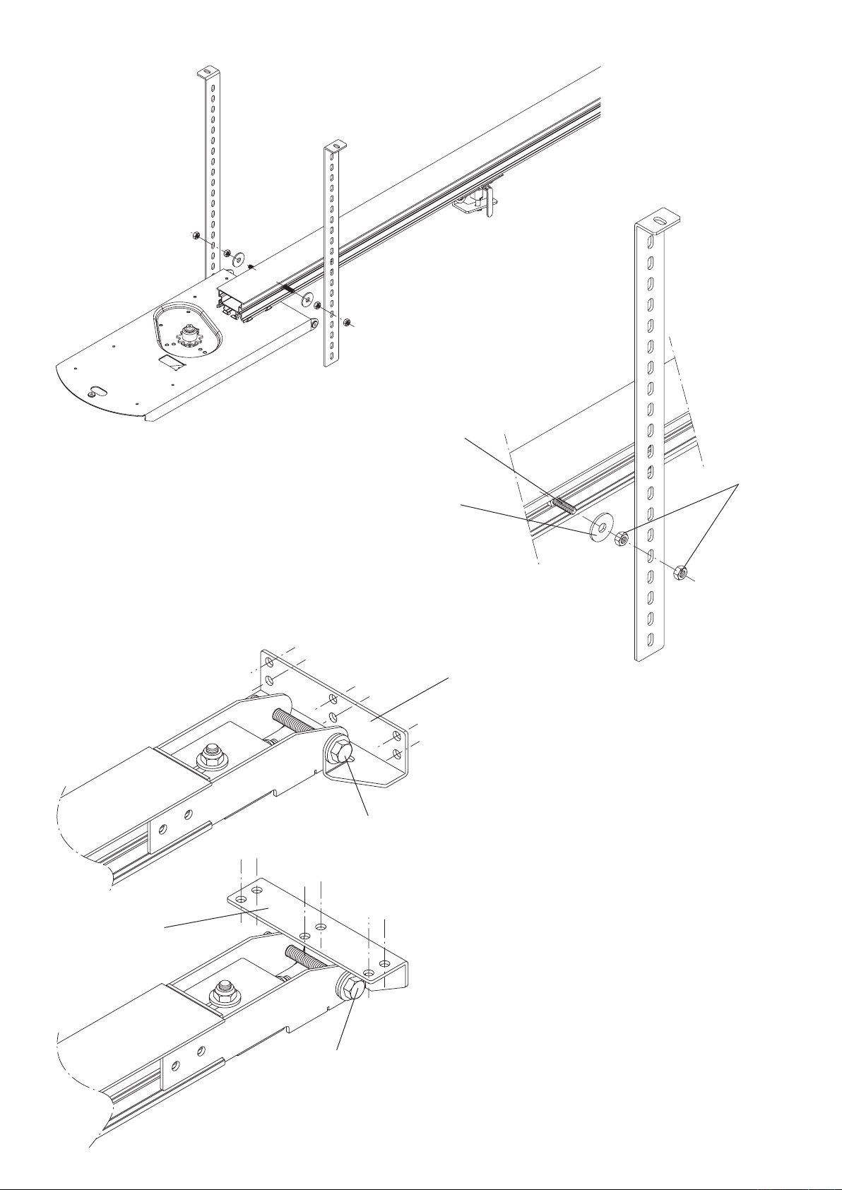
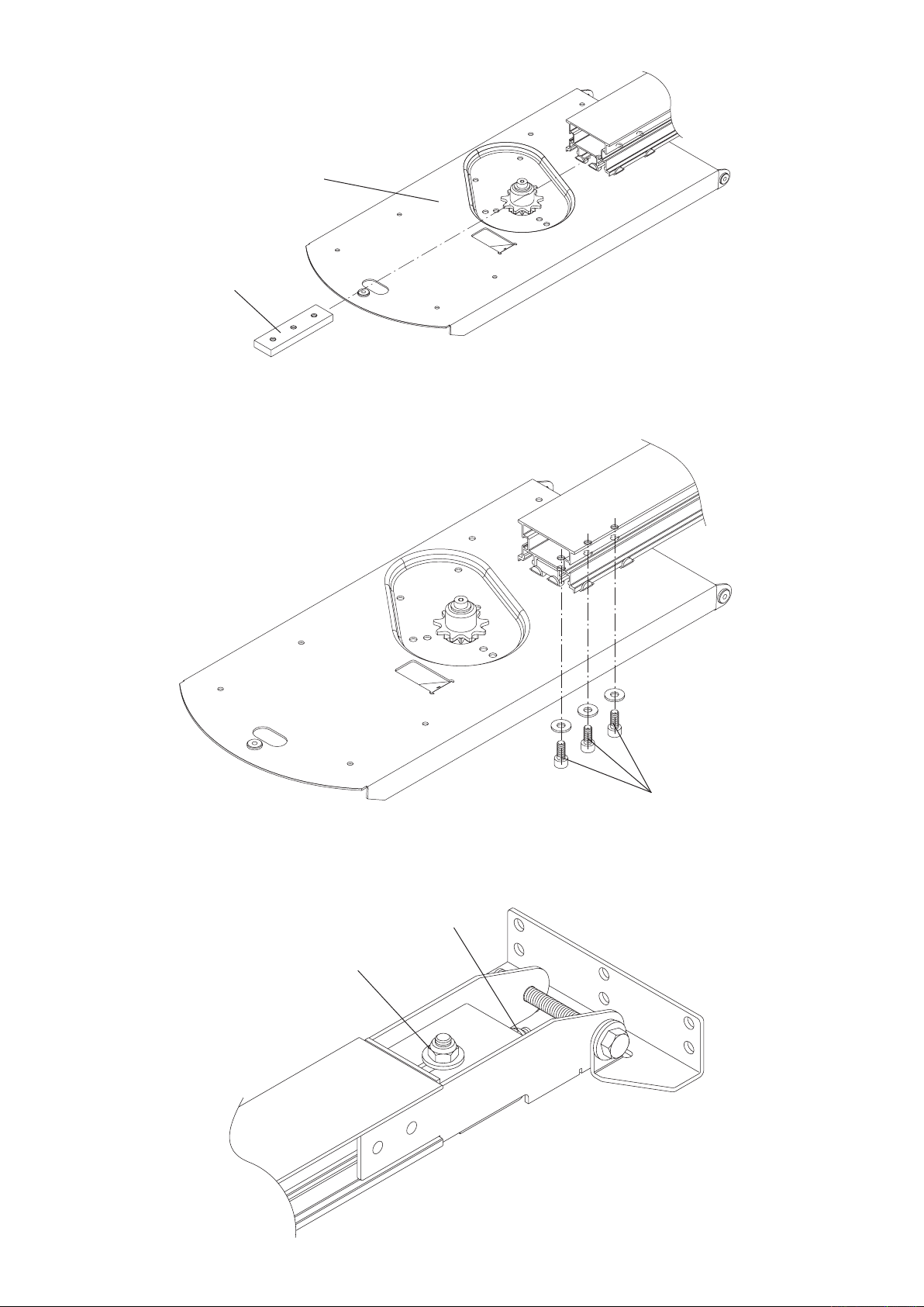
Fig.6
Vite M6x20 UNI 5739.
Screw M6x20 UNI 5739.
Schraube M6x20 UNI 5739.
Vis M6x20 UNI 5739.
Tornillo M6x20 UNI 5739.
Śruba M6x20 UNI 5739.
Rosetta 8x24x2.
Washer 8x24x2.
Unterlegscheibe 8x24x2.
Rondelle 8x24x2.
Arandela 8x24x2.
Podkładka 8x24x2.
Fig.7
Dado M6.
Nut M6.
Mutter M6.
Ecrou M6.
Tuerca M6.
Nakrętka M6.
S
Fissaggio a muro.
Wall fixing.
Befestigung an der Mauer.
Fixation murale.
Fijación a la pared.
Przymocowanie do ściany
Vite M8x80 UNI 5739.
Screw M8x80 UNI 5739.
Schraube M8x80 UNI 5739.
Vis M8x80 UNI 5739.
Tornillo M8x80 UNI 5739.
Śruba M8x80 UNI 5739.
S
Fissaggio a soffitto.
Fixing to ceiling.
Befestigung an der Decke.
Fixation au plafond.
Fijación al techo.
Przymocowanie do sutu
Vite M8x80 UNI 5739.
Screw M8x80 UNI 5739.
Schraube M8x80 UNI 5739.
Vis M8x80 UNI 5739.
Tornillo M8x80 UNI 5739.
Śruba M8x80 UNI 5739.
Fig.8
7
Page 8
8
9
A
S
Vite M6x20 UNI 5739.
Screw M6x20 UNI 5739.
Schraube M6x20 UNI 5739.
Vis M6x20 UNI 5739.
Tornillo M6x20 UNI 5739.
Śruba M6x20 UNI 5739.
Fig.9
Fig.10
S
V
Finecorsa apre.
Open limit switch.
Endschalter zum Öffnen.
Fin de course ouvre.
Final de carrera abre.
Wyłącznik krańcowy otwierania
Finecorsa chiude.
Close limit switch.
Endschalter zum Schließen.
Fin de course ferme.
Final de carrera cierra.
Wyłącznik krańcowy zamykania
S
V
9819009
Page 9

Fig.11
F
Blocca.
Block.
Sperrung.
Blocage.
Bloquea.
Blokuje
Cavo di acciaio.
Steel cable.
Stahlkabel.
Corde en acier.
Cable de acero.
Linka stalowa
Rosetta 9x24 UNI 6593.
Washer 9x24 UNI 6593.
Scheibe 9x24 UNI 6593.
Rondelle 9x24 UNI 6593.
Arandela 9x24 UNI 6593.
Podkładka 9x24 UNI 6593
Rosetta per M8 DIN 6798E.
Washer M8 DIN 6798E.
Scheibe M8 DIN 6798E.
Rondelle M8 DIN 6798E.
Arandela para M8 DIN 6798E.
Podkładka dla M8 DIN 6798E
Guaina.
Sheath.
Hülse.
Gaine.
Funda .
Osłona
Capocorda.
Cable terminal.
Kabelverbinder.
Extrémité de la corde.
Terminal del cable.
Końcówka przewodu
Registro.
Register.
Regulierung.
Réglage.
Reglaje.
Śruba regulacyjna
Blocca.
Block.
Sperrung.
Blocage.
Bloquea
Blokuje.
Fig.12
6,5m/1'
Morsetto.
Clamp.
Klammer.
Étau.
Perrillo.
Zacisk
5,2m/1'
Staffa.
Support.
Stütze.
Support.
Soporte.
Zaczep
Maniglia con piastra.
Handle with plate.
Handgriff mit Platte.
Manette avec plaque.
Manilla con placa.
Uchwyt z płytą
Vite M8x10 UNI 5739.
Screw M8x10 UNI 5739.
Schraube M8x10 UNI 5739.
Vis M8x10 UNI 5739.
Tornillo M8x10 UNI 5739.
Śruba M8x10 UNI 5739
Sblocca.
Unblock.
Freigabe.
Déblocage.
Desbloquea.
Odblokowanie
Kit sblocco a filo art. AU.MS25.
Wire release Art. AU.MS25.
Freigabe über Draht, AU.MS25.
Déblocage à fil art. AU.MS25.
Kit de desbloqueo por cable art. AU.MS25.
Zestaw odblokowania art. AU.MS25
9
Page 10

11
Fissare il braccio sul filo superiore della porta.
Fix the arm to the top edge of the door.
Arm an der oberen Kante des Tores befestigen
Fixer le bras sur l’arête supérieure de la porte.
Fijar el brazo en la arista superior de la puerta.
Przymocować ramię do górnej krawędzi bramy
Rotaia.
Rail.
Schiene.
Morceau de rail.
Guía.
Szyna
Braccio per porte a contrappesi art. AU.C25.
Overhead doors with balanceweights: special arm art. AU.C25.
Kipptor mit Gegengewichten: Sonderarm, Teil AU.C25.
Portes basculantes à contrepoids: bras spécial art. AU.C25.
Brazo para puerta de contrapesos art. AU.C25.
Ramię dla bram z przeciwwagą art. AU.C25
A porta chiusa lasciare 2 ÷ 3 cm.
Keep a distance of 2 ÷ 3 cm when the door is closed.
Wenn die Tür geschlossen ist, lassen 2 ÷ 3 cm.
Il faut lasser 2 ÷ 3 cm quand la porte est ouvert.
Cuando la puerta ésta cerrada, hay que haber 2 ÷ 3 cm.
Podczas zamkniętej bramy pozostawić 2 ÷ 3 cm.
Pattino.
Sliding plate.
Platte.
Plaque.
Patín.
Ślizgacz
Regolare
Adjust
Regulieren
Régler
Regulación
Regulowanie
Vite M6x35 UNI 5931
Screw M6x35 UNI 5931
Schraube M6x35 UNI 5931
Vis M6x35 UNI 5931
Tornillo M6x35 UNI 5931
Śruba M6x35 UNI 5931
Mettere a piombo il braccio.
Level the arm.
Arm lotrecht stellen.
Mettre à plomb le bras.
Aplomar bien el brazo.
Ustawić ramię w pozycji pionowej
Fig.13
10
Page 11

Introduzione
Ci congratuliamo con Voi per aver scelto il motoriduttore KTE.
Tutti gli articoli della vasta gamma Benincà sono il frutto di una ventennale esperienza nel settore degli automatismi e di una continua ricerca di nuovi materiali e di tecnologie all’avanguardia.
Proprio per questo, oggi siamo in grado di offrire dei prodotti estremamente affidabili che, grazie alla loro
potenza, efficacia e durata, soddisfano pienamente le esigenze dell’utente finale. Tutti i nostri prodotti sono
coperti da garanzia. Inoltre, una polizza R. C. prodotti stipulata con primaria compagnia assicurativa copre
eventuali danni a cose o persone causati da difetti di fabbricazione.
1. Notizie generali
L’automatismo è concepito per motorizzare porte sezionali; per essere applicato su porte basculanti necessita
di uno speciale braccio di attacco (art. AU.C25).
In ogni caso dovranno essere assolte le seguenti condizioni:
- la distanza tra il punto più alto della porta ed il soffitto deve essere almeno 40mm (fig.1);
- la porta deve potersi aprire e chiudere tirando e spingendo orizzontalmente sul suo bordo superiore
(fig.1);
- le manovre manuali devono risultare dolci e regolari.
2. Assemblaggio attuatore
a) Infilare la piastrina P nel profilo di alluminio fino a far collimare i fori con quelli della piastra di base B
(Fig.3).
b) Serrare il profilo di alluminio alla piastra di base mediante le tre viti M6x14 interponendo le rosette a fascia
larga (Fig.4).
c) Tensionare leggermente la catena avvitando il dado D1 (Fig.5).
N.B.: Una tensione troppo elevata è deleteria per l’automatismo e lo rende rumoroso.
d) Serrare forte il dado D2 (Fig.5).
e) Predisporre le staffe di attacco al soffitto preferibilmente vicino al motore (Fig.6). Per il fissaggio vedere
Fig.7.
f) Ancoraggio delle staffe di attacco al soffitto con il profilo di guida (Fig.7).
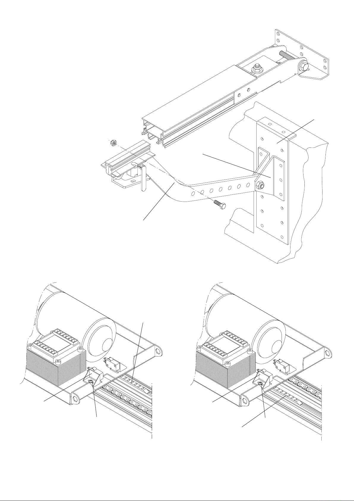
g) Ancorare la staffa “S” al muro o al soffitto mediante rivetti o viti e tasselli. Ancorare il profilo alla staffa S
con la vite a testa esagonale M8x80 ed il dado autobloccante (Fig.8).
h) Collegare l’asta di trascinamento A al pattino di trascinamento mediante la vite a testa esagonale M6x20
e dado autobloccante, evitando di bloccare l’asta stessa. Regolare l’altezza della staffa S in modo che, a
porta chiusa, l’asta A sia in posizione pressoché verticale (Fig.9).
3. Regolazione del finecorsa
Arrestare la porta circa 2cm prima della totale chiusura ed inserire la piastrina nella catena a filo della lamiera
come in fig.10. Effettuare la regolazione millimetrica allentando la vite V e traslando il supporto micro S.
Ripetere l’operazione in apertura.
4. Regolazione della velocità
Spostare il fast-on F per ottenere una delle due velocità (Fig.11):
• 5,2m/1', consigliata per porte basculanti;
• 6,5m/1' per porte sezionali.
5. Manovra manuale dall’esterno
Nelle porte sezionali è possibile sbloccare l’automazione anche dall’esterno utilizzando l’art. AU.MS25
(Fig.12).
6. Montaggio su porte basculanti
Basculante a contrappesi (Fig.13): le basculanti a contrappesi necessitano dell’apposito braccio art. AU.C25.
Unici accorgimenti per il montaggio di quest’ultimo sono:
• fissare il braccio sul filo superiore della porta
• mettere a piombo il braccio stesso.
ATTENZIONE
La polizza RC prodotti, che risponde di eventuali danni a cose o persone causati da difetti di fabbricazione,
richiede l’utilizzo di accessori originali Benincà.
11
Page 12

13
Introduction
Thank you for choosing our KTE ratiomotor.
All items in the wide Benincà production range are the result of twenty-years’ experience in the automatism
sector and of continuous research for new materials and advanced technologies.
We are, therefore, in the position to offer highly reliable products that due to their power, effectiveness and
useful life, fully satisfy the final user’s requirements.
All our products are covered by warranty.
Possible injury to people or accidents caused by defects in construction are covered by a civil liability policy
drawn up with one of the major insurance companies.
1. General information
The system has been studied to motorize sectional doors.
To be applied onto balancing doors, a special fitting arm is required (item AU.C25).
In any case, following conditions will have to be observed:
- the distance between the door highest point and the ceiling must be at least 40mm (fig. 1).
- it has to be possible to open and close the door by pulling and pushing horizontally its top edge (fig.1).
- manual moves must be smooth and regular.
2. Assembling the actuator
a) Introduce the plate P in the aluminium profile until the holes of the plate correspond to the holes of the base
plate B (Fig.3).
b) Fasten the plate P to the base plate by using the three screws M6x14. Provide for large washers between
the plate and the screws (Fig.4).
c) Slightly tension the chain by tightening the nut D1 (Fig.5).
N.B.: An excessively high tension might cause serious damage to the system and renders it noisy.
d) Firmly tighten the nut D2 (Fig.5).
e) Place the fixing brackets to ceiling preferably near the motor (Fig.6). For fastening, see Fig.7.
f) To anchor the ceiling fixing brackets to the guide profile (Fig.7).
g) Anchor the bracket “S” to wall or ceiling by using rivets or screws and dowels. Anchor the profile to bracket
S with the hexagonal head screws M8x80 and the self-locking nut (Fig.8).
h) Connect the dragging rod A to the dragging slide by using the hexagonal head screw M6x20 and self-lock-
ing nut. Avoid blocking the rod. Adjust the bracket S height so as to ensure that, when the door is closed,
the rod A is almost vertically positioned (Fig.9).
3. Adjusting the limit switch
Stop the door at about 2cm before its complete closure. Introduce the plate in the chain placed along the
sheet metal, as shown in the fig.10. Carry out the fine adjustment of the limit switch by loosening the screw
V and moving the micro S support. Repeat this operation in the opening phase.
4. Adjustment of speeds
Move the fast-on switch F to obtain one of the two speeds (Fig.11):
• 5,2m/1' is recommended for balancing doors;
• 6,5m/1' for sectional doors.
5. Manual operation from outside
In sectional doors, the system can be released also from outside by using item AU.MS25 (Fig.12).
6. Assembling onto balancing doors
Overhead door with balanceweights (fig.13): these doors need the special arm art. AU.C25.
In order to assemble it make sure that:
• the arm is fixed to the top edge of the door.
• the arm is levelled.
CAUTION
The civil liability policy, which covers possible injuries to people or accidents caused by defects in construction, requires to use original Benincà accessories.
12
Page 13

Einleitung
Wir danken Ihnen dafür, daß Sie sich für das KTE Steuergehäuse entschieden haben.
Alle Produkte der umfangreichen Benincà Produktion sind das Ergebnis der zwanzigjährigen Erfahrungen im Bereich
der Automation und der ständigen Erforschung von neuen Materialien und fortgeschrittenen Technologien.
Aus diesem Grund sind wir heute in der Lage, zuverlässige Produkte anzubieten, die, dank ihren Stärke, Wirksamkeit
und Haltbarkeit, der Anforderungen des Endverbrauchers völlig gerecht werden.
Alle Produkte sind durch Garantie gedeckt.
Eventuelle Personen- oder Sachschäden, die durch Fertigungsfehler verursacht werden können, werden durch
eine der wichtigsten Versicherungsgesellschaften gedeckt.
1. Allgemeine Information
Die Automatik bedient über einen Motor sektionale Türen; um an Schwenktüren installiert zu werden, muss ein
spezieller Arm angeschlossen werden (art. AU.C25).
Jedenfalls müssen folgende Bedingungen erfüllt werden:
- Der Abstand zwischen der höchsten Stelle des Tores und der Decke muß wenigstens 40mm sein (Bild 1).
- das Tor muß zu öffnen und zu schließen sein, indem man es an seinem Oberrand zieht und schiebt (Bild 1).
- Die Handgriffe müssen sanft und regelmäßig sein.
2. Betätigungsgerät zusammenbauen
a) Plättchen P in das Alu-Profil einsetzen, bis die Löcher mit denen der Basisplatte B übereinstimmen (Abb.3).
b) Das Aluprofil an die Basisplatte mit den Schrauben M6x14 festschrauben und dazwischen die breiten Scheiben
legen (Abb.4).
c) Kette leicht über die Mutter D1 spannen (Abb.5).
N.B.: Eine zu hohe Spannung beeinträchtigt die Automatik und macht sie geräuschvoll.
d) Mutter D2 richtig festziehen (Abb.5).
e) Bügel zur Befestigung an die Decke wenn möglich in der Nähe des Motors (Abb.6). Zur Befestigung siehe Ab-
bildung 7.
f) Verankerung der Bügel zur Befestigung an die Decke mit dem Führungsprofil (Abb.7).
g) Den Bügel „S“ an die Mauer oder an die Decke mit den Nieten oder den Schrauben und Dübeln verankern. Das
Profil am Bügel S mit der sechskantigen Schraube M8x80 und der selbstsichernden Mutter verankern (Abb.8).
h) Die Mitnehmerstange A an den Mitnehmerschuh mit der sechskantigen Schraube M6x20 und der selbstsichernden
Mutter verbinden, jedoch vermeiden dass die Stange selbst blockiert wird. Die Höhe des Bügels S so einstellen,
dass bei geschlossener Tür die Stange A praktisch vertikal liegt (Abb.9).
3. Endschalter einstellen
Die Tür 2cm vor der vollkommen geschlossenen Position anhalten und das Plättchen in die Kette am Blechrand,
wie in der Abb.10 gezeigt, stecken. Die millimetergenaue Einstellung vornehmen; dazu die Schraube V lockern und
die Halterung des Mikroschalters S verschieben. Dasselbe in der offenen Position vornehmen.
4. Geschwindigkeit einstellen
Den Fast-On F versetzen, um eine der zwei Geschwindigkeiten einzustellen (Abb.11):
• 5,2m/1' ist für Schwenktüren zu empfehlen;
• 6,5m/1' sind für sektionale Türen zu empfehlen.
5. Manuelle Betätigung von Außen
Bei den sektionalen Türen kann die Automatik auch von außen mit Hilfe des Art. AU.MS25 freigesetzt werden
(Abb.12).
6. Montage an Schwenktüren
Kipptor mit Gegengewichten (Bild 13): Kipptore mit Gegengewichten erfordern den Sonderarm Teil. AU.C25.
Bei seiner Anbringung ist nur zu beachten:
• Arm an der oberen Kante des Tores befestigen,
• Arm lotrecht stellen.
BITTE BEACHTEN
Die Versicherung deckt nur Personen- oder Sachschäden, die durch Fertigungsfehler verursacht werden und gilt
nur bei Einsatz von Benincà Original-Ersatzteilen.
13
Page 14

15
Introduction
Nous ne pouvons que féliciter d’avoir porté votre choix sur le moto-réducteur KTE.
Vingt années d’expérience dans le secteur des automatismes ainsi que dans le recherche de nouveaux
matériaux et technologies de pointe, nous ont permis de développer tous les nombreux articles de la gamme
Benincà. Pour ces raisons, nous sommes en mesure de proposer des produits extrémement fiables et qui
grâce à leurs puissances, performances et longévité, répondent aux exigences des utilisateurs.
Tous nos produits sont garantis.
En plus, une police d’assurance responsabilité civile garantie la couverture d’éventuels sinistres à personnes
ou objects causés par les défauts de fabrication.
1. Notice générales
L’automatisme est conçu pour motoriser des portes sectionnelles; pour pouvoir l’appliquer sur des portes
basculantes il nécessite d’un bras de fixation spécial (art. AU.C25).
Dans tous les cas, les conditions suivantes devront être prises:
- la distance entre le point le plus haut de la porte et le plafond devra être au minimum de 40mm (fig.1)
- la porte devra pouvoir être ouverte et fermée en tirant et en poussant horizontalement sur son bord supé-
rieur (fig.1).
- les opérations manuelles doivent résulter douces et règulières.
2. Assemblage actionneur
a) Introduire la plaque P dans le profil en aluminium jusqu’à ce que les trous coïncident avec ceux de la plaque
de base B (Fig.3).
b) Serrer le profil en aluminium à la plaque de base au moyen des trois vis M6x14 en intercalant les rondelles
à bande large (Fig.4).
c) Tendre légèrement la chaîne en serrant l’écrou D1 (Fig.5).
N.B.: Une tension trop élevée risque d'endommager l'automatisme et de le rendre bruyant.
d) Serrer fort l’écrou D2 (Fig.5).
e) Mettre en place les brides de fixation au plafond de préférence près du moteur (Fig.6). Pour la fixation voir
la figure 7.
f) Ancrage des brides de fixation au plafond avec le profil de guidage (Fig.7).
g) Ancrer la bride "S" au mur ou au plafond au moyen des rivets ou des vis tamponnées. Ancrer le profil à la
bride S avec la vis à tête hexagonale M8x80 et l’écrou autoserreur (Fig.8).
h) Assembler la tige d’entraînement A au patin d’entraînement au moyen de la vis à tête hexagonale M6x20 et
de l’écrou autoserreur, en évitant de bloquer la tige elle-même. Régler la hauteur de la bride S de manière
à ce que, la porte étant fermée, la tige A soit en position pratiquement verticale (Fig.9).
3. Réglage du fin de course
Arrêter la porte 2cm environ avant sa fermeture totale et introduire la platine dans la chaîne au ras de la tôle
comme indiqué dans la fig.10. Effectuer le réglage millimétrique en desserrant la vis V et en déplaçant par
translation le support du micro S. Répéter l’opération en ouverture.
4. Réglage de la vitesse
Déplacer le faston F pour obtenir une des deux vitesses (Fig.11):
• 5,2m/1', conseillée pour les portes basculantes;
• 6,5m/1' pour les portes sectionnelles.
5. Manœuvre manuelle de l’extérieur
Dans les portes sectionnelles, l’automatisme peut être déverrouillé également de l’extérieur à l’aide de l’art.
AU.MS25 (Fig.12).
6. Montages sur les portes basculantes
Portes basculantes à contrepoids (fig.13): les portes basculantes à contrepoids nécessitent un bras approprié
art. AU.C25. Les seuls moyens pour le montage de ce dernier sont:
• fixer le bras sur l’arête supérieure de la porte;
• mettre à plomb le bras même.
ATTENTION
Pour que la police d’assurance R.C. réponde à d’eventuels sinistres causés à choses ou personnes, en cas
de défauts de fabrication, il faut que soient utilisés des accessoires Benincà.
14
Page 15

Introducción
Nos congratulamos con vd. por haber elegido el motorreductor KTE.
Todos los artículos de la vasta gama Benincà son el fruto de una veinteañal experiencia en el sector de los
automatismos y de una continua búsqueda de nuevos materiales y de tecnología de vanguardia.
Es precisamente por ello el que hoy nos encontramos en situación de ofrecer productos extremadamente fiables que, gracias a su potencia, eficacia y duración, satisfacen plenamente las exigencias del usuario final.
Todos nuestros productos están garantizados.
Además, una póliza R.C. productos, contratada con una compañía de seguros de primera línea, cubre eventuales daños a cosas o personas causados por defectos de fabricación.
1. Noticias generales
El automatismo está diseñado para motorizar puertas plegables; para aplicarlo en puertas basculantes requiere un brazo especial de conexión (art. AU.C25).
En cualquier caso deberán tenerse en cuenta las condiciones siguientes:
- la distancia entre el punto más alto de la puerta y el techo debe ser de al menos 40mm. (fig.1);
- la puerta deberá poder abrir o cerrarse tirando o empujando horizontalmente sobre el borde superior
(fig.1);
- las maniobras manuales deben resultar suaves y regulares.
2. Montaje actuador
a) Introducir la plaqueta P en el perfil de aluminio hasta encarar los agujeros con los de la placa de base B
(Fig.3).
b) Sujetar el perfil de aluminio a la placa de base con los tres tornillos M6x14 poniendo las arandelas de franja
ancha (Fig.4).
c) Tensar ligeramente la cadena enroscando la tuerca D1 (Fig.5).
N.B.: Una tensión demasiado alta es perjudicial para el automatismo y lo hace ruidoso.
d) Apretar a fondo la tuerca D2 (Fig.5).
e) Predisponer los estribos de unión al techo, preferentemente cerca del motor (Fig.6). Para la fijación ver la
fig.7.
f) Anclaje de los estribos de unión al techo con el perfil de guía (Fig.7).
g) Anclar el estribo “S” a la pared o al techo con remaches o pernos de expansión. Anclar el perfil al estribo
S con el tornillo de cabeza hexagonal M8x80 y la tuerca autoblocante (Fig.8).
h) Conectar la barra de arrastre A con el patín de arrastre utilizando el tornillo de cabeza hexagonal M6x20
y la tuerca autoblocante, evitando bloquear la barra. Ajustar la altura del estribo S de manera que, con la
puerta cerrada, la barra A esté en posición casi vertical (Fig.9).
3. Ajuste del final de carrera
Detener la puerta unos 2cm antes del cierre total e introducir la placa en la cadena a ras de la plancha, como
mostrado en la fig.10. Efectuar el ajuste milimétrico aflojando el tornillo V y desplazando el soporte micro S.
Repetir la operación en apertura.
4. Ajuste de la velocidad
Desplazar el fast-on F para conseguir una de las dos velocidades (Fig.11):
• 5,2m/1', aconsejada para puertas basculantes;
• 6,5m/1' para puertas plegables.
5. Maniobra manual desde el exterior
En las puertas plegables es posible desbloquear la automatización también desde el exterior utilizando el
art. AU.MS25 (Fig.12).
6. Montajes en puertas basculantes
Las basculantes de contrapesos (fig.13) necesitan el correspondiente brazo art. AU.C25. Las únicas particularidades para este último montaje son:
• fijar el brazo sobre la arista superior de la puerta.
• aplomar bien dicho brazo.
ATENCION
La póliza RC productos, que responde de eventuales daños a personas o cosas causados por defectos de
fabricación, requiere la utilización de accesorios originales Benincà.
15
Page 16

17
Wprowadzenie
Gratulujemy Państwu wyboru siłownika KTE.
Wszystkie urządzenia naszej szerokiej gamy produktów są wynikiem dwudziestoletniego doświadczenia w sektorze automatyzacji bram
oraz stałego poszukiwania nowych rozwiązań w zakresie materiałów i awangardowej technologii.
Właśnie dzięki temu jesteśmy w stanie zaproponować Państwu produkty cieszące się wyjątkowym zaufaniem dzięki ich mocy, skuteczności
działania i trwałości – t.j. cechom, które zadowalają w pełni wymagania użytkownika.
Wszystkie nasze produkty posiadają gwarancję.
Ponadto została zawarta polisa ubezpieczeniowa z jednym ze znaczących towarzystw ubezpieczeniowych, która pokrywa koszty
ewentualnych szkód materialnych lub na rzecz osób, spowodowane błędami fabrycznymi.
1. Informacje ogólne
Automatyzm ten został opracowany z myślą o zmotoryzowaniu bram sekcyjnych; w celu zastosowania go do bram uchylnych wymagane
jest specjalne ramię zaczepowe (art. AU.C25).
W każdym razie spełnione muszą być spełnione następujące warunki:
- odległość pomiędzy najwyższym punktem bramy a sutem musi wynosić co najmniej 40 mm (rys.1);
- brama musi się otwierać i zamykać poprzez poziome pociąganie i popychanie górnej krawędzi (rys.1);
- ręczna obsługa bramy musi przebiegać w sposób łagodny i regularny.
2. Montaż siłownika
a) Wprowdzić płytkę P do kształtownika aluminiowego w taki sposób, żeby otwory pokrywały się z otworami płyty podstawy B (Rys.
3).
b) Przymocować kształtownik aluminiowy do płyty podstawy przy pomocy trzech śrub M6x14, podkładając podkładki z szerokimi
opaskami (Rys.4).
c) Naciągać lekko łańcuch poprzez dokręcenie nakrętki D1 (Rys.5).
Uwaga: nadmierne natężenie działa niszcząco na automatyzm i powoduje hałaśliwą pracę urządzenia.
d) Docisnąć mocno nakrętkę D2 (rys.5).
e) Przystawić do sutu zaczepy, najlepiej w pobliżu silnika (Rys.6). W celu ich umocowania zobacz Rys. 7.
f) Przymocować zaczepy do sutu wraz z prowadnicą (rys.7).
g) Przymocować do ściany lub sutu zaczep „S” za pomocą nitów lub śrub i klinów. Przymocować prowadnicę do zaczepu S za pomocą
śruby z łbem sześciokątnym M8x80 i nakrętki samozabezpieczającej (Rys.8)
h) Przyłączyć sztabę pociągającą A do prowadnika ciągnącego za pomocą śruby z łbem sześciokątnym M6x20 i samozabezpieczającej
nakrętki, uważając by nie zablokować sztaby. Uregulować wysokość zaczepu S w taki sposób, żeby przy bramie zamkniętej sztaba A
znajdowała się w pozycji prawie pionowej (rys.9).
3. Regulacja wyłącznika krańcowego
Zatrzymać bramę w pozycji około 2 cm przed pełnym zamknięciem i wprowadzić płytkę do metalowego łańcucha, tak jak to pokazano
na rys. 10. Ustalić regulację milimetrową poprzez poluzowanie śruby V i przemieszczając mikroobudowę S.
Powtórzyć tę samą operację w cyklu otwierania.
4. Regulacja szybkości
Ustawić przełącznik fast-on F w celu uzyskania jednej spośród dwu szybkości (rys.11):
• 5,2m/1’, zalecana dla bram uchylnych;
• 6,5m/1’ zalecana dla bram sekcyjnych.
5. Manewr ręczny od zewnątrz
W przypadku bram sekcyjnych możliwe jest odblokowanie automatyzmu również od zewnątrz, przy pomocy zestawu odblokowania
art. AU.MS25 (Fig.12).
6. Montowanie do bram uchylnych
Uchylne z przeciwwagą (rys.13): w przypadku bram uchylnych z przeciwwagą należy zamontować specjalne ramię art. AU.C25.
Dla zamontowania ramienia należy jedynie:
• przymocować ramię do górnej krawędzi bramy
• ustawić ramię w pozycji pionowej.
UWAGA
Towarzystwo ubezpieczeniowe wypłaca odszkodowanie z tytułu ewentualnych szkód poniesionych przez rzeczy lub osoby w wyniku
wad produkcyjnych, pod warunkiem stosowania originalnych części Benincà.
16
Page 17

Pos. Cod.
1
Denominazione - Description - Bezeichnung - Dénomination - Denominación - Opis
2
3
4
5
6
9686915
9686914
9686913
9686918
9686919
9686920
9686921
9686140
9686928
9686952
7
8
9
10
Tendicatena
Rotaia
Carro di trascinamento
Carter
Pignone
Trasformatore
Motore
Lampada
Centralina
Finecorsa assemblato
Tensor de cadena
Guía
Patín de tracción
Protección
Engranaje
Trasformador
Motor
Lámpara
Centralita
Final de carrera ensamb.
Chain tightener
Rail
Drive trolley
Guard
Gear
Transformer
Motor
Lamp
Electronic control card
Limit switch assembled
Kettenspanner
Schiene
Mitnehmerwagen
Gehäuse
Zahnrad
Trasformator
Motor
Lampe
Elektronische Deckel
Zusamm. Endschalter
Tendeur de châine
Rail
Chariot d’entraînement
Carter
Engrenage
Trasformateur
Moteur
Lampe
Fiche électronique
Fin de course assemblé
Napinacz acucha
Szyna
Wóek cigncy
Karter
Wa napdzajcy
Transformator
Silnik
Lampa
Centralka
Kracowy wycznik zmont.
17
Page 18

19
KTE
Libro istruzioni per l’utilizzatore
L
Tirare per ripristinare il funzionamento
automatico.
P
Tirare verso il basso per poter eseguire la manovra
manuale.
Norme di sicurezza
• Non sostare nella zona di movimento della porta.
• Non lasciare che i bambini giochino con i comandi o in prossimità delle ante.
• In caso di anomalie di funzionamento non tentare di riparare il guasto ma avvertire un tecnico specializzato.
Manovra manuale dall’interno
Per sbloccare l’automazione e procedere alla manovra manuale è sufficiente tirare il pomello P verso il basso.
Per tornare poi al funzionamento automatico spingere la levetta L verso la porta e dare un impulso di apertura
o chiusura all’automazione che si ripristinerà.
Se l’automazione si trova ad un’altezza da terra tale che la leva L non possa essere raggiunta agevolmente,
utilizzare un altro cordino con pomello.
Manutenzione
• Controllare periodicamente l’efficienza dello sblocco manuale di emergenza.
• Astenersi assolutamente dal tentativo di effettuare riparazioni, potreste incorrere in incidenti; per queste
operazioni contattare un tecnico specializzato.
• L’attuatore non richiede manutenzioni ordinarie, tuttavia è necessario verificare periodicamente l’efficienza
dei dispositivi di sicurezza e le altre parti dell’impianto che potrebbero creare pericoli in seguito ad usura.
Smaltimento
Qualora il prodotto venga posto fuori servizio, è necessario seguire le disposizioni legislative in vigore al momento per quanto riguarda lo smaltimento differenziato ed il riciclaggio dei vari componenti (metalli, plastiche, cavi
elettrici, ecc.); è consigliabile contattare il vostro installatore o una ditta specializzata ed abilitata allo scopo.
Attenzione
Tutti i prodotti Benincà sono coperti da polizza assicurativa che risponde di eventuali danni a cose o persone
causati da difetti di fabbricazione, richiede però la marcatura CE della ”macchina” e l’utilizzo di componenti
originali Benincà.
18
Page 19

User’s handbook
KTE
L
Pull to reset the automatic operating mode.
P
Pull downward to carry out the manual operation.
Safety rules
• Do not stand in the movement area of the door.
• Do not let children play with controls and near the door.
• Should operating faults occur, do not attempt to repair the fault but call a qualified technician.
Manual operation from the inside
To release the automatic system and proceed to the manual operation, it is sufficient to pull the knob P
downwards. To switch to the automatic mode again, push the level L towards the door and give an impulse
control for the opening and closing of the system.
If the height at which the system is fitted renders the level L difficult to reach, use another cord with knob.
Maintenance
• Every month check the good operation of the emergency manual release.
• It is mandatory not to carry out extraordinary maintenance or repairs as accidents may be caused. These
operations must be carried out by qualified personnel only.
• The operator is maintenance free but it is necessary to check periodically if the safety devices and t h e
other components of the automation system work properly. Wear and tear of some components could
cause dangers.
Waste disposal
If the product must be dismantled, it must be disposed according to regulations in force regarding the differentiated waste disposal and the recycling of components (metals, plastics, electric cables, etc..). For this
operation it is advisable to call your installer or a specialised company.
Warning
All Benincá products are covered by insurance policy for any possible damages to objects and persons
caused by construction faults under condition that the entire system be marked CE and only Benincá parts
be used.
19
Page 20

21
KTE
Handbuch für den Verbraucher
L
Ziehen, um den automatischen Betrieb
zurück zu setzen.
P
Nach unten ziehen, um den manuellen Vorgang
vornehmen zu können.
Sicherheitsvorschriften
• Nicht im Öffnungsbereich verweilen.
• Kinder nicht mit den Steuerungen oder in der Nähe des Tores spielen lassen.
• Bei Funktionsausfällen nicht versuchen, den Schaden selber zu beheben, sondern den Techniker rufen.
Manuelle Betätigung von Innen
Um die automatische Vorrichtung freizusetzen und sie manuell betätigen zu können, genügt es den Kugelgriff P nach unten zu ziehen. Um auf die automatische Bedienung zurückzuschalten, den Hebel L zur Tür
drücken und den Steuerbefehl zum Öffnen oder Schließen der automatischen Vorrichtung geben, die somit
auf automatisch zurückschaltet.
Falls die automatische Vorrichtung zu hoch installiert ist und vom Boden nicht leicht erreicht werden kann,
eine Schnur mit Kugelgriff verwenden.
Wartung
• Monatliche Kontrolle der manuellen Notentriegelung
• Es ist absolut untersagt, selbstständig Sonderwartung oder Reparaturen vorzunehmen, da Unfälle die Folge
sein können; wenden Sie sich an den Techniker.
• Der Antrieb braucht keine ordentliche Unterhaltung aber es ist periodisch notwendig die Leistungsfähigkeit
der Sicherheitsvorrichtungen und die andere Teile des Anlages zu prüfen. Sie könnten durch Abnutzung
Gefaht hervorbringen.
Entsorgung
Wird das Gerät außer Betrieb gesetzt, müssen die gültigen Gesetzesvorschriften zur differenzierten Entsorgung
und Wiederverwendung der Einzelkomponenten, wie Metall, Plastik, Elektrokabel, usw., beachtet werden.
Rufen Sie Ihren Installateur oder eine Entsorgungsfirma.
Achtung
Alle Produkte BENINCA’ wurden mit einem Versicherungsschein versehen, der alle eventuellen Schäden an
Dingen oder Personen abdeckt, die durch Herstellungsdefekte hervorgerufen wurden, vorausgesetzt, das
Gerät besitzt die Kennzeichnung EU und es wurden original BENINCA’ Einzelkomponenten verwendet.
20
Page 21

Manuel d’instructions pour l’utilisateur
KTE
L
Tirer pour restaurer le fonctionnement
automatique.
P
Tirer vers le bas pour pouvoir exécuter la manœuvre
manuelle.
Normes de sécurité
• Ne pas stationner dans la zone de mouvement de la porte.
• Ne laissez pas les enfants jouer avec les commandes ou à proximité de la porte.
• En cas d’anomalies de fonctionnement, n’essayez pas de réparer la panne mais contactez un tech-nicien
spécialisé.
Manœuvre manuelle de l’intérieur
Pour déverrouiller l’automatisme et effectuer la manœuvre manuelle il suffit de tirer le pommeau B vers le
bas. Pour retourner au fonctionnement automatique pousser le levier L vers la porte et donner une impulsion
d’ouverture ou de fermeture à l’automatisme qui se restaurera.
Si l’automatisme se trouve à une hauteur du sol telle que le levier L ne peut pas être atteint facilement, servez-vous d’un autre cordon muni d’un gland.
Maintenance
• Contrôler tous les mois le bon état du déverrouillage manuel d’urgence.
• Ne tenter aucune réparation ou intervention qui pourrait s’avérer dangereuse. Contactez impérativement
un technicien spécialisé pour ce type d’opération.
• L’operateur ne demande pas d’entretien particulier mais il faut vérifier périodiquement l’efficacité des dispo-
sitifs de sécurité ainsi que les autres points de l’installation qui pourraient créer des risques dû à l’usure.
Démolition
Au cas où le produit serait mis hors service, il est impératif de se conformer aux lois en vigueur pour ce qui
concerne l’élimination différenciée et le recyclage des différents composants (métaux, matières plastiques
câbles électriques, etc...) contactez votre installateur ou une firme spécialisée autorisée à cet effet.
Attention
Tous les produits Benincà sont couverts par une police d’assurance qui répond d’éventuels préjudices corporels ou matériels provoqués à cause de défauts de fabrication, mais qui requiert toutefois le marquage CE
de la “machine” et l’utilisation de pièces de rechange d’origine Benincà.
21
Page 22

23
KTE
Libro de instrucciones para el usuario
L
Tirar para restablecer el funcionamiento
automático.
P
Tirar hacia abajo para poder efectuar la maniobra
manual.
Mantenimiento
• Controlar periodicamente la eficiencia del desbloqueo manual de emergencia.
• Abstenerse absolutamente de intentar efectuar reparaciones, podrán incurrir en accidentes; para estas
operaciones contactar con un técnico especializado.
• El operador no requiere mantenimiento habitual, no obstante es necesario verificar periódicamente la efi-
ciencia de los dispositivos de seguridad y las otras partes de la instalación que pudiesen crear peligros a
causa del desgaste.
Normas de seguridad
• No pararse en la zona de movimiento de la puerta.
• No dejar que los niños jueguen con los mando o en proximidad de la puerta.
• En caso de anomalías de funcionamiento no intentar reparar la avería sino que avisar a un técnico espe-
cializado.
Maniobra manual desde el interior
Para desbloquear la automatización y proceder a la maniobra manual basta tirar de la empuñadura P hacia
abajo. Para volver seguidamente al funcionamiento automático, empujar la palanquita L hacia la puerta y dar
un impulso de apertura o cierre al automatismo el cual se restaurará.
Si la automatización se encuentra a una altura con respecto al suelo tal que no se logre alcanzar fácilmente
la palanca L, utilizar otro cordelillo con empuñadura.
Eliminación de aguas sucias
Cada vez que el producto esté fuera de servicio, es necesario seguir las disposiciones legislativas en vigor
en ese momento en cuanto concierne a la eliminación de suciedad y al reciclaje de varios componentes
(metales, plásticos, cables eléctricos, etc.), es aconsejable contactar con su instalador o con una empresa
especializada y habilitada para tal fin.
Atención
Todos los productos Benincà están cubiertos por una póliza de seguros que responde de eventuales daños a
personas o cosas, causados por defectos de fabricación, requiere sin embargo la marca CE de la ”máquina”
y la utilización de componentes originales Benincà.
22
Page 23

Instrukcja obsługi dla użytkownika
KTE
L
Pociągnąć w celu przywrócenia działania
automatycznego.
P
Pociągnąć do dołu w celu dokonania
manewru ręcznego.
Normy bezpieczeństwa
• Nie przestawać w obszarze przemieszczania bramy.
• Nie dopuszczać aby dzieci bawiły się sterownikami lub w pobliżu skrzydeł bramy.
• W przypadku niewłaściwego funkcjonowania nie próbować samemu dokonywania naprawy, tylko zwrócić się do
wykwalikowanego technika.
Manewr ręczny od wewnątrz
W celu odblokowania automatyzmu przy pomocy manewru ręcznego należy pociągnąć w dół gałkę P (rys.14). Aby przywrócić
automatyczne funkcjonowanie należy przełączyć dźwigienkę L w kierunku bramy i lekkim pchnięciem pobudzić automatyzm
do otwarcia lub zamknięcia, co włączy funkcję automatyczną.
Jeżeli automatyzm znajduje się na takiej wysokości od ziemi, która uniemożliwia dosięgnięcie dźwigienki L, należy użyć drugiej
linki (prętu) z gałką.
Konserwacja
• Sprawdzać okresowo sprawność działania obsługiwanego ręcznie odblokowującego mechanizmu bezpieczeństwa.
• Nie dokonywać samodzielnych napraw, ponieważ grozi to wypadkiem; zwrócić się do wykwalikowanego technika.
• Siłownik nie wymaga konserwacji, wystarczy okresowo sprawdzić sprawność działania mechanizmów bezpieczeństwa oraz
niektórych elementów instalacji mogących stanowić zagrożenie z racji na ich stan zużycia.
Demolowanie
W przypadku gdy produkt nie nadaje się już do użytku konieczne staje się przekazanie go, zgodnie z obowiązującymi w danym
momencie normami, do zróżnicowanego demolowania i odzyskiwania niektórych elementów (metale, plastyk, przewody
elektryczne itp.); zaleca się skontaktować z instalatorem urządzenia lub rmą specjalistyczną, autoryzowaną do tego rodzaju
prac.
Uwaga
Wszystkie produkty Benincà objęte są polisą ubezpieczeniową na pokrycie szkód poniesionych przez rzeczy lub osoby w
wyniku wad produkcyjnych, pod warunkiem że urządzenia posiadają oznakowanie CE i oryginalne części Benincà.
23
Page 24

AUTOMATISMI BENINCÀ SpA - Via Capitello, 45 - 36066 Sandrigo (VI) - Tel. 0444 751030 r.a. - Fax 0444 759728
 Loading...