

Page 1
L8542881
02/2016 rev 4
KMB24
UNIONE NAZIONALE COSTRUTTORI
AUTOMATISMI PER CANCELLI, PORTE
SERRANDE ED AFFINI
Page 2

Page 3
ENG
The product shall not be used for purposes or in ways other than those for which the product is intended for and as
described in this manual.
Incorrect uses can damage the product and cause injuries and damages.
The company shall not be deemed responsible for the non-compliance with a good manufacture technique of gates as
well as for any deformation, which might occur during use.
Keep this manual for further use.
This manual has been especially written to be use by qualified fitters.
Installation must be carried out by qualified personnel (professional installer, according to EN 12635), in compliance with
Good Practice and current code.
Make sure that the structure of the gate is suitable for automation.
The installer must supply all information on the automatic, manual and emergency operation of the automatic system and
supply the end user with instructions for use.
The manufacturer also supply further documentation (for example handover pack or a CD with the standards) to safely
set up the gate automation (machine).
Packaging must be kept out of reach of children, as it can be hazardous.
For disposal, packaging must be divided the various types of waste (e.g. carton board, polystyrene) in compliance with
regulations in force.
Do not allow children to play with the fixed control devices of the product.
Keep the remote controls out of reach of children.
This product is not to be used by persons (including children) with reduced physical, sensory or mental capacity, or who
are unfamiliar with such equipment, unless under the supervision of or following training by persons responsible for their
safety.
Apply all safety devices (photocells, safety edges, etc.) required to keep the area free of impact, crushing, dragging and
shearing hazard.
Bear in mind the standards and directives in force, Good Practice criteria, intended use, the installation environment, the
operating logic of the system and forces generated by the automated system.
Installation must be carried out using safety devices and controls that meet standards EN 12978 and EN 12453.
Only use original accessories and spare parts, use of non-original spare parts will cause the warranty planned to cover
the products to become null and void.
All the mechanical and electrical parts composing automation must meet the requirements of the standards in force and
outlined by CE marking.
An omnipolar switch/section switch with remote contact opening equal to, or higher than 3mm must be provided on the
power supply mains.
Make sure that before wiring an adequate differential switch and an overcurrent protection is provided.
Pursuant to safety regulations in force, some types of installation require that the gate connection be earthed.
During installation, maintenance and repair, cut off power supply before accessing to live parts.
Also disconnect buffer batteries, if any are connected.
The electrical installation and the operating logic must comply with the regulations in force.
The leads fed with different voltages must be physically separate, or they must be suitably insulated with additional
insulation of at least 1 mm.
The leads must be secured with an additional fixture near the terminals.
During installation, maintenance and repair, interrupt the power supply before opening the lid to access the electrical parts
Check all the connections again before switching on the power.
The unused N.C. inputs must be bridged.
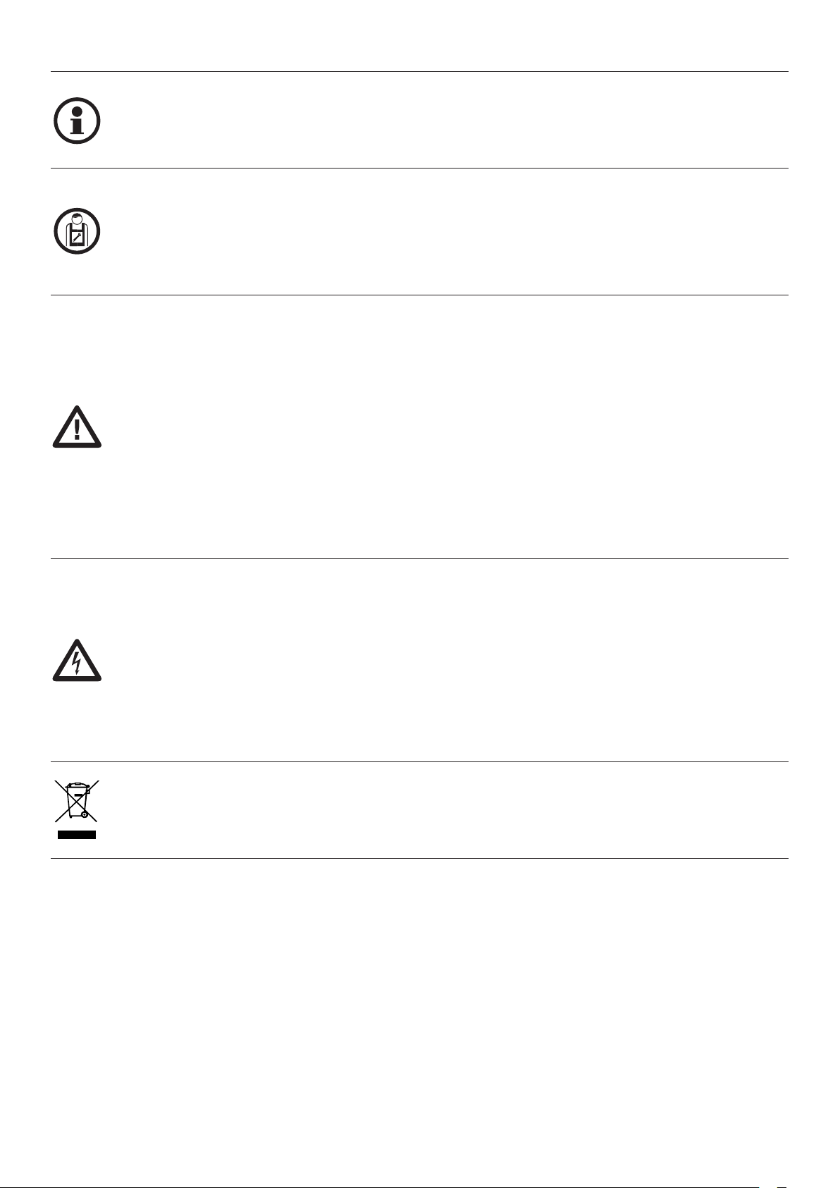
WASTE DISPOSAL
As indicated by the symbol shown, it is forbidden to dispose this product as normal urban waste as some parts might
be harmful for environment and human health, if they are disposed of incorrectly.
Therefore, the device should be disposed in special collection platforms or given back to the reseller if a new and similar
device is purchased.
An incorrect disposal of the device will result in fines applied to the user, as provided for by regulations in force.
Descriptions and figures in this manual are not binding. While leaving the essential characteristics of the product unchanged, the
manufacturer reserves the right to modify the same under the technical, design or commercial point of view without necessarily
update this manual.
WARNING
3
Page 4

GENERAL RECOMMENDATIONS
Automatismi Benincà SpA is not liable for damage caused by improper use or by incorrect installation of products or components.
WARNING: Important safety instructions. Follow all instructions since incorrect installation can lead to severe injury.
If this is the first time you realise an automation for swing gates with KMB24, we recommend that you read this manual carefully as
it contains important advice and information for the realisation of the plant in safe conditions.
Keep the various components on hand to gain confidence with them while reading this manual.
Keep this manual for future use
Attention!
Potentially dangerous operations. Scrupulously respect the indications given.
Useful indication.
Suggestions and recommendations for simplifying and/or improving the installation operations.
The automation of a door cannot be considered the only device for protection against intrusion.
Do not use any of the components in unsuitable environments (salty, acid or potentially explosive atmosphere)
All operations that require the protection shells of the devices opened, must take place without mains power supply.
Check that the temperature range marked on the drive is suitable for the location.
The drive cannot be used with a driven part incorporating a wicket door (unless the drive cannot be operated with the wicket door
open).
Ensure that entrapment between the driven part and the surrounding fixed parts due to the opening movement of the driven part is
avoided.
After installation, ensure that the mechanism is properly adjusted and that the protection system and any manual release function
correctly.
PRODUCT DESCRIPTION
DESTINATION OF USE
This product is destined exclusively for the opening and closure of swing doors for residential use, characterised by dimensional
limits and weight as indicated in this manual in the “Limits of use” paragraph”.
No other use is allowed.
BENINCÀ is not liable for uses that are not in compliance with those indicated in these instructions.
The kit is made up from two electromechanical operators with 24Vdc motor (LOW VOLTAGE), which allows movement of the leaves
via an articulated anti-shearing arm. The irreversible electromechanical gear motori keeps the gate locked in the closing and opening
positions.
Functioning is controlled by and electronic control unit, installed in one of the two operators.
The control unit commands the movement of the two motors and the functioning of the various accessories.
PRELIMINARY CHECKS
Before installation it is indispensable to perform several checks:
• Check the solidity of the structure installed in relation to the forces generated by the motor. Attach the motor stably using adguate
materials.
• The pillars supporting the leaves must be suitable for fixing the gear motors.
• If avialable, check the contenent of the EC declaration of conformity of the manual gate.
• If necessary, carry out the structural calculation and attach it to the technical file.
• Carry out the analysis of the risk and choice of solutions in accordance with the Machinery Directive 2006/42/CE and the standards
EN 13241-1, EN 12453, EN 12445.
Referer to Fig.4:
A - Impact and crushing of the main closing edge.
B - Impact and crushing in the area of opening.
C - Impact in the area of closure.
the KMB24 has been built to guarantee the PL c (Performance Level c), category 2, according to the EN 13849-1 standard(Safety
of Machinery).
• Try and open the gate manually, the leaves must move without effort and without points of resistance for the entire run.
• When left in any intermediate position the leaf must not move.
• The hinges and components subject to wear must be in perfect working condition. If this is not the case, replace the faulty parts.
• With the gate completely closed, check that the leaves are aligned perfectly along their entire length.
• The presence of a opening and closing stop is indispensable (Fig.3 ref. 5 and 8). It mist be installed if not present.
The reliability and safety of the automation depend on the state of the gate structure.
Check that there is enough space for installation of the operator in safe and comfortable conditions.
4
Page 5
A
C
DE B
184
234
28
1 2
10
184
234
28
245
184
35
95
α°
A (mm) B (mm) C (mm) D (mm) E (mm)
Door leaf max. rotation
90° 0 470 350 243 140
350
350
90° 50 470 339 255 140
90° 100 470 331 262 140
90° 150 470 328 264 140
90° 185 470 356 237 160
90° 200 440 410 160 200
110° 0 420 244 318 200
105° 100 420 262 310 200
3
A
11
H
I
12
M
4
D
9
F
A
1
7
8
3
L
5
2
B
6
5
E
C
G
5
Page 6

4
57
27,5
140 mm min.
A
B
C
B
5
5
6
6
Page 7

57
27,5
140 mm min.
7
Articulated bracket
Bracket
8 9
YES!
NO!
10
Screw M8x65
A
Fixing bracket
Self locking nut M8
7
Page 8

1 2
see label manual relase
11 12
GND
LN
T
SN
S
Customized key C
A
P
B1
T1
N
R
D
S1
B2
Lever L
13
GND
14
SWC2 (17) SWO2 (16) COM (13) M2 (3,4)
Cavi
LN
Cables
MBE24V
MB24V
8
Page 9

15
Key
Lower cam
Key
Upper cam
Open.
Close.
Upper cam
Microswitch
Key
Lower cam
Open.
Upper cam
Key
Close.
Lower cam
16
MB24
MBE24
Inside.
Open. Open.
Left Right
9
Page 10

17
F2:1.6AT (230V)
F2:3.2AT (115V)
N
L
+-
24Vac
II°CH/SERL
ANT
ANT
SHIELD
32313029
T 2A
F1
Code
____
J1 DAS
Close
DAS 8K2
DAS
J1 DAS
Open
DAS N.C.
1 2 3 4 5 6 7 8 9 10 11 12 13 14 15 16 17 18 19 20 21 22 23 24 25 26
U11
2827
RADIO
2827
DAS
8k2
M1 M2
SCA
LAMP
Lock 12Vdc
24Vdc
10
10W (5s)
PHOTO
TEST
(+) (-)
24Vac/dc
500mA max
COM
SWC1
SWO1
P.P.
STOP
SWO2
PHOT
SWC2
PHOTC
OPEN
PED
CLOSE
COM +
Page 11

18
TX2
TX1
PHOT C
RX2
PHOT
RX1
PHOTOCELLS ACTIVE IN OPENING AND CLOSING PHOTOCELLS ACTIVE IN OPENING AND CLOSING
PHOTOTEST
24Vac
11
12 11 1213 18 13 199 10
test1:on test2:ON
COM PHOT COM PHOT-C
PHOTOTEST
24Vac
9 10
19
24Vac 24Vac
NC NO
RX1TX1
SCA
24Vac/dc
500mA max
11 12
AUX1:0
32313029
COM
24Vac 24Vac
SERVICE/ZONE LIGHT
Relè 24Vac
24Vac/dc
500mA max
11 12
L N
32313029
Service Light
Service/Zone
Light
230Vac
NC NO
COM
RX2TX2
AUX1:2
Zone Light
AUX1:3
11
Page 12

Display OFF
Power ON
Firmware Ver. (3s)
Diagnostic
v1.05
8888
PAR
tca
tm1
tm2
tped
pmo1
pmc1
pmo2
pmc2
tdmo
40
50
50
50
50
50
PRG
5
5
2
PRG
PRG
PRG
PRG
PRG
PRG
PRG
PRG
LOG
tca
IBL
IBCA
SCL
PP
PRE
ham
blco
blcc
tdmc
tls
tloc
sld1
sld2
spd1
spd2
pso1
psc1
pso2
60
50
50
99
99
20
20
20
3
5
PRG
PRG
PRG
PRG
PRG
PRG
PRG
PRG
PRG
PRG
soft
ltca
htr
imot
cvar
mloc
bb
2ch
tst1
tst2
tstm
rem
TCA
TCA
psc2
seau
sear
tinc
20
0
0
250
PRG
PRG
PRG
PRG
radi
LOG
12
Page 13

on PRG
RADI
pp
PUSH OK
OFF PRG
OFF PRG
OFF PRG
OFF PRG
OFF PRG
OFF PRG
off PRG
off PRG
OFF PRG
Off PRG
off PRG
off PRG
par
Nman
MACI
RES
AUTO
CODE
2ch
ped
clr
rtr
PUSH OK
PUSH OK
PUSH OK
rtr PRG OK
0012 3456
OFF PRG
res PRG
PUSH
0000 conf OK
2 Cycle
OPEN/CLOSE
OK
9000 9C5a
RE-ENTER
CODE
Display OFF
off PRG
off PRG
off PRG
OFF PRG
Off PRG
off PRG
off PRG
off PRG
Legenda
Press key (-)
Press key (+)
Press key (PG)
Press simultaneously keys (+) and (-)
Increase/decrease the value with keys (+) and (-)
Press the transmitter key, which is to be assigned to function
13
Page 14

INDEX
1) LIMITS FOR USE....................................................................................................................................................................................... 15
2) OVERALL DIMENSION (FIG.1) .................................................................................................................................................................... 15
3) INSTALLATION DIMENSIONS (FIG.2) .......................................................................................................................................................... 15
4) TOOLS AND MATERIALS ........................................................................................................................................................................... 15
5) STANDARD INSTALLATION (FIG.3).............................................................................................................................................................15
6) ANCHORING OF BRACKETS (FIG.6-7) ........................................................................................................................................................ 15
7) POSITIONING THE GEARED MOTOR (FIG.10) .............................................................................................................................................15
8) POSITIONING THE ARTICULATED ARM BA (FIG.11) .................................................................................................................................... 15
9) MANUAL AND EMERGENCY OPERATION (FIG.12) ......................................................................................................................................16
10) WIRE CONNECTIONS (FIG.3) ................................................................................................................................................................... 16
11) ADJUSTING THE LIMIT SWITCHES (FIG.15) ............................................................................................................................................. 16
12) CHECKS ................................................................................................................................................................................................ 16
12.1) CHECKS INSTALLING POSITIONS ....................................................................................................................................................16
12.2) CHECK MOTOR AND LIMIT SWITCHES CONNECTIONS ..................................................................................................................... 17
13) SAFETY DEVICES (FIG.16) ....................................................................................................................................................................... 17
14) CP.MBY24 CONTROL UNIT ..................................................................................................................................................................... 17
14.1) AUTOSET FUNCTION ....................................................................................................................................................................... 17
14.2) WIRE DIAGRAM .............................................................................................................................................................................. 18
15) PROGRAMMING ..................................................................................................................................................................................... 19
16) PARAMETERS, LOGIC AND SPECIAL FUNCTIONS ....................................................................................................................................19
16.1) PARAMETERS (PAR) ....................................................................................................................................................................... 19
16.2) LOGIC (LOG)...................................................................................................................................................................................20
16.3) RADIO (RAD) .................................................................................................................................................................................. 22
16.4) CYCLES NUMBER (NMAN) ............................................................................................................................................................... 22
16.5) MAINTENANCE CYCLES (MACI) ...................................................................................................................................................... 22
16.6) RESET (RES) .................................................................................................................................................................................. 22
16.7) AUTOSET (AUTO) ........................................................................................................................................................................... 22
16.8) PROTECTION CODE (CODE) ............................................................................................................................................................ 23
17) TRANSMITTERS REMOTE LEARNING ......................................................................................................................................................23
18) FUSES ................................................................................................................................................................................................... 23
19) EMERGENCY BATTERY OR SOLAR PANEL ............................................................................................................................................... 23
20) DIAGNOSTICS ........................................................................................................................................................................................ 23
21) ERROR MESSAGES ................................................................................................................................................................................ 24
22) INSPECTION AND COMMISSIONING ........................................................................................................................................................ 24
TECHNICAL DATA
Power supply
Motor feed
Power drawn
Current drawn
Torque max.
Noise level
Working Temperature
Operating time at 90°
Door leaf max. weight
Door leaf max.
Duty cycle
Lubrication
Index Protection
Weight
Built-in release:
14
MBE24 (With Control Unit) MB24
230 Vac ± 10%
24 Vdc
160 W
0,76 A
180 Nm
<70 dB
-20°C/+50°C
10 s (with slowdown disabled)
300 kg (see limits for use)
3,0 m (see limits for use)
30 min. ON /30 min. OFF
Permanent grease
IP44
10,7 kg
Customized key
10 s (with slowdown disabled)
300 kg (see limits for use)
3,0 m (see limits for use)
30 min. ON / 30 min. OFF
24 Vdc
160 W
6,2A
180 Nm
<70 dB
-20°C/+50°C
Permanent grease
IP44
9 kg
Customized key
--
Page 15

1) LIMITS FOR USE
Do not use the automation on leaves with dimensions / weights above the values indicated in the below enclosed table chart:
Door leaf width
(m)
1
1,5
2
2,3
Door leaf weight
(kg)
300
250
215
200
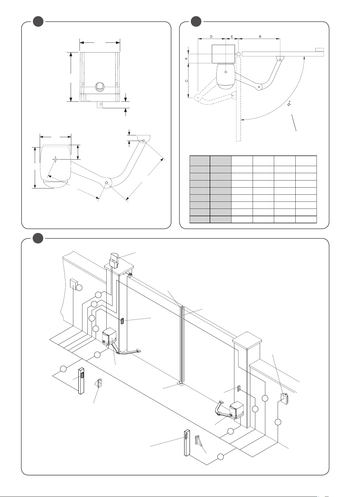
2) OVERALL DIMENSION (FIG.1)
On Fig 1 main overvall dimensions are indicated, value to be in millimiters.
3) INSTALLATION DIMENSIONS (FIG.2)
On Fig. 2 and enclosed table chart , different installation dimensions are indicated.
Any change on the A, B, E dimensions, C and D dimensions changes accordingly.
Verify to have enough space to guarantee the necessary articulated arm movement before proceeding with the installation.
4) TOOLS AND MATERIALS
Make sure that there are all tools and materials necessary for installation (fig.5). Also check that they are in compliance with Standards and in perfect working order.
Use suitable individual protection devices I.P.D. (goggles, gloves, etc)
The length and type of connection cables depend on the accessories installed (see “Electric connections” paragraph).
The fixing screws for the gear motor are not supplied as they depend on the features of the materials used for the pillars
and the leaves.
5) STANDARD INSTALLATION (FIG.3)
On Fig. 3 a standard installation complete with the main accessories is showed.
Keys
1 MBE.24 with control unit CP.MBY24
2 MB.24
3 Wall Photocell transmitter TX1
4 Wall Photocell receiver RX1
5 Opening leaf stop
6 Internal Photocell transmitter TX2
7 Internal Photocell receiver RX2
8 Closing leaf stop
9 Key selector
10 Flashing signal light connection with aerial
11 Safety edge Left leaf
12 Safety edge Right leaf
6) ANCHORING OF BRACKETS (FIG.6-7)
Once the fixing value “E”(fig.2) it taken from the relevant table, and considering a minimum height from floor of 100mm, fit the bracket
to the pillar by means of the screws M8 with relevant screw anchors.
Once the fixing value “B” is calculated, fit the articulated bracket to the gate with the same screws M8 and relevant screw anchors
or weld it to the gate by aligning the articulation bracket to the fitting bracket for the pillar, as shown in the drawing. Reinforce the
fitting areas which are not sufficiently thick, or in any case not strong enough.
7) POSITIONING THE GEARED MOTOR (FIG.10)
Place the geared motor in the fitting bracket for assembly to pillar by using the special nuts and screws supplied.
8) POSITIONING THE ARTICULATED ARM BA (FIG.11)
- Release the gear motor (see paragraph “Emergency manual operation”)
- Insert pin P in the hole of the motor shaft A
- Join arm B1 to arm B2 and lock them by means of pin T1 and lock ring S1
- Fix the arms to the motor shaft A and lock them by means of nut D by inserting washer R and ring N
- Hook the arm to bracket SN and lock it by means of pin T1 and release ring S1.
- Apply cover C and fix it by means of the two screws V.
The gear motor can be installed on the other gate leaf (Fig. 6) in a similar way. The only difference between right-hand and left-hand
leaves relies in the position of arm B2.
With released gear motor, completely open the gate and check the operating clearances of the two arms.
15
Page 16

9) MANUAL AND EMERGENCY OPERATION (FIG.12)
To manually open or close the door in case of power failure or faults, two solutions are possible:
• Built-in release
Introduce the customized key C, turn it clockwise and pull lever L. At this point the geared motor is released and the gate can be
manually pushed.
To reset the normal operation, close lever L again and turn key C anticlockwise. Manually move the gate until the geared motor
is engaged again.
• Rope external release: optional
It is available for fitting to external wall or with accessory to be mounted flush (see MB.SE).
10) WIRE CONNECTIONS (FIG.3)
The cables necessary for the installation can vary according to the accessories installed.
No connection cable is supplied.
Fig. 3 indicates the cables for standard installation.
List of cables
Connection Type Maximum length and notes
A Mains power supply (MBE.24 with control unit CP.MBY24) 3x1,5mm
B Motor connection (MB.24 without control unit) 5x1,5mm
C Wall Photocell transmitter connection 2x0,5mm
D Wall Photocell receiver connection 4x0,5mm
E Column Photocell transmitter connection 2x0,5mm
F Column Photocell receiver connection 4x0,5mm
G Key selector connection for external command 4x0,5mm
H Flashing signal light connection 2x1,0mm
I Connection of the aerial built-in the flashing light RG 58
L Connection for safety edge Right leaf 2x1,0mm
M Connection for safety edge Left leaf 2x1,0mm
2
2
2
2
2
2
2
2
2
2
30m - [1]
15m - [2]
20m
20m
20m
20m
20m
10m
10m
10m
Note
An omnipolar switch should be provided with the contact opening of at least 3 mm, provided with overload protection and able to cut off the system from the mains.
[1]
Means for disconnections must be incorporated in the fixed wiring in accordance with the wiring rules.
The MBE24 gear motor can be installed indifferently on the right of left leaf.
It is preferable to install it on the leaf that is most easily reached by the electricity line.
It is recommended not to exceed 15 m in length. If it is indispensable to exceed this limit, increase the section of the
[2]
cable.
The cables used must be suitable for the type of connection. For example, for connection protected by raceways
use H03VV-F cables, for cables in the outdoor environment always use the H07RN-F type.
11) ADJUSTING THE LIMIT SWITCHES (FIG.15)
N.B.: The position of the cams referring to micro-switches varies according whether the installation of the geared motor is
lefthand or righthand, view from inside. Pay attention to diagrams.
• Closing limit switches
Release the geared motor and manually close the door.
Turn the related cam to the position shown by using the special key supplied, until the micro-switch is activated. Lock the cam
by tightening the central screw supplied.
• Opening limit switches
Release the geared motor and manually open the door.
Turn the related cam to the position shown by using the special key supplied, until the micro-switch is activated. Lock the cam by
tightening the two screws supplied.
12) CHECKS
12.1) CHECKS INSTALLING POSITIONS
1) Check that the arms are perfectly horizontal using a spirit level (fig.8).
If the arms are not perfectly horizontal, malfunctioning and breakage can occur. The shape of the holes on the fixing plate allows
any minimum adjustments.
2) With both gear motors released, take the leaves into the completely open position and check that the arms do not strike any
obstacle during movement.
Fig.9 represents the two motors installed, the dotted line indicates the two arms with the leaves in the opening position.
Control the presence and functionality of the mechanical block in closing “A”.
16
Page 17

12.2) CHECK MOTOR AND LIMIT SWITCHES CONNECTIONS
1) Cut-off power supply.
2) Manually release the wings, move them to approx. half-stroke and lock them again.
3) Restore power supply.
4) Send a step-by-step control signal by pressing the <-> push-button.
5) The leeaves must move in OPENING.
In case this does not happen, it is sufficient to invert among them the motor run wires. (1<>2 for M1 motor, and 3<>4 for M2
motor) and, if used, the relative Limit switch inputs (14<>15 for M1 motor, and 16<>17 for M2 motor).
13) SAFETY DEVICES (FIG.16)
IMPORTANT!
READ CAREFULLY!
Measure opening and closing forces (by means of the special instrument required by the standard EN 12445).
If the values of the forces are higher, install a protective device in accordance with the standard EN 12978 (for example
a sensitive edge) and repeat the measurement.
The dynamic forces can be reduced, for example, by reducing the speed of the leaf or using a sensitive edge wit high
elastic deformation.
BENINCÀ can provide all the devices necessary for your installation and relative accessories , contact your trusted
supplier for any further information.
On fig.16 an example of application on the primary closing edges.
To prevent the impact in the area of closure (figure 4, risk C) install a pair of photocells (recommended height 500 mm) so as to sense
the presence of the test paralleledpipe height 700 mm (in according to MD).
To reduce further the possibility of impact in the area of opening (figure 4, risk B) install a pair of photocells (recommended height
500 mm) in the area of movement of the gate, so as to sense the presence of the test paralleledpipe height 700 mm (in according
to MD).
We suggest to connect photocells in phototest mode (see Fig.18 and set logics TST1=ON e TST2=ON), or check the if photocell
working correctly at least every 6 months.
14) CP.MBY24 CONTROL UNIT
14.1) AUTOSET FUNCTION
IMPORTANT:
type of installation.
The AUTOSET function must be repeated at every function parameter change or upon change of automation conditions. See the
AUTO menu for further information.
The first and most important function to program is the self-regulation of the parameters, which allows the control unit to automatically set the end run points, the torque applied to the leaf and the slowing phases*.
To carry out autoset, proceed as follows:
a) Ascertain that no obstacles of any nature are present in the manoeuvre area, if necessary, block off the area in order to prevent
access from people, animals, vehicles, etc.
During autoset phase, the anti-crushing function is not active.
b) Select the AUTO function and press OK.
c) Select with the <+> or <-> button the submenu LSW.
LSW: if the motor is equipped with Limit switch.
d) once selected press OK to begin the autoset phase.
The control unit carries out a series of manoeuvres for learning of the run of the leves and for parameter configuration.
Perform an autostop procedure after every maintenance intervention or modification of the door.
After every autoset procedure and/or PMO/PMC,PSO/PSC parameters changing, measure opening and closing forces (by means
of the special instrument required by the standard EN 12445).
The control unit is equipped with the Autoset function to automatically set the main functioning values based on the
During the autoset operations, the control unit automatically performs several opening and closure manoeuvres.
Before proceeding, check that no person, animal or obstacle is or can be in the door manoeuvre area.
All the accessories provided for the system should be already connected to the control unit. If further accessories should
be added, self-adjustment must be repeated.
17
Page 18

14.2) WIRE DIAGRAM
Wire connections shown in Fig. 18 are described hereunder:
Terminal No. Function Description
1-2 Motor 1 Connection, motor 1: 24VDC PRE-WIRED
3-4 Motor 2 Connection, motor 2: 24VDC MB24
5-6 Flashing light Connection, flashing light 24VDC 15W max.
7-8 Lock Output, 12Vdc/10W power supply for electric lock (7:0V, 8:+12V)
Contact free from N.O. Voltage, may be configured as open gate indicator or photocell
test.
For use as “Open gate indicator” the TEST1 and TEST2 logics must be OFF
For use as photocell test it is sufficient to activate one or both TEST logics and connect
9-10
SCA/
PHOTO TEST
the photocells as indicated in Fig.3.
Output, accessory power supply, 24VAC/0.5A max.
11-12 24 Vac/dc
IMPORTANT: If the battery charger board is installed, the output (without mains power
connected) has a 24Vdc polarised voltage.
Make sure the devices are correctly connected (i.e. 11:+24Vdc / 12:-0Vdc).
13 COM Common for limit switch and all the command inlets.
14 SWO1 Motor 1 OPEN limit switch input (N.C. contact) PRE-WIRED.
15 SWC1 Motor 1 CLOSE limit switch input, (N.C. Contact) PRE-WIRED
16 SWO2 Motor 2 OPEN limit switch input, (N.C. Contact).
17 SWC2 Motor 2 CLOSE limit switch input, (N.C. Contact)
18 PHOT Input, photocell activated in both opening and closing phases
19 PHOT C Input, photocell activated in closing phase only (Normally closed contact)
20 STOP Input, STOP push-button (Normally closed contact)
21 OPEN
Input, OPEN push-button (Normally open contact).
It is possible to connect a timer for opening in time slots.
22 CLOSE Input, CLOSE push-button (Normally open contact)
23 PED
Pedestrian button input (N.O. Contact), controls the motor 1 opening, see TPED parameter.
24 Step-by-Step Input, step-by-step push button (Normally open contact)
25 COM Common for Limit switch and all the command inputs.
26 N/A N/A
Input, sensitive edge contact
Resistive edge 8K2: “DAS” Jumper closed (see paragraph 13 “SAFETY DEVICES”).
Mechanical edge N.C.: “DAS” Jumper open
When the edge is activated, the gate movement is stopped and reversed for about 3s.
27-28
SENSITIVE
EDGE
(DAS)
N.O. Contact free from Voltage, may be configured as second radio channel or service
29-30 II°CH/SERL
light. For use as second radio channel the 2CH logic must be ON.
For use as courtesy light the 2CH logic must be OFF.
31-32 Antenna Connection to the built-in radio receiver card (30-signal/31-screen).
+ / - 24VAC/dc
U11
18
CONFIGURATION
MEMORY
Input, 24VAC/24VDC power supply.
In case of use of plug batteries connect the battery charging card as indicated in the
specific installation instructions.
Extractable Eprom Memory. Contains all the control unit configurations (logics, parameters, etc.), including the radiotransmitters. In case of faults it is possible to extract Eprom
and insert it into a different control unit, avoiding reprogramming.
Page 19

15) PROGRAMMING
The programming of the various functions of the control unit is carried out using the LCD display on the control unit and setting the
desired values in the programming menus described below.
The parameters menu allows you to assign a numerical value to a function, in the same way as a regulating trimmer.
The logic menu allows you to activate or deactivate a function, in the same way as setting a dip-switch.
Other special functions follow the parameters and logic menus and may vary depending on the type of control unit or the software
release.
TO ACCESS PROGRAMMING:
1 – Press the button <PG>, the display goes to the first menu, Parameters “PAR”.
2 – With the <+> or <-> button, select the menu you want (PAR>LOG>RAD>NMAN>MACI>RES>AUTO>CODE).
3- Press the button <PG>, the display shows the first function available on the menu.
4 - With the <+> or <-> button, select the function you want.
5 - Press the button <PG>, the display shows the value currently set for the function selected.
6 - With the <+> or <-> button, select the value you intend to assign to the function.
7 - Press the button <PG>, the display shows the signal “PRG” which indicates that programming has been completed.
NOTES:
Simultaneously pressing <+> and <-> from inside a function menu allows you to return to the previous menu without making any
changes. Hold down the <+> key or the <-> key to accelerate the increase/decrease of the values.
After waiting 120s the control unit quits programming mode and switches off the display.
When the board is switched on, the software version is displayed for around 5 sec
Hold down the <+> key or the <-> key to accelerate the increase/decrease of the values.
16) PARAMETERS, LOGIC AND SPECIAL FUNCTIONS
The tables below describe the individual functions available in the control unit.
16.1) PARAMETERS (PAR)
MENU
TCA
TM1
TM2
Tped
PMo1
PMC1
PMo2
PMc2
TDMo
TDMC
TLS
TLOc
SLD1
Automatic closing time. Active only with logic “TCA”=ON.
At the end of the set time the control unit orders a closing manoeuvre.
Operating time, motor 1. The operating time is adjusted at normal speed during
motor 1 opening and closing phases. See Paragraph “Adjustment of the gate leaf
speed”.
By setting the value to 0, the operation is performed with around 2 seconds of
pick-up and then the movement is carried on at reduced speed for the entire
stroke. In the motors with encoder, the value is expressed in percentage. In motors without encoder the value is expressed in seconds.
Operating time, motor 2. The operating time is adjusted at normal speed during
motor 2 opening and closing phases. See Paragraph “Adjustment of the gate leaf
speed”.
By setting the value to 0, the operation is performed with around 2 seconds of
pick-up and then the movement is carried on at reduced speed for the entire
stroke. In the motors with encoder, the value is expressed in percentage. In motors without encoder the value is expressed in seconds.
Adjusts the motor 1 opening percentage (pedestrian function).
The value is expressed in seconds. In the motors with encoder, the value is
expressed in percentage. In motors without encoder the value is expressed in
seconds.
The anti-crash device (amperometric sensor) operation is adjusted in the opening
phase, at normal speed - Motor 1.
The anti-crash device (amperometric sensor) operation is adjusted in the closing
phase, at normal speed - Motor 1.
The anti-crash device (amperometric sensor) operation is adjusted in the opening
phase, at normal speed - Motor 2.
The anti-crash device (amperometric sensor) operation is adjusted in the closing
phase, at normal speed - Motor 2.
Mot.2 opening delay time.
Regulates the delay time of motor 2 on opening with respect to motor 1
Mot.1 closing delay time
Regulates the delay time of motor 1 on closing with respect to motor 2
SERL contact activation time (Service light) 29/30 terminals.
At each manoeuvre the contact closes for the set time.
See Figure 19 connection scheme.
Electric lock activation time. The value is expressed in 1/10s (0=0s - 50=5s) 0-50 (5=0,5s)
Adjusts motor 1 speed during slowing phases.
This value is expressed in percentage.
FUNCTION MIN-MAX-(Default) MEMO
1-240-(40s)
0-99-(5)
0-99-(5)
1-99 (50)
1-99-(50%)*
1-99-(50%)*
1-99-(50%)*
1-99-(50%)*
0-15-(2s)
0-40-(3s)
1-240-(60s)
30-70 (50%)
19
Page 20

SLD2
SpD1
SpD2
Pso1
Psc1
Pso2
Psc2
SeaU
SEAR
tinc
* 1: minimum force/torque - 99: maximum force/torque.
MENU FUNCTION ON-OFF-(Default) MEMO
TCA
IbL
ibca
SCL
PP
PRE
HAM
Blco
Blcc
Adjusts motor 2 speed during slowing phases.
This value is expressed in percentage.
Adjusts motor 1 speed during normal speed phase.
Value expressed in percentage.
Adjusts motor 2 speed during normal speed phase.
Value expressed in percentage.
The anti-crash device (amperometric sensor) operation is adjusted in the opening
phase, at reduced speed - Motor 1.
The anti-crash device (amperometric sensor) operation is adjusted in the closing
phase, at reduced speed - Motor 1.
The anti-crash device (amperometric sensor) operation is adjusted in the opening
phase, at reduced speed - Motor 2.
The anti-crash device (amperometric sensor) operation is adjusted in the closing
phase, at reduced speed - Motor 2.
NOT USED 0-99-(0%)
NOT USED 0-99-(0%)
NOT USED 1-250-(250)
16.2) LOGIC (LOG)
Enables or disables automatic closing
On: automatic closing enabled
Off: automatic closing disabled
Enables or disables condominium function.
On: condominium function enabled. The step-by-step impulse or transmitter
impulse has no effect during the opening phase.
Off: condominium function disabled.
The multi-flat function is enabled or disabled during the TCA counting.
On: the bloc of flat function is enabled. The Step-by-Step signal or the transmitter
signal has no effect during the TCA counting.
Off: the bloc of flat function is disabled.
Enables or disables rapid closing
On: rapid closure is enabled. With open gate, or in the opening phase, the
activation of the photocell causes the automatic closure 3sec after the total
opening of the gate. It is activated only with TCA:ON
Off: rapid closing disabled.
Selects the operating mode of the ”Step by step button” and of the transmitter.
On: Operation: OPEN > CLOSE > OPEN >
Off: Operation: OPEN > STOP > CLOSE > STOP >
Enables or disables pre-blinking.
On: Pre-blinking enabled. Blinking is activated 3s before the motor starts.
Off: Pre-blinking disabled.
Enables or disables the inversion stroke function
On: Function enabled. Before each opening manoeuvre the control unit orders a
manoeuvre of 2s in the opposite direction to facilitate the release of the electric
lock.
Off: Function disabled.
Enables or disables the block function in opening.
On: Block function enabled. After the intervention of the opening Limit switch the
control unit delays arrest by about 0.5s, so to allow a better strike of the shutter
on the stop locks.
Off: Block function disabled
Enables or disables the block function in closing.
On: Block function enabled. After the intervention of the opening Limit switch the
control unit delays arrest by about 0.5s, so to allow a better strike of the shutter
on the stop locks.
Off: Block function disabled.
30-70 (50%)
30-99 (99%)
30-99 (99%)
1-99-(20%)*
1-99-(20%)*
1-99-(20%)*
1-99-(20%)*
(ON)
(OFF)
(OFF)
(OFF)
(OFF)
(OFF)
(OFF)
(OFF)
(OFF)
20
Page 21

SOFT
LTCA
htr
1mot
Cvar
mloc
BB
2ch
TST1
TST2
TSTm
rem
Enables or disables start at decreased speed.
On: Executes start ups at decreased speed for 2 seconds to then shift to normal
speed.
Off: Start at decreased speed not active.
Selects the operating mode of the blinking light during the time TCA
On: Blinking light on during TCA
Off: Blinking light off during TCA
Enabled or disables HOLD-TO-RUN function
On: HOLD-TO-RUN function.
The pressure of the OPENS/CLOSES button must be maintained throughout the
entire manoeuvre. The opening of the STOP input stops the motor. All the safety
inputs are deactivated, except for the Limit switch inputs /SW01/SW02/SWC1/
SWC2).
Off: Automatic/semiautomatic function
The operating mode with 1 or 2 motors is selected:
On: The motor operation is synchronised. This function must be used in the following cases:
- for each single motor, connect it to M1: Terminals 1/2.
- for two synchronised motors (e.g. balancing doors), connect one motor to M1:
terminals 1/2 and the other to M2: terminals 3/4. Adjust the parameters related to
motor 1, the M2 limit switch inputs are deactivated. TDMO and TDMC must be 0.
Off: For two non-synchronised motors, e.g. overlapping gate leaves, adjust TDMO
and TDMC on the desired values.
The code programmable transmitters is enabled or disabled.
On: Radio receiver enabled only for rolling-code transmitters.
Off: Receiver enabled for rolling-code and programmable code transmitters (selflearning and Dip Switch).
Selects the type of electric lock used.
On: Magnetic electric lock, normally fed at 12Vdc.
Power is cut off to the electric lock output before each opening and closing
operation.
Off: Electric lock with latch, normally not fed.
Before each opening manoeuvre power is fed at 12Vdc for the time set by the
parameter TLOC.
Activates or deactivates the push in closing function. Only with logic SLD:ON
On: The last second of the manoeuvre in closing phase is carried out at normal
speed (disabling slowing) to favour a better hook of the electric lock.
Off: Function disabled.
Enables or disables the second radio channel on terminals 29/30.
On: Exit 29/30 configured with function as second radio channel.
Off: Exit 29/30 takes on function of service light (see parameter TLS).
Enables or disables checking of photocells on PHOT input, active both in closing
and in opening.
On: Check enabled. If the check has a negative result, no manoeuvre is commanded. See Fig.18 - “PHOTO TEST”.
Off: Checking of photocells disabled at each manoeuvre.
Enables or disables checking of photocells on PHOT-C inputs, active only in closing.
On: Check enabled. If the check has a negative result, no manoeuvre is commanded. See Fig.18 - “PHOTO TEST”.
Off: Checking of photocells disabled at each manoeuvre.
NOT USED (OFF)
(Enables or disables remote radiotransmitters learning, as indicated in the paragraph “Remote transmitters learning”.
On: Remote learning enabled.
Off: Remote learning not enabled.
(OFF)
(OFF)
(OFF)
(OFF)
(OFF)
(OFF)
(OFF)
(OFF)
(OFF)
(OFF)
(OFF)
21
Page 22

16.3) RADIO (RAD)
MENU
By selecting this function, the receiver goes in waiting (Push) for a transmitter code to assign to the step-step function.
PP
2Ch
ped
CLR
RTR
Displays the number of complete cycles (open+close) carried out by the automation.
When the <PG> button is pressed for the first time, it displays the first 4 figures, the second time it shows the last 4. Example
<PG> 0012 >>> <PG> 3456: made 123.456 cycles.
Press the key of the transmitter to assign to this function.
If the code is valid, it is memorised and the message OK is displayed
If the code is not valid, the message Err is displayed
By selecting this function, the receiver goes into waiting (Push) for a transmitter code to assign to the second radio
channel.
Press the key of the transmitter to assign to this function.
If the code is valid, it is memorised ad the OK message is displayed
If the code is not valid, the message Err is displayed.
By selecting this function, the receiver goes into waiting (Push) for a transmitter code to assign to the pedestrian
opening function (see parameter TPED).
Press the key of the transmitter to assign to this function.
If the code is valid, it is memorised ad the OK message is displayed
If the code is not valid, the message Err is displayed.
By selecting this function, the receiver goes into waiting (Push) for a transmitter code to erase from the memory.
If the code is valid, it is erased and the message OK is displayed
If the code is not valid or not present in memory, the message Err is displayed
Completely erases memory of the receiver. Confirmation of the operation is requested.
By selecting this function the receiver goes into waiting (Push) for a new PGM pressure to confirm the operation.
At end of erasing the OK message is displayed
16.4) CYCLES NUMBER (NMAN)
FUNCTION
16.5) MAINTENANCE CYCLES (MACI)
This function enables to activate the maintenance request notice after a number of manoeuvres determined by the installer.
To activate and select the number of manoeuvres, proceed as follows:
Press button <PG>, the display will show OFF, which indicated that the function is disabled (default value).
With the buttons <+> and <-> select one of the numeric values proposed (from OFF to 100). The values are intended as hundreds
of cycles of manoeuvres (for example: the value 50 indicates 5000 manoeuvres).
Press the OK button to activate the function. The display will show the message PROG.
The maintenance request is indicated to the user by keeping the indicator lamp lit up for other 10 sec after the conclusion of the
opening or closing operation.
16.6) RESET (RES)
RESET of the control unit. ATTENTION!: Returns the control unit to the default values.
Pressing the <PG> button for the first time causes blinking of the letters RES, pressing the <PG> button again resets the control
unit. Note: The transmitters are not erased from the receiver nor is the access password.
All the logics and all the parameters are brought back to default values, it is therefore necessary to repeat the autoset procedure.
16.7) AUTOSET (AUTO)
This function is used to set the optimal operating values of the automatic system and, at the end of the procedure, the LAG, OPERATING TIME and BRAKING parameter are adjusted.
To carry out autoset, proceed as follows:
a) Ascertain that no obstacles of any nature are present in the manoeuvre area, if necessary, block off the area in order to prevent
access from people, animals, vehicles, etc.
During autoset phase, the anti-crushing function is not active.
b) Select the AUTO function and press OK.
c) Select with the <+> or <-> button the submenu LSW.
LSW: if the motor is equipped with Limit switch.
d) once selected press OK to begin the autoset phase.
The control unit carries out a series of manoeuvres for learning of the run of the leves and for parameter configuration.
Initially both the leaves are brought to opening position, then after some opening and closing manoeuvres at different speeds, of
one or both the shutters, the control unit displays the message OK. In case the operation has no positive result, the message ERR
is displayed. Repeat the operation after re-checking the wiring and the eventual presence of obstacles.
In case parametersTM1/TM2 or the speed are changed, repeat the autoset procedure.
During the manoeuvres the display will show some abbreviations: OPM1/OPM2 during opening of the motor 1 or 2 and CLM1/
CLM2 during closing of motor 1 or 2.
22
Page 23

16.8) PROTECTION CODE (CODE)
It allows to type in an access protection code to the programming of the control unit.
A four-character alphanumeric code can be typed in by using the numbers from 0 to 9 and the letters A-B-C-D-E-F.
The default value is 0000 (four zeros) and shows the absence of a protection code.
While typing in the code, this operation can be cancelled at any moment by pressing keys + and – simultaneously. Once the password is typed in, it is possible to act on the control unit by entering and exiting the programming mode for around 10 minutes in
order to allow adjustments and tests on functions.
By replacing the 0000 code with any other code, the protection of the control unit is enabled, thus preventing the access to any
other menu. If a protection code is to be typed in, proceed as follows:
- select the Code menu and press OK.
- the code 0000 is shown, also in the case a protection code has been previously typed in.
- the value of the flashing character can be changed with keys + and -.
- press OK to confirm the flashing character, then confirm the following one.
- after typing in the 4 characters, a confirmation message “CONF” appears.
- after a few seconds, the code 0000 appears again
- the previously stored protection code must be reconfirmed in order to avoid any accidental typing in.
If the code corresponds to the previous one, a confirmation message “OK” appears.
The control unit automatically exits the programming phase. To gain access to the Menus again, the stored protection code must
be typed in.
IMPORTANT: TAKE NOTE of the protection code and KEEP IT IN A SAFE PLACE for future maintenance operations.
To remove a code from a protected control unit it is necessary to enter into programming with the password and bring
the code back to the 0000 default value.
IF YOU LOOSE THE CODE, PLEASE CONTACT THE AUTHORISED SERVICE CENTER FOR THE TOTAL RESET OF THE
CONTROL UNIT.
17) TRANSMITTERS REMOTE LEARNING
If an already memorised transmitter is available in the receiver it is possible to carry out remote radio learning (without needing to
access the control unit).
IMPORTANT: The procedure must be carried out with leaves in opening during TCA pause or with an open gate if the TCA
logic is OFF. The REM logic must be ON.
Proceed as follows:
1 Press the hidden key of the transmitter which is already memorised.
2 Press, within 5s, the key of the corresponding transmitter which is already memorised to associate to the new transmitter. The
flashing light will turn on.
3 Press within 10s the hidden key of the new transmitter.
4 Press, within 5s, the key of the new transmitter to associate to the channel chosen at point 2. The flashing light will turn off.
5 The receiver memorised the new transmitter and immediately exits from programming.
18) FUSES
F1: T2A low voltage protection.
F2: T1,6A high voltage protection.
19) EMERGENCY BATTERY OR SOLAR PANEL
Optional accessories are available for control unit power supply in case of absence of power or solar panel use.
For further information, refer to the instructions supplied with the accessory.
20) DIAGNOSTICS
SWO1 SWO2
SWC1
P.P. PED OPEN CLOSE
PHOT
PHOT-C
STOP
SWC2
DAS
One segment of the display is linked to each input. In the event of failure it switches on
according to the following scheme.
N.C. inputs are represented by the vertical segments. N.O. inputs are represented by
the horizontal segments.
The control unit sees the message AMP1 or AMP2 in case of anti-crushing ammeter
sensor intervention.
23
Page 24

21) ERROR MESSAGES
Some messages that are displayed in case of function anomalies are listed as follows:
Amp1
Amp2
Err1
Err2
Err3
Err4
Err5
Err6
Err7
Err8
thrm
Obstacle error motor 1/anti-crushing Check presence of obstacles on motor 1 leaf run
Obstacle error motor 2/anti-crushing Check presence of obstacles on motor 2 leaf run
Motor 1 circuit checking error Check motor 1 connections
Motor 2 circuit checking error Check motor 2 connections
error/fault power circuit Request technical assistance and eventually replace control unit.
PHOT photocell checking error Check connections, PHOT photocell alignment or presence of obstacles.
PHOTC photocell checking error Check connections, PHOTC photocell alignment or presence of obstacles.
Error edge active (during autoset) In autoset phase, the safety edge has intervened.
Error active stop (during autoset) In autoset phase, the STOP input has intervened.
Error active input (during autoset) In autoset phase a PP/Open/Close input has intervened.
Motor thermal protection intervention
Wait for motor cooling, in case reset does not take place, motor replacement may be necessary
22) INSPECTION AND COMMISSIONING
The respect for the indications given below is indispensable to guarantee the maximum safety of the automation.
The BENINCÀ authorised technician must perform all tests envisioned by the Law, Standards and Regulations in force
depending on the risks present, particularly respecting all requisites of the EN 12445 Standard, which establishes the test
methods for gate automations.
INSPECTION
1 Check that the model selected is suitable for the type of application and that all automation components have been installed
correctly, with respect to the indications in this manual.
2 Test opening and closure and control that the movement of the leaf is regular without friction points.
3 Check that all electric connections are made correctly and with cables that are in compliance with the Standards.
4 Check the correct functioning of photocells, transmitters, key selectors, manual release devices (see paragraph 13 “SAFETY
DEVICES”.
5 Take the measurement of the force of impact according to that indicated by the EN 12445 Standard, intervening, if necessary on
the parameters and repeat the measurement.
COMMISSIONING
Commissioning of the automation can only be performed if all of the previously-described inspection phases have had a
positive result.
1 Apply the warning plate, supplied with the automation, to the gate in a well-visible position.
2 Apply a plate to the gate that contains the following data: Type of automation, name and address of the person in charge of com-
missioning (manufacturer), serial number, year of manufacture and CE mark.
3 Realise the technical file as per indications of the EN 12445 Standard, attaching the entire drawing, electric wiring diagrams (e.g.
figure 3), risk analysis and solutions adopted, declaration of conformity of the manufacturer of the devices used (included in this
manual).
4 Fill in and supply the owner of the automation with the declaration of conformity.
5 Realise and supply the owner with the “user guide” for the automation, also using the user guide present in this manual.
6 Realise and supply the owner of the automation with the periodical maintenance plan.
7 Do not start the automation before the owner has been informed regarding the dangers and risks that are still present.
24
Page 25

KMB24
USER GUIDE
KEEP THIS GUIDE AND MAKE IT AVAILABLE TO ALL USERS OF THE AUTOMATION.
SAFETY STANDARDS
WARNING: Important safety instructions. It is important for the safety of persons to follow these instructions. Save these
instructions.
Do not stand in the movement area of the door.
Do not allow children to play with the commands or in proximity of the leaves.
Children should be supervised to ensure that they not play with appliance.
Do not allow children to play with fixed controls. Keep remote controls away from children;
In the case of functioning anomalies do not attempt to repair the fault but contact a BENINCÀ specialised technician.
MANUAL MOVEMENT FROM INSIDE
To manually open or close the door in case of power failure or faults, two solutions are possible:
• Built-in release
Introduce the customized key C, turn it clockwise and pull lever L. At this point the geared motor is released and the gate canbe
manually pushed.
To reset the normal operation, close lever L again and turn key C anticlockwise. Manually move the gate until the geared motor
is engaged again.
• Rope external release: optional
It is available for fitting to external wall or with accessory to be mounted flush (see MB.SE).
MAINTENANCE
• Periodically check the efficiency of the manual emergency release.
• The actuator does not require routine maintenance, however it is necessary to periodically check the safety devices and the other
parts of the plant that could create dangers following wear.
• Frequently examine the installation for imbalance and signs of wear or damage to cables, springs and mounting. Do not use if
repair or adjustment is necessary.
• Disconnect the supply when cleaning or other maintenance is being carried out, if the appliance is automatically controlled.
• Take good care of the maintenance book that the installer must supply you and make sure you respect the required maintenance
program.
• Check the efficiency of photocells at least every 6 months.
DISPOSAL
Whenever the product is put out of service, the legislative provisions in force must be followed regarding differentiated disposal and re-cycling of the various components (metals, plastics, electric cables, etc.). It is advised to contact a BENINCÀ
specialised technician or a specialised company that is enabled for this purpose.
C
L
25
Page 26

2
9
13
7
10
4
3
8
5
12
6
11
Pos.
1
2
3
4
5
6
7
8
9
10
11
12
13
Description
Cover
Motor
Screw
Limit stop
Microswitches
Shaft
Output shaft
Transformer
Control unit
Gasket
Release lever
Cover
Cover
1
Cod.
9686930
9686811
9686326
9686934
9686935
9686936
9686937
9686812
9686927
9686944
9686941
9686942
9686943
26
Page 27

UE Declaration of Conformity/Incorporation (DoC/DoI)
Manufacturer's name: Automatismi Benincà SpA
Address: Via Capitello, 45 - 36066 Sandrigo (VI) - Italia
Telephone: +39 0444 751030
Email address: sales@beninca.it
Person authorised to draft the technical documentation: Automatismi Benincà SpA
Product type: Electromechanical actuator 24V DC for swing gates
Model/type: KMB24
Accessories: LAMPI24.LED - PUPILLA - TO.GO WV - TOKEY
The undersigned Luigi Benincà, as the Legal Officer, declares under his liability that the aforementioned product complies with the provisions established by the following directives:
Directive 2014/30/UE OF THE EUROPEAN PARLIAMENT AND OF THE COUNCIL of 26 February 2014, on the harmonisation of the
laws of Member States relating to electromagnetic compatibility, according to the following harmonised regulations:
EN 61000-6-2:2005 + AC:2005, EN 61000-6-3:2007 + A1:2011.
Directive 2011/65/EU of the European Parliament and Council, dated 8 June 2011, on the restricted use of certain hazardous substances in
electrical and electronic devices (RoHS), according to the following standards:
EN 50581:2012
Directive 1999/5/EC OF THE EUROPEAN PARLIAMENT AND THE COUNCIL of March 9 1999 regarding radio devices and terminal
and telecommunications devices and the reciprocal recognisances of their conformity, according to the following concurred regulations:
ETSI EN 301 489-3 V1.4.1 (2002) + ETSI EN 301 489-1 V1.4.1 (2002) + ETSI EN 300 220-3 V1.1.1 (2000) + EN 60950-1 (2001)
Directive 2006/42/EC OF THE EUROPEAN PARLIAMENT AND OF THE COUNCIL of 17 May 2006, on machinery, which amends
Directive 95/16/EC, and complies with the requisites for the “partly completed machinery (almost machinery)” set forth in the EN132411:2003 regulation.
EN 60335-1:2012 + A11:2014; EN 60335-2-103:2015.
• The manufacturer declares that the pertaining technical documentation has been drawn up in compliance with Attachment VII B of the
2006/42/ EC Directive and that the following requirements have been complied with:
1.1.1 - 1.1.2 - 1.1.3 - 1.1.5 - 1.2.1 - 1.2.3 - 1.2.6 - 1.3.1 - 1.3.2 - 1.3.3 - 1.3.4 - 1.3.7 - 1.3.9 - 1.5.1 - 1.5.2 - 1.5.4 - 1.5.5 - 1.5.6 - 1.5.7 - 1.5.8
- 1.5.10 - 1.5.11 - 1.5.13 - 1.6.1 - 1.6.2 - 1.6.4 - 1.7.2 - 1.7.4 - 1.7.4.1 - 1.7.4.2 - 1.7.4.3.
• The manufacturer undertakes that information on the “partly completed machinery” will be sent to domestic authorities. Transmission
ways are also included in the undertaking, and the Manufacturer’s intellectual property rights of the “almost machinery” are respected.
• It is highlighted that commissioning of the “partly completed machinery” shall not be provided until the final machinery, in which it should
be incorporated, is declared compliant, if applicable, with provisions set forth in the Directive 2006/42/EC on Machinery.
• Moreover, the product, as applicable, is compliant with the following regulations:
EN 12445:2002, EN 12453:2002, EN 12978:2003
Benincà Luigi, Legal Officer.
Sandrigo, 08/02/2016.
The certificate of conformity in this document corresponds to the last review available at the time of printing and could differ for editorial
requirements from the original available from the manufacturer.
The most recent and complete certificate of conformity is available consulting the site: www.beninca.com or can be requested from:
Automatismi Benincà SpA - Sandrigo VI - ITALY.
Page 28

AUTOMATISMI BENINCÀ SpA - Via Capitello, 45 - 36066 Sandrigo (VI) - Tel. 0444 751030 r.a. - Fax 0444 759728
 Loading...