

Page 1
L8542498
04/2011 rev 3
KER
UNIONE NAZIONALE COSTRUTTORI
AUTOMATISMI PER CANCELLI, PORTE
SERRANDE ED AFFINI
Page 2

2
Dichiarazione CE di conformità Déclaration CE de conformité
EC declaration of confirmity Declaracion CE de conformidad
EG-Konformitatserklarung Deklaracja UE o zgodności
Con la presente dichiariamo che il nostro prodotto
We hereby declare that our product
Hiermit erklaren wir, dass unser Produkt
Nous déclarons par la présente que notre produit
Por la presente declaramos que nuestro producto
Niniejszym oświadczamy że nasz produkt
KER
è conforme alle seguenti disposizioni pertinenti:
complies with the following relevant provisions:
folgenden einschlagigen Bestimmungen entspricht:
correspond aux dispositions pertinentes suivantes:
satisface las disposiciones pertinentes siguientes:
zgodny jest z poniżej wyszczególnionymi rozporządzeniami:
Direttiva sulla compatibilità elettromagnetica (89/336/
CCE, 93/68/CEE)
EMC guidelines (89/336/EEC, 93/68/EEC)
EMV-Richtlinie (89/336/EWG, 93/68/EWG)
Directive EMV (89/336/CCE, 93/68/CEE) (Compatibilité
électromagnétique)
Reglamento de compatibilidad electromagnética (89/336/
MCE, 93/68/MCE)
Wytyczna odnośnie zdolności współdziałania elektromagne-
tycznego (89/336/EWG, 93/68/EWG)
Norme armonizzate applicate in particolare:
Applied harmonized standards, in particular:
Angewendete harmonisierte Normen, insbesondere:
Normes harmonisée utilisées, notamment:
Normas armonizadas utilzadas particularmente:
Normy standard najczęściej stosowane:
EN 55022, EN 61000-3-2, EN 61000-3-3, EN 50082-1
Data/Firma
Direttiva sulla bassa tensione (73/23/CEE, 93/68/CEE)
Low voltage guidelines (73/23/EEC, 93/68/EEC)
Tiefe Spannung Richtlinie (73/23/EWG, 93/68/EWG)
Directive bas voltage (73/23/CEE, 93/68/CEE)
Reglamento de bajo Voltaje (73/23/MCE, 93/68/MCE)
Wytyczna odnośnie niskiego napięcia (73/23/EWG, 93/
68/EWG)
Norme armonizzate applicate in particolare:
Applied harmonized standards, in particular:
Angewendete harmonisierte Normen, insbesondere:
Normes harmonisée utilisées, notamment:
Normas armonizadas utilzadas particularmente:
Normy standard najczęściej stosowane:
EN 60204-1, EN 60335-1
Data/Firma
Automatismi Benincà SpA
Via Capitello, 45
36066 Sandrigo (VI)
ITALIA
Page 3
3
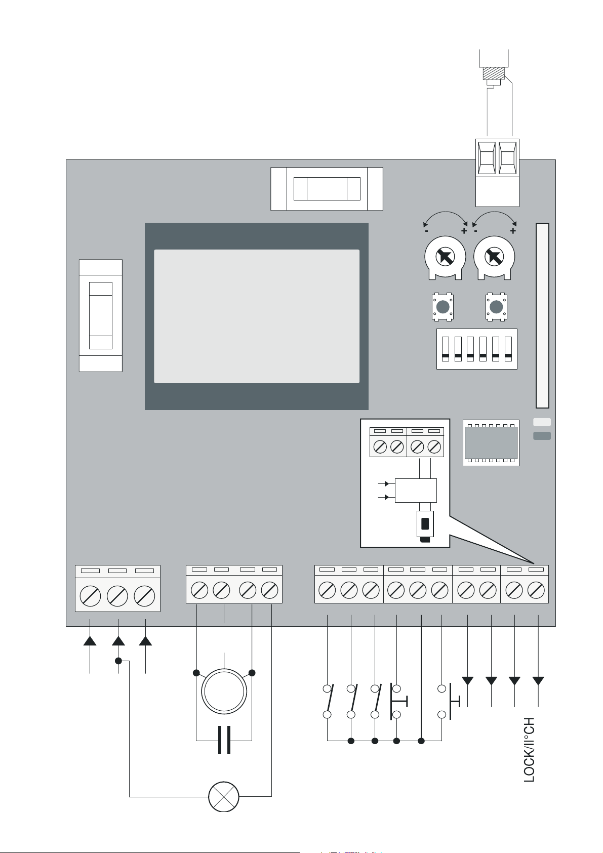
DL1
DL2
N
G N D
L
LAMP 115/230Vac
40W max
COM
M
C
24Vac
200mA max
P.P.
STOP
SWO
SWC
PHOT
COM
P1 P2
SW
1 6
TW TCA
1918
ANT
SHIELD
ANT
U2
F3
F2
Lock
12Vac
L
N
L OC K
D IP 5: O FF
F3 KER230: F6,3A
F3 KER115: F10A
F2: F315 mA
Page 4

8
KER control unit
The KER electronic control unit can be used to control 1 motor with power not higher than
750W.
GENERAL WARNINGS
a) The wire connections and the operating logic should be in compliance with regulations in
force.
b) The cables featuring different voltage should be physically detached, or adequately insulated
by an additional shield of at least 1 mm.
c) The cables should be further fastened in proximity to the terminals.
d) Check all connections before powering the unit.
e) Check that settings of the Dip-Switches are the required ones.
f) Normally Closed inputs which are not in use should be short-circuited.
INPUT/OUTPUT FUNCTIONS
Terminals Function Description
L-N-GND Power supply Input, 23VAC, 50/60Hz (KER)
Input, 115VAC, 50/60Hz (KER 115V)
(1-Phase/2-Neutral/GND-earth)
MOT-COM-MOT Motor Connection to motor:
(MOT-move/COM-Common/MOT-move)
N-BLINK LAMP Output, flashing light connection
KER: 230VAC 40W max.
KER 115V: 115VAC 40W max.
SWO SWO Input, OPEN limit switch (Normally Closed contact)
SWC SWC Input, CLOSE limit switch (Normally Closed contact)
PHOT(CHIUDE) PHOT Input, connection of safety devices, N.C. contact (e.g. photocells):
- in the closing phase, when the contact is opened the motor is
stopped and its direction is immediately reversed;
- in the opening phase, the triggering of the contact has no effect
on the motor.
In the “Service man” operating mode, this contact acts as CLOSE
control signal. In this case connect it to a N.O. (Normally Open)
button.
STOP STOP Input, STOP push-button (Normally Closed contact)
COM COM Common, for all control inputs.
P.P (OPEN). Step-by-Step Input, Step-by-Step push-button (Normally Open contact)
In the “Service man” operating mode, it acts as OPEN control.
24 VAC 24VAC Output, power supply of accessories, 24VAC/200mA max
SCA-SCA Ch.II/Lock Non-insulated, free contact.
Configurable output through DIP-SWITCH 5.
DIP5 ON: Output, second radio channel of the incorporated
receiver (24VAC/3W max).
DIP5 OFF: Connection to the Lock optional card for the control of
the electric lock.
Do not connect the electric lock directly to the output.
SHIELD-ANT Antenna Connection of the extractable radio receiver card and the built-in
radio module
(SHIELD- DISPLAY/ANT-signal).
Note:
The control unit is equipped with a “P2” button with the same functions as the Step-by-Step
button, useful to control the automatic system during installation.
Page 5

9
HOW TO CHECK CONNECTIONS:
1) Cut off power supply.
2) Manually release the door and push it for about half stoke. Lock the door again.
3) Restore power supply.
4) Send a step-by-step control through P2 push-button, P.P. input or radio-control signal.
5) The door must move in the opening phase. In the negative, with motor stopped, it is sufficient
to invert the motor and limit switch (MOT/MOT) wires (SWO/SWC).
6) Proceed by adjusting Times and operating Logics.
DIP-SWITCH FUNCTION
DipSwitches
Function Description
DIP1 Torque
adjustment /
radio
learning
It is possible to switch between the torque adjustment mode
and the radio learning.
Off: RADIO LEARNING mode (see section “Radio learning”)
On: TORQUE ADJUSTMENT mode (see section “Torque
Regulation”).
DIP2 Bloc of flats The bloc of flat function is enabled or disabled.
Off: the bloc of flat function is disabled.
On: the bloc of flat function is enabled.
The Step-by-Step signal or the transmitter signal has no effect
during opening.
DIP3 TCA Special The TCA special is enabled or disabled.
Off: Special TCA function is disabled.
On: Special TCA function is enabled.
If a PP control signal is sent in the first 5 seconds of the TCA
calculation, the TCA is ignored and the closing operation is
started.
If the PP control signal is sent after the first 5 seconds and
before the preset TCA time has elapsed, the time is reset and
the new TCA counting starts.
DIP4 P.P. : operating
mode
The operating mode of the “P.P. button” and of the transmitter
is selected.
Off: Operation: OPEN>STOP>CLOSE>STOP>
On: Operation: OPEN>CLOSE>OPEN>
DIP5 Radio channel II
/LOCK
The operating mode of the output to SCA terminals is selected
(for a correct operation of the logics see the table “Inputs/
outputs functions – SCA-SCA paragraph” at page 4).
Off: Impulse output for the control of the Lock card for electric
lock
On: Impulse output, radio channel II of the incorporated
receiver
DIP6
Step-by-Step:
3-STEP
mode
The 3 steps is enabled or disabled.
On: The PP control sequence is the following:
OPEN>STOP>CLOSE>OPEN>STOP>CLOSE>…
Off: The control sequence is the one preset by DIP 4.
NOTE: it operates with DIP 4 only on OFF.
Page 6

10
TRIMMER OPERATIONS
TW The maximum duration of the opening and closing operation is adjusted.
It should be preset at around 4sec more compared to the actual stroke time of the
system.
The adjustment varies from 3 sec minimum to 180 sec maximum.
TCA The automatic closure time can be adjusted.
The adjustment varies from 3 sec minimum to 180 sec maximum.
With TCA trimmer entirely turned clockwise, the LED DL2 (green) switches off
and the TCA is deactivated.
SERVICE MAN MODE
By moving all DIPs to ON, the control unit switches to the SERVICE MAN mode.
The PHOT input takes the CLOSE Button function (connect the push-button with a N.O.
contact).
The PP input acts as OPEN Button (connect the push-button with a N.O. contact).
The SWO and SWC inputs are disabled.
During the entire operation, the OPEN/CLOSE push-buttons must be kept pressed. When the
STOP input opens, the motor stops.
By pressing the OPEN/CLOSE buttons simultaneously, the motor stops.
TORQUE REGULATION (DIP1:ON)
When DIP1 is moved to ON, the card indicates the torque applied at that moment through a
number of flashes (from 1 to 4) of the DL2 green LED, followed by a 3 sec interval.
The maximum torque is indicated with the DL2 green LED with fixed light.
To increase the torque, press the P1 key. The DL2 LED changes the number of flashes to indicate
the selected torque value.
Once the desired torque is selected, to learn this setting move the DIP1 to OFF.
RADIO LEARNING (DIP1:OFF)
The KER control unit is equipped of a built-in radio module for the reception of variable code,
with 433.92 MHz frequency.
To use a remote control, its code must be stored in memory. The memorisation procedure is
shown hereunder. Up to 64 different codes can be stored in the memory of the device.
By pressing the P1 key, the control unit enters the radio self-learning phase: the red DL1 LED
flashes 1 time per second, awaiting for the key to be matched to the Step-by-Step function;
Once the key is learned, exit from the programming mode;
By pressing the P1 key twice, the red DL1 LED flashes two times per second and enters the
learning mode of Channel 2, radio/pedestrian*.
Once the key is learned, exit from the programming mode.
To exit the programming mode without learning any radio control code, press P1 key until the red
DL1 LED returns flashing in the “mains” power supply mode (see LED diagnostics, page 7).
* NOTE: Keep in mind that if DIP5 is OFF, the matched key acts as pedestrian key (opening for around 7
seconds), otherwise, with DIP5 to ON, the matched key operates as 2nd channel on the SCA output.
To reset the receiver memory, press P1 and P2 keys simultaneously and keep them pressed for
around 10 seconds (during this time-lapse, both DL1 and DL2 LEDs flash rapidly).
After ten seconds, the two LEDs remain switched on with fixed light. Release the push-buttons.
When the LEDs return to the initial configuration, this means that the control unit has performed
the resetting of the memory.
Page 7

11
Note:
The transmitters are stored in an EPROM memory (U2), which can be removed and repositioned
in a new KER control unit, if required.
For safety reasons, it is not possible to store transmitter codes into memory during the opening/
closing phases of the motor.
LED DISGNOSTICS
The red LED indicates the activation of inputs, according to the following legend:
STOP fixed light
PHOT rapid flashing
SWO 1 flash at every 2 second interval
SWC 2 flashes at every 2 second interval
OPEN+CLOSE 3 flashes at every 2 second interval
With slow flashing, the red LED indicates that the unit is powered from the mains.
The green LED indicates the movement direction of the motor and the status of the gate according
to the following legend:
OPENING 1 flash at every 1 second interval
CLOSING 2 flashes at every 1 second interval
Open gate without TCA fixed light
Open gate with TCA rapid flashing
Closed gate LED off
 Loading...