

Page 1
Pilot’s Guide
EFS 40/50
Bendix/King®4-inch/5-inch
Electronic Flight
Instrumentation System
n
Page 2
Page 3

Registration
This pilot's guide has been tailored by the installation and or certification agency to cover the following EFS 40/50 installation:
AIRCRAFT TYPE
AIRCRAFT TAIL OR SERIAL NUMBER
AIRCRAFT OWNER
EFIS TYPE (EFS 40 or EFS 50)
EFIS SYSTEM CONFIGURATION
EFIS SYSTEM SOFTWARE LEVEL
EFIS DISPLAY UNIT TYPE
EFIS CONTROL PANELS
REVERSIONARY MODES
Throughout this pilot's guide various configuration options are
described. A
check mark may be placed in the appropriate boxes to define which
configuration options are available in a given installation.
4o
(check box) precedes each configuration option. A
Page 4

Registration
Page 5

Table of Contents
TABLE OF CONTENTS
Section I
INTRODUCTION I.1
Section 1
SYSTEM CONFIGURATION 1.1
GENERAL 1.1
CONTROL PANEL 1.2
SYMBOL GENERATOR 1.3
EQUIPMENT INTERFACE & OPERATING CONFIGURATION 1.5
SOFTWARE 04 CONFIGURATION PAGES 1.6
SOFTWARE 05 CONFIGURATION PAGES 1.9
SOFTWARE 06 CONFIGURATION PAGES 1.12
SOFTWARE 07 CONFIGURATION PAGES 1.15
(includes both 0701 and 0702)
SOFTWARE 08 CONFIGURATION PAGES 1.18
SOFTWARE 09 CONFIGURATION PAGES 1.21
SOFTWARE 10 CONFIGURATION PAGES 1.25
SOFTWARE 11 CONFIGURATION PAGES 1.29
SOFTWARE 12 CONFIGURATION PAGES 1.33
SOFTWARE 13 CONFIGURATION PAGES 1.37
SOFTWARE 14 CONFIGURATION PAGES 1.41
SOFTWARE 15 CONFIGURATION PAGES 1.45
SOFTWARE 16 CONFIGURATION PAGES 1.48
Section 2
EHSI OPERATION 2.1.1
DETAILED OPERATING CONTROLS 2.1.1
EHSI CONTROLS (ED 461 & CP 467/468) 2.1.1
1-2 NAVIGATION SYSTEM SELECT 2.1.3
NAV NAVIGATION SENSOR SELECT 2.1.3
HSI 360° MODE SELECTION 2.1.5
BEARING POINTER SELECT 2.1.6
ARC SECTORED MODE SELECTION 2.1.7
RANGE SELECTION 2.1.8
TST/REF 2.1.8
TST— 2.1.8
REF GROUND SPEED
or TIME-TO-STATION selection 2.1.8
REF MAP FORMAT 2.1.9
COURSE SELECT KNOB 2.1.10
HEADING SELECT KNOB 2.1.10
DISPLAY BRIGHTNESS CONTROL 2.1.10
Issued 8/10
SW 04/05/06/07/08/09/10/11/12/13/14/15/16
TOC.1
Page 6

Table of Contents
EADI OPERATION 2.2.1
EADI DETAILED OPERATING CONTROLS 2.2.1
BRIGHTNESS 2.2.2
DH SET 2.2.2
RALT TST 2.2.2
RADAR OPERATION 2.3.1
RADAR CONTROLS, (CP 466A & CP 466B) 2.3.1
OFF-STBY-TST-ON 2.3.2
OFF 2.3.2
STBY 2.3.2
TST 2.3.2
ON 2.3.2
WX 2.3.2
WXA 2.3.2
GND MAP 2.3.2
LIGHTNING 2.3.3
VP 2.3.3
TRK 2.3.4
GAIN 2.3.5
PULL ARL 2.3.5
TILT 2.3.5
MFD OPERATION 2.4.1
MULTI FUNCTION DISPLAY CONTROL PANEL 2.4.1
CONTROL PANEL BUTTON OPERATIONS 2.4.2
COURSE SELECT KNOB/BUTTON 2.4.2
HSI BUTTON 2.4.2
ARC BUTTON 2.4.2
NAV BUTTON 2.4.2
1-2 BUTTON 2.4.3
BEARING #1 & #2 BUTTON 2.4.3
RANGE UP/DOWN BUTTON 2.4.3
JOYSTICK 2.4.3
WAYPOINT ENTRY OPERATION 2.4.3
PLAN VIEW OPERATION (available with 07 and higher) 2.4.4
CHECKLIST OPERATION(available with 08 and higher) 2.4.5
ENT BUTTON 2.4.5
WAYPOINT ENTRY OPERATION 2.4.5
PLAN VIEW OPERATION(available with 07 and higher) 2.4.5
CHECKLIST OPERATION(available with 08 and higher) 2.4.6
TEST/REFERENCE 2.4.6
CHECKLIST SELECT (available with 08 and higher) 2.4.6
TCAS ONLY SELECT (available with 08 and higher) 2.4.6
TOC.2
SW 04/05/06/07/08/09/10/11/12/13/14/15/16
Issued 8/10
Page 7

Table of Contents
Section 3
ABBREVIATED OPERATIONS 3.1
Section 4
EHSI DISPLAYS 4.1.1
EFS 40/50 COLOR STANDARDS 4.1.1
STANDARD EHSI DISPLAYS 4.1.1
NORMAL COMPASS CARD 4.1.1
NAVIGATION SOURCE ANNUNCIATION 4.1.2
SYMBOLIC AIRCRAFT 4.1.3
HEADING SELECT “BUG” 4.1.4
COURSE SELECT 4.1.4
LATERAL COURSE DEVIATION SCALE 4.1.5
LATERAL COURSE DEVIATION BAR 4.1.6
TO/FROM INDICATOR 4.1.6
DISTANCE, GROUNDSPEED and TIME-TO-STATION 4.1.6
DUAL MULTICHANNEL DME INSTALLATIONS 4.1.7
DME HOLD 4.1.8
BEARING POINTER 4.1.9
MAGNETIC/TRUE HEADING ANNUNCIATIONS 4.1.11
RADIO ALTITUDE 4.1.11
GLIDE SLOPE/VERTICAL NAVIGATION 4.1.11
WIND VECTOR 4.1.13
DRIFT ANGLE POINTER ( LNAV only) 4.1.13
LNAV MODE ANNUNCIATIONS 4.1.14
360 Map Displays 4.1.14
MAP 360 COMPASS CARD 4.1.15
SELECTED COURSE 4.1.15
MAP COURSE DEVIATION INDICATOR 4.1.16
TO/FROM 4.1.16
BEARING POINTER 4.1.16
REFERENCE WAYPOINT 4.1.16
RANGE RING 4.1.17
360-DEGREE MAP WX RADAR (IF EQUIPPED) 4.1.18
RDR 1400 WEATHER RADAR 4.1.19
LIGHTNING DETECTION 4.1.20
FULL TIME LNAV MAP 4.1.21
ARC (Expanded Sectored Mode) Displays 4.1.22
HDG BUG (ALL ARC FORMAT MODES) 4.1.22
COURSE DEVIATION INDICATOR
(EHSI ARC NON-MAP FORMAT) 4.1.22
Issued 8/10
SW 04/05/06/07/08/09/10/11/12/13/14/15/16
TOC.3
Page 8

Table of Contents
Custom (Non-Standard EHSI) Displays 4.1.23
DOPPLER 4.1.23
COMPASS CARD 4.1.23
DOPPLER VELOCITY BARS 4.1.23
VELOCITY AND TARGET SCALE 4.1.23
LNAV GROUND SPEED AND READOUT 4.1.24
WIND VECTOR INFORMATION 4.1.24
TARGET WAYPOINT 4.1.24
TENDENCY CIRCLE 4.1.24
MEMORY 4.1.24
HEADING BUG 4.1.24
CABLE 4.1.25
COMPASS CARD 4.1.25
ANGLE BARS 4.1.25
FUNNEL SCALE 4.1.25
WIND VECTOR INFORMATION 4.1.25
OPTIMUM CABLE POSITION CIRCLE 4.1.26
THRUST COMMAND 4.1.26
HEADING BUG 4.1.26
HOMING 4.1.26
LATERAL DEVIATION BAR 4.1.27
EADI DISPLAYS 4.2.1
NORMAL ATTITUDE DISPLAY 4.2.1
PITCH ATTITUDE 4.2.1
ROLL ATTITUDE 4.2.1
ROLL INDICATOR 4.2.2
Sky Pointer Roll Scale 4.2.2
Roll Indicator Scale 4.2.2
PERSPECTIVE LINES 4.2.2
SYMBOLIC AIRCRAFT 4.2.2
HEADING TAPE 4.2.3
FLIGHT DIRECTOR COMMAND BARS 4.2.3
AUTOPILOT/FLIGHT DIRECTOR MODE ANNUNCIATION 4.2.4
STANDARD 429 AUTOPILOT/FLIGHT
DIRECTOR MODE ANNUNCIATION 4.2.4
SFIM CDV AUTOPILOT/FLIGHT
DIRECTOR MODE ANNUNCIATION 4.2.7
RADIO ALTIMETER 4.2.8
DECISION HEIGHT SET 4.2.9
DECISION HEIGHT ALERT 4.2.9
PRECISION APPROACH MODE FORMAT 4.2.9
EXPANDED LATERAL DEVIATION SCALE 4.2.9
RISING RUNWAY 4.2.10
GLIDESLOPE/VERTICAL NAVIGATION 4.2.11
TOC.4
SW 04/05/06/07/08/09/10/11/12/13/14/15/16
Issued 8/10
Page 9

Table of Contents
EADI OFF-SIDE ILS/MLS 4.2.11
MARKER BEACON ANNUNCIATION 4.2.12
FAST/SLOW OR COLLECTIVE DISPLAY 4.2.12
MACH DISPLAY 4.2.13
RATE OF TURN DISPLAY 4.2.13
CATEGORY II ANNUNCIATOR 4.2.14
CATEGORY II OPERATION ANNUNCIATIONS 4.2.14
DUAL EFS SYSTEM 4.2.14
SINGLE EFS SYSTEM 4.2.15
CATEGORY II THRESHOLDS 4.2.16
ATTITUDE MONITOR 4.2.17
CROSS COMPARATOR ANNUNCIATORS 4.2.17
RA 4.2.17
LOC 4.2.17
GS 4.2.17
ATT 4.2.17
HDG 4.2.18
COMPOSITE DISPLAYS 4.3.1
COMPOSITE MODE 4.3.1
HEADING TAPE 4.3.1
SELECTED COURSE 4.3.1
HEADING BUG SELECT 4.3.1
NAVIGATION SOURCE ANNUNCIATION 4.3.2
LATERAL COURSE DEVIATION SCALE 4.3.2
LATERAL COURSE DEVIATION BAR 4.3.2
TO/FROM 4.3.3
DISTANCE INFORMATION 4.3.3
DME HOLD 4.3.3
MFD DISPLAYS 4.4.1
CRS, NOT CRS SELECT 4.4.1
WEATHER ONLY 4.4.1
TRACK LINE 4.4.1
VERTICAL PROFILE (VP) 4.4.1
SYMBOLIC AIRCRAFT 4.4.1
RANGE RINGS 4.4.2
ALTITUDE LINE 4.4.2
PROFILE ANGLE 4.4.2
PLAN VIEW NORTH-UP MAP 4.4.2
CHECKLIST INTERFACE 4.4.3
LOADING AND MODIFYING CHECKLIST DATA 4.4.3
CHECKLIST PAGE ORGANIZATION 4.4.4
ROOT INDEX PAGE 4.4.4
Issued 8/10
SW 04/05/06/07/08/09/10/11/12/13/14/15/16
TOC.5
Page 10

Table of Contents
SUB INDEX PAGES 4.4.5
CHECKLIST ITEM PAGES 4.4.5
NOTE PAGES 4.4.6
CLEARING CHECKLIST ITEMS 4.4.6
EMERGENCY PAGE ACTIVATION 4.4.6
CHECKLIST CONTROLS 4.4.7
Checklist: CHKLIST 4.4.7
Joystick 4.4.7
Enter : ENT 4.4.8
HSI 4.4.9
ARC 4.4.9
NAV 4.4.9
Up Arrow 4.4.9
Down Arrow 4.4.9
1-2 4.4.9
RMI 1 4.4.10
RMI 2 4.4.10
CRS (NOT) SEL 4.4.10
TST REF 4.4.10
CRS Knob 4.4.10
REMOTELY MOUNTED SWITCHES 4.4.10
FAULT ANNUNCIATIONS 4.4.10
TCAS INTERFACE 4.4.11
TCAS ONLY SELECTION 4.4.11
TCAS DISPLAY FORMAT 4.4.12
TCAS TRAFFIC SYMBOLOGY 4.4.12
Intruder Symbols 4.4.12
Vertical Speed Arrow 4.4.12
Data Tag 4.4.12
Off-Scale Traffic 4.4.13
TCAS DISPLAY ANNUNCIATIONS 4.4.13
Traffic 4.4.13
TCAS 4.4.13
TCAS Status 4.4.14
TCAS Mode 4.4.14
Range 4.4.15
Above/Norm/Below 4.4.15
No-Bearing Traffic 4.4.15
FLXXX and FL 4.4.15
EGPWS INTERFACE 4.4.16
EGPWS SELECTION 4.4.16
EGPWS DISPLAY FORMAT 4.4.16
EGPWS MODE/STATUS 4.4.16
EGPWS RANGE 4.4.16
TOC.6
SW 04/05/06/07/08/09/10/11/12/13/14/15/16
Issued 8/10
Page 11

Table of Contents
Section 5
OPERATING INSTRUCTIONS 5.1
PREFLIGHT PROCEDURES 5.1
START UP 5.1
SELF TEST 5.1
PUSH BUTTON TEST 5.1
PRE-TAKEOFF PROCEDURES 5.2
IN-FLIGHT OPERATION 5.2
ADF 5.2
LNAV (RNAV) 5.3
VNAV 5.3
APPROACH PROCEDURES 5.3
ILS APPROACH 5.3
BACK COURSE APPROACH 5.4
ADF APPROACH 5.4
LNAV (RNAV) APPROACH 5.4
VNAV GPS PRECISION APPROACH 5.4
VOR APPROACH 5.5
DECISION HEIGHT SELECTION 5.5
LIMITATIONS 5.5
EMERGENCY PROCEDURES 5.5
Section 6
FAULT ANNUNCIATIONS 6.1
GENERAL 6.1
EXTERNAL SYSTEM FAILURES 6.1
HEADING 6.1
ATTITUDE 6.1
FLIGHT DIRECTOR 6.1
EFS 40/50 SYSTEM FAILURES 6.1
DU—DISPLAY UNIT LOSS OF COOLING 6.1
SG—SYMBOL GENERATOR LOSS OF COOLING 6.1
CP—CONTROL PANEL (CP 467, CP 468,
ED 461 OR CP 470) 6.2
HEADING SELECT “BUG” 6.2
COURSE SELECT 6.2
RCP—RADAR CONTROL PANEL (if equipped) 6.2
SG—SYMBOL GENERATOR 6.2
RAW DATA DEVIATION ANNUNCIATIONS 6.3
BEARING POINTER ANNUNCIATIONS 6.3
ALPHANUMERIC READOUT ANNUNCIATIONS 6.3
CHECK CONFIG 6.3
Issued 8/10
SW 04/05/06/07/08/09/10/11/12/13/14/15/16
TOC.7
Page 12

Table of Contents
WEATHER RADAR ANNUNCIATIONS 6.4
WX FLT 6.4
WX OFF 6.4
BUSY VP 6.4
RT FLT 6.4
STB LMT 6.4
TGTALRT 6.4
TGT 6.4
429 FLT 6.4
ANT FLT 6.5
TX FLT 6.5
RANGE 6.5
STB OFF 6.5
WAIT 6.5
CUSTOM DISPLAY FAILURE ANNUNCIATIONS 6.5
DOPPLER/CABLE 6.5
EXTERNAL SYSTEM FAILURES 6.5
FMS Warning 6.5
Autopilot Warning 6.5
TCAS FAULT MESSAGES 6.6
Fault Messages for TCAS Fail 6.6
Fault Messages for No TCAS 6.6
LIGHTNING DETECTION DISPLAY FAULT MESSAGES 6.6
Section 7
REVERSIONARY MODES 7.1
CMPST - COMPOSITE 7.2
COPY OFF-SIDE 7.3
DISPLAY (EADI) DOWN 7.4
STBY - STANDBY 7.5
REVERSIONARY MODE SELECTION 7.6
THREE TUBE EFS 40/50 7.6
FOUR TUBE EFS 40/50 7.7
FIVE TUBE EFS 40 7.8
FIVE TUBE EFS 50 7.9
Section 8
GLOSSARY 8.1
ABBREVIATIONS 8.1
Section 9
INDEX 9.1
TOC.8
SW 04/05/06/07/08/09/10/11/12/13/14/15/16
Issued 8/10
Page 13

INTRODUCTION
Introduction
This pilot’s guide describes the
components, operation, and
operational procedures of the
BENDIX/KING EFS 40/50 Electronic Flight Instrumentation System (EFIS) containing system
software 04, 05, 06, 07, 08, 09,
10, 11, 12, 13, 14, 15, and 16.
The EFS40 system uses either a
single control display unit, four
inch ED 461, or a separate
C P 467 mode controller and four
inch ED 462 display unit for control and display of navigation data
and sensor selection. When a
Multi-Function Display is incorporated in the system, the
C P 469/A will control and select
navigation data for display on the
MFD. A CP 466A or CP 4 6 6 B
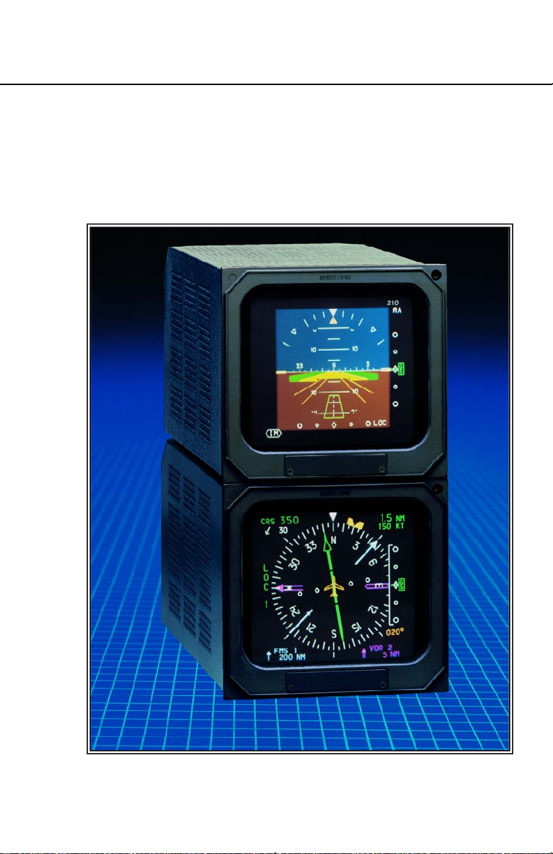
Equipment covered in this pilot's guide includes:
E D 4 6 1 Control display unit, 4" X 4"
E D 462 Display unit, 4" X 4"
S G 4 6 4 EHSI/MFD-only symbol generator
(not available with software 08 or later)
S G 4 6 5 EFIS symbol generator
C P 4 6 6 A R D S 81/82/84 radar control panel
C P 4 6 6 B R D S 86 radar control panel
C P 4 6 7 EFIS control panel with DH set and test
C P 4 6 8 EFIS control panel, less DH set and test
C P 4 6 9 MFD control panel
C P 4 6 9 A MFD control panel with Checklist,
TCAS and Joystick features
C P 4 7 0 EADI brightness and DH set and test panel
E D 5 5 1 Display unit, 5" X 5" (not available in current production)
E D 5 5 1 A Display unit, 5" X 5" (~16% larger symbols
compared with ED 461/2 presentation)
provides the radar control function when an RDS 81/82/84 or 86
weather radar is interfaced with
the system, and the associated
radar control/display unit is not
i n s t a l l e d .
The EFS 50 system uses a
remote CP 467 mode controller
and an ED 551/A display unit for
control and display of navigation
data and sensor selection. The
remote SYMBOL GENERATOR,
S G 464 or SG 465, interfaces
with the navigation sensors to
compute the display and EFIS
output data required by other
systems on board the aircraft.
The SG 464 is no longer available and has not been produced
with software versions 08 or later.
An Abbreviated Operations
section included in this manual
covers the functions of the EFS
SW 04/05/06/07/08/09/10/11/12/13/14/15/16
40/50 in minimal detail. The
Abbreviated Operations section
gives a brief visual overview of
I.1Issued 8/10
Page 14

Introduction
features and push button operations. However, it is necessary to
read the entire Pilot’s Guide for a
full understanding of the
E F S 40/50 system.
N o t e : The EFS 40/50 display
illustrations used in this pilot's
guide are artist's reproduc tions. Extreme care has been
taken to ensure the accuracy
of symbology placement and
relative size. However, it is
impossible to exactly duplicate
the display of a CRT and com pensate for all brightness lev els, as line width displayed on
the CRT varies with bright ness. In many cases, unrealis tic displays provide the most
informative display possible on
a single display. Therefore,
we ask that you use and treat
the graphic illustrations con taine
d in this pilot's guide as
they were intended. These
illustrations are to familiarize
the pilot with the type and
placement of data to be provid ed by the EFS 40/50.
ED 551A is the only version in
current production.
The data presented in this
pilot’ s guide is general in
nature and not tailored toward
a specific installation. Not all
equipment interfaces nor dis play options presented are cer tifiable in all aircraft types or by
all certification agencies. Each
installation may incorporate
different equipment comple ments and use different dis play options. For the unique
certified operating procedure
of a particular aircraft, refer to
the appropriate approved
Flight Manual Supplement for
that aircraft.
I.2
SW 04/05/06/07/08/09/10/11/12/13/14/15/16
Issued 8/10
Page 15

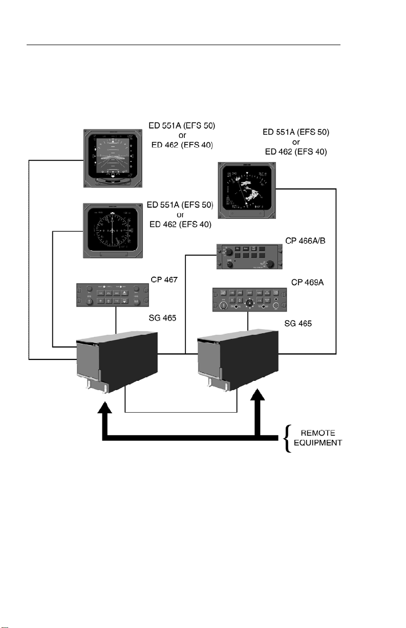
SYSTEM CONFIGURATION
System Configuration
GENERAL
Various configurations of the
E F S 40/50 system are currently
available to fulfill the particular
needs of the user. These configurations are differentiated by the
number of display units, type of
mode controller, number of symbol generators and the interfacing equipment.
The basic EFS 40 ( 2 tube four
inch Electronic Flight Instrumentation System) consists of:
• 1ea EHSI Control/Display
Unit (ED 4 6 1 )
• 1 ea EADI Display
Unit (ED 4 6 2 )
• 1 ea EADI control
panel (CP 4 7 0 )
• 1 ea Symbol Generator
( S G 4 6 5 )
• Or 1 ea remote EFIS
Control Panel (CP4 6 7 )
• 1 ea EHSI Display
Unit (ED 4 6 2 )
• 1 ea EADI Display
Unit (ED 4 6 2 )
• 1 ea Symbol Generator
( S G 4 6 5 )
The basic EFS 50 (2 tube five
inch Electronic Flight Instrumentation System) consists of:
• 1
ea remote EFIS Control
Panel (CP 467)
• 1 ea EHSI Display
Unit (ED 5 5 1 A ) ,
• 1 ea EADI Display
Unit (ED 5 5 1 A )
• 1 ea Symbol Generator
( S G 4 6 5 )
Beginning with software 09, a
configuration option was added
allowing an MFD only installation.
This option removes the heading
bug from the display allowing the
MFD SG to stand alone without
any other symbol generator in
the installation. The display unit
in this case can be either an ED
462 or ED 551A. The control
panel must be a CP 469A.
o MFD ONLY - no selected
heading bug.
Two new configuration options
for display unit (DU) type were
also added with software 09.
These options allow the MFD SG
to drive a 5” ED 551A MFD during normal operation and change
to eit
her ED 461 or ED 462 EHSI
and ED 462 EADI during standby
o p e r a t i o n .
o
MFD - ED 551A
EHSI - ED 461
EADI - ED 462
o
MFD - ED 551A
EHSI - ED 462
EADI - ED 462
Issued 8/10
SW 04/05/06/07/08/09/10/11/12/13/14/15/16
1.1
Page 16
System Configuration
ED 551/A MFD & CP 469A
2 EA ED 462 & CP 467
2 EA ED 551A & CP 467 ED 461, ED 462, & CP 470
Figure 1.1
CONTROL DISPLAY OPTIONS
CONTROL PANEL
The ED 461 Control/Display Unit
incorporates the EHSI mode controller in the bezel of the display,
reducing the required panel
space to 4” X 4”. For those installations that are not sensitive to
panel space, an independent display unit, ED 462, ED 551A, and
mode controller, CP 467, are
1.2
SW 04/05/06/07/08/09/10/11/12/13/14/15/16
offered. Figure 1.1 depicts the
E F S 40/50 Control Display
O p t i o n s .
Regardless of which display unit
and method of control is selected, the system’s performance will
be identical. Both mode controllers offer a simple means for
the pilot to select the desired display format, such as standard
Issued 8/10
Page 17
System Configuration
compass rose or sectored compass rose, 360-degree map or
sectored map and weather radar
overlay. Also incorporated on
the mode controller is the course
and heading select knobs with
auto sync. The auto sync feature
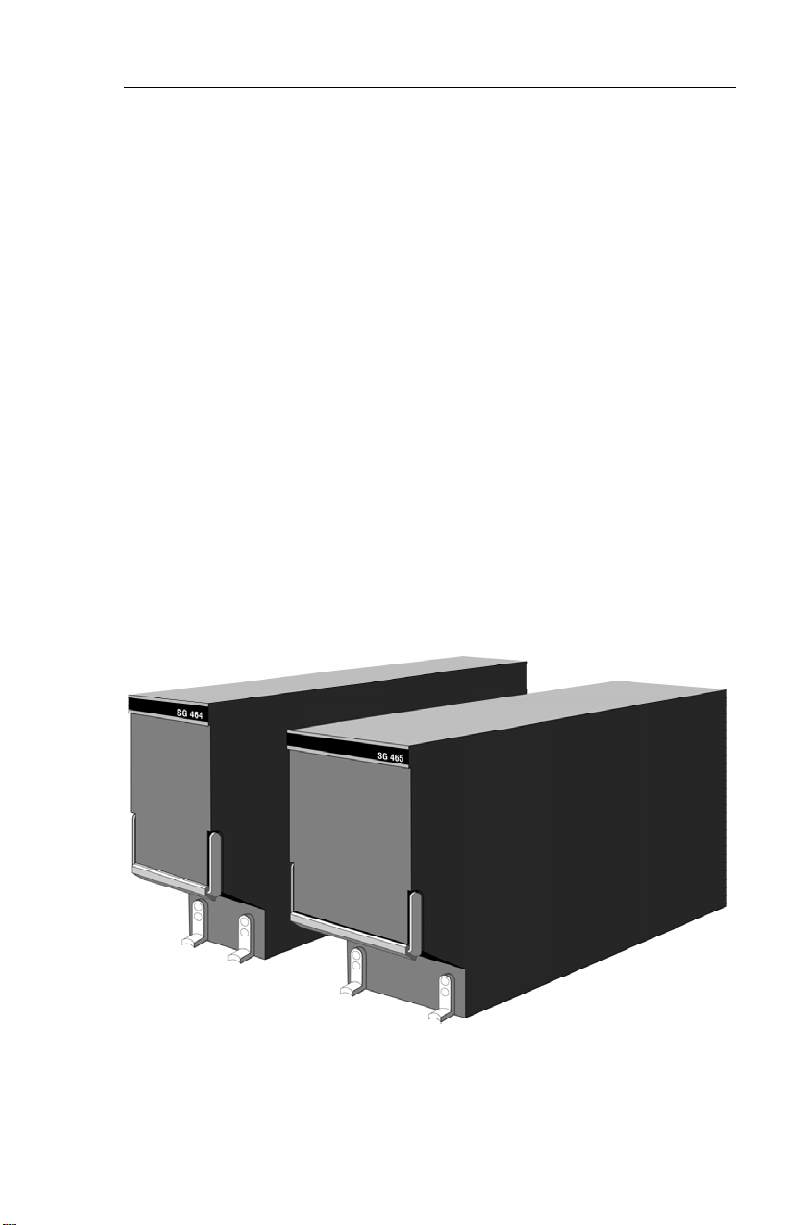
SYMBOL GENERATOR
The SG 464 EHSI/MFD-only
symbol generator is a remotemounted processing unit packaged in an ARINC 1/4 ATR short
form factor. The SG 4 6 5
EADI/EHSI/MFD symbol generator is a remote-mounted processing unit packaged in an ARINC
3/8 ATR short form factor. A version of the SG 465 3/8 ATR short
symbol generator is offered with
EHSI/MFD-only provisions.
will slew the heading bug to the
lubber line or the course pointer
to the DIRECT TO course for the
selected NAV sensor providing a
centered D-Bar. The CP 4 6 7
and CP 470 incorporate Decision
Height Set and Radio Altimeter
T e s t .
The SG 464 or SG 465 with software version 05 and above will
drive either the 4” X 4” (ED 4 6 1
or 462) or 5” X 5” (ED 551A) displays. Software version 06 incorporates the capability to drive the
E D 551 display. The SG 464 is
no longer available and has not
been produced with software versions 08 or later.
SG 464 AND SG 465 SYMBOL GENERATORS
Issued 8/10
Figure 1.2
SW 04/05/06/07/08/09/10/11/12/13/14/15/16
1.3
Page 18
System Configuration
1.4
Figure 1.3
TYPICAL EFS 40/50 SYSTEM BLOCK DIAGRAM
SW 04/05/06/07/08/09/10/11/12/13/14/15/16
Issued 8/10
Page 19

EQUIPMENT INTERFACE &
OPERATING CONFIGURATION
System Configuration
The EFS 40/50 equipment interface and operating configuration
is established at the time of
installation and certification. The
following pages are provided to
document the certified configura-
tion of a specific aircraft. Those
pages referring to software configuration versions not applicable
to this aircraft are to be removed
from this pilot’s guide.
Issued 8/10
SW 04/05/06/07/08/09/10/11/12/13/14/15/16
1.5
Page 20

System Configuration
SOFTWARE 04 CONFIGURATION PAGES
The EHSI, EADI, and Reversion software will display these pages. All
items will be identical among all 3 displays, however, the ADI will not
be able to show the rack configurations, instead it will show the configuration data coming from the HSI and the data in its own EEPROM.
The descriptions given in this section refer to side 1 (left side) as the
pilot’s side and side 2 (right side) as the co-pilot’s side.
— — — — — — — — — — |
1 VIEW/EDIT EQUIPMENT PG 01
2 I T E M
3 SG NUMBER _ _ _ _ _ _ _ _ _ _ _ _ _ _ _
4 S I N G L E / D U A L _ _ _ _ _ _ _ _ _ _ _ _ _ _ _
5 DU TYPE _ _ _ _ _ _ _ _ _ _ _ _ _ _ _
6 ATTITUDE/HDG #1 _ _ _ _ _ _ _ _ _ _ _ _ _ _ _
7 ATTITUDE/HDG #2 _ _ _ _ _ _ _ _ _ _ _ _ _ _ _
8 RATE OF TURN _ _ _ _ _ _ _ _ _ _ _ _ _ _ _
9 ADF #1 _ _ _ _ _ _ _ _ _ _ _ _ _ _ _
1 0 ADF #2 _ _ _ _ _ _ _ _ _ _ _ _ _ _ _
1 1 VOR/ILS #1 _ _ _ _ _ _ _ _ _ _ _ _ _ _ _
1 2 VOR/ILS #2 _ _ _ _ _ _ _ _ _ _ _ _ _ _ _
1 3 . . M O R E . .
— — — — — — — — — — |
1 VIEW/EDIT EQUIPMENT PG 02
2 I T E M
3 DME #1 _ _ _ _ _ _ _ _ _ _ _ _ _ _ _
4 DME #2 _ _ _ _ _ _ _ _ _ _ _ _ _ _ _
5 MLS #1 _ _ _ _ _ _ _ _ _ _ _ _ _ _ _
6 MLS #2 _ _ _ _ _ _ _ _ _ _ _ _ _ _ _
7 FMS #1 _ _ _ _ _ _ _ _ _ _ _ _ _ _ _
8 FMS #2 _ _ _ _ _ _ _ _ _ _ _ _ _ _ _
9 RNAV #1 _ _ _ _ _ _ _ _ _ _ _ _ _ _ _
1 0 RNAV #2 _ _ _ _ _ _ _ _ _ _ _ _ _ _ _
1 1 TACAN #1 _ _ _ _ _ _ _ _ _ _ _ _ _ _ _
1 2 TACAN #2 _ _ _ _ _ _ _ _ _ _ _ _ _ _ _
1 3 . . M O R E . .
1.6
SW 04/05/06/07/08/09/10/11/12/13/14/15/16
Issued 8/10
Page 21

System Configuration
— — — — — — — — — — |
1 VIEW/EDIT EQUIPMENT PG 03
2 I T E M
3 V N A V _ _ _ _ _ _ _ _ _ _ _ _ _ _ _
4 RADAR ALT _ _ _ _ _ _ _ _ _ _ _ _ _ _ _
5 AFCS TYPE _ _ _ _ _ _ _ _ _ _ _ _ _ _ _
6 AFCS COMMAND BAR _ _ _ _ _ _ _ _ _ _ _ _ _ _ _
7 AFCS MODE ANN _ _ _ _ _ _ _ _ _ _ _ _ _ _ _
8 AIR DATA _ _ _ _ _ _ _ _ _ _ _ _ _ _ _
9 RADAR TYPE _ _ _ _ _ _ _ _ _ _ _ _ _ _ _
1 0 RADAR CTL PNL _ _ _ _ _ _ _ _ _ _ _ _ _ _ _
1 1 RADAR INDICATOR _ _ _ _ _ _ _ _ _ _ _ _ _ _ _
1 2 C H E C K L I S T _ _ _ _ _ _ _ _ _ _ _ _ _ _ _
1 3 . . M O R E . .
— — — — — — — — — — |
1 VIEW/EDIT EQUIPMENT PG 04
2 I T E M
3 J O Y S T I C K _ _ _ _ _ _ _ _ _ _ _ _ _ _ _
4 RADAR GRAPHICS _ _ _ _ _ _ _ _ _ _ _ _ _ _ _
— — — — — — — — — — |
1 VIEW/EDIT OPERATING CHAR PG 06
2 I T E M
3 VERT SCALE SIDE _ _ _ _ _ _ _ _ _ _ _ _ _ _ _
4 DCLTR GS ON BC _ _ _ _ _ _ _ _ _ _ _ _ _ _ _
5 S P A R E _ _ _ _ _ _ _ _ _ _ _ _ _ _ _
6 DISPLAY WIND VEC _ _ _ _ _ _ _ _ _ _ _ _ _ _ _
7 DISPLAY DRIFT _ _ _ _ _ _ _ _ _ _ _ _ _ _ _
8 DG ONLY MODE _ _ _ _ _ _ _ _ _ _ _ _ _ _ _
9 DME DIST ONLY _ _ _ _ _ _ _ _ _ _ _ _ _ _ _
1 0 RADAR ONLY MODE _ _ _ _ _ _ _ _ _ _ _ _ _ _ _
1 1 HOVER MODE _ _ _ _ _ _ _ _ _ _ _ _ _ _ _
1 2 . . M O R E . .
Issued 8/10
SW 04/05/06/07/08/09/10/11/12/13/14/15/16
1.7
Page 22

System Configuration
— — — — — — — — — — |
1 VIEW/EDIT OPERATING PG 07
2 I T E M
3 DISPLAY HDG TAPE _ _ _ _ _ _ _ _ _ _ _ _ _ _ _
4 COMMAND BARS _ _ _ _ _ _ _ _ _ _ _ _ _ _ _
5 ROLL INDICATOR _ _ _ _ _ _ _ _ _ _ _ _ _ _ _
6 DCLTR UNUS ATT _ _ _ _ _ _ _ _ _ _ _ _ _ _ _
7 CAT II AVAILABLE _ _ _ _ _ _ _ _ _ _ _ _ _ _ _
8 PERSPECTIVE LINES _ _ _ _ _ _ _ _ _ _ _ _ _ _ _
9 DH SELECT _ _ _ _ _ _ _ _ _ _ _ _ _ _ _
1 0 CABLE MODE _ _ _ _ _ _ _ _ _ _ _ _ _ _ _
1.8
SW 04/05/06/07/08/09/10/11/12/13/14/15/16
Issued 8/10
Page 23

System Configuration
SOFTWARE 05 CONFIGURATION PAGES
The EHSI, EADI, MFD and Reversion software will display the following pages. All display information will be identical on the EHSI and
MFD, however, the EADI will not display the rack configurations, it will
display a comparison of the EHSI and EADI configuration data. The
descriptions given in this section refer to side 1 (left side) as the pilot’s
side and side 2 (right side) as the co-pilot’s side.
— — — — — — — — — — |
1 VIEW/EDIT EQUIPMENT PG 01
2 I T E M
3 SG NUMBER _ _ _ _ _ _ _ _ _ _ _ _ _ _ _
4 S I N G L E / D U A L _ _ _ _ _ _ _ _ _ _ _ _ _ _ _
5 DU TYPE _ _ _ _ _ _ _ _ _ _ _ _ _ _ _
6 ATTITUDE/HDG #1 _ _ _ _ _ _ _ _ _ _ _ _ _ _ _
7 ATTITUDE/HDG #2 _ _ _ _ _ _ _ _ _ _ _ _ _ _ _
8 RATE OF TURN _ _ _ _ _ _ _ _ _ _ _ _ _ _ _
9 ADF #1 _ _ _ _ _ _ _ _ _ _ _ _ _ _ _
1 0 ADF #2 _ _ _ _ _ _ _ _ _ _ _ _ _ _ _
1 1 VOR/ILS #1 _ _ _ _ _ _ _ _ _ _ _ _ _ _ _
1 2 VOR/ILS #2 _ _ _ _ _ _ _ _ _ _ _ _ _ _ _
1 3 . . M O R E . .
— — — — — — — — — — |
1 VIEW/EDIT EQUIPMENT PG 02
2 I T E M
3 DME #1 _ _ _ _ _ _ _ _ _ _ _ _ _ _ _
4 DME #2 _ _ _ _ _ _ _ _ _ _ _ _ _ _ _
5 MLS #1 _ _ _ _ _ _ _ _ _ _ _ _ _ _ _
6 MLS #2 _ _ _ _ _ _ _ _ _ _ _ _ _ _ _
7 FMS #1 _ _ _ _ _ _ _ _ _ _ _ _ _ _ _
8 FMS #2 _ _ _ _ _ _ _ _ _ _ _ _ _ _ _
9 RNAV #1 _ _ _ _ _ _ _ _ _ _ _ _ _ _ _
1 0 RNAV #2 _ _ _ _ _ _ _ _ _ _ _ _ _ _ _
1 1 TACAN #1 _ _ _ _ _ _ _ _ _ _ _ _ _ _ _
1 2 TACAN #2 _ _ _ _ _ _ _ _ _ _ _ _ _ _ _
1 3 . . M O R E . .
Issued 8/10
SW 04/05/06/07/08/09/10/11/12/13/14/15/16
1.9
Page 24

System Configuration
— — — — — — — — — — |
1 VIEW/EDIT EQUIPMENT PG 03
2 I T E M
3 V N A V _ _ _ _ _ _ _ _ _ _ _ _ _ _ _
4 RADAR ALT _ _ _ _ _ _ _ _ _ _ _ _ _ _ _
5 AFCS TYPE _ _ _ _ _ _ _ _ _ _ _ _ _ _ _
6 AFCS COMMAND BAR _ _ _ _ _ _ _ _ _ _ _ _ _ _ _
7 AFCS MODE ANN _ _ _ _ _ _ _ _ _ _ _ _ _ _ _
8 AIR DATA _ _ _ _ _ _ _ _ _ _ _ _ _ _ _
9 RADAR TYPE _ _ _ _ _ _ _ _ _ _ _ _ _ _ _
1 0 RADAR CTL PNL _ _ _ _ _ _ _ _ _ _ _ _ _ _ _
1 1 RADAR INDICATOR _ _ _ _ _ _ _ _ _ _ _ _ _ _ _
1 2 C H E C K L I S T _ _ _ _ _ _ _ _ _ _ _ _ _ _ _
1 3 . . M O R E . .
— — — — — — — — — — |
1 VIEW/EDIT EQUIPMENT PG 04
2 I T E M
3 J O Y S T I C K _ _ _ _ _ _ _ _ _ _ _ _ _ _ _
4 RADAR GRAPHICS _ _ _ _ _ _ _ _ _ _ _ _ _ _ _
5 HOMING #1 _ _ _ _ _ _ _ _ _ _ _ _ _ _ _
6 HOMING #2 _ _ _ _ _ _ _ _ _ _ _ _ _ _ _
— — — — — — — — — — |
1 VIEW/EDIT OPERATING CHAR PG 06
2 I T E M
3 VERT SCALE SIDE _ _ _ _ _ _ _ _ _ _ _ _ _ _ _
4 DCLTR GS ON BC _ _ _ _ _ _ _ _ _ _ _ _ _ _ _
5 FULL TIME FMS MAP _ _ _ _ _ _ _ _ _ _ _ _ _ _ _
6 DISPLAY WIND VEC _ _ _ _ _ _ _ _ _ _ _ _ _ _ _
7 DISPLAY DRIFT _ _ _ _ _ _ _ _ _ _ _ _ _ _ _
8 DG ONLY MODE _ _ _ _ _ _ _ _ _ _ _ _ _ _ _
9 DME DIST ONLY _ _ _ _ _ _ _ _ _ _ _ _ _ _ _
1 0 RADAR ONLY MODE _ _ _ _ _ _ _ _ _ _ _ _ _ _ _
1 1 HOVER MODE _ _ _ _ _ _ _ _ _ _ _ _ _ _ _
1 2 MFD NAV CONTROL _ _ _ _ _ _ _ _ _ _ _ _ _ _ _
1 3 . . M O R E . .
1.10
SW 04/05/06/07/08/09/10/11/12/13/14/15/16
Issued 8/10
Page 25

System Configuration
— — — — — — — — — — |
1 VIEW/EDIT OPERATING PG 07
2 I T E M
3 DISPLAY HDG TAPE _ _ _ _ _ _ _ _ _ _ _ _ _ _ _
4 COMMAND BARS _ _ _ _ _ _ _ _ _ _ _ _ _ _ _
5 ROLL INDICATOR _ _ _ _ _ _ _ _ _ _ _ _ _ _ _
6 DCLTR UNUS ATT _ _ _ _ _ _ _ _ _ _ _ _ _ _ _
7 CAT II AVAILABLE _ _ _ _ _ _ _ _ _ _ _ _ _ _ _
8 PERSPECTIVE LINES _ _ _ _ _ _ _ _ _ _ _ _ _ _ _
9 DH SELECT _ _ _ _ _ _ _ _ _ _ _ _ _ _ _
1 0 CABLE MODE _ _ _ _ _ _ _ _ _ _ _ _ _ _ _
1 1 SEL HDG SYNC _ _ _ _ _ _ _ _ _ _ _ _ _ _ _
1 2 SEL CRS SYNC _ _ _ _ _ _ _ _ _ _ _ _ _ _ _
Issued 8/10
SW 04/05/06/07/08/09/10/11/12/13/14/15/16
1.11
Page 26

System Configuration
SOFTWARE 06 CONFIGURATION PAGES
The EHSI, EADI, MFD and Reversion software will display the following pages. All display information will be identical on the EHSI and
MFD, however, the EADI will not display the rack configurations, it will
display a comparison of the EHSI and EADI configuration data. The
descriptions given in this section refer to side 1 (left side) as the pilot’s
side and side 2 (right side) as the co-pilot’s side.
— — — — — — — — — — |
1 VIEW/EDIT EQUIPMENT PG 01
2 I T E M
3 SG NUMBER _ _ _ _ _ _ _ _ _ _ _ _ _ _ _
4 S I N G L E / D U A L _ _ _ _ _ _ _ _ _ _ _ _ _ _ _
5 DU TYPE _ _ _ _ _ _ _ _ _ _ _ _ _ _ _
6 ATTITUDE/HDG #1 _ _ _ _ _ _ _ _ _ _ _ _ _ _ _
7 ATTITUDE/HDG #2 _ _ _ _ _ _ _ _ _ _ _ _ _ _ _
8 RATE OF TURN _ _ _ _ _ _ _ _ _ _ _ _ _ _ _
9 ADF #1 _ _ _ _ _ _ _ _ _ _ _ _ _ _ _
1 0 ADF #2 _ _ _ _ _ _ _ _ _ _ _ _ _ _ _
1 1 VOR/ILS #1 _ _ _ _ _ _ _ _ _ _ _ _ _ _ _
1 2 VOR/ILS #2 _ _ _ _ _ _ _ _ _ _ _ _ _ _ _
1 3 . . M O R E . .
— — — — — — — — — — |
1 VIEW/EDIT EQUIPMENT PG 02
2 I T E M
3 DME #1 _ _ _ _ _ _ _ _ _ _ _ _ _ _ _
4 DME #2 _ _ _ _ _ _ _ _ _ _ _ _ _ _ _
5 MLS #1 _ _ _ _ _ _ _ _ _ _ _ _ _ _ _
6 MLS #2 _ _ _ _ _ _ _ _ _ _ _ _ _ _ _
7 FMS #1 _ _ _ _ _ _ _ _ _ _ _ _ _ _ _
8 FMS #2 _ _ _ _ _ _ _ _ _ _ _ _ _ _ _
9 RNAV #1 _ _ _ _ _ _ _ _ _ _ _ _ _ _ _
1 0 RNAV #2 _ _ _ _ _ _ _ _ _ _ _ _ _ _ _
1 1 TACAN #1 _ _ _ _ _ _ _ _ _ _ _ _ _ _ _
1 2 TACAN #2 _ _ _ _ _ _ _ _ _ _ _ _ _ _ _
1 3 . . M O R E . .
1.12
SW 04/05/06/07/08/09/10/11/12/13/14/15/16
Issued 8/10
Page 27

System Configuration
— — — — — — — — — — |
1 VIEW/EDIT EQUIPMENT PG 03
2 I T E M
3 V N A V _ _ _ _ _ _ _ _ _ _ _ _ _ _ _
4 RADAR ALT _ _ _ _ _ _ _ _ _ _ _ _ _ _ _
5 AFCS TYPE _ _ _ _ _ _ _ _ _ _ _ _ _ _ _
6 AFCS COMMAND BAR _ _ _ _ _ _ _ _ _ _ _ _ _ _ _
7 AFCS MODE ANN _ _ _ _ _ _ _ _ _ _ _ _ _ _ _
8 F/S AIR DATA _ _ _ _ _ _ _ _ _ _ _ _ _ _ _
9 RADAR TYPE _ _ _ _ _ _ _ _ _ _ _ _ _ _ _
1 0 RADAR CTL PNL _ _ _ _ _ _ _ _ _ _ _ _ _ _ _
1 1 RADAR INDICATOR _ _ _ _ _ _ _ _ _ _ _ _ _ _ _
1 2 C H E C K L I S T _ _ _ _ _ _ _ _ _ _ _ _ _ _ _
1 3 . . M O R E . .
— — — — — — — — — — |
1 VIEW/EDIT EQUIPMENT PG 04
2 I T E M
3 J O Y S T I C K _ _ _ _ _ _ _ _ _ _ _ _ _ _ _
4 T C A S _ _ _ _ _ _ _ _ _ _ _ _ _ _ _
5 HOMING #1 _ _ _ _ _ _ _ _ _ _ _ _ _ _ _
6 HOMING #2 _ _ _ _ _ _ _ _ _ _ _ _ _ _ _
7 LIGHTNING DET _ _ _ _ _ _ _ _ _ _ _ _ _ _ _
— — — — — — — — — — |
1 VIEW/EDIT OPERATING CHAR PG 06
2 I T E M
3 VERT SCALE SIDE _ _ _ _ _ _ _ _ _ _ _ _ _ _ _
4 DCLTR GS ON BC _ _ _ _ _ _ _ _ _ _ _ _ _ _ _
5 FULLTIME FMS MAP _ _ _ _ _ _ _ _ _ _ _ _ _ _ _
6 DISPLAY WIND VEC _ _ _ _ _ _ _ _ _ _ _ _ _ _ _
7 DISPLAY DRIFT _ _ _ _ _ _ _ _ _ _ _ _ _ _ _
8 DG ONLY MODE _ _ _ _ _ _ _ _ _ _ _ _ _ _ _
9 DME DIST ONLY _ _ _ _ _ _ _ _ _ _ _ _ _ _ _
1 0 RADAR ONLY MODE _ _ _ _ _ _ _ _ _ _ _ _ _ _ _
1 1 HOVER MODE _ _ _ _ _ _ _ _ _ _ _ _ _ _ _
1 2 MFD NAV CONTROL _ _ _ _ _ _ _ _ _ _ _ _ _ _ _
1 3 . . M O R E . .
Issued 8/10
SW 04/05/06/07/08/09/10/11/12/13/14/15/16
1.13
Page 28

System Configuration
— — — — — — — — — — |
1 VIEW/EDIT OPERATING PG 07
2 I T E M
3 DISPLAY HDG TAPE _ _ _ _ _ _ _ _ _ _ _ _ _ _ _
4 COMMAND BARS _ _ _ _ _ _ _ _ _ _ _ _ _ _ _
5 ROLL INDICATOR _ _ _ _ _ _ _ _ _ _ _ _ _ _ _
6 DCLTR UNUS ATT _ _ _ _ _ _ _ _ _ _ _ _ _ _ _
7 CAT II AVAILABLE _ _ _ _ _ _ _ _ _ _ _ _ _ _ _
8 PERSPECTIVE LINES _ _ _ _ _ _ _ _ _ _ _ _ _ _ _
9 DH SELECT _ _ _ _ _ _ _ _ _ _ _ _ _ _ _
1 1 CABLE MODE _ _ _ _ _ _ _ _ _ _ _ _ _ _ _
1 1 SEL HDG SYNC _ _ _ _ _ _ _ _ _ _ _ _ _ _ _
1 2 SEL CRS SYNC _ _ _ _ _ _ _ _ _ _ _ _ _ _ _
1 3 . . M O R E . .
— — — — — — — — — — |
1 VIEW/EDIT OPERATING PG 08
2 I T E M
3 NORTH UP MAP _ _ _ _ _ _ _ _ _ _ _ _ _ _ _
4 VERT PTR TYPE _ _ _ _ _ _ _ _ _ _ _ _ _ _ _
5 DISPLAY FMS MSG _ _ _ _ _ _ _ _ _ _ _ _ _ _ _
6 SEL HDG COLOR _ _ _ _ _ _ _ _ _ _ _ _ _ _ _
7 CMD BAR COLOR _ _ _ _ _ _ _ _ _ _ _ _ _ _ _
8 REV MODE ANN _ _ _ _ _ _ _ _ _ _ _ _ _ _ _
9 RISING RUNWAY _ _ _ _ _ _ _ _ _ _ _ _ _ _ _
1 0 ADI DEV SRC _ _ _ _ _ _ _ _ _ _ _ _ _ _ _
1 1 CMD BAR FILTER _ _ _ _ _ _ _ _ _ _ _ _ _ _ _
1.14
SW 04/05/06/07/08/09/10/11/12/13/14/15/16
Issued 8/10
Page 29

System Configuration
SOFTWARE 07 CONFIGURATION PAGES
(includes both 0701 and 0702)
The EHSI, EADI, MFD and Reversion software will display the following pages. All display information will be identical on the EHSI and
MFD, however, the EADI will not display the rack configurations, it will
display a comparison of the EHSI and EADI configuration data. The
descriptions given in this section refer to side 1 (left side) as the pilot’s
side and side 2 (right side) as the co-pilot’s side.
——————————|
1 VIEW/EDIT EQUIPMENT PG 01
2 I T E M
3 SG NUMBER _ _ _ _ _ _ _ _ _ _ _ _ _ _ _
4 S I N G L E / D U A L _ _ _ _ _ _ _ _ _ _ _ _ _ _ _
5 DU TYPE _ _ _ _ _ _ _ _ _ _ _ _ _ _ _
6 ATTITUDE/HDG #1 _ _ _ _ _ _ _ _ _ _ _ _ _ _ _
7 ATTITUDE/HDG #2 _ _ _ _ _ _ _ _ _ _ _ _ _ _ _
8 RATE OF TURN _ _ _ _ _ _ _ _ _ _ _ _ _ _ _
9 ADF #1 _ _ _ _ _ _ _ _ _ _ _ _ _ _ _
1 0 ADF #2 _ _ _ _ _ _ _ _ _ _ _ _ _ _ _
1 1 VOR/ILS #1 _ _ _ _ _ _ _ _ _ _ _ _ _ _ _
1 2 VOR/ILS #2 _ _ _ _ _ _ _ _ _ _ _ _ _ _ _
1 3 . . M O R E . .
— — — — — — — — — — |
1 VIEW/EDIT EQUIPMENT PG 02
2 I T E M
3 DME #1 _ _ _ _ _ _ _ _ _ _ _ _ _ _ _
4 DME #2 _ _ _ _ _ _ _ _ _ _ _ _ _ _ _
5 MLS #1 _ _ _ _ _ _ _ _ _ _ _ _ _ _ _
6 MLS #2 _ _ _ _ _ _ _ _ _ _ _ _ _ _ _
7 FMS #1 _ _ _ _ _ _ _ _ _ _ _ _ _ _ _
8 FMS #2 _ _ _ _ _ _ _ _ _ _ _ _ _ _ _
9 RNAV #1 _ _ _ _ _ _ _ _ _ _ _ _ _ _ _
1 0 RNAV #2 _ _ _ _ _ _ _ _ _ _ _ _ _ _ _
1 1 TACAN #1 _ _ _ _ _ _ _ _ _ _ _ _ _ _ _
1 2 TACAN #2 _ _ _ _ _ _ _ _ _ _ _ _ _ _ _
1 3 . . M O R E . .
Issued 8/10
SW 04/05/06/07/08/09/10/11/12/13/14/15/16
1.15
Page 30

System Configuration
— — — — — — — — — — |
1 VIEW/EDIT EQUIPMENT PG 03
2 I T E M
3 V N A V _ _ _ _ _ _ _ _ _ _ _ _ _ _ _
4 RADAR ALT _ _ _ _ _ _ _ _ _ _ _ _ _ _ _
5 AFCS TYPE _ _ _ _ _ _ _ _ _ _ _ _ _ _ _
6 AFCS COMMAND BAR _ _ _ _ _ _ _ _ _ _ _ _ _ _ _
7 AFCS MODE ANN _ _ _ _ _ _ _ _ _ _ _ _ _ _ _
8 F/S AIR DATA _ _ _ _ _ _ _ _ _ _ _ _ _ _ _
9 RADAR TYPE _ _ _ _ _ _ _ _ _ _ _ _ _ _ _
1 0 RADAR CTL PNL _ _ _ _ _ _ _ _ _ _ _ _ _ _ _
1 1 RADAR INDICATOR _ _ _ _ _ _ _ _ _ _ _ _ _ _ _
1 2 C H E C K L I S T _ _ _ _ _ _ _ _ _ _ _ _ _ _ _
1 3 . . M O R E . .
— — — — — — — — — — |
1 VIEW/EDIT EQUIPMENT PG 04
2 I T E M
3 J O Y S T I C K _ _ _ _ _ _ _ _ _ _ _ _ _ _ _
4 T C A S _ _ _ _ _ _ _ _ _ _ _ _ _ _ _
5 HOMING #1 _ _ _ _ _ _ _ _ _ _ _ _ _ _ _
6 HOMING #2 _ _ _ _ _ _ _ _ _ _ _ _ _ _ _
7 LIGHTNING DET _ _ _ _ _ _ _ _ _ _ _ _ _ _ _
8 HOVER MODE _ _ _ _ _ _ _ _ _ _ _ _ _ _ _
9 CABLE MODE _ _ _ _ _ _ _ _ _ _ _ _ _ _ _
— — — — — — — — — — |
1 VIEW/EDIT OPERATING CHAR PG 06
2 I T E M
3 VERT SCALE SIDE _ _ _ _ _ _ _ _ _ _ _ _ _ _ _
4 DCLTR GS ON BC _ _ _ _ _ _ _ _ _ _ _ _ _ _ _
5 FULL TIME FMS MAP _ _ _ _ _ _ _ _ _ _ _ _ _ _ _
6 DISPLAY WIND VEC _ _ _ _ _ _ _ _ _ _ _ _ _ _ _
7 DISPLAY DRIFT _ _ _ _ _ _ _ _ _ _ _ _ _ _ _
8 DG ONLY MODE _ _ _ _ _ _ _ _ _ _ _ _ _ _ _
9 DME DIST ONLY _ _ _ _ _ _ _ _ _ _ _ _ _ _ _
1 0 RADAR ONLY MODE _ _ _ _ _ _ _ _ _ _ _ _ _ _ _
1 1 S P A R E _ _ _ _ _ _ _ _ _ _ _ _ _ _ _
1 2 MFD NAV CONTROL _ _ _ _ _ _ _ _ _ _ _ _ _ _ _
1 3 . . M O R E . .
1.16
SW 04/05/06/07/08/09/10/11/12/13/14/15/16
Issued 8/10
Page 31

System Configuration
— — — — — — — — — — |
1 VIEW/EDIT OPERATING PG 07
2 I T E M
3 DISPLAY HDG TAPE _ _ _ _ _ _ _ _ _ _ _ _ _ _ _
4 COMMAND BARS _ _ _ _ _ _ _ _ _ _ _ _ _ _ _
5 ROLL INDICATOR _ _ _ _ _ _ _ _ _ _ _ _ _ _ _
6 DCLTR UNUS ATT _ _ _ _ _ _ _ _ _ _ _ _ _ _ _
7 CAT II AVAILABLE _ _ _ _ _ _ _ _ _ _ _ _ _ _ _
8 PERSPECTIVE LINES _ _ _ _ _ _ _ _ _ _ _ _ _ _ _
9 DH SELECT _ _ _ _ _ _ _ _ _ _ _ _ _ _ _
1 0 CTL PNL SYNC _ _ _ _ _ _ _ _ _ _ _ _ _ _ _
1 1 SEL HDG SYNC _ _ _ _ _ _ _ _ _ _ _ _ _ _ _
1 2 SEL CRS SYNC _ _ _ _ _ _ _ _ _ _ _ _ _ _ _
1 3 . . M O R E . .
1 VIEW/EDIT OPERATING PG 08
2 I T E M
3 NORTH UP MAP _ _ _ _ _ _ _ _ _ _ _ _ _ _ _
4 VERT PTR TYPE _ _ _ _ _ _ _ _ _ _ _ _ _ _ _
5 DISPLAY FMS MSG _ _ _ _ _ _ _ _ _ _ _ _ _ _ _
6 SEL HDG COLOR _ _ _ _ _ _ _ _ _ _ _ _ _ _ _
7 CMD BAR COLOR _ _ _ _ _ _ _ _ _ _ _ _ _ _ _
8 REV MODE ANN _ _ _ _ _ _ _ _ _ _ _ _ _ _ _
9 RISING RUNWAY _ _ _ _ _ _ _ _ _ _ _ _ _ _ _
1 0 ADI DEV SRC _ _ _ _ _ _ _ _ _ _ _ _ _ _ _
1 1 CMD BAR FILTER _ _ _ _ _ _ _ _ _ _ _ _ _ _ _
Issued 8/10
SW 04/05/06/07/08/09/10/11/12/13/14/15/16
1.17
Page 32

System Configuration
SOFTWARE 08 CONFIGURATION PAGES
The EHSI, EADI, MFD and Reversion software will display the following pages. All display information will be identical on the EHSI and
MFD, however, the EADI will not display the rack configurations, it will
display a comparison of the EHSI and EADI configuration data. The
descriptions given in this section refer to side 1 as the pilot’s side and
side 2 as the co-pilot’s side.
——————————|
1 VIEW/EDIT EQUIPMENT PG 01
2 I T E M
3 SG NUMBER _ _ _ _ _ _ _ _ _ _ _ _ _ _ _
4 S I N G L E / D U A L _ _ _ _ _ _ _ _ _ _ _ _ _ _ _
5 DU TYPE _ _ _ _ _ _ _ _ _ _ _ _ _ _ _
6 ATTITUDE/HDG #1 _ _ _ _ _ _ _ _ _ _ _ _ _ _ _
7 ATTITUDE/HDG #2 _ _ _ _ _ _ _ _ _ _ _ _ _ _ _
8 RATE OF TURN _ _ _ _ _ _ _ _ _ _ _ _ _ _ _
9 ADF #1 _ _ _ _ _ _ _ _ _ _ _ _ _ _ _
1 0 ADF #2 _ _ _ _ _ _ _ _ _ _ _ _ _ _ _
1 1 VOR/ILS #1 _ _ _ _ _ _ _ _ _ _ _ _ _ _ _
1 2 VOR/ILS #2 _ _ _ _ _ _ _ _ _ _ _ _ _ _ _
1 3 . . M O R E . .
— — — — — — — — — — |
1 VIEW/EDIT EQUIPMENT PG 02
2 I T E M
3 DME #1 _ _ _ _ _ _ _ _ _ _ _ _ _ _ _
4 DME #2 _ _ _ _ _ _ _ _ _ _ _ _ _ _ _
5 MLS #1 _ _ _ _ _ _ _ _ _ _ _ _ _ _ _
6 MLS #2 _ _ _ _ _ _ _ _ _ _ _ _ _ _ _
7 FMS #1 _ _ _ _ _ _ _ _ _ _ _ _ _ _ _
8 FMS #2 _ _ _ _ _ _ _ _ _ _ _ _ _ _ _
9 RNAV #1 _ _ _ _ _ _ _ _ _ _ _ _ _ _ _
1 0 RNAV #2 _ _ _ _ _ _ _ _ _ _ _ _ _ _ _
1 1 TACAN #1 _ _ _ _ _ _ _ _ _ _ _ _ _ _ _
1 2 TACAN #2 _ _ _ _ _ _ _ _ _ _ _ _ _ _ _
1 3 . . M O R E . .
1.18
SW 04/05/06/07/08/09/10/11/12/13/14/15/16
Issued 8/10
Page 33

System Configuration
— — — — — — — — — — |
1 VIEW/EDIT EQUIPMENT PG 03
2 I T E M
3 FMS VNAV _ _ _ _ _ _ _ _ _ _ _ _ _ _ _
4 RADAR ALT _ _ _ _ _ _ _ _ _ _ _ _ _ _ _
5 AFCS TYPE _ _ _ _ _ _ _ _ _ _ _ _ _ _ _
6 AFCS COMMAND BAR _ _ _ _ _ _ _ _ _ _ _ _ _ _ _
7 AFCS MODE ANN _ _ _ _ _ _ _ _ _ _ _ _ _ _ _
8 F/S AIR DATA _ _ _ _ _ _ _ _ _ _ _ _ _ _ _
9 RADAR TYPE _ _ _ _ _ _ _ _ _ _ _ _ _ _ _
1 0 RADAR CTL PNL _ _ _ _ _ _ _ _ _ _ _ _ _ _ _
1 1 RADAR INDICATOR _ _ _ _ _ _ _ _ _ _ _ _ _ _ _
1 2 C H E C K L I S T _ _ _ _ _ _ _ _ _ _ _ _ _ _ _
1 3 . . M O R E . .
— — — — — — — — — — |
1 VIEW/EDIT EQUIPMENT PG 04
2 I T E M
3 J O Y S T I C K _ _ _ _ _ _ _ _ _ _ _ _ _ _ _
4 T C A S _ _ _ _ _ _ _ _ _ _ _ _ _ _ _
5 HOMING #1 _ _ _ _ _ _ _ _ _ _ _ _ _ _ _
6 HOMING #2 _ _ _ _ _ _ _ _ _ _ _ _ _ _ _
7 LIGHTNING DET _ _ _ _ _ _ _ _ _ _ _ _ _ _ _
8 HOVER MODE _ _ _ _ _ _ _ _ _ _ _ _ _ _ _
9 CABLE MODE _ _ _ _ _ _ _ _ _ _ _ _ _ _ _
— — — — — — — — — — |
1 VIEW/EDIT OPERATING CHAR PG 06
2 I T E M
3 VERT SCALE SIDE _ _ _ _ _ _ _ _ _ _ _ _ _ _ _
4 DCLTR GS ON BC _ _ _ _ _ _ _ _ _ _ _ _ _ _ _
5 FULL TIME FMS MAP _ _ _ _ _ _ _ _ _ _ _ _ _ _ _
6 DISPLAY WIND VEC _ _ _ _ _ _ _ _ _ _ _ _ _ _ _
7 DISPLAY DRIFT _ _ _ _ _ _ _ _ _ _ _ _ _ _ _
8 DG ONLY MODE _ _ _ _ _ _ _ _ _ _ _ _ _ _ _
9 DME DIST ONLY _ _ _ _ _ _ _ _ _ _ _ _ _ _ _
1 0 RADAR ONLY MODE _ _ _ _ _ _ _ _ _ _ _ _ _ _ _
1 1 S P A R E _ _ _ _ _ _ _ _ _ _ _ _ _ _ _
1 2 MFD NAV CONTROL _ _ _ _ _ _ _ _ _ _ _ _ _ _ _
1 3 . . M O R E . .
Issued 8/10
SW 04/05/06/07/08/09/10/11/12/13/14/15/16
1.19
Page 34

System Configuration
— — — — — — — — — — |
1 VIEW/EDIT OPERATING PG 07
2 I T E M
3 DISPLAY HDG TAPE _ _ _ _ _ _ _ _ _ _ _ _ _ _ _
4 COMMAND BARS _ _ _ _ _ _ _ _ _ _ _ _ _ _ _
5 ROLL INDICATOR _ _ _ _ _ _ _ _ _ _ _ _ _ _ _
6 DCLTR UNUS ATT _ _ _ _ _ _ _ _ _ _ _ _ _ _ _
7 CAT II AVAILABLE _ _ _ _ _ _ _ _ _ _ _ _ _ _ _
8 PERSPECTIVE LINES _ _ _ _ _ _ _ _ _ _ _ _ _ _ _
9 DH SELECT _ _ _ _ _ _ _ _ _ _ _ _ _ _ _
1 0 CTL PNL SYNC _ _ _ _ _ _ _ _ _ _ _ _ _ _ _
1 1 SEL HDG SYNC _ _ _ _ _ _ _ _ _ _ _ _ _ _ _
1 2 SEL CRS SYNC _ _ _ _ _ _ _ _ _ _ _ _ _ _ _
1 3 . . M O R E . .
— — — — — — — — — — |
1 VIEW/EDIT OPERATING PG 08
2 I T E M
3 NORTH UP MAP _ _ _ _ _ _ _ _ _ _ _ _ _ _ _
4 VERT PTR TYPE _ _ _ _ _ _ _ _ _ _ _ _ _ _ _
5 DISPLAY FMS MSG _ _ _ _ _ _ _ _ _ _ _ _ _ _ _
6 SEL HDG COLOR _ _ _ _ _ _ _ _ _ _ _ _ _ _ _
7 CMD BAR COLOR _ _ _ _ _ _ _ _ _ _ _ _ _ _ _
8 REV MODE ANN _ _ _ _ _ _ _ _ _ _ _ _ _ _ _
9 RISING RUNWAY _ _ _ _ _ _ _ _ _ _ _ _ _ _ _
1 0 ADI DEV SRC _ _ _ _ _ _ _ _ _ _ _ _ _ _ _
1 1 CMD BAR FILTER _ _ _ _ _ _ _ _ _ _ _ _ _ _ _
1 2 MLS VRT ANNUNC _ _ _ _ _ _ _ _ _ _ _ _ _ _ _
1 3 . . M O R E . .
— — — — — — — — — — |
1 VIEW/EDIT OPERATING PG 09
2 I T E M
3 DATUM SCALING _ _ _ _ _ _ _ _ _ _ _ _ _ _ _
4 HDG FAIL ANNUNC _ _ _ _ _ _ _ _ _ _ _ _ _ _ _
5 VNAV APR SCALE _ _ _ _ _ _ _ _ _ _ _ _ _ _ _
6 LNAV CRS CTRL _ _ _ _ _ _ _ _ _ _ _ _ _ _ _
7 SG #1 SIDE _ _ _ _ _ _ _ _ _ _ _ _ _ _ _
8 AIRCRAFT SYMBOL _ _ _ _ _ _ _ _ _ _ _ _ _ _ _
9 TACAN ANNUNC _ _ _ _ _ _ _ _ _ _ _ _ _ _ _
1 0 TCAS DISPLAYS _ _ _ _ _ _ _ _ _ _ _ _ _ _ _
1 1 CAT II SENSORS _______________
1.20
SW 04/05/06/07/08/09/10/11/12/13/14/15/16
Issued 8/10
Page 35

System Configuration
SOFTWARE 09 CONFIGURATION PAGES
The EHSI, EADI, MFD and Reversion software will display the following pages. All display information will be identical on the EHSI and
MFD, however, the EADI will not display the rack configurations, it will
display a comparison of the EHSI and EADI configuration data. The
descriptions given in this section refer to side 1 as the pilot’s side and
side 2 as the co-pilot’s side.
——————————|
1 VIEW/EDIT EQUIPMENT PG 01
2 I T E M
3 SG NUMBER _ _ _ _ _ _ _ _ _ _ _ _ _ _ _
4 S I N G L E / D U A L _ _ _ _ _ _ _ _ _ _ _ _ _ _ _
5 DU TYPE _ _ _ _ _ _ _ _ _ _ _ _ _ _ _
6 ATTITUDE/HDG #1 _ _ _ _ _ _ _ _ _ _ _ _ _ _ _
7 ATTITUDE/HDG #2 _ _ _ _ _ _ _ _ _ _ _ _ _ _ _
8 RATE OF TURN _ _ _ _ _ _ _ _ _ _ _ _ _ _ _
9 ADF #1 _ _ _ _ _ _ _ _ _ _ _ _ _ _ _
1 0 ADF #2 _ _ _ _ _ _ _ _ _ _ _ _ _ _ _
1 1 VOR/ILS #1 _ _ _ _ _ _ _ _ _ _ _ _ _ _ _
1 2 VOR/ILS #2 _ _ _ _ _ _ _ _ _ _ _ _ _ _ _
1 3 . . M O R E . .
— — — — — — — — — — |
1 VIEW/EDIT EQUIPMENT PG 02
2 I T E M
3 DME #1 _ _ _ _ _ _ _ _ _ _ _ _ _ _ _
4 DME #2 _ _ _ _ _ _ _ _ _ _ _ _ _ _ _
5 MLS #1 _ _ _ _ _ _ _ _ _ _ _ _ _ _ _
6 MLS #2 _ _ _ _ _ _ _ _ _ _ _ _ _ _ _
7 FMS #1 _ _ _ _ _ _ _ _ _ _ _ _ _ _ _
8 FMS #2 _ _ _ _ _ _ _ _ _ _ _ _ _ _ _
9 RNAV #1 _ _ _ _ _ _ _ _ _ _ _ _ _ _ _
1 0 RNAV #2 _ _ _ _ _ _ _ _ _ _ _ _ _ _ _
1 1 TACAN #1 _ _ _ _ _ _ _ _ _ _ _ _ _ _ _
1 2 TACAN #2 _ _ _ _ _ _ _ _ _ _ _ _ _ _ _
1 3 . . M O R E . .
Issued 8/10
SW 04/05/06/07/08/09/10/11/12/13/14/15/16
1.21
Page 36

System Configuration
— — — — — — — — — — |
1 VIEW/EDIT EQUIPMENT PG 03
2 I T E M
3 FMS VNAV _ _ _ _ _ _ _ _ _ _ _ _ _ _ _
4 RADAR ALT _ _ _ _ _ _ _ _ _ _ _ _ _ _ _
5 AFCS TYPE _ _ _ _ _ _ _ _ _ _ _ _ _ _ _
6 AFCS COMMAND BAR _ _ _ _ _ _ _ _ _ _ _ _ _ _ _
7 AFCS MODE ANN _ _ _ _ _ _ _ _ _ _ _ _ _ _ _
8 F/S AIR DATA _ _ _ _ _ _ _ _ _ _ _ _ _ _ _
9 RADAR TYPE _ _ _ _ _ _ _ _ _ _ _ _ _ _ _
1 0 RADAR CTL PNL _ _ _ _ _ _ _ _ _ _ _ _ _ _ _
1 1 RADAR INDICATOR _ _ _ _ _ _ _ _ _ _ _ _ _ _ _
1 2 C H E C K L I S T _ _ _ _ _ _ _ _ _ _ _ _ _ _ _
1 3 . . M O R E . .
— — — — — — — — — — |
1 VIEW/EDIT EQUIPMENT PG 04
2 I T E M
3 J O Y S T I C K _ _ _ _ _ _ _ _ _ _ _ _ _ _ _
4 T C A S _ _ _ _ _ _ _ _ _ _ _ _ _ _ _
5 HOMING #1 _ _ _ _ _ _ _ _ _ _ _ _ _ _ _
6 HOMING #2 _ _ _ _ _ _ _ _ _ _ _ _ _ _ _
7 LIGHTNING DET _ _ _ _ _ _ _ _ _ _ _ _ _ _ _
8 HOVER MODE _ _ _ _ _ _ _ _ _ _ _ _ _ _ _
9 CABLE MODE _ _ _ _ _ _ _ _ _ _ _ _ _ _ _
— — — — — — — — — — |
1 VIEW/EDIT OPERATING CHAR PG 06
2 I T E M
3 VERT SCALE SIDE _ _ _ _ _ _ _ _ _ _ _ _ _ _ _
4 DCLTR GS ON BC _ _ _ _ _ _ _ _ _ _ _ _ _ _ _
5 FULL TIME FMS MAP _ _ _ _ _ _ _ _ _ _ _ _ _ _ _
6 DISPLAY WIND VEC _ _ _ _ _ _ _ _ _ _ _ _ _ _ _
7 DISPLAY DRIFT _ _ _ _ _ _ _ _ _ _ _ _ _ _ _
8 DG ONLY MODE _ _ _ _ _ _ _ _ _ _ _ _ _ _ _
9 DME DIST ONLY _ _ _ _ _ _ _ _ _ _ _ _ _ _ _
1 0 RADAR ONLY MODE _ _ _ _ _ _ _ _ _ _ _ _ _ _ _
1 1 S P A R E _ _ _ _ _ _ _ _ _ _ _ _ _ _ _
1 2 MFD NAV CONTROL _ _ _ _ _ _ _ _ _ _ _ _ _ _ _
1 3 . . M O R E . .
1.22
SW 04/05/06/07/08/09/10/11/12/13/14/15/16
Issued 8/10
Page 37

System Configuration
— — — — — — — — — — |
1 VIEW/EDIT OPERATING PG 07
2 I T E M
3 DISPLAY HDG TAPE _ _ _ _ _ _ _ _ _ _ _ _ _ _ _
4 ADI PLANE/CMD BAR _ _ _ _ _ _ _ _ _ _ _ _ _ _ _
5 ROLL INDICATOR _ _ _ _ _ _ _ _ _ _ _ _ _ _ _
6 DCLTR UNUS ATT _ _ _ _ _ _ _ _ _ _ _ _ _ _ _
7 CAT II AVAILABLE _ _ _ _ _ _ _ _ _ _ _ _ _ _ _
8 PERSPECTIVE LINES _ _ _ _ _ _ _ _ _ _ _ _ _ _ _
9 DH SELECT _ _ _ _ _ _ _ _ _ _ _ _ _ _ _
1 0 CTL PNL SYNC _ _ _ _ _ _ _ _ _ _ _ _ _ _ _
1 1 SEL HDG SYNC _ _ _ _ _ _ _ _ _ _ _ _ _ _ _
1 2 SEL CRS SYNC _ _ _ _ _ _ _ _ _ _ _ _ _ _ _
1 3 . . M O R E . .
— — — — — — — — — — |
1 VIEW/EDIT OPERATING PG 08
2 I T E M
3 NORTH UP MAP _ _ _ _ _ _ _ _ _ _ _ _ _ _ _
4 VERT PTR TYPE _ _ _ _ _ _ _ _ _ _ _ _ _ _ _
5 DISPLAY FMS MSG _ _ _ _ _ _ _ _ _ _ _ _ _ _ _
6 SEL HDG COLOR _ _ _ _ _ _ _ _ _ _ _ _ _ _ _
7 CMD BAR COLOR _ _ _ _ _ _ _ _ _ _ _ _ _ _ _
8 REV MODE ANN _ _ _ _ _ _ _ _ _ _ _ _ _ _ _
9 RISING RUNWAY _ _ _ _ _ _ _ _ _ _ _ _ _ _ _
1 0 ADI DEV SRC _ _ _ _ _ _ _ _ _ _ _ _ _ _ _
1 1 CMD BAR FILTER _ _ _ _ _ _ _ _ _ _ _ _ _ _ _
1 2 MLS VRT ANNUNC _ _ _ _ _ _ _ _ _ _ _ _ _ _ _
1 3 . . M O R E . .
— — — — — — — — — — |
1 VIEW/EDIT OPERATING PG 09
2 I T E M
3 DATUM SCALING _ _ _ _ _ _ _ _ _ _ _ _ _ _ _
4 HDG FAIL ANNUNC _ _ _ _ _ _ _ _ _ _ _ _ _ _ _
5 VNAV APR SCALE _ _ _ _ _ _ _ _ _ _ _ _ _ _ _
6 LNAV CRS CTRL _ _ _ _ _ _ _ _ _ _ _ _ _ _ _
7 SG #1 SIDE _ _ _ _ _ _ _ _ _ _ _ _ _ _ _
8 AIRCRAFT SYMBOL _ _ _ _ _ _ _ _ _ _ _ _ _ _ _
9 TACAN ANNUNC _ _ _ _ _ _ _ _ _ _ _ _ _ _ _
1 0 TCAS DISPLAYS _ _ _ _ _ _ _ _ _ _ _ _ _ _ _
1 1 CAT II SENSORS _______________
1 2 RADAR SCAN _______________
Issued 8/10
SW 04/05/06/07/08/09/10/11/12/13/14/15/16
1.23
Page 38

System Configuration
— — — — — — — — — — |
1 VIEW/EDIT OPERATING PG 10
2 I T E M
3 RADAR SDI _ _ _ _ _ _ _ _ _ _ _ _ _ _ _
1.24
SW 04/05/06/07/08/09/10/11/12/13/14/15/16
Issued 8/10
Page 39

System Configuration
SOFTWARE 10 CONFIGURATION PAGES
The EHSI, EADI, MFD and Reversion software will display the follow-
ing pages. All display information will be identical on the EHSI and
MFD, however, the EADI will not display the rack configurations, it will
display a comparison of the EHSI and EADI configuration data. The
descriptions given in this section refer to side 1 as the pilot’s side and
side 2 as the co-pilot’s side.
——————————|
1 VIEW/EDIT EQUIPMENT PG 01
2 I T E M
3 SG NUMBER _ _ _ _ _ _ _ _ _ _ _ _ _ _ _
4 S I N G L E / D U A L _ _ _ _ _ _ _ _ _ _ _ _ _ _ _
5 DU TYPE _ _ _ _ _ _ _ _ _ _ _ _ _ _ _
6 ATTITUDE/HDG #1 _ _ _ _ _ _ _ _ _ _ _ _ _ _ _
7 ATTITUDE/HDG #2 _ _ _ _ _ _ _ _ _ _ _ _ _ _ _
8 RATE OF TURN _ _ _ _ _ _ _ _ _ _ _ _ _ _ _
9 ADF #1 _ _ _ _ _ _ _ _ _ _ _ _ _ _ _
1 0 ADF #2 _ _ _ _ _ _ _ _ _ _ _ _ _ _ _
1 1 VOR/ILS #1 _ _ _ _ _ _ _ _ _ _ _ _ _ _ _
1 2 VOR/ILS #2 _ _ _ _ _ _ _ _ _ _ _ _ _ _ _
1 3 . . M O R E . .
— — — — — — — — — — |
1 VIEW/EDIT EQUIPMENT PG 02
2 I T E M
3 DME #1 _ _ _ _ _ _ _ _ _ _ _ _ _ _ _
4 DME #2 _ _ _ _ _ _ _ _ _ _ _ _ _ _ _
5 MLS #1 _ _ _ _ _ _ _ _ _ _ _ _ _ _ _
6 MLS #2 _ _ _ _ _ _ _ _ _ _ _ _ _ _ _
7 FMS #1 _ _ _ _ _ _ _ _ _ _ _ _ _ _ _
8 FMS #2 _ _ _ _ _ _ _ _ _ _ _ _ _ _ _
9 RNAV #1 _ _ _ _ _ _ _ _ _ _ _ _ _ _ _
1 0 RNAV #2 _ _ _ _ _ _ _ _ _ _ _ _ _ _ _
1 1 TACAN #1 _ _ _ _ _ _ _ _ _ _ _ _ _ _ _
1 2 TACAN #2 _ _ _ _ _ _ _ _ _ _ _ _ _ _ _
1 3 . . M O R E . .
Issued 8/10
SW 04/05/06/07/08/09/10/11/12/13/14/15/16
1.25
Page 40

System Configuration
— — — — — — — — — — |
1 VIEW/EDIT EQUIPMENT PG 03
2 I T E M
3 FMS VNAV _ _ _ _ _ _ _ _ _ _ _ _ _ _ _
4 RADAR ALT _ _ _ _ _ _ _ _ _ _ _ _ _ _ _
5 AFCS TYPE _ _ _ _ _ _ _ _ _ _ _ _ _ _ _
6 AFCS COMMAND BAR _ _ _ _ _ _ _ _ _ _ _ _ _ _ _
7 AFCS MODE ANN _ _ _ _ _ _ _ _ _ _ _ _ _ _ _
8 F/S AIR DATA _ _ _ _ _ _ _ _ _ _ _ _ _ _ _
9 RADAR TYPE _ _ _ _ _ _ _ _ _ _ _ _ _ _ _
1 0 RADAR CTL PNL _ _ _ _ _ _ _ _ _ _ _ _ _ _ _
1 1 RADAR INDICATOR _ _ _ _ _ _ _ _ _ _ _ _ _ _ _
1 2 C H E C K L I S T _ _ _ _ _ _ _ _ _ _ _ _ _ _ _
1 3 . . M O R E . .
— — — — — — — — — — |
1 VIEW/EDIT EQUIPMENT PG 04
2 I T E M
3 J O Y S T I C K _ _ _ _ _ _ _ _ _ _ _ _ _ _ _
4 T C A S _ _ _ _ _ _ _ _ _ _ _ _ _ _ _
5 HOMING #1 _ _ _ _ _ _ _ _ _ _ _ _ _ _ _
6 HOMING #2 _ _ _ _ _ _ _ _ _ _ _ _ _ _ _
7 LIGHTNING DET _ _ _ _ _ _ _ _ _ _ _ _ _ _ _
8 HOVER MODE _ _ _ _ _ _ _ _ _ _ _ _ _ _ _
9 CABLE MODE _ _ _ _ _ _ _ _ _ _ _ _ _ _ _
— — — — — — — — — — |
1 VIEW/EDIT OPERATING CHAR PG 06
2 I T E M
3 VERT SCALE SIDE _ _ _ _ _ _ _ _ _ _ _ _ _ _ _
4 DCLTR GS ON BC _ _ _ _ _ _ _ _ _ _ _ _ _ _ _
5 FULL TIME FMS MAP _ _ _ _ _ _ _ _ _ _ _ _ _ _ _
6 DISPLAY WIND VEC _ _ _ _ _ _ _ _ _ _ _ _ _ _ _
7 DISPLAY DRIFT _ _ _ _ _ _ _ _ _ _ _ _ _ _ _
8 DG ONLY MODE _ _ _ _ _ _ _ _ _ _ _ _ _ _ _
9 DME DIST ONLY _ _ _ _ _ _ _ _ _ _ _ _ _ _ _
1 0 RADAR ONLY MODE _ _ _ _ _ _ _ _ _ _ _ _ _ _ _
1 1 S P A R E _ _ _ _ _ _ _ _ _ _ _ _ _ _ _
1 2 MFD NAV CONTROL _ _ _ _ _ _ _ _ _ _ _ _ _ _ _
1 3 . . M O R E . .
1.26
SW 04/05/06/07/08/09/10/11/12/13/14/15/16
Issued 8/10
Page 41

System Configuration
— — — — — — — — — — |
1 VIEW/EDIT OPERATING PG 07
2 I T E M
3 DISPLAY HDG TAPE _ _ _ _ _ _ _ _ _ _ _ _ _ _ _
4 ADI PLANE/CMD BAR _ _ _ _ _ _ _ _ _ _ _ _ _ _ _
5 ROLL INDICATOR _ _ _ _ _ _ _ _ _ _ _ _ _ _ _
6 DCLTR UNUS ATT _ _ _ _ _ _ _ _ _ _ _ _ _ _ _
7 CAT II AVAILABLE _ _ _ _ _ _ _ _ _ _ _ _ _ _ _
8 PERSPECTIVE LINES _ _ _ _ _ _ _ _ _ _ _ _ _ _ _
9 DH SELECT _ _ _ _ _ _ _ _ _ _ _ _ _ _ _
1 0 CTL PNL SYNC _ _ _ _ _ _ _ _ _ _ _ _ _ _ _
1 1 SEL HDG SYNC _ _ _ _ _ _ _ _ _ _ _ _ _ _ _
1 2 SEL CRS SYNC _ _ _ _ _ _ _ _ _ _ _ _ _ _ _
1 3 . . M O R E . .
— — — — — — — — — — |
1 VIEW/EDIT OPERATING PG 08
2 I T E M
3 NORTH UP MAP _ _ _ _ _ _ _ _ _ _ _ _ _ _ _
4 VERT PTR TYPE _ _ _ _ _ _ _ _ _ _ _ _ _ _ _
5 DISPLAY FMS MSG _ _ _ _ _ _ _ _ _ _ _ _ _ _ _
6 SEL HDG COLOR _ _ _ _ _ _ _ _ _ _ _ _ _ _ _
7 CMD BAR COLOR _ _ _ _ _ _ _ _ _ _ _ _ _ _ _
8 REV MODE ANN _ _ _ _ _ _ _ _ _ _ _ _ _ _ _
9 RISING RUNWAY _ _ _ _ _ _ _ _ _ _ _ _ _ _ _
1 0 ADI DEV SRC _ _ _ _ _ _ _ _ _ _ _ _ _ _ _
1 1 CMD BAR FILTER _ _ _ _ _ _ _ _ _ _ _ _ _ _ _
1 2 MLS VRT ANNUNC _ _ _ _ _ _ _ _ _ _ _ _ _ _ _
1 3 . . M O R E . .
— — — — — — — — — — |
1 VIEW/EDIT OPERATING PG 09
2 I T E M
3 DATUM SCALING _ _ _ _ _ _ _ _ _ _ _ _ _ _ _
4 HDG FAIL ANNUNC _ _ _ _ _ _ _ _ _ _ _ _ _ _ _
5 VNAV APR SCALE _ _ _ _ _ _ _ _ _ _ _ _ _ _ _
6 LNAV CRS CTRL _ _ _ _ _ _ _ _ _ _ _ _ _ _ _
7 SG #1 SIDE _ _ _ _ _ _ _ _ _ _ _ _ _ _ _
8 AIRCRAFT SYMBOL _ _ _ _ _ _ _ _ _ _ _ _ _ _ _
9 TACAN ANNUNC _ _ _ _ _ _ _ _ _ _ _ _ _ _ _
1 0 TCAS DISPLAYS _ _ _ _ _ _ _ _ _ _ _ _ _ _ _
1 1 CAT II SENSORS _______________
1 2 RADAR SCAN _______________
Issued 8/10
SW 04/05/06/07/08/09/10/11/12/13/14/15/16
1.27
Page 42

System Configuration
— — — — — — — — — — |
1 VIEW/EDIT OPERATING PG 10
2 I T E M
3 RADAR SDI _ _ _ _ _ _ _ _ _ _ _ _ _ _ _
4 PITCH SYNC DISC _ _ _ _ _ _ _ _ _ _ _ _ _ _ _
1.28
SW 04/05/06/07/08/09/10/11/12/13/14/15/16
Issued 8/10
Page 43

System Configuration
SOFTWARE 11 CONFIGURATION PAGES
The EHSI, EADI, MFD and Reversion software will display the follow-
ing pages. All display information will be identical on the EHSI and
MFD, however, the EADI will not display the rack configurations, it will
display a comparison of the EHSI and EADI configuration data. The
descriptions given in this section refer to side 1 as the pilot’s side and
side 2 as the co-pilot’s side.
——————————|
1 VIEW/EDIT EQUIPMENT PG 01
2 I T E M
3 SG NUMBER _ _ _ _ _ _ _ _ _ _ _ _ _ _ _
4 S I N G L E / D U A L _ _ _ _ _ _ _ _ _ _ _ _ _ _ _
5 DU TYPE _ _ _ _ _ _ _ _ _ _ _ _ _ _ _
6 ATTITUDE/HDG #1 _ _ _ _ _ _ _ _ _ _ _ _ _ _ _
7 ATTITUDE/HDG #2 _ _ _ _ _ _ _ _ _ _ _ _ _ _ _
8 RATE OF TURN _ _ _ _ _ _ _ _ _ _ _ _ _ _ _
9 ADF #1 _ _ _ _ _ _ _ _ _ _ _ _ _ _ _
1 0 ADF #2 _ _ _ _ _ _ _ _ _ _ _ _ _ _ _
1 1 VOR/ILS #1 _ _ _ _ _ _ _ _ _ _ _ _ _ _ _
1 2 VOR/ILS #2 _ _ _ _ _ _ _ _ _ _ _ _ _ _ _
1 3 . . M O R E . .
— — — — — — — — — — |
1 VIEW/EDIT EQUIPMENT PG 02
2 I T E M
3 DME #1 _ _ _ _ _ _ _ _ _ _ _ _ _ _ _
4 DME #2 _ _ _ _ _ _ _ _ _ _ _ _ _ _ _
5 MLS #1 _ _ _ _ _ _ _ _ _ _ _ _ _ _ _
6 MLS #2 _ _ _ _ _ _ _ _ _ _ _ _ _ _ _
7 FMS #1 _ _ _ _ _ _ _ _ _ _ _ _ _ _ _
8 FMS #2 _ _ _ _ _ _ _ _ _ _ _ _ _ _ _
9 RNAV #1 _ _ _ _ _ _ _ _ _ _ _ _ _ _ _
1 0 RNAV #2 _ _ _ _ _ _ _ _ _ _ _ _ _ _ _
1 1 TACAN #1 _ _ _ _ _ _ _ _ _ _ _ _ _ _ _
1 2 TACAN #2 _ _ _ _ _ _ _ _ _ _ _ _ _ _ _
1 3 . . M O R E . .
Issued 8/10
SW 04/05/06/07/08/09/10/11/12/13/14/15/16
1.29
Page 44

System Configuration
— — — — — — — — — — |
1 VIEW/EDIT EQUIPMENT PG 03
2 I T E M
3 FMS VNAV _ _ _ _ _ _ _ _ _ _ _ _ _ _ _
4 RADAR ALT _ _ _ _ _ _ _ _ _ _ _ _ _ _ _
5 AFCS TYPE _ _ _ _ _ _ _ _ _ _ _ _ _ _ _
6 AFCS COMMAND BAR _ _ _ _ _ _ _ _ _ _ _ _ _ _ _
7 AFCS MODE ANN _ _ _ _ _ _ _ _ _ _ _ _ _ _ _
8 F/S AIR DATA _ _ _ _ _ _ _ _ _ _ _ _ _ _ _
9 RADAR TYPE _ _ _ _ _ _ _ _ _ _ _ _ _ _ _
1 0 RADAR CTL PNL _ _ _ _ _ _ _ _ _ _ _ _ _ _ _
1 1 RADAR INDICATOR _ _ _ _ _ _ _ _ _ _ _ _ _ _ _
1 2 C H E C K L I S T _ _ _ _ _ _ _ _ _ _ _ _ _ _ _
1 3 . . M O R E . .
— — — — — — — — — — |
1 VIEW/EDIT EQUIPMENT PG 04
2 I T E M
3 J O Y S T I C K _ _ _ _ _ _ _ _ _ _ _ _ _ _ _
4 T C A S _ _ _ _ _ _ _ _ _ _ _ _ _ _ _
5 HOMING #1 _ _ _ _ _ _ _ _ _ _ _ _ _ _ _
6 HOMING #2 _ _ _ _ _ _ _ _ _ _ _ _ _ _ _
7 LIGHTNING DET _ _ _ _ _ _ _ _ _ _ _ _ _ _ _
8 HOVER MODE _ _ _ _ _ _ _ _ _ _ _ _ _ _ _
9 CABLE MODE _ _ _ _ _ _ _ _ _ _ _ _ _ _ _
1 0 VARIABLE LNAV _ _ _ _ _ _ _ _ _ _ _ _ _ _ _
— — — — — — — — — — |
1 VIEW/EDIT OPERATING CHAR PG 06
2 I T E M
3 VERT SCALE SIDE _ _ _ _ _ _ _ _ _ _ _ _ _ _ _
4 DCLTR GS ON BC _ _ _ _ _ _ _ _ _ _ _ _ _ _ _
5 FULL TIME FMS MAP _ _ _ _ _ _ _ _ _ _ _ _ _ _ _
6 DISPLAY WIND VEC _ _ _ _ _ _ _ _ _ _ _ _ _ _ _
7 DISPLAY DRIFT _ _ _ _ _ _ _ _ _ _ _ _ _ _ _
8 DG ONLY MODE _ _ _ _ _ _ _ _ _ _ _ _ _ _ _
9 DME DIST ONLY _ _ _ _ _ _ _ _ _ _ _ _ _ _ _
1 0 RADAR ONLY MODE _ _ _ _ _ _ _ _ _ _ _ _ _ _ _
1 1 S P A R E _ _ _ _ _ _ _ _ _ _ _ _ _ _ _
1 2 MFD NAV CONTROL _ _ _ _ _ _ _ _ _ _ _ _ _ _ _
1 3 . . M O R E . .
1.30
SW 04/05/06/07/08/09/10/11/12/13/14/15/16
Issued 8/10
Page 45

System Configuration
— — — — — — — — — — |
1 VIEW/EDIT OPERATING PG 07
2 I T E M
3 DISPLAY HDG TAPE _ _ _ _ _ _ _ _ _ _ _ _ _ _ _
4 ADI PLANE/CMD BAR _ _ _ _ _ _ _ _ _ _ _ _ _ _ _
5 ROLL INDICATOR _ _ _ _ _ _ _ _ _ _ _ _ _ _ _
6 DCLTR UNUS ATT _ _ _ _ _ _ _ _ _ _ _ _ _ _ _
7 CAT II AVAILABLE _ _ _ _ _ _ _ _ _ _ _ _ _ _ _
8 PERSPECTIVE LINES _ _ _ _ _ _ _ _ _ _ _ _ _ _ _
9 DH SELECT _ _ _ _ _ _ _ _ _ _ _ _ _ _ _
1 0 CTL PNL SYNC _ _ _ _ _ _ _ _ _ _ _ _ _ _ _
1 1 SEL HDG SYNC _ _ _ _ _ _ _ _ _ _ _ _ _ _ _
1 2 SEL CRS SYNC _ _ _ _ _ _ _ _ _ _ _ _ _ _ _
1 3 . . M O R E . .
— — — — — — — — — — |
1 VIEW/EDIT OPERATING PG 08
2 I T E M
3 NORTH UP MAP _ _ _ _ _ _ _ _ _ _ _ _ _ _ _
4 VERT PTR TYPE _ _ _ _ _ _ _ _ _ _ _ _ _ _ _
5 DISPLAY FMS MSG _ _ _ _ _ _ _ _ _ _ _ _ _ _ _
6 SEL HDG COLOR _ _ _ _ _ _ _ _ _ _ _ _ _ _ _
7 CMD BAR COLOR _ _ _ _ _ _ _ _ _ _ _ _ _ _ _
8 REV MODE ANN _ _ _ _ _ _ _ _ _ _ _ _ _ _ _
9 RISING RUNWAY _ _ _ _ _ _ _ _ _ _ _ _ _ _ _
1 0 ADI DEV SRC _ _ _ _ _ _ _ _ _ _ _ _ _ _ _
1 1 CMD BAR FILTER _ _ _ _ _ _ _ _ _ _ _ _ _ _ _
1 2 MLS VRT ANNUNC _ _ _ _ _ _ _ _ _ _ _ _ _ _ _
1 3 . . M O R E . .
— — — — — — — — — — |
1 VIEW/EDIT OPERATING PG 09
2 I T E M
3 DATUM SCALING _ _ _ _ _ _ _ _ _ _ _ _ _ _ _
4 HDG FAIL ANNUNC _ _ _ _ _ _ _ _ _ _ _ _ _ _ _
5 VNAV APR SCALE _ _ _ _ _ _ _ _ _ _ _ _ _ _ _
6 LNAV CRS CTRL _ _ _ _ _ _ _ _ _ _ _ _ _ _ _
7 SG #1 SIDE _ _ _ _ _ _ _ _ _ _ _ _ _ _ _
8 AIRCRAFT SYMBOL _ _ _ _ _ _ _ _ _ _ _ _ _ _ _
9 TACAN ANNUNC _ _ _ _ _ _ _ _ _ _ _ _ _ _ _
1 0 TCAS DISPLAYS _ _ _ _ _ _ _ _ _ _ _ _ _ _ _
1 1 CAT II SENSORS _______________
1 2 RADAR SCAN _______________
Issued 8/10
SW 04/05/06/07/08/09/10/11/12/13/14/15/16
1.31
Page 46

System Configuration
— — — — — — — — — — |
1 VIEW/EDIT OPERATING PG 10
2 I T E M
3 RADAR SDI _ _ _ _ _ _ _ _ _ _ _ _ _ _ _
1.32
SW 04/05/06/07/08/09/10/11/12/13/14/15/16
Issued 8/10
Page 47

System Configuration
SOFTWARE 12 CONFIGURATION PAGES
The EHSI, EADI, MFD and Reversion software will display the follow-
ing pages. All display information will be identical on the EHSI and
MFD, however, the EADI will not display the rack configurations, it will
display a comparison of the EHSI and EADI configuration data. The
descriptions given in this section refer to side 1 as the pilot’s side and
side 2 as the co-pilot’s side.
——————————|
1 VIEW/EDIT EQUIPMENT PG 01
2 I T E M
3 SG NUMBER _ _ _ _ _ _ _ _ _ _ _ _ _ _ _
4 S I N G L E / D U A L _ _ _ _ _ _ _ _ _ _ _ _ _ _ _
5 DU TYPE _ _ _ _ _ _ _ _ _ _ _ _ _ _ _
6 ATTITUDE/HDG #1 _ _ _ _ _ _ _ _ _ _ _ _ _ _ _
7 ATTITUDE/HDG #2 _ _ _ _ _ _ _ _ _ _ _ _ _ _ _
8 RATE OF TURN _ _ _ _ _ _ _ _ _ _ _ _ _ _ _
9 ADF #1 _ _ _ _ _ _ _ _ _ _ _ _ _ _ _
1 0 ADF #2 _ _ _ _ _ _ _ _ _ _ _ _ _ _ _
1 1 VOR/ILS #1 _ _ _ _ _ _ _ _ _ _ _ _ _ _ _
1 2 VOR/ILS #2 _ _ _ _ _ _ _ _ _ _ _ _ _ _ _
1 3 . . M O R E . .
— — — — — — — — — — |
1 VIEW/EDIT EQUIPMENT PG 02
2 I T E M
3 DME #1 _ _ _ _ _ _ _ _ _ _ _ _ _ _ _
4 DME #2 _ _ _ _ _ _ _ _ _ _ _ _ _ _ _
5 MLS #1 _ _ _ _ _ _ _ _ _ _ _ _ _ _ _
6 MLS #2 _ _ _ _ _ _ _ _ _ _ _ _ _ _ _
7 FMS #1 _ _ _ _ _ _ _ _ _ _ _ _ _ _ _
8 FMS #2 _ _ _ _ _ _ _ _ _ _ _ _ _ _ _
9 RNAV #1 _ _ _ _ _ _ _ _ _ _ _ _ _ _ _
1 0 RNAV #2 _ _ _ _ _ _ _ _ _ _ _ _ _ _ _
1 1 TACAN #1 _ _ _ _ _ _ _ _ _ _ _ _ _ _ _
1 2 TACAN #2 _ _ _ _ _ _ _ _ _ _ _ _ _ _ _
1 3 . . M O R E . .
Issued 8/10
SW 04/05/06/07/08/09/10/11/12/13/14/15/16
1.33
Page 48

System Configuration
— — — — — — — — — — |
1 VIEW/EDIT EQUIPMENT PG 03
2 I T E M
3 FMS VNAV _ _ _ _ _ _ _ _ _ _ _ _ _ _ _
4 RADAR ALT _ _ _ _ _ _ _ _ _ _ _ _ _ _ _
5 AFCS TYPE _ _ _ _ _ _ _ _ _ _ _ _ _ _ _
6 AFCS COMMAND BAR _ _ _ _ _ _ _ _ _ _ _ _ _ _ _
7 AFCS MODE ANN _ _ _ _ _ _ _ _ _ _ _ _ _ _ _
8 F/S AIR DATA _ _ _ _ _ _ _ _ _ _ _ _ _ _ _
9 RADAR TYPE _ _ _ _ _ _ _ _ _ _ _ _ _ _ _
1 0 RADAR CTL PNL _ _ _ _ _ _ _ _ _ _ _ _ _ _ _
1 1 RADAR INDICATOR _ _ _ _ _ _ _ _ _ _ _ _ _ _ _
1 2 C H E C K L I S T _ _ _ _ _ _ _ _ _ _ _ _ _ _ _
1 3 . . M O R E . .
— — — — — — — — — — |
1 VIEW/EDIT EQUIPMENT PG 04
2 I T E M
3 J O Y S T I C K _ _ _ _ _ _ _ _ _ _ _ _ _ _ _
4 T C A S _ _ _ _ _ _ _ _ _ _ _ _ _ _ _
5 HOMING #1 _ _ _ _ _ _ _ _ _ _ _ _ _ _ _
6 HOMING #2 _ _ _ _ _ _ _ _ _ _ _ _ _ _ _
7 LIGHTNING DET _ _ _ _ _ _ _ _ _ _ _ _ _ _ _
8 HOVER MODE _ _ _ _ _ _ _ _ _ _ _ _ _ _ _
9 CABLE MODE _ _ _ _ _ _ _ _ _ _ _ _ _ _ _
1 0 VARIABLE LNAV _ _ _ _ _ _ _ _ _ _ _ _ _ _ _
— — — — — — — — — — |
1 VIEW/EDIT OPERATING CHAR PG 06
2 I T E M
3 VERT SCALE SIDE _ _ _ _ _ _ _ _ _ _ _ _ _ _ _
4 DCLTR GS ON BC _ _ _ _ _ _ _ _ _ _ _ _ _ _ _
5 FULL TIME FMS MAP _ _ _ _ _ _ _ _ _ _ _ _ _ _ _
6 DISPLAY WIND VEC _ _ _ _ _ _ _ _ _ _ _ _ _ _ _
7 DISPLAY DRIFT _ _ _ _ _ _ _ _ _ _ _ _ _ _ _
8 DG ONLY MODE _ _ _ _ _ _ _ _ _ _ _ _ _ _ _
9 DME DIST ONLY _ _ _ _ _ _ _ _ _ _ _ _ _ _ _
1 0 RADAR ONLY MODE _ _ _ _ _ _ _ _ _ _ _ _ _ _ _
1 1 S P A R E _ _ _ _ _ _ _ _ _ _ _ _ _ _ _
1 2 MFD NAV CONTROL _ _ _ _ _ _ _ _ _ _ _ _ _ _ _
1 3 . . M O R E . .
1.34
SW 04/05/06/07/08/09/10/11/12/13/14/15/16
Issued 8/10
Page 49

System Configuration
— — — — — — — — — — |
1 VIEW/EDIT OPERATING PG 07
2 I T E M
3 DISPLAY HDG TAPE _ _ _ _ _ _ _ _ _ _ _ _ _ _ _
4 ADI PLANE/CMD BAR _ _ _ _ _ _ _ _ _ _ _ _ _ _ _
5 ROLL INDICATOR _ _ _ _ _ _ _ _ _ _ _ _ _ _ _
6 DCLTR UNUS ATT _ _ _ _ _ _ _ _ _ _ _ _ _ _ _
7 CAT II AVAILABLE _ _ _ _ _ _ _ _ _ _ _ _ _ _ _
8 PERSPECTIVE LINES _ _ _ _ _ _ _ _ _ _ _ _ _ _ _
9 DH SELECT _ _ _ _ _ _ _ _ _ _ _ _ _ _ _
1 0 CTL PNL SYNC _ _ _ _ _ _ _ _ _ _ _ _ _ _ _
1 1 SEL HDG SYNC _ _ _ _ _ _ _ _ _ _ _ _ _ _ _
1 2 SEL CRS SYNC _ _ _ _ _ _ _ _ _ _ _ _ _ _ _
1 3 . . M O R E . .
— — — — — — — — — — |
1 VIEW/EDIT OPERATING PG 08
2 I T E M
3 NORTH UP MAP _ _ _ _ _ _ _ _ _ _ _ _ _ _ _
4 VERT PTR TYPE _ _ _ _ _ _ _ _ _ _ _ _ _ _ _
5 DISPLAY FMS MSG _ _ _ _ _ _ _ _ _ _ _ _ _ _ _
6 SEL HDG COLOR _ _ _ _ _ _ _ _ _ _ _ _ _ _ _
7 CMD BAR COLOR _ _ _ _ _ _ _ _ _ _ _ _ _ _ _
8 REV MODE ANN _ _ _ _ _ _ _ _ _ _ _ _ _ _ _
9 RISING RUNWAY _ _ _ _ _ _ _ _ _ _ _ _ _ _ _
1 0 ADI DEV SRC _ _ _ _ _ _ _ _ _ _ _ _ _ _ _
1 1 CMD BAR FILTER _ _ _ _ _ _ _ _ _ _ _ _ _ _ _
1 2 MLS VRT ANNUNC _ _ _ _ _ _ _ _ _ _ _ _ _ _ _
1 3 . . M O R E . .
— — — — — — — — — — |
1 VIEW/EDIT OPERATING PG 09
2 I T E M
3 DATUM SCALING _ _ _ _ _ _ _ _ _ _ _ _ _ _ _
4 HDG FAIL ANNUNC _ _ _ _ _ _ _ _ _ _ _ _ _ _ _
5 VNAV APR SCALE _ _ _ _ _ _ _ _ _ _ _ _ _ _ _
6 LNAV CRS CTRL _ _ _ _ _ _ _ _ _ _ _ _ _ _ _
7 SG #1 SIDE _ _ _ _ _ _ _ _ _ _ _ _ _ _ _
8 AIRCRAFT SYMBOL _ _ _ _ _ _ _ _ _ _ _ _ _ _ _
9 TACAN ANNUNC _ _ _ _ _ _ _ _ _ _ _ _ _ _ _
1 0 TCAS DISPLAYS _ _ _ _ _ _ _ _ _ _ _ _ _ _ _
1 1 CAT II SENSORS _______________
1 2 RADAR SCAN _______________
Issued 8/10
SW 04/05/06/07/08/09/10/11/12/13/14/15/16
1.35
Page 50

System Configuration
— — — — — — — — — — |
1 VIEW/EDIT OPERATING PG 10
2 I T E M
3 RADAR SDI _ _ _ _ _ _ _ _ _ _ _ _ _ _ _
1.36
SW 04/05/06/07/08/09/10/11/12/13/14/15/16
Issued 8/10
Page 51

System Configuration
SOFTWARE 13 CONFIGURATION PAGES
The EHSI, EADI, MFD and Reversion software will display the follow-
ing pages. All display information will be identical on the EHSI and
MFD, however, the EADI will not display the rack configurations, it will
display a comparison of the EHSI and EADI configuration data. The
descriptions given in this section refer to side 1 as the pilot’s side and
side 2 as the co-pilot’s side.
——————————|
1 VIEW/EDIT EQUIPMENT PG 01
2 I T E M
3 SG NUMBER _ _ _ _ _ _ _ _ _ _ _ _ _ _ _
4 S I N G L E / D U A L _ _ _ _ _ _ _ _ _ _ _ _ _ _ _
5 DU TYPE _ _ _ _ _ _ _ _ _ _ _ _ _ _ _
6 ATTITUDE/HDG #1 _ _ _ _ _ _ _ _ _ _ _ _ _ _ _
7 ATTITUDE/HDG #2 _ _ _ _ _ _ _ _ _ _ _ _ _ _ _
8 RATE OF TURN _ _ _ _ _ _ _ _ _ _ _ _ _ _ _
9 ADF #1 _ _ _ _ _ _ _ _ _ _ _ _ _ _ _
1 0 ADF #2 _ _ _ _ _ _ _ _ _ _ _ _ _ _ _
1 1 VOR/ILS #1 _ _ _ _ _ _ _ _ _ _ _ _ _ _ _
1 2 VOR/ILS #2 _ _ _ _ _ _ _ _ _ _ _ _ _ _ _
1 3 . . M O R E . .
— — — — — — — — — — |
1 VIEW/EDIT EQUIPMENT PG 02
2 I T E M
3 DME #1 _ _ _ _ _ _ _ _ _ _ _ _ _ _ _
4 DME #2 _ _ _ _ _ _ _ _ _ _ _ _ _ _ _
5 MLS #1 _ _ _ _ _ _ _ _ _ _ _ _ _ _ _
6 MLS #2 _ _ _ _ _ _ _ _ _ _ _ _ _ _ _
7 FMS #1 _ _ _ _ _ _ _ _ _ _ _ _ _ _ _
8 FMS #2 _ _ _ _ _ _ _ _ _ _ _ _ _ _ _
9 RNAV #1 _ _ _ _ _ _ _ _ _ _ _ _ _ _ _
1 0 RNAV #2 _ _ _ _ _ _ _ _ _ _ _ _ _ _ _
1 1 TACAN #1 _ _ _ _ _ _ _ _ _ _ _ _ _ _ _
1 2 TACAN #2 _ _ _ _ _ _ _ _ _ _ _ _ _ _ _
1 3 . . M O R E . .
Issued 8/10
SW 04/05/06/07/08/09/10/11/12/13/14/15/16
1.37
Page 52

System Configuration
— — — — — — — — — — |
1 VIEW/EDIT EQUIPMENT PG 03
2 I T E M
3 FMS VNAV _ _ _ _ _ _ _ _ _ _ _ _ _ _ _
4 RADAR ALT _ _ _ _ _ _ _ _ _ _ _ _ _ _ _
5 AFCS TYPE _ _ _ _ _ _ _ _ _ _ _ _ _ _ _
6 AFCS COMMAND BAR _ _ _ _ _ _ _ _ _ _ _ _ _ _ _
7 AFCS MODE ANN _ _ _ _ _ _ _ _ _ _ _ _ _ _ _
8 F/S AIR DATA _ _ _ _ _ _ _ _ _ _ _ _ _ _ _
9 RADAR TYPE _ _ _ _ _ _ _ _ _ _ _ _ _ _ _
1 0 RADAR CTL PNL _ _ _ _ _ _ _ _ _ _ _ _ _ _ _
1 1 RADAR INDICATOR _ _ _ _ _ _ _ _ _ _ _ _ _ _ _
1 2 C H E C K L I S T _ _ _ _ _ _ _ _ _ _ _ _ _ _ _
1 3 . . M O R E . .
— — — — — — — — — — |
1 VIEW/EDIT EQUIPMENT PG 04
2 I T E M
3 J O Y S T I C K _ _ _ _ _ _ _ _ _ _ _ _ _ _ _
4 T C A S _ _ _ _ _ _ _ _ _ _ _ _ _ _ _
5 HOMING #1 _ _ _ _ _ _ _ _ _ _ _ _ _ _ _
6 HOMING #2 _ _ _ _ _ _ _ _ _ _ _ _ _ _ _
7 LIGHTNING DET _ _ _ _ _ _ _ _ _ _ _ _ _ _ _
8 HOVER MODE _ _ _ _ _ _ _ _ _ _ _ _ _ _ _
9 CABLE MODE _ _ _ _ _ _ _ _ _ _ _ _ _ _ _
1 0 VARIABLE LNAV _ _ _ _ _ _ _ _ _ _ _ _ _ _ _
— — — — — — — — — — |
1 VIEW/EDIT OPERATING CHAR PG 06
2 I T E M
3 VERT SCALE SIDE _ _ _ _ _ _ _ _ _ _ _ _ _ _ _
4 DCLTR GS ON BC _ _ _ _ _ _ _ _ _ _ _ _ _ _ _
5 FULL TIME FMS MAP _ _ _ _ _ _ _ _ _ _ _ _ _ _ _
6 DISPLAY WIND VEC _ _ _ _ _ _ _ _ _ _ _ _ _ _ _
7 DISPLAY DRIFT _ _ _ _ _ _ _ _ _ _ _ _ _ _ _
8 DG ONLY MODE _ _ _ _ _ _ _ _ _ _ _ _ _ _ _
9 DME DIST ONLY _ _ _ _ _ _ _ _ _ _ _ _ _ _ _
1 0 RADAR ONLY MODE _ _ _ _ _ _ _ _ _ _ _ _ _ _ _
1 1 S P A R E _ _ _ _ _ _ _ _ _ _ _ _ _ _ _
1 2 MFD NAV CONTROL _ _ _ _ _ _ _ _ _ _ _ _ _ _ _
1 3 . . M O R E . .
1.38
SW 04/05/06/07/08/09/10/11/12/13/14/15/16
Issued 8/10
Page 53

System Configuration
— — — — — — — — — — |
1 VIEW/EDIT OPERATING PG 07
2 I T E M
3 DISPLAY HDG TAPE _ _ _ _ _ _ _ _ _ _ _ _ _ _ _
4 ADI PLANE/CMD BAR _ _ _ _ _ _ _ _ _ _ _ _ _ _ _
5 ROLL INDICATOR _ _ _ _ _ _ _ _ _ _ _ _ _ _ _
6 DCLTR UNUS ATT _ _ _ _ _ _ _ _ _ _ _ _ _ _ _
7 CAT II AVAILABLE _ _ _ _ _ _ _ _ _ _ _ _ _ _ _
8 PERSPECTIVE LINES _ _ _ _ _ _ _ _ _ _ _ _ _ _ _
9 DH SELECT _ _ _ _ _ _ _ _ _ _ _ _ _ _ _
1 0 CTL PNL SYNC _ _ _ _ _ _ _ _ _ _ _ _ _ _ _
1 1 SEL HDG SYNC _ _ _ _ _ _ _ _ _ _ _ _ _ _ _
1 2 SEL CRS SYNC _ _ _ _ _ _ _ _ _ _ _ _ _ _ _
1 3 . . M O R E . .
— — — — — — — — — — |
1 VIEW/EDIT OPERATING PG 08
2 I T E M
3 NORTH UP MAP _ _ _ _ _ _ _ _ _ _ _ _ _ _ _
4 VERT PTR TYPE _ _ _ _ _ _ _ _ _ _ _ _ _ _ _
5 DISPLAY FMS MSG _ _ _ _ _ _ _ _ _ _ _ _ _ _ _
6 SEL HDG COLOR _ _ _ _ _ _ _ _ _ _ _ _ _ _ _
7 CMD BAR COLOR _ _ _ _ _ _ _ _ _ _ _ _ _ _ _
8 REV MODE ANN _ _ _ _ _ _ _ _ _ _ _ _ _ _ _
9 RISING RUNWAY _ _ _ _ _ _ _ _ _ _ _ _ _ _ _
1 0 ADI DEV SRC _ _ _ _ _ _ _ _ _ _ _ _ _ _ _
1 1 CMD BAR FILTER _ _ _ _ _ _ _ _ _ _ _ _ _ _ _
1 2 MLS VRT ANNUNC _ _ _ _ _ _ _ _ _ _ _ _ _ _ _
1 3 . . M O R E . .
— — — — — — — — — — |
1 VIEW/EDIT OPERATING PG 09
2 I T E M
3 DATUM SCALING _ _ _ _ _ _ _ _ _ _ _ _ _ _ _
4 HDG FAIL ANNUNC _ _ _ _ _ _ _ _ _ _ _ _ _ _ _
5 VNAV APR SCALE _ _ _ _ _ _ _ _ _ _ _ _ _ _ _
6 LNAV CRS CTRL _ _ _ _ _ _ _ _ _ _ _ _ _ _ _
7 SG #1 SIDE _ _ _ _ _ _ _ _ _ _ _ _ _ _ _
8 AIRCRAFT SYMBOL _ _ _ _ _ _ _ _ _ _ _ _ _ _ _
9 TACAN ANNUNC _ _ _ _ _ _ _ _ _ _ _ _ _ _ _
1 0 TCAS DISPLAYS _ _ _ _ _ _ _ _ _ _ _ _ _ _ _
1 1 CAT II SENSORS _______________
1 2 RADAR SCAN _______________
Issued 8/10
SW 04/05/06/07/08/09/10/11/12/13/14/15/16
1.39
Page 54

System Configuration
— — — — — — — — — — |
1 VIEW/EDIT OPERATING PG 10
2 I T E M
3 RADAR SDI _ _ _ _ _ _ _ _ _ _ _ _ _ _ _
4 PITCH SYNC DISC _ _ _ _ _ _ _ _ _ _ _ _ _ _ _
5 ADF PTR HOLD DST _ _ _ _ _ _ _ _ _ _ _ _ _ _ _
1.40
SW 04/05/06/07/08/09/10/11/12/13/14/15/16
Issued 8/10
Page 55

System Configuration
SOFTWARE 14 CONFIGURATION PAGES
The EHSI, EADI, MFD and Reversion software will display the follow-
ing pages. All display information will be identical on the EHSI and
MFD, however, the EADI will not display the rack configurations, it will
display a comparison of the EHSI and EADI configuration data. The
descriptions given in this section refer to side 1 as the pilot’s side and
side 2 as the co-pilot’s side.
——————————|
1 VIEW/EDIT EQUIPMENT PG 01
2 I T E M
3 SG NUMBER _ _ _ _ _ _ _ _ _ _ _ _ _ _ _
4 S I N G L E / D U A L _ _ _ _ _ _ _ _ _ _ _ _ _ _ _
5 DU TYPE _ _ _ _ _ _ _ _ _ _ _ _ _ _ _
6 ATTITUDE/HDG #1 _ _ _ _ _ _ _ _ _ _ _ _ _ _ _
7 ATTITUDE/HDG #2 _ _ _ _ _ _ _ _ _ _ _ _ _ _ _
8 RATE OF TURN _ _ _ _ _ _ _ _ _ _ _ _ _ _ _
9 ADF #1 _ _ _ _ _ _ _ _ _ _ _ _ _ _ _
1 0 ADF #2 _ _ _ _ _ _ _ _ _ _ _ _ _ _ _
1 1 VOR/ILS #1 _ _ _ _ _ _ _ _ _ _ _ _ _ _ _
1 2 VOR/ILS #2 _ _ _ _ _ _ _ _ _ _ _ _ _ _ _
1 3 . . M O R E . .
— — — — — — — — — — |
1 VIEW/EDIT EQUIPMENT PG 02
2 I T E M
3 DME #1 _ _ _ _ _ _ _ _ _ _ _ _ _ _ _
4 DME #2 _ _ _ _ _ _ _ _ _ _ _ _ _ _ _
5 MLS #1 _ _ _ _ _ _ _ _ _ _ _ _ _ _ _
6 MLS #2 _ _ _ _ _ _ _ _ _ _ _ _ _ _ _
7 FMS #1 _ _ _ _ _ _ _ _ _ _ _ _ _ _ _
8 FMS #2 _ _ _ _ _ _ _ _ _ _ _ _ _ _ _
9 RNAV #1 _ _ _ _ _ _ _ _ _ _ _ _ _ _ _
1 0 RNAV #2 _ _ _ _ _ _ _ _ _ _ _ _ _ _ _
1 1 TACAN #1 _ _ _ _ _ _ _ _ _ _ _ _ _ _ _
1 2 TACAN #2 _ _ _ _ _ _ _ _ _ _ _ _ _ _ _
1 3 . . M O R E . .
Issued 8/10
SW 04/05/06/07/08/09/10/11/12/13/14/15/16
1.41
Page 56

System Configuration
— — — — — — — — — — |
1 VIEW/EDIT EQUIPMENT PG 03
2 I T E M
3 FMS VNAV _ _ _ _ _ _ _ _ _ _ _ _ _ _ _
4 RADAR ALT _ _ _ _ _ _ _ _ _ _ _ _ _ _ _
5 AFCS TYPE _ _ _ _ _ _ _ _ _ _ _ _ _ _ _
6 AFCS COMMAND BAR _ _ _ _ _ _ _ _ _ _ _ _ _ _ _
7 AFCS MODE ANN _ _ _ _ _ _ _ _ _ _ _ _ _ _ _
8 F/S AIR DATA _ _ _ _ _ _ _ _ _ _ _ _ _ _ _
9 RADAR TYPE _ _ _ _ _ _ _ _ _ _ _ _ _ _ _
1 0 RADAR CTL PNL _ _ _ _ _ _ _ _ _ _ _ _ _ _ _
1 1 RADAR INDICATOR _ _ _ _ _ _ _ _ _ _ _ _ _ _ _
1 2 C H E C K L I S T _ _ _ _ _ _ _ _ _ _ _ _ _ _ _
1 3 . . M O R E . .
— — — — — — — — — — |
1 VIEW/EDIT EQUIPMENT PG 04
2 I T E M
3 J O Y S T I C K _ _ _ _ _ _ _ _ _ _ _ _ _ _ _
4 T C A S _ _ _ _ _ _ _ _ _ _ _ _ _ _ _
5 HOMING #1 _ _ _ _ _ _ _ _ _ _ _ _ _ _ _
6 HOMING #2 _ _ _ _ _ _ _ _ _ _ _ _ _ _ _
7 LIGHTNING DET _ _ _ _ _ _ _ _ _ _ _ _ _ _ _
8 HOVER MODE _ _ _ _ _ _ _ _ _ _ _ _ _ _ _
9 CABLE MODE _ _ _ _ _ _ _ _ _ _ _ _ _ _ _
1 0 VARIABLE LNAV _ _ _ _ _ _ _ _ _ _ _ _ _ _ _
1 1 E G P W S _ _ _ _ _ _ _ _ _ _ _ _ _ _ _
— — — — — — — — — — |
1 VIEW/EDIT OPERATING CHAR PG 06
2 I T E M
3 VERT SCALE SIDE _ _ _ _ _ _ _ _ _ _ _ _ _ _ _
4 DCLTR GS ON BC _ _ _ _ _ _ _ _ _ _ _ _ _ _ _
5 FULL TIME FMS MAP _ _ _ _ _ _ _ _ _ _ _ _ _ _ _
6 DISPLAY WIND VEC _ _ _ _ _ _ _ _ _ _ _ _ _ _ _
7 DISPLAY DRIFT _ _ _ _ _ _ _ _ _ _ _ _ _ _ _
8 DG ONLY MODE _ _ _ _ _ _ _ _ _ _ _ _ _ _ _
9 DME DIST ONLY _ _ _ _ _ _ _ _ _ _ _ _ _ _ _
1 0 RADAR ONLY MODE _ _ _ _ _ _ _ _ _ _ _ _ _ _ _
1 1 S P A R E _ _ _ _ _ _ _ _ _ _ _ _ _ _ _
1 2 MFD NAV CONTROL _ _ _ _ _ _ _ _ _ _ _ _ _ _ _
1 3 . . M O R E . .
1.42
SW 04/05/06/07/08/09/10/11/12/13/14/15/16
Issued 8/10
Page 57

System Configuration
— — — — — — — — — — |
1 VIEW/EDIT OPERATING PG 07
2 I T E M
3 DISPLAY HDG TAPE _ _ _ _ _ _ _ _ _ _ _ _ _ _ _
4 ADI PLANE/CMD BAR _ _ _ _ _ _ _ _ _ _ _ _ _ _ _
5 ROLL INDICATOR _ _ _ _ _ _ _ _ _ _ _ _ _ _ _
6 DCLTR UNUS ATT _ _ _ _ _ _ _ _ _ _ _ _ _ _ _
7 CAT II AVAILABLE _ _ _ _ _ _ _ _ _ _ _ _ _ _ _
8 PERSPECTIVE LINES _ _ _ _ _ _ _ _ _ _ _ _ _ _ _
9 DH SELECT _ _ _ _ _ _ _ _ _ _ _ _ _ _ _
1 0 CTL PNL SYNC _ _ _ _ _ _ _ _ _ _ _ _ _ _ _
1 1 SEL HDG SYNC _ _ _ _ _ _ _ _ _ _ _ _ _ _ _
1 2 SEL CRS SYNC _ _ _ _ _ _ _ _ _ _ _ _ _ _ _
1 3 . . M O R E . .
— — — — — — — — — — |
1 VIEW/EDIT OPERATING PG 08
2 I T E M
3 NORTH UP MAP _ _ _ _ _ _ _ _ _ _ _ _ _ _ _
4 VERT PTR TYPE _ _ _ _ _ _ _ _ _ _ _ _ _ _ _
5 DISPLAY FMS MSG _ _ _ _ _ _ _ _ _ _ _ _ _ _ _
6 SEL HDG COLOR _ _ _ _ _ _ _ _ _ _ _ _ _ _ _
7 CMD BAR COLOR _ _ _ _ _ _ _ _ _ _ _ _ _ _ _
8 REV MODE ANN _ _ _ _ _ _ _ _ _ _ _ _ _ _ _
9 RISING RUNWAY _ _ _ _ _ _ _ _ _ _ _ _ _ _ _
1 0 ADI DEV SRC _ _ _ _ _ _ _ _ _ _ _ _ _ _ _
1 1 CMD BAR FILTER _ _ _ _ _ _ _ _ _ _ _ _ _ _ _
1 2 MLS VRT ANNUNC _ _ _ _ _ _ _ _ _ _ _ _ _ _ _
1 3 . . M O R E . .
— — — — — — — — — — |
1 VIEW/EDIT OPERATING PG 09
2 I T E M
3 DATUM SCALING _ _ _ _ _ _ _ _ _ _ _ _ _ _ _
4 HDG FAIL ANNUNC _ _ _ _ _ _ _ _ _ _ _ _ _ _ _
5 VNAV APR SCALE _ _ _ _ _ _ _ _ _ _ _ _ _ _ _
6 LNAV CRS CTRL _ _ _ _ _ _ _ _ _ _ _ _ _ _ _
7 SG #1 SIDE _ _ _ _ _ _ _ _ _ _ _ _ _ _ _
8 AIRCRAFT SYMBOL _ _ _ _ _ _ _ _ _ _ _ _ _ _ _
9 TACAN ANNUNC _ _ _ _ _ _ _ _ _ _ _ _ _ _ _
1 0 TCAS DISPLAYS _ _ _ _ _ _ _ _ _ _ _ _ _ _ _
1 1 CAT II SENSORS _______________
1 2 RADAR SCAN _______________
Issued 8/10
SW 04/05/06/07/08/09/10/11/12/13/14/15/16
1.43
Page 58

System Configuration
— — — — — — — — — — |
1 VIEW/EDIT OPERATING PG 10
2 I T E M
3 RADAR SDI _ _ _ _ _ _ _ _ _ _ _ _ _ _ _
4 PITCH SYNC DISC _ _ _ _ _ _ _ _ _ _ _ _ _ _ _
5 ADF PTR HOLD DST _ _ _ _ _ _ _ _ _ _ _ _ _ _ _
6 FMS OUTPUT BUS _ _ _ _ _ _ _ _ _ _ _ _ _ _ _
1.44
SW 04/05/06/07/08/09/10/11/12/13/14/15/16
Issued 8/10
Page 59

System Configuration
SOFTWARE 15 CONFIGURATION PAGES
The EHSI, EADI, MFD and Reversion software will display the follow-
ing pages. All display information will be identical on the EHSI and
MFD, however, the EADI will not display the rack configurations, it will
display a comparison of the EHSI and EADI configuration data. The
descriptions given in this section refer to side 1 as the pilot’s side and
side 2 as the co-pilot’s side.
——————————|
1 VIEW/EDIT EQUIPMENT PG 01
2 I T E M
3 SG NUMBER _ _ _ _ _ _ _ _ _ _ _ _ _ _ _
4 S I N G L E / D U A L _ _ _ _ _ _ _ _ _ _ _ _ _ _ _
5 DU TYPE _ _ _ _ _ _ _ _ _ _ _ _ _ _ _
6 ATTITUDE/HDG #1 _ _ _ _ _ _ _ _ _ _ _ _ _ _ _
7 ATTITUDE/HDG #2 _ _ _ _ _ _ _ _ _ _ _ _ _ _ _
8 RATE OF TURN _ _ _ _ _ _ _ _ _ _ _ _ _ _ _
9 ADF #1 _ _ _ _ _ _ _ _ _ _ _ _ _ _ _
1 0 ADF #2 _ _ _ _ _ _ _ _ _ _ _ _ _ _ _
1 1 VOR/ILS #1 _ _ _ _ _ _ _ _ _ _ _ _ _ _ _
1 2 VOR/ILS #2 _ _ _ _ _ _ _ _ _ _ _ _ _ _ _
1 3 . . M O R E . .
— — — — — — — — — — |
1 VIEW/EDIT EQUIPMENT PG 02
2 I T E M
3 DME #1 _ _ _ _ _ _ _ _ _ _ _ _ _ _ _
4 DME #2 _ _ _ _ _ _ _ _ _ _ _ _ _ _ _
5 MLS #1 _ _ _ _ _ _ _ _ _ _ _ _ _ _ _
6 MLS #2 _ _ _ _ _ _ _ _ _ _ _ _ _ _ _
7 FMS #1 _ _ _ _ _ _ _ _ _ _ _ _ _ _ _
8 FMS #2 _ _ _ _ _ _ _ _ _ _ _ _ _ _ _
9 RNAV #1 _ _ _ _ _ _ _ _ _ _ _ _ _ _ _
1 0 RNAV #2 _ _ _ _ _ _ _ _ _ _ _ _ _ _ _
1 1 TACAN #1 _ _ _ _ _ _ _ _ _ _ _ _ _ _ _
1 2 TACAN #2 _ _ _ _ _ _ _ _ _ _ _ _ _ _ _
1 3 . . M O R E . .
Issued 8/10
SW 04/05/06/07/08/09/10/11/12/13/14/15/16
1.45
Page 60

System Configuration
— — — — — — — — — — |
1 VIEW/EDIT EQUIPMENT PG 03
2 I T E M
3 FMS VNAV _ _ _ _ _ _ _ _ _ _ _ _ _ _ _
4 RADAR ALT _ _ _ _ _ _ _ _ _ _ _ _ _ _ _
5 AFCS TYPE _ _ _ _ _ _ _ _ _ _ _ _ _ _ _
6 AFCS COMMAND BAR _ _ _ _ _ _ _ _ _ _ _ _ _ _ _
7 AFCS MODE ANN _ _ _ _ _ _ _ _ _ _ _ _ _ _ _
8 F/S AIR DATA _ _ _ _ _ _ _ _ _ _ _ _ _ _ _
9 RADAR TYPE _ _ _ _ _ _ _ _ _ _ _ _ _ _ _
1 0 RADAR CTL PNL _ _ _ _ _ _ _ _ _ _ _ _ _ _ _
1 1 RADAR INDICATOR _ _ _ _ _ _ _ _ _ _ _ _ _ _ _
1 2 C H E C K L I S T _ _ _ _ _ _ _ _ _ _ _ _ _ _ _
1 3 . . M O R E . .
— — — — — — — — — — |
1 VIEW/EDIT EQUIPMENT PG 04
2 I T E M
3 J O Y S T I C K _ _ _ _ _ _ _ _ _ _ _ _ _ _ _
4 T C A S _ _ _ _ _ _ _ _ _ _ _ _ _ _ _
5 HOMING #1 _ _ _ _ _ _ _ _ _ _ _ _ _ _ _
6 HOMING #2 _ _ _ _ _ _ _ _ _ _ _ _ _ _ _
7 LIGHTNING DET _ _ _ _ _ _ _ _ _ _ _ _ _ _ _
8 HOVER MODE _ _ _ _ _ _ _ _ _ _ _ _ _ _ _
9 CABLE MODE _ _ _ _ _ _ _ _ _ _ _ _ _ _ _
1 0 VARIABLE LNAV _ _ _ _ _ _ _ _ _ _ _ _ _ _ _
1 1 E G P W S _ _ _ _ _ _ _ _ _ _ _ _ _ _ _
1 2 V A R I A B L E V N A V _ _ _ _ _ _ _ _ _ _ _ _ _ _ _
— — — — — — — — — — |
1 VIEW/EDIT OPERATING CHAR PG 06
2 I T E M
3 VERT SCALE SIDE _ _ _ _ _ _ _ _ _ _ _ _ _ _ _
4 DCLTR GS ON BC _ _ _ _ _ _ _ _ _ _ _ _ _ _ _
5 FULL TIME FMS MAP _ _ _ _ _ _ _ _ _ _ _ _ _ _ _
6 DISPLAY WIND VEC _ _ _ _ _ _ _ _ _ _ _ _ _ _ _
7 DISPLAY DRIFT _ _ _ _ _ _ _ _ _ _ _ _ _ _ _
8 DG ONLY MODE _ _ _ _ _ _ _ _ _ _ _ _ _ _ _
9 DME DIST ONLY _ _ _ _ _ _ _ _ _ _ _ _ _ _ _
1 0 RADAR ONLY MODE _ _ _ _ _ _ _ _ _ _ _ _ _ _ _
1 1 S P A R E _ _ _ _ _ _ _ _ _ _ _ _ _ _ _
1 2 MFD NAV CONTROL _ _ _ _ _ _ _ _ _ _ _ _ _ _ _
1 3 . . M O R E . .
1.46
SW 04/05/06/07/08/09/10/11/12/13/14/15/16
Issued 8/10
Page 61

System Configuration
— — — — — — — — — — |
1 VIEW/EDIT OPERATING PG 07
2 I T E M
3 DISPLAY HDG TAPE _ _ _ _ _ _ _ _ _ _ _ _ _ _ _
4 ADI PLANE/CMD BAR _ _ _ _ _ _ _ _ _ _ _ _ _ _ _
5 ROLL INDICATOR _ _ _ _ _ _ _ _ _ _ _ _ _ _ _
6 DCLTR UNUS ATT _ _ _ _ _ _ _ _ _ _ _ _ _ _ _
7 CAT II AVAILABLE _ _ _ _ _ _ _ _ _ _ _ _ _ _ _
8 PERSPECTIVE LINES _ _ _ _ _ _ _ _ _ _ _ _ _ _ _
9 DH SELECT _ _ _ _ _ _ _ _ _ _ _ _ _ _ _
1 0 CTL PNL SYNC _ _ _ _ _ _ _ _ _ _ _ _ _ _ _
1 1 SEL HDG SYNC _ _ _ _ _ _ _ _ _ _ _ _ _ _ _
1 2 SEL CRS SYNC _ _ _ _ _ _ _ _ _ _ _ _ _ _ _
1 3 . . M O R E . .
— — — — — — — — — — |
1 VIEW/EDIT OPERATING PG 08
2 I T E M
3 NORTH UP MAP _ _ _ _ _ _ _ _ _ _ _ _ _ _ _
4 VERT PTR TYPE _ _ _ _ _ _ _ _ _ _ _ _ _ _ _
5 DISPLAY FMS MSG _ _ _ _ _ _ _ _ _ _ _ _ _ _ _
6 SEL HDG COLOR _ _ _ _ _ _ _ _ _ _ _ _ _ _ _
7 CMD BAR COLOR _ _ _ _ _ _ _ _ _ _ _ _ _ _ _
8 REV MODE ANN _ _ _ _ _ _ _ _ _ _ _ _ _ _ _
9 RISING RUNWAY _ _ _ _ _ _ _ _ _ _ _ _ _ _ _
1 0 ADI DEV SRC _ _ _ _ _ _ _ _ _ _ _ _ _ _ _
1 1 CMD BAR FILTER _ _ _ _ _ _ _ _ _ _ _ _ _ _ _
1 2 MLS VRT ANNUNC _ _ _ _ _ _ _ _ _ _ _ _ _ _ _
1 3 . . M O R E . .
— — — — — — — — — — |
1 VIEW/EDIT OPERATING PG 09
2 I T E M
3 DATUM SCALING _ _ _ _ _ _ _ _ _ _ _ _ _ _ _
4 HDG FAIL ANNUNC _ _ _ _ _ _ _ _ _ _ _ _ _ _ _
5 VNAV APR SCALE _ _ _ _ _ _ _ _ _ _ _ _ _ _ _
6 LNAV CRS CTRL _ _ _ _ _ _ _ _ _ _ _ _ _ _ _
7 SG #1 SIDE _ _ _ _ _ _ _ _ _ _ _ _ _ _ _
8 AIRCRAFT SYMBOL _ _ _ _ _ _ _ _ _ _ _ _ _ _ _
9 TACAN ANNUNC _ _ _ _ _ _ _ _ _ _ _ _ _ _ _
1 0 TCAS DISPLAYS _ _ _ _ _ _ _ _ _ _ _ _ _ _ _
1 1 CAT II SENSORS _______________
1 2 RADAR SCAN _______________
Issued 8/10
SW 04/05/06/07/08/09/10/11/12/13/14/15/16
1.47
Page 62

System Configuration
— — — — — — — — — — |
1 VIEW/EDIT OPERATING PG 10
2 I T E M
3 RADAR SDI _ _ _ _ _ _ _ _ _ _ _ _ _ _ _
4 PITCH SYNC DISC _ _ _ _ _ _ _ _ _ _ _ _ _ _ _
5 ADF PTR HOLD DST _ _ _ _ _ _ _ _ _ _ _ _ _ _ _
6 FMS OUTPUT BUS _ _ _ _ _ _ _ _ _ _ _ _ _ _ _
7 LNAV VERT APR _ _ _ _ _ _ _ _ _ _ _ _ _ _ _
8 L/VNAV VERTA P R _ _ _ _ _ _ _ _ _ _ _ _ _ _ _
9 LP VERT A P R _ _ _ _ _ _ _ _ _ _ _ _ _ _ _
1 0 LPV VERT APR _ _ _ _ _ _ _ _ _ _ _ _ _ _ _
1 1 LNAV SELECT OUT _ _ _ _ _ _ _ _ _ _ _ _ _ _ _
1.48
SW 04/05/06/07/08/09/10/11/12/13/14/15/16
Issued 8/10
Page 63

System Configuration
SOFTWARE 16 CONFIGURATION PAGES
The EHSI, EADI, MFD and Reversion software will display the follow-
ing pages. All display information will be identical on the EHSI and
MFD, however, the EADI will not display the rack configurations, it will
display a comparison of the EHSI and EADI configuration data. The
descriptions given in this section refer to side 1 as the pilot’s side and
side 2 as the co-pilot’s side.
——————————|
1 VIEW/EDIT EQUIPMENT PG 01
2 I T E M
3 SG NUMBER _ _ _ _ _ _ _ _ _ _ _ _ _ _ _
4 S I N G L E / D U A L _ _ _ _ _ _ _ _ _ _ _ _ _ _ _
5 DU TYPE _ _ _ _ _ _ _ _ _ _ _ _ _ _ _
6 ATTITUDE/HDG #1 _ _ _ _ _ _ _ _ _ _ _ _ _ _ _
7 ATTITUDE/HDG #2 _ _ _ _ _ _ _ _ _ _ _ _ _ _ _
8 RATE OF TURN _ _ _ _ _ _ _ _ _ _ _ _ _ _ _
9 ADF #1 _ _ _ _ _ _ _ _ _ _ _ _ _ _ _
1 0 ADF #2 _ _ _ _ _ _ _ _ _ _ _ _ _ _ _
1 1 VOR/ILS #1 _ _ _ _ _ _ _ _ _ _ _ _ _ _ _
1 2 VOR/ILS #2 _ _ _ _ _ _ _ _ _ _ _ _ _ _ _
1 3 . . M O R E . .
— — — — — — — — — — |
1 VIEW/EDIT EQUIPMENT PG 02
2 I T E M
3 DME #1 _ _ _ _ _ _ _ _ _ _ _ _ _ _ _
4 DME #2 _ _ _ _ _ _ _ _ _ _ _ _ _ _ _
5 MLS #1 _ _ _ _ _ _ _ _ _ _ _ _ _ _ _
6 MLS #2 _ _ _ _ _ _ _ _ _ _ _ _ _ _ _
7 FMS #1 _ _ _ _ _ _ _ _ _ _ _ _ _ _ _
8 FMS #2 _ _ _ _ _ _ _ _ _ _ _ _ _ _ _
9 RNAV #1 _ _ _ _ _ _ _ _ _ _ _ _ _ _ _
1 0 RNAV #2 _ _ _ _ _ _ _ _ _ _ _ _ _ _ _
1 1 TACAN #1 _ _ _ _ _ _ _ _ _ _ _ _ _ _ _
1 2 TACAN #2 _ _ _ _ _ _ _ _ _ _ _ _ _ _ _
Issued 8/10
SW 04/05/06/07/08/09/10/11/12/13/14/15/16
1.49
Page 64

System Configuration
— — — — — — — — — — |
1 VIEW/EDIT EQUIPMENT PG 03
2 I T E M
3 FMS VNAV _ _ _ _ _ _ _ _ _ _ _ _ _ _ _
4 RADAR ALT _ _ _ _ _ _ _ _ _ _ _ _ _ _ _
5 AFCS TYPE _ _ _ _ _ _ _ _ _ _ _ _ _ _ _
6 AFCS COMMAND BAR _ _ _ _ _ _ _ _ _ _ _ _ _ _ _
7 AFCS MODE ANN _ _ _ _ _ _ _ _ _ _ _ _ _ _ _
8 F/S AIR DATA _ _ _ _ _ _ _ _ _ _ _ _ _ _ _
9 RADAR TYPE _ _ _ _ _ _ _ _ _ _ _ _ _ _ _
1 0 RADAR CTL PNL _ _ _ _ _ _ _ _ _ _ _ _ _ _ _
1 1 RADAR INDICATOR _ _ _ _ _ _ _ _ _ _ _ _ _ _ _
1 2 C H E C K L I S T _ _ _ _ _ _ _ _ _ _ _ _ _ _ _
1 3 . . M O R E . .
— — — — — — — — — — |
1 VIEW/EDIT EQUIPMENT PG 04
2 I T E M
3 J O Y S T I C K _ _ _ _ _ _ _ _ _ _ _ _ _ _ _
4 T C A S _ _ _ _ _ _ _ _ _ _ _ _ _ _ _
5 HOMING #1 _ _ _ _ _ _ _ _ _ _ _ _ _ _ _
6 HOMING #2 _ _ _ _ _ _ _ _ _ _ _ _ _ _ _
7 LIGHTNING DET _ _ _ _ _ _ _ _ _ _ _ _ _ _ _
8 HOVER MODE _ _ _ _ _ _ _ _ _ _ _ _ _ _ _
9 CABLE MODE _ _ _ _ _ _ _ _ _ _ _ _ _ _ _
1 0 VARIABLE LNAV _ _ _ _ _ _ _ _ _ _ _ _ _ _ _
1 1 E G P W S _ _ _ _ _ _ _ _ _ _ _ _ _ _ _
1 2 V A R I A B L E V N A V _ _ _ _ _ _ _ _ _ _ _ _ _ _ _
— — — — — — — — — — |
1 VIEW/EDIT OPERATING CHAR PG 06
2 I T E M
3 VERT SCALE SIDE _ _ _ _ _ _ _ _ _ _ _ _ _ _ _
4 DCLTR GS ON BC _ _ _ _ _ _ _ _ _ _ _ _ _ _ _
5 FULL TIME FMS MAP _ _ _ _ _ _ _ _ _ _ _ _ _ _ _
6 DISPLAY WIND VEC _ _ _ _ _ _ _ _ _ _ _ _ _ _ _
7 DISPLAY DRIFT _ _ _ _ _ _ _ _ _ _ _ _ _ _ _
8 DG ONLY MODE _ _ _ _ _ _ _ _ _ _ _ _ _ _ _
9 DME DIST ONLY _ _ _ _ _ _ _ _ _ _ _ _ _ _ _
1 0 RADAR ONLY MODE _ _ _ _ _ _ _ _ _ _ _ _ _ _ _
1 1 S P A R E _ _ _ _ _ _ _ _ _ _ _ _ _ _ _
1 2 MFD NAV CONTROL _ _ _ _ _ _ _ _ _ _ _ _ _ _ _
1 3 . . M O R E . .
1.50
SW 04/05/06/07/08/09/10/11/12/13/14/15/16
Issued 8/10
Page 65

System Configuration
— — — — — — — — — — |
1 VIEW/EDIT OPERATING PG 07
2 I T E M
3 DISPLAY HDG TAPE _ _ _ _ _ _ _ _ _ _ _ _ _ _ _
4 ADI PLANE/CMD BAR _ _ _ _ _ _ _ _ _ _ _ _ _ _ _
5 ROLL INDICATOR _ _ _ _ _ _ _ _ _ _ _ _ _ _ _
6 DCLTR UNUS ATT _ _ _ _ _ _ _ _ _ _ _ _ _ _ _
7 CAT II AVAILABLE _ _ _ _ _ _ _ _ _ _ _ _ _ _ _
8 PERSPECTIVE LINES _ _ _ _ _ _ _ _ _ _ _ _ _ _ _
9 DH SELECT _ _ _ _ _ _ _ _ _ _ _ _ _ _ _
1 0 CTL PNL SYNC _ _ _ _ _ _ _ _ _ _ _ _ _ _ _
1 1 SEL HDG SYNC _ _ _ _ _ _ _ _ _ _ _ _ _ _ _
1 2 SEL CRS SYNC _ _ _ _ _ _ _ _ _ _ _ _ _ _ _
1 3 . . M O R E . .
— — — — — — — — — — |
1 VIEW/EDIT OPERATING PG 08
2 I T E M
3 NORTH UP MAP _ _ _ _ _ _ _ _ _ _ _ _ _ _ _
4 VERT PTR TYPE _ _ _ _ _ _ _ _ _ _ _ _ _ _ _
5 DISPLAY FMS MSG _ _ _ _ _ _ _ _ _ _ _ _ _ _ _
6 SEL HDG COLOR _ _ _ _ _ _ _ _ _ _ _ _ _ _ _
7 CMD BAR COLOR _ _ _ _ _ _ _ _ _ _ _ _ _ _ _
8 REV MODE ANN _ _ _ _ _ _ _ _ _ _ _ _ _ _ _
9 RISING RUNWAY _ _ _ _ _ _ _ _ _ _ _ _ _ _ _
1 0 ADI DEV SRC _ _ _ _ _ _ _ _ _ _ _ _ _ _ _
1 1 CMD BAR FILTER _ _ _ _ _ _ _ _ _ _ _ _ _ _ _
1 2 MLS VRT ANNUNC _ _ _ _ _ _ _ _ _ _ _ _ _ _ _
1 3 . . M O R E . .
— — — — — — — — — — |
1 VIEW/EDIT OPERATING PG 09
2 I T E M
3 DATUM SCALING _ _ _ _ _ _ _ _ _ _ _ _ _ _ _
4 HDG FAIL ANNUNC _ _ _ _ _ _ _ _ _ _ _ _ _ _ _
5 VNAV APR SCALE _ _ _ _ _ _ _ _ _ _ _ _ _ _ _
6 LNAV CRS CTRL _ _ _ _ _ _ _ _ _ _ _ _ _ _ _
7 SG #1 SIDE _ _ _ _ _ _ _ _ _ _ _ _ _ _ _
8 AIRCRAFT SYMBOL _ _ _ _ _ _ _ _ _ _ _ _ _ _ _
9 TACAN ANNUNC _ _ _ _ _ _ _ _ _ _ _ _ _ _ _
1 0 TCAS DISPLAYS _ _ _ _ _ _ _ _ _ _ _ _ _ _ _
1 1 CAT II SENSORS _______________
1 2 RADAR SCAN _______________
Issued 8/10
SW 04/05/06/07/08/09/10/11/12/13/14/15/16
1.51
Page 66

System Configuration
— — — — — — — — — — |
1 VIEW/EDIT OPERATING PG 10
2 I T E M
3 RADAR SDI _ _ _ _ _ _ _ _ _ _ _ _ _ _ _
4 PITCH SYNC DISC _ _ _ _ _ _ _ _ _ _ _ _ _ _ _
5 ADF PTR HOLD DST _ _ _ _ _ _ _ _ _ _ _ _ _ _ _
6 FMS OUTPUT BUS _ _ _ _ _ _ _ _ _ _ _ _ _ _ _
7 LNAV VERT APR _ _ _ _ _ _ _ _ _ _ _ _ _ _ _
8 L/VNAV VERTA P R _ _ _ _ _ _ _ _ _ _ _ _ _ _ _
9 LP VERT A P R _ _ _ _ _ _ _ _ _ _ _ _ _ _ _
1 0 LPV VERT APR _ _ _ _ _ _ _ _ _ _ _ _ _ _ _
1 1 LNAV SELECT OUT _ _ _ _ _ _ _ _ _ _ _ _ _ _ _
1.52
SW 04/05/06/07/08/09/10/11/12/13/14/15/16
Issued 8/10
Page 67

EHSI OPERATION
DETAILED OPERATING CONTROLS
EHSI Operation
All possible EFS 40/50 Interfac-
ing Equipment is described in the
Detailed Operating Controls section of the EFS 40/50 Pilot’ s
Guide, however, all may not be
active in a specific installation.
This section, EHSI Operation, will
describe the operation of both
the ED 461 control display unit,
C P 468 EHSI control panel and
the EHSI section of the CP 4 6 7
EHSI/EADI control panel. The
EADI operation of the CP 467 is
covered in section 2.2, EADI
Operation. The CP 466A/B radar
control panels are covered in
section 2.3, RADAR Operation.
Figure 2.1
ED 461 EHSI
2.1.1Issued 8/10 SW 04/05/06/07/08/09/10/11/12/13/14/15/16
Page 68

EHSI Operation
Figure 2.2
ED 462 Display Unit & Companion
CP 468 Control Panel
For clarification on a particular
display or operational feature,
refer to section IV. EHSI DISPLAYS or section V. OPERATING INSTRUCTIONS. Figure
2.1 shows the ED 461 combined
2.1.2
SW 04/05/06/07/08/09/10/11/12/13/14/15/16
control/display unit and figure 2.2
shows the CP 468 dedicated
stand-alone EHSI mode controller and companion ED 4 6 2
display unit.
Issued 8/10
Page 69

EHSI CONTROLS (ED 461 & CP 467/468)
1-2
1
2
NAV
N
A
V
EHSI Operation
1-2 NAVIGATION
SYSTEM SELECT
The 1-2 button is used to cycle
between primary navigation sensor system #1 and #2 for display.
The primary NAV system selected is annunciated as sensor 1 or
sensor 2 on the EHSI. Example,
if VOR 1 is being displayed and
the 1-2 button is pressed, VOR 2
will become the displayed sensor. If only one sensor is
installed, the display will not cycle
and the sensor annunciation will
not show a system number. For
example ADF would be displayed
(not ADF 1) in installations containing a single ADF.
Note: The cross-side sensor for
VOR could be TCN, for LNAVs
it could be a combination of
FMS, GPS, OMG or LOR.
Beginning with software 08,
the 1-2 button no longer
selects between
sources.
unlike LNAV
NAV NAVIGATION
SENSOR SELECT
During installation, the EFS
40/50 symbol generator was programmed with the type and
quantity of each piece of interfacing equipment. Not all the
equipment interfaced to the EFS
40/50 is usable for primary navigation. The EFS 40/50 creates
and maintains in permanent
memory a list of the interfacing
navigation sensors.
The NAV push button is used to
select which NAV sensor provides primary navigation data. A
press of the NAV sensor select
button sequentially selects the
next available sensor from the list
of those installed. Primary Navigation Data is defined as the dis-
tance in the upper right corner,
selected cour
and deviation.
se, course pointer
Software release 0402 added
“FUNCTION NOT IMPLE MENTED” annunciation when
either the 1-2, RMI or NAV
sensor select button is pressed
and it is not active in the sys tem. A yellow FUNCTION
NOT IMPLEMENTED will be
displayed in the center of the
screen.
2.1.3Issued 8/10 SW 04/05/06/07/08/09/10/11/12/13/14/15/16
Page 70

EHSI Operation
DOPP
MLS
NAV (KNS 81 ONLY)
LNAV, (FMS, LOR or OMG)
TCN (Control head)
ADF
CAB
HOM
TCN (Control head)
VOR (VOR, LOC, TCN or RNV)
VOR (VOR, LOC, TCN or RNV)
LNAV, (FMS, LOR or OMG)
NAV (KNS 81 ONLY)
MLS
ADF
HOM
ON-SIDE EFS CROSS-SIDE EFS
1-2
1-2
1-2
1-2
1-2
1-2
N
A
V
NAV
NAV
NAV
NAV
NAV
NAV
NAV
NAV
NAV
1-2
NAV
NAV
NAV
NAV
NAV
NAV
DOPP
MLS
NAV (KNS 81 ONLY)
ADF
CAB
HOM
NAV (KNS 81 ONLY)
MLS
ADF
HOM
1-2
1-2
1-2
1-2
N
A
V
NAV
NAV
NAV
NAV
NAV
NAV
NAV
NAV
NAV
NAV
LNAV, (FMS, LOR, OMG or GPS)
TCN (Control head) TCN (Control head)
VOR (VOR, LOC, TCN or RNV)
VOR (VOR, LOC, TCN or RNV)
ON-SIDE EFS CROSS-SIDE EFS
1-2
1-2
NAV
NAV
NAV
NAV
LNAV, (FMS, LOR, OMG or GPS)
NAV
The Primary Navigation Sensor
is annunciated at the side of the
display unit opposite the vertical
scale. Only those sensors interfaced to the EFS 40/50 in a specific installation will be selectable
for use and display.
For installations with dual
VOR/ILS receivers and a KNS
81, the KNS 81 will be programmed as an RNAV. The
annunciation displayed on the
EHSI for this configuration will be
NAV and will not change as
modes on the KNS 81 are
changed. The sensor annunciation and associated navigation
data colors will change to match
the normal enroute or approach
color scheme, green for on-side
approach navigation data, cyan
for on-side non approach navigation data and yellow for off-side
navigation data.
S o f t w a r e 04 added two new helicopter navigation sensor options,
Doppler (DOPP) and Cable
(CAB). These sensors require
unique display formats, therefore
when they are selected for display their unique format will be
presented and are not changeable by the HSI or ARC button.
The following is an all-inclusive
list, in order, of primary navigation sensors that may be interfaced with the EFS 40/50:
SOFTWARE 04/05/06/07 SOFTWARE 08 OR LATER
2.1.4
SW 04/05/06/07/08/09/10/11/12/13/14/15/16
Issued 8/10
Page 71

EHSI Operation
HSI
H
S
I
See Section 4 for display details
on Doppler, Cable and Homing.
Note: If a number 2 NAV sen -
sor has been selected for dis play on the number 1 EHSI by
pressing the 1-2 button and
the number 1 EHSI NAV push
button is pressed, the next
available number 1 NAV sen sor will be selected.
ADF D-Bar presentation may
not be available if the ADF
does not provide a suitable
flag output.
Software 08 treats unlike
LNAV sources (i.e. FMS, LOR,
OMG, or GPS) as single sen sors. When two unlike LNAV
sources are configured, the
EFS will display both the onside LNAV and the off-side
LANV without a system num ber and the NAV button is
used to select between them.
HSI 360° MODE
SELECTION
The display selection list may
include the following:
DG and WEATHER are options
selected at the time of installation
and are included in the system
certification. Software 06 added
lightning detection presentation.
If a compatible weather radar or
lightning detection is not
installed, the weather option will
not be in the sequence.
The EFS 40/50 EHSI has four
possible 360-degree display formats: standard HSI compass
rose, NAV map, NAV map with
weather, and DG mode. Each
press of the HSI button sequentially selects the next display format. A press of the HSI button
while in the ARC mode will
change the display to the standard HSI compass rose.
Software release 05 added a
Heading Bug to the DG mode.
Primary use of this display format
is for training or as an option to
provide an uncluttered display for
an NDB approach (using the
EHSI as an ADF RMI).
Software release 07 provides the
additional, optional display format
of "Plan View" which can be configured for display on the MFD
o n l y .
2.1.5Issued 8/10 SW 04/05/06/07/08/09/10/11/12/13/14/15/16
Page 72

EHSI Operation
DECLUTTER, (NO #1 OR #2 BEARING POINTER INFORMATION IS DISPLAYED)
VOR, (VOR OR TCN)
TCN, (ONLY AVAILABLE WHEN THE TACAN HAS AN INDEPENDENT CONTROL HEAD)
LNAV, (FMS, LOR, OMG or *GPS)
NAV (KNS 81 ONLY)
MLS
ADF
DME ONE DISTANCE ONLY, (OPTIONAL)
OR
*SW 08 OR LATER
BEARING POINTER
SELECT
The bearing pointer select buttons work in a similar manner as
the NAV sensor select button. A
press of the bearing pointer button sequentially selects the next
available sensor for display. The
bearing pointer sensor list contains only those sensors which
have bearing information capabilities. If the selected sensor has
distance information paired with
it, that distance will also be displayed below the sensor annun-
ciation. An optional push button
sequence allows independent
selection and display of the
respective DME distance without
the presence of the bearing
p o i n t e r .
E x a m p l e : For a single ADF
installation, the ADF bearing
pointer may be displayed on
either the single or double bar
pointer. The annunciation
associated with either bearing
pointer will be ADF, not ADF 1
or ADF 2.
The following is an all-inclusive
list, in order, of the bearing pointer sensors that may be interfaced
with the EFS 4 0 / 5 0 :
Only those sensors interfaced to
the EFS 40/50 will be included in
the sequence.
2.1.6
SW 04/05/06/07/08/09/10/11/12/13/14/15/16
N o t e : Software release 0 5
allows single bearing sensors
to be displayed on either bear ing pointer.
Software release 07 and high er, the DME only field can be
configured to annunciate
‘DME’ or ‘NAV’.
Issued 8/10
Page 73

EHSI Operation
ARC
A
R
C
A
R
C
ARC COMPASS ROSE
ARC NAV MAP
ARC NAV MAP WITH WEATHER (OPTIONAL)
ARC COMPASS ROSE WITH WEATHER (OPTIONAL)
ARC WEATHER ONLY (OPTIONAL ON MFD)
ARC SECTORED
MODE SELECTION
The ARC mode provides the pilot
a large scale view of the CDI by
presenting an approximate 85degree sector display of the comp a s s .
The EFS 40/50 EHSI has five
possible ARC sectored display
formats: standard HSI compass
rose, NAV CDI map, NAV CDI
map with weather and standard
HSI compass rose with weather.
Software release 05 provides a
configuration option, selectable at
the time of installation and certification, that allows a weather only
mode to be selected on the MFD.
A press of the ARC button will
sequentially select the possible
display formats.
A press of the ARC button while
in the 360-degree mode will
result in an ARC presentation of
the same format. For example, if
the 360 NAV MAP WITH
WEATHER mode is being displayed and the ARC button is
pressed, the resulting display format will be ARC NAV MAP WITH
W E A T H E R .
The ARC display selection list
may include the following:
WEATHER is an option selected
at the time of installation and is
included in the system certification. If a compatible weather
radar is not installed, the weather
option will not be in the
s e q u e n c e .
Software release 05 provides
MFD, multi function display,
capabilities. If an MFD is
installed, an additional ARC format option is offered, selectable
at the time of installation and certification, which provides an
2.1.7Issued 8/10 SW 04/05/06/07/08/09/10/11/12/13/14/15/16
Page 74

EHSI Operation
RNG
RNG
SYS REF
TST
REF
uncluttered weather radar presentation. The MFD ARC weather only format provides a typical
weather radar presentation, no
navigation data is presented
when this mode is selected.
Refer to radar controls in this
section for details on weather
radar operation.
RANGE SELECTION
A press of the RANGE DOWN
button selects the next lower
range to be displayed while in the
NAV MAP or WEATHER modes
of operation. Once the lowest
selectable range is reached, the
RANGE UP button must be used
for a range change.
The operation of the RANGE UP
button is similar to the RANGE
DOWN except it selects the next
higher
while in the NAV MAP or
WEATHER modes of operation.
range to be displayed
TST/REF
The TST/REF button will performs SELF TEST display,
Ground speed, Time-to-Station
or LNAV formatting selections
with software 04/05/06/07.
The TST/REF button will performs SELF TEST or LNAV formatting selections with software
release 08 and higher.
2.1.8
SW 04/05/06/07/08/09/10/11/12/13/14/15/16
w
TST—
To display the EHSI system
SELF TEST, press and hold the
TST/REF button for three seconds. Upon entering Self Test, a
test pattern will be displayed. In
the center of the test pattern,
either a SELF TEST PASS or
SELF TEST FAIL will be annunciated. With 04/05/06 software,
the SELF TEST display will
remain until the TST/REF button
is pressed again. Beginning with
07 software, the EFS will cancel
the test mode and return both the
EADI and EHSI to normal operation after 5 seconds.
N o t e : If the SELF TEST FAIL
message is annunciated, the
system should be serviced.
REF GROUND SPEED
w
or TIME-TO-STATION
s e l e c t i o n
With software 04/05/06/07, the
TST/REF button allows alternate
selection of Ground speed or
Time-to-station as calculated by
the selected primary NAV system. When Ground speed or
Time-to-station information is
available it will be displayed
below the distance information in
the upper right corner of the display. If the information is not provided, the associated annunciator will be removed. The
alternate selection of Ground
speed and Time-To-Station will
not be allowed in the MAP mode
with an LNAV selected as the primary navigation source. Beginning with software 08, both
Issued 8/10
Page 75

EHSI Operation
FPL ID
AIRPORT
NAVAIDS
TEST
REF
(FLIGHT PLAN WITH
FULL ICAO IDENTIFIERS)
(TO WAYPOINT AND NEAREST
AIRPORTS WITH ICAO IDENTIFIERS)
(TO WAYPOINT AND NEAREST NAVAIDS
WITH ICAO IDENTIFIERS)
ground speed and time-to-station
are displayed simultaneously.
Time-To-Station is displayed
immediately below the Ground
Speed using the format of hours
and minutes separated by a
colon (H:MM).
Note: The Time-To-Station field
used with software 08 can also
be used for an abnormal DME
annunciation which has priori ty.
The EFS 40/50 will calculate
ground speed and time-to-station
in installations which use an
A R I N C 568 type DME. If a conventional DME indicator is also
used, differences in ground
speed and time-to-station display
may be noticed.
N o t e : Time-To-Station is
replaced with Time-To-Way point when the selected prima ry n
av is an LNAV providing
this information.
w
REF MAP FORMAT
When the selected EFS 4 0 / 5 0
display is LNAV MAP, the
TST/REF button allows selection
of the desired NAV MAP format.
To determine the present MAP
format momentarily press the
TST/REF button. The momentary button press will activate the
present MAP format annunciation. If the displayed format is
desired, no additional action is
required; the format message will
be removed within 5 seconds. If
a different format is desired,
sequence through the list by
momentarily pressing the
TST/REF button until the desired
format is d
isplayed. Approximately 5 seconds after the last
button press, the map format
annunciation will be removed.
The following is an all-inclusive
list, in order, of the possible NAV
MAP formats:
Note: Depending upon the Flight Management System installed,
the above format options may not be fully supported. Systems
such as the BENDIX/KING KNS 660, KLN 88, and KLN 90, that
support the GAMA 429 LNAV data bus will provide the above for mat options.
2.1.9Issued 8/10 SW 04/05/06/07/08/09/10/11/12/13/14/15/16
Page 76

EHSI Operation
BRT
COURSE SELECT KNOB
Rotation of the COURSE
SELECT knob allows the course
pointer and digital course to be
set at the desired course.
The ED 461, CP 467 and CP
468 provide a ”DIRECT TO” feature. Pushing the center of the
E D 461 Course Select knob or
pulling the CP 467 or CP 4 6 8
COURSE SELECT knob will
cause the course pointer and digital course readout on the EHSI
to slew to the direct course to the
selected NAVAID or active wayp o i n t .
If the selected NAV sensor is an
LNAV system, it may have
modes of operation that control
the selected course.
During these LNAV modes of
operation the EFS 4 0 / 5 0
COURSE SELECT knob will be
inactive.
HEADING SELECT KNOB
Rotation of the HEADING
SELECT knob allows the heading bug on the EHSI to be rotated
to the desired heading.
The ED 461, CP 467 and CP
468 provide a “HEADING
SYNC” feature. Pushing the center of the ED 461 heading select
knob or pulling the CP 467 or
C P 468 HEADING SELECT
knob will cause the heading bug
on the EHSI to slew to the present aircraft heading (lubber line).
DISPLAY BRIGHTNESS CONTROL
The BRT knob controls the display brightness.
Note: The display brightness
control provides full range dim ming to allow night operation in
no- or low-light situations. The
2.1.10
SW 04/05/06/07/08/09/10/11/12/13/14/15/16
lower limit of the display bright ness may appear as an inoper ative tube during normal day light operation. It is therefore
advisable to check the BRT
knob setting during preflight
test.
To ensure maximum display
tube life, it is highly recom mended that the display be
operated at the lowest accept able brightness level.
Issued 8/10
Page 77

EADI OPERATION
DH
BRT
ADI
RALT
TST
SET
EADI DETAILED OPERATING CONTROLS
EADI Operation
This section, EADI Operation, of
the EHI 40/50 Pilot’ s Guide
describes the EADI operational
controls of the CP 467 and CP
470 used with an ED 462 or ED
551/A EADI.
EADI controls are limited to three
basic functions: EADI display
brightness adjustment, DH (decision height) set and Radio Altitude test.
For clarification on a particular
display or operational feature
refer to section IV, EADI DISPLAYS or section V, OPERATING INSTRUCTIONS.
The CP 467 shown in Figure
2.2.1 is used in EFIS installations
utilizing an ED 462 or ED 5 5 1 / A
as the EHSI. The CP 4 7 0
shown in Figure 2.2.2 is used in
EFIS installations utilizing the ED
461 EHSI control display unit
with an ED 462 EADI.
Figure 2.2.1
CP 467 EFIS CONTROL PANEL
Figure 2.2.2
CP 470 EADI CONTROL PANEL
SW 04/05/06/07/08/09/10/11/12/13/14/15/16
2.2.1Issued 8/10
Page 78

EADI Operation
DH
BRT
ADI
RALT
TST
BRT
DH
DH
RALT
TST
RALT TST
BRIGHTNESS
The BRT knob controls the dis-
play brightness.
N o t e : The display brightness
control provides full range dim ming to allow night operation in
no- or low-light situations. The
lower limit of the display bright ness may appear as an inoper ative tube during normal day light operation. It is therefore
advisable to check the BRT
knob setting during preflight
test.
To ensure maximum display
tube life, it is highly recom mended that the display be
operated at the lowest accept able brightness level.
DH SET
increments up to 500 feet and
then in 10 foot increments to
2,500 feet.
Once the desired DH is selected,
push in the DH set knob to lock
the selected DH altitude. If DH is
set to OFF, the “DH” annunciation will not be displayed.
RALT TST
Pressing the RALT TST (Radio
Altimeter Test) push button provides a discrete output to the
Radio Altimeter initiating its self
test function.
The height displayed on the
EADI will depend on the type of
Radio Altimeter installed. For
details on this information refer to
the Radio Altimeter Pilot’s Guide
of approve Flight Manual Supp l e m e n t .
To set the Decision Height, pull
out and turn the DH knob. Turning clockwise will increase the
Decision Height selected, turning
counter clockwise will decrease
the Decision Height. The DH set
knob is variable rate, the faster
the knob is turned the greater the
change
in a given amount of
rotation. The Decision Height
range is from “OFF” to 2,500 feet
and will be displayed in one foot
2.2.2
SW 04/05/06/07/08/09/10/11/12/13/14/15/16
Issued 8/10
Page 79

RADAR OPERATION
DN
PULL STAB OFF
ON
TST
STBY
OFF
GAIN
Wx WxA
GND
MAP
UP
TILT O
DN
PULL STAB OFF
BRT
OFF
GND
MAP
TRKVP
TRK
ON
TST
STBY
OFF
GAIN
Wx WxA
GND
MAP
UP
TILT O
DN
PULL AUTO
PULL ARL
BRT
OFF
GND
MAP
TRKVP
TRK
RADAR CONTROLS, (CP 466A & CP 466B)
Radar Operation
The following section provides
general operating information on
E F S 40/50 radar control panels,
C P 466A & CP 466B. Figure
2.3.1 shows the CP 466A used
with an RDS 81, RDS 82 or
R D S 82VP, RDS 84 or RDS
Figure 2.3.1
CP 466A
84VP, RDR 2000. Figure 2.3.2
shows the CP 466B used with
an RDS 86, RDS 86VP or RDR
2100. For detailed information
on the specific weather radar
functions, refer to the appropriate
radar pilot’s guide.
Figure 2.3.2
Note: The CP 466A and B shown include the push buttons required
CP 466B
for the Vertical Profile radars. For non-VP installations using the
CP 466A or B the VP and two track buttons will not be present.
SW 04/05/06/07/08/09/10/11/12/13/14/15/16
2.3.1Issued 8/10
Page 80

Radar Operation
BRT
Wx WxA
GND
MAP
TRKVP
TRK
ON
TST
STBY
OFF
BRT
Wx WxA
GND
MAP
BRT
GND
MAP
BRT
GND
MAP
OFF-STBY-TST-ON
The rotary OFF-STBY-TST-ON
knob selects the desired operating condition for the radar.
w
OFF
Disables the ART (Antenna,
Receiver and Transmitter) power
supply. “OFF” is displayed below
the NAV source annunciator on
the radar mode line.
w
STBY
After 30 seconds in this mode,
the system is in a state of readiness. No radar transmission
occurs, and the antenna is
parked in the down position.
“STBY” is displayed below the
NAV source annunciator on the
radar mode line, if a weather
mode is selected.
w
TST
Causes the test pattern to be displayed on the indicator, if a
weather mode
“TEST” is displayed below the
NAV source annunciator on the
radar mode line.
ON
w
is selected.
ation. Depending on the selected mode of operation, WX,WXA
or MAP is displayed below the
NAV source annunciator on the
radar mode line.
Note: If “ON” is selected on the
C P 466 radar control panel,
the radar Antenna, Receiver
and Transmitter (ART) is oper ational. However, if a weather
radar mode is not selected for
display on one of the indicators
the ART is placed in standby
by the EFIS.
WX
Selects the weather mode (WX)
when pressed. “WX” will be displayed below the NAV source
annunciator on the radar mode
line, if a weather mode is selecte d .
WXA
Selects the weather-alert mode
when pressed. The magenta
area of a storm will flash between
magenta and black. “WXA” will
be displayed below the NAV
source annunciator on the radar
mode line, if a weather mode is
s e l e c t e d .
GND MAP
Selects the condition of normal
operation, allowing for weather
detection or other modes of oper-
2.3.2
SW 04/05/06/07/08/09/10/11/12/13/14/15/16
Places the radar in ground mapping mode of operation; disables
weather-alert feature and acti-
Issued 8/10
Page 81

Radar Operation
BRT
OFF
Wx WxA
GND
MAP
TRKVP
TRK
vates gain control. “MAP” will be
displayed below the NAV source
annunciator on the radar mode
line. (Magenta is not active in the
GND MAP mode.)
LIGHTNING
o (Optional) Enables the Light-
ning display when pressed if a
weather mode is selected for disp l a y .
VP
o
azimuth is selected with the TRK
button, press the VP button to
enter the Vertical Profile mode of
operation. The Vertical Profile
Screen will appear. The weather
mode of operation (WX, WXA or
GND MAP) displayed in the
lower left corner of the display
will be the same as existed just
prior to selecting VP. To select a
different weather mode once in
Vertical P
desired mode (WX, WXA or GND
MAP) by pressing the appropriate button.
Note: A brief period of time will
The operation of scanning the
antenna vertically (+/- 20 or +/-
(Optional) Once the desired
rofile, simply select the
normally elapse before the dis play will “paint” the Vertical
Profile “picture”. This time
delay is due to the fact that the
radar continues its normal
azimuth scan after the VP but ton is pressed.
30 degrees depending on the
Radar) is referred to as taking a
vertical “slice”.
Once Vertical Profile is selected,
the desired profile-azimuth angle
may be changed in two degree
increments by pressing and holding the appropriate TRK button.
One of two things will happen
when a TRK button is pressed:
(1) If the radar’s antenna is
already profiling, the antenna will
move in the two-degree increments, “slicing” in the direction
determined by the TRK button; or
(2) A “WAIT” annunciation will be
displayed indicating that the
radar’s antenna will perform the
desired “slicing” function as soon
as the antenna returns to the last
selected prof
iling-azimuth angle.
Depending on the software version of the RDS VP radar and
the system installation, the antenna may also scan horizontally
while in the VP mode. If the
antenna is not sweeping vertically when the TRK button is
pressed, a “WAIT” annunciation
will be displayed until the antenna returns to the last vertical
“slice” azimuth.
To terminate the Vertical Profile
mode and return to the normal
mode (horizontal scan), press the
VP button. The radar system will
retain its existing weather mode
and return to horizontal scanning.
A track line will be present on the
screen for 15 seconds to indicate
the location of the last profilingazimuth angle.
SW 04/05/06/07/08/09/10/11/12/13/14/15/16
2.3.3Issued 8/10
Page 82

Radar Operation
BRT
OFF
GND
MAP
TRKVP
TRK
Beginning with EFS software version 09, a Split Screen mode is
added to the VP button selection
sequence immediately following
the Vertical Profile mode. During
this Split Screen mode the EFS
will toggle the antenna between
vertical and horizontal scans
every 6 seconds, allowing both to
be displayed simultaneously on
the MFD. See Figure 4.4.4.
Note: This Split Screen mode is
an operational enhancement
added to EFS 09 software that
does not require any modifica tion to the existing RDS
82VP/84VP/86VP/RDR 2000
weather radar systems. Since
this feature was not part of the
original design of these radars,
the transition between horizon tal and vertical scans is not
synchronized to the antenna
scan and will therefore occur
at random scan positions.
Horizontal (azimuth) and vertical
(tilt) track lines are dis
the MFD full time during the split
screen mode to indicate the
antenna scan position in each
p l a n e .
played on
TRK
o
(Optional) If the weather only
mode is selected on the MFD,
pressing the TRK button activates and slews a yellow dashed
azimuth line. It also activates a
digital display showing the number of degrees the azimuth line is
located left or right from the nose
of the aircraft. In any other map
weather presentation, only the
yellow dashed line will be displayed.
For VP operations, the TRK button performs two functions. 1.)
Prior to engaging VP, the appropriate button (left or right) is used
to place the track line at the
desired azimuth angle to be vertically scanned (sliced). When VP
is engaged, the slice will be taken
at the last position of the track
line, whether it is visible or not. If
the track line has not been
selected after power has been
applied to system and VP is
engaged, the slice will be taken
at 0 degrees (directly in front of
the aircraft). 2.) When
mode, pressing the TRK will
change the selected azimuth
two-degrees left or right, depending on which button is pressed.
Continuously holding the TRK
button will result in the system
“slicing” in two-degree increments, called continuous profile.
Continuous profile is not used on
the RDR2 0 0 0 .
Beginning with EFS software version 09, the Drift Angle Track feature can be activated on the MFD
by pressing both TRK buttons
simultaneously. While active, this
feature places the track line at
the drift angle provided by an
LNAV. The track line always indicates the azimuth angle at which
a vertica
VP operation.
l scan is performed for
in VP
Note:Approximately 15 seconds
after drift angle track is select -
2.3.4
SW 04/05/06/07/08/09/10/11/12/13/14/15/16
Issued 8/10
Page 83

Radar Operation
BRT
OFF
UP
TILT
GAIN
ON
Wx WxA
GND
MAP
TRKVP
TRK
BRT
OFF
UP
TILT
DN
PULL AUTO
GAIN
PULL ARL
ON
Wx WxA
GND
MAP
TRKVP
TRK
BRT
OFF
UP
TILT
DN
ed, the track line will disap pear, however, the weather
radar will continue to use the
drift angle even though the
track line is not displayed.
The EFS must be receiving valid
drift angle information from an
LNAV and have the drift angle
bug displayed before the Drfit
Angle Track feature can be activ a t e d .
o
A configuration option was
added with software 09 to allow
the drift angle bug to be displayed full time, in addition to the
original option which displayed
this bug only when the LNAV
providing drift angle was selected
as the primary na
v sensor on
E F S .
Drift angle track is de-activated
and manual control returned by
pressing either TRK left or TRK
right buttons individually.
GAIN
Manual gain control becomes
active when GND MAP is selected. In all other modes, gain is
internally set.
tems where weather detection is
no longer possible because of
attenuation.
TILT
Permits manual adjustment of
antenna tilt 15 degrees up or
down to enable the pilot to analyze the weather presentation.
The tilt angle is displayed below
the NAV source annunciator on
the radar tilt annunciator line.
If a CP 466A is installed, pull the
Tilt selector knob, PULL STAB
OFF, for “STAB OFF” operations. “STAB OFF” will appear
on the Radar Fault/Warning line
displayed below the NAV source
annunciator just under the Antenna Tilt annunciation line.
If a CP 466B is installed, pull the
Tilt selector knob, PULL AUTO,
for Auto Tilt. If selected, an “A”
will follow the tilt direction indication
arrow preceding the internally calculated Auto tilt angle supplied by the ART.
PULL ARL
Only present when an RDS 8 6
or RDS 86VP is installed. Automatic Range Limit displays a
blue area behind weather sys-
SW 04/05/06/07/08/09/10/11/12/13/14/15/16
2.3.5Issued 8/10
Page 84

Radar Operation
*This page intentionally left blank.
2.3.6
SW 04/05/06/07/08/09/10/11/12/13/14/15/16
Issued 8/10
Page 85

MFD Operation
MFD OPERATION
MULTI FUNCTION DISPLAY CONTROL PANEL
The EFS 40/50 Multi Function
Display Control Panel provides
for display of a more meaningful
variety of data than was previously accessible on EFIS MFD
displays. In fact, the EFS 4 0 / 5 0
MFD may be used as a second
EHSI by the pilot or copilot, providing them the ability to cross
check their primary EHSI, preview or set up for a potential navigation scenario, and still function
as a primary weather radar or
LNAV map display.
CP469
The CP 469, MFD control panel,
provides control of the selection
of Nav source selection, display
format and course selection.
Starting with software release 08,
the CP 469A MFD control panel
replaces the CP 469 and provides additional control of Checklist, Joystick and TCAS functions.
Weather radar control functions
and mode selection are performed by the CP 466A/B, an
independent weather radar control panel.
CP 469A
WITH CHECKLIST & JOYSTICK
Note: Software levels 04, 05, 06 and 07 do not support Checklist or
TCAS functions.
SW 04/05/06/07/08/09/10/11/12/13/14/15/16
2.4.1Issued 8/10
Page 86

MFD Operation
ENT C-LTCS ARCHSI NAV
ENT C-L
CONTROL PANEL BUTTON OPERATIONS
Those push buttons which have
common operation between the
MFD and EHSI control panels,
E D 461, CP 467 and CP 4 6 8 ,
will function as defined in the
section 2.1, EHSI Operation
unless otherwise noted in this
section. For detailed operational
information on those buttons
please refer section 2.1.
COURSE SELECT
KNOB/BUTTON
The course select knob will function identical to, but independent
of the one on the EHSI control
panel, ED 461, CP 467 or CP
468, when the CRS SEL button
is activated. This provides independent selection of course on
the MFD referenced to the same
or a different nav sensor.
If the CRS SEL button is not activated, the course select kn
the CP 469 will not be active. In
this mode the MFD will obtain
selected course data from the
pilot EHSI control panel. In this
mode the course on the EHSI
and MFD will be synchronized,
unless the selected sensor on
the MFD is a LNAV providing
D T K .
When the MFD course select
knob is not active, a bar the color
of the CRS annunciator will be
placed above it. This will alert the
ob on
pilot that the MFD CRS knob is
not active and is referenced to
the pilot’s EHSI selected course.
Example: C R S 1 3 5
HSI BUTTON
Will function identical to, but independent of, the one on the ED
461, CP 467 or CP 468. Beginning with software 07, an additional "Plan View" display format
can be configured for presentation on the MFD. When configured, this display format is added
to the end of the HSI button
selection list provided in section
2 . 1 .
Refer to section 2.1 EHSI OPERATION for detailed information.
ARC BUTTON
Will function similar to, but independent of, the one on the ED
461, CP 467 or CP 468. The
MFD ARC button will allow the
selection of an optional radar
only MFD display. This display
will not contain navigation or map
data and is added to the end of
the ARC button selection list provided in
section 2.1.
NAV BUTTON
The NAV button may be configured at the time of installation
and certification to operate in one
of two methods.
2.4.2
SW 04/05/06/07/08/09/10/11/12/13/14/15/16
Issued 8/10
Page 87

MFD Operation
o Configuration option number
one will slave the MFD to the #1
EHSI. The NAV push button will
cause the MFD to display either
the same NAV sensor as displayed on the EHSI or the LNAV.
When this configuration is selected the 1-2 push button allows
selection between the on s i d e
and off side sensors. Once a
side is selected, that side will
remain the selected side until the
1-2 button is pressed again. This
allows the pilot the ability to
select the off side sensor to provide himself a constant visual
cross comparison.
o Configuration option number
two enables the NAV button
function identical to, but independent of, the one on the ED 4 6 1 ,
C P 467 or CP 468. When this
configuration option is selected
the pilot can select any available
nav sensor for display on the
MFD independent of what is displayed on the EHSI.
to
1-2 BUTTON
If NAV push button configuration
option number one is selected,
where the MFD is slaved to the
EHSI, the 1-2 push button allows
the pilot to select between on
side and off side NAV sensors.
Unlike the 1-2 push button on the
EHSI control panel, it selects
which side will be displayed until
pushed again. A press of the
NAV push button will not cause a
selected off side sensor to cycle
back to an on side sensor as it
does on the EHSI.
If NAV push button configuration
option number two is selected,
the 1-2 button functions identical
to, but independent of, the one on
the ED 461, CP 467 or CP 4 6 8 .
BEARING #1 & #2 BUTTON
Will function identical to, but independent of, the one on the ED
461, CP 467 or CP 468.
Refer to section 2.1 EHSI OPERATION for detail information.
RANGE UP/DOWN BUTTON
Will function identical to, but independent of, the one on the ED
461, CP 467 or CP 4 6 8 .
Refer to section 2.1 EHSI OPERATION for detail information.
JOYSTICK
w
W A Y P O I N T
E N T R Y
O P E R A T I O N
When the joystick is interfaced to
an EFS 40/50 system, it can be
used to generate and move single waypoint on the display unit.
These waypoints can then be
entered into the KNS 81, KNS
660, KLN
other LNAV using an appropriate
GAMA 429 interface. The KNS
88, KLN 90, or any
SW 04/05/06/07/08/09/10/11/12/13/14/15/16
2.4.3Issued 8/10
Page 88

MFD Operation
81 must have the graphic output
b u s .
With an LNAV, RNAV, (or KNS
81 configured as a NAV) selected for the primary nav sensor
and during display of a NAV MAP
on the MFD, initial movement of
the joystick will create a waypoint
cursor ahead of the aircraft on
the half range ring at the current
heading. This will be true for both
HSI and ARC display formats.
The cursor will be a standard
white waypoint symbol. Movement of the waypoint will be in
any of the eight directions commanded by the joystick. The rate
of movement will start off slow
and increase in speed in two
steps. Return of the joystick to
its center, off position at any time
will
reset the rate of movement to
the slowest speed. The cursor
location on the display screen
and its rate of movement relative
to the display screen will be independent of the display range
selected. The cursor is not
allowed to exit the compass.
When an LNAV is selected as
the primary navigation source,
Lat/Lon coordinates of the cursor
will be displayed in the lower center of the display. When a KNS
81 is the active primary navigation source, and it is not in the
ILS mode, radial and distance of
the cursor from the navaid in use
by the KNS 81 will be displayed
instead of Lat/Lon coordinat
The cursor position information
can be transferred to the LNAV
or KNS 81 that is selected as the
primary navigation sensor, by
pressing the ENTER button while
es.
the cursor and its coordinates are
displayed. The coordinates of the
cursor will remain displayed for at
least 10 seconds and disappear
from the display within 15 seconds after activating the ENTER
button. If the waypoint cursor is
not moved for 20 seconds, it will
disappear from view. The next
time the joystick is moved, the
cursor will re-appear in the same
location on the display screen.
However, a change of primary
NAV sensor or display modes will
reset the invisible cursor location
to its initial starting position.
Note: Systems with an MFD can
have the joystick on the CP
469A MFD control panel or a
stand alone joystick. Additional
joysticks for the pilot or copilot
normally will not be installed.
Systems without an MFD may
have up to t
wo joysticks that
are completely independent of
each other; one for the pilot
and one for the copilot. The
pilot’s joystick can create or
move a waypoint only on the
pilot’s EHSI, and any waypoint
created by the pilot can only
be loaded into the #1 RNAV or
#1 LNAV. Likewise, the copi lot’ s joystick can create or
move a waypoint only on the
copilot’s EHSI, and any way point created by the copilot
can only be loaded into the #2
RNAV or #2 LNAV.
w
PLAN VIEW OPERATION
(available with 07 and higher)
Plan View will be available in the
HSI key selection sequence
2.4.4
SW 04/05/06/07/08/09/10/11/12/13/14/15/16
Issued 8/10
Page 89

MFD Operation
ENT
immediately following “DG
MODE”. In addition to selecting
the plan view display mode, the
operator must be using a nav
source which will provide flight
plan information like FMS, GPS,
and LORAN sensors.
If joystick is not available, the
center of the screen will represent the aircraft present position
when plan view mode is entered,
and the map may not be moved
from this reference. Range could
be changed using the range buttons. When a joystick is available, it will control the flight plan
view relative to the aircraft present position. Pressing the “ENT’
button wiil reset the display
where the aircraft is displayed in
the center of the display
w
CHECKLIST OPERATION
.
(available with 08 and higher)
In the Checklist mode, the Joystick commands will be limited to
four positions: UP, DOWN, LEFT
and RIGHT. The 45° commands
will be ignored.
A down push on the joystick will
advance the cursor checklist line.
A down push at the bottom of a
checklist page will advance the
cursor to the next page if available. Continuous downward
pushes will wrap the cursor within
a checklist level.
An up push on the joystick will
move the cursor up one checklist
line. An up push at the top of a
checklist page will move the cursor to the previous page if avail-
able. Continuous upward pushes
will wrap the cursor within a
checklist level.
A right push on the joystick will
move the cursor to the top of the
next checklist page. Continuous
right pushes will wrap the cursor
to the top of the next page within
the list.
A left push on the joystick will
move the cursor to the top of the
previous checklist page. Continuous left pushes will wrap the
cursor to the top of the previous
page within the list.
ENT BUTTON
w
W A Y P O I N T
ENTRY OPERATION
In the map mode the cursor position information can be transferred to the LNAV or KNS 81
that is selected as the primary
navigation senso
the ENTER button while the cursor and its coordinates are displayed. The coordinates of the
cursor will remain displayed for at
least 10 seconds and will disappear from the display within 15
seconds after the ENTER button
is pressed.
w
PLAN VIEW OPERATION
(available with 07 and higher)
In the Plan View mode the enter
button will be used to reset the
aircraft in the center of the disp l a y .
r, by pressing
SW 04/05/06/07/08/09/10/11/12/13/14/15/16
2.4.5Issued 8/10
Page 90

MFD Operation
TST
REF
BRT
1-2
CHK
LIST
TCAS
ONLY
w
CHECKLIST OPERATION
(available with 08 and higher)
In the Checklist mode the enter
button will generally function to
check items in the list. The
checklist was designed such that
the pilot can complete the entire
checklist by using only the enter
b u t t o n .
Normally, pressing the ‘ENT’ button will cause an unchecked
checklist line to be checked and
the cursor to advance to the next
unchecked line. At the end of a
page pressing the ‘ENT’ button
will cause the cursor to advance
to the next page (if available) and
to check the first unchecked line
on that page. If no unchecked
items exist between the cursor
position and the end of the list,
the cursor is placed on the first
unchecked page which re
enced the specific list.
fer-
TEST/REFERENCE
CHECKLIST
SELECT
(available with 08 and higher)
This button is not functional in
Software 04, 05, 06 or 07.
Pressing the checklist button will
display the root page of the
checklist. If an emergency discrete is active, pressing the
checklist button will display the
emergency page
TCAS ONLY
SELECT
(available with 08 and higher)
This button is not functional in
Software 04, 05, 06 or 07.
The TCAS ONLY button will toggle the MFD display between the
TCAS only presentation and the
previously selected mode.
Will function identical to, but independent of, the one on the ED
461, CP 467 or CP 468.
With checklist active, this button
will cause a checklist "help" page
to be displayed on the MFD.
Refer to section 2.1 EHSI OPERATION for detailed information.
2.4.6
SW 04/05/06/07/08/09/10/11/12/13/14/15/16
TERRAIN SELECT
(available with 14 and higher)
This button is not functional in
Software 04, 05, 06, 07, 08, 09,
10, 11, 12 or 13.
The TERRAIN SELECT button
will to
between the Terrain presentation
and the previously selected
weather mode.
ggle the MFD display
Issued 8/10
Page 91

Abbreviated Operations
Issued 8/10
Figure 3.1
ED 461 EHSI CONTROL PANEL OPERATION
SW 04/05/06/07/08/09/10/11/12/13/14/15/16
3.1
Page 92

Abbreviated Operations
Issued 8/10
Figure 3.2
CP 468 EFIS CONTROL PANEL OPERATION
SW 04/05/06/07/08/09/10/11/12/13/14/15/16
3.2
Page 93

Abbreviated Operations
Issued 8/10
Figure 3.3
CP 467 EFIS CONTROL PANEL OPERATION
SW 04/05/06/07/08/09/10/11/12/13/14/15/16
3.3
Page 94

Abbreviated Operations
Issued 8/10
Figure 3.4
CP 469 MFD CONTROL PANEL OPERATION
SW 04/05/06/07/08/09/10/11/12/13/14/15/16
3.4
Page 95

Abbreviated Operations
Issued 8/10
Figure 3.5
CP 469A MFD CONTROL PANEL OPERATION
SW 04/05/06/07/08/09/10/11/12/13/14/15/16
3.5
Page 96

EHSI Displays
Warnings
Cautions/Abnormal Source
Scales and associated figures
On-side approach and navigation data
Cross-side NAV data
On-side non-approach navigation data (LNAV)
On-side commanded data
Cross-side commanded data
Selected heading, DME HOLD annunciation
Selected source
Selected active route/flight plan
Cross-side selected active route/flight plan
Held DME distance display
Red
Yellow
White
Green
Yellow
Cyan
Green
Yellow
Orange
Green
Yellow
White
Matches NAV
data color
EHSI DISPLAYS
EFS 40/50 COLOR STANDARDS
The EFS 40/50 uses a defined color set which aids the pilot in interpreting displayed information. A brief summary of the color set is as
f o l l o w s :
For an example of the color usage, refer to figure 4.1.3 at the back of
this section, Typical EFS 40/50 EHSI Color Displays.
STANDARD EHSI DISPLAYS
Refer to Figures 4.1.5 and 4.1.6
while reviewing STANDARD
EHSI DISPLAYS.
NORMAL COMPASS CARD
360° rotating white compass
scale indicates aircraft heading
referenced to white triangular
heading index (lubber line). The
compass scale is divided in 5degree increments with the 10degree divisions being approximately twice as long. Fixed
SW 04/05/06/07/08/09/10/11/12/13/14/15/16
45-degree index marks are adjacent to the compass scale.
Free DG (directional gyro) operation will be annunciated by a yellow FDG (or FHDG) to the left of
the lubber. The Free mode
annunciation will only be supported in installations with an ARINC
429 AHRS (Attitude Heading
Reference System) that supports
the Free DG (directional gyro)
mode of operation via the digital
data bus.
4.1.1Issued 8/10
Page 97

EHSI Displays
N o t e : Software release 06
changed the DG annunciation
to HDG to better describe the
variety of heading sources that
may be interfaced with the
E F S 40/50, ie. INS, AHRS
and conventional gyros.
Dual selectable compass inputs
are provided for. If a second
compass system is installed, the
cross-side source is selected by
means of a remote mounted
switch. Once the alternate compass source has been selected,
a yellow DG1 (HDG1) or DG2
(HDG2) will be displayed to the
left of the lubber line.
In a dual EFS 40/50 installation
with software release 04 or 05, if
both systems use the same
heading source, annunciations
will appear on both EHSI’s alerting the pilots they have the
source selected. The EHSI that is
using its normal heading source
will annunciate a yellow “DG”
with a yellow box around it to
indicate that its primary heading
source has been selected for use
on the other EHSI. The EHSI that
is using its alternate heading
source will annunciate a yellow
“DG1” or “DG2” as applicable
with a yellow box around it to
indicate the heading source
being used is the same one
being used by the other EHSI.
For example, if the co-pilot were
to select his alternate heading
source, heading #1, “DG1” would
appear with a box around it on
th
e co-pilot’s EHSI and DG would
appear with a box around it on
same
the pilot’s EHSI.
In a dual EFS 40/50 installation
with software release 06 and
above, if both systems select the
same heading source, a yellow
“HDG1” or “HDG2” with a yellow
box around it will appear on both
EHSIs alerting the pilots that they
have the same source selected.
Figure 4.1.1
SAME HEADING SOURCE
SELECTION
When two compass sources are
available, the two inputs are
compared for agreement. If the
two inputs do not fall within 6degrees of each other while in
level flight, a yellow comparison
warning, HDG under a doubleended arrow, will be annunciated
to the right of the lubber line.
See figure 4.1.5, EHSI SYMBOL
DEFINITION.
NAVIGATION SOURCE
ANNUNCIATION
A vertical three- or four-letter
alphanumeric readout located on
the left or right side of the display, depending on vertical scale
side selection, indicates the system selected as the primary navigation sensor.
For dual sensor installations the
cross-side navigation system
may be selected by pressing the
1-2 push button. Example: pilot
4.1.2
SW 04/05/06/07/08/09/10/11/12/13/14/15/16
Issued 8/10
Page 98

EHSI Displays
selecting co-pilot’ s navigation
system or co-pilot selecting pilot’s
navigation system. The 1-2 push
button will not be active if the
system configuration does not
support two of the same type
NAV sensors.
Green annunciations indicate an
on-side approach NAV system or
an enroute NAV system which
has been approved for approach
use is being displayed. Yellow
indicates the cross-side system
has been selected. Cyan annunciations apply to on-side nonapproach LNAV systems. These
color codes apply to the NAV
source annunciator, CRS pointer,
deviation bar, CRS line in MAP
mode, CRS, distance, gro
speed, time-to-station, drift angle
pointer and vertical deviation
p o i n t e r .
und-
Software release 06 incorporated
the ability to interface with the
TACAN version of the KNS 8 1
and annunciate TCN when the
K N S 81 is in the TACAN mode
of operation.
If both sides select the same
navigation source, (i.e., pilot and
co-pilot select VOR 2) a yellow
box is placed around the navigation source annunciator on both
E H S I ‘ s .
If both sides select their respective cross-side navigation source
(i.e., pilot selects system 2, copilot selects system 1) then both
NAV source annunciators will be
yellow with no yellow box.
N o t e : Same source annuncia -
tion rules also apply to the
heading source.
Figure 4.1.2
SAME NAVIGATION SOURCE SELECTION ANNUNCIATION
SYMBOLIC AIRCRAFT
N o t e : Starting with software 08
The orange symbolic aircraft provides a visual reference of the
aircraft present position in relationship to the deviation bar.
SW 04/05/06/07/08/09/10/11/12/13/14/15/16
a configuration option is avail able for the display of Fixed
wing or Rotary Wing symbolic
aircraft.
4.1.3Issued 8/10
Page 99

EHSI Displays
HEADING SELECT “BUG”
A notched heading bug is manually rotated around the compass
scale by the heading select knob
on the control panel. In the 360degree compass mode a full time
digital readout of the selected
heading is displayed below the
vertical deviation scale position.
In the ARC mode, a digital heading readout is displayed when the
heading bug is not completely in
view. The digital readout will be
positioned just inside the compass scale on the side nearest
the heading bug. Once set, the
heading bug rotates with the
compass card. The heading bug
is used to indicate desired heading and provides selected heading reference for autopilot steeri n g .
A RED X will be drawn through
the heading bug if there is a
he
ading select knob failure on
the EFS 40/50 control panel.
Software release 06 added the
options, selectable at the time of
installation and certification, to
select one of three heading bug
and digital readout color choices:
o O r a n g e
C y a n
o
o
M a g e n t a
Prior to software 06, the heading
bug and selected heading readout are always orange. The
heading bug is not displayed in
MFD only installations. This
became an EFS system configuration option with software 09.
COURSE SELECT
The CRS control knob rotates the
course pointer about the compass scale and sets digital
course readout. Once set, the
course pointer rotates with the
compass card. The selected
course indicates desired navigation course to be flown. Depending on the LNAV (long range navigation) installed, the course
pointer may automatically be
positioned to the DTK (desired
track) when LNAV is selected as
the primary sensor. When LNAV
is the selected sensor and DTK
is displayed, the EFS 4 0 / 5 0
course select knob is disabled.
In the upper left corner of the display, an alphanumeric
annunciates the letters CRS and
indicates the selected navigation
course in degrees. When in a
NAV map display mode, the
course pointer will not be displayed, the alphanumeric readout
will be the only reference for the
selected course.
N o t e : Desired track readout
(DTK) generated by an LNAV
system replaces (CRS) in
LNAV mode. Some LNAV
systems may display CRS or
DTK depending on the select ed mode. MLS may display
AZ (azimuth) or BAZ (back
azimuth) depending on the
selected mode.
Systems with Software release
05 retain (remember) the manually selected
the CRS knob, when the selected
course, as set by
readout
4.1.4
SW 04/05/06/07/08/09/10/11/12/13/14/15/16
Issued 8/10
Page 100

EHSI Displays
primary NAV sensor is
sequenced through the LNAV
position. In previous software
releases, once the LNAV sensor
was displayed, its CRS or DTK
would become the selected
course, requiring the CRS to be
reset when another primary Nav
sensor was selected.
This change will allow an ILS
inbound course to be selected
prior to the completion of an
LNAV flight leg that will be followed by an ILS approach.
zontal position, providing standard course deviation information
(CDI) referenced to the digital
CRS selected. A RED X will be
drawn through the CRS annunciation if there is a course select
knob failure. In the event the
selected course or desired track
received from the LNAV
becomes invalid, a RED X will
be drawn through the digital
r e a d o u t .
Note: The above heading failure
mode does not apply when
ADF is the primary NAV sen -
In the event of a heading failure,
the course pointer head and tail
are removed and the course
deviation scale is fixed in a hori-
sor. (ADF D-Bar is heading
dependent and is non-opera tional without valid heading.)
LATERAL COURSE DEVIATION SCALE
The course deviation scale, two
white dots evenly spaced on both
sides of the symbolic aircraft,
provides a reference for the
course deviation bar to indicate
the center line of the selected
navigation or localizer course in
relation to the symbolic airplane.
The following represents the
deviation scale for different navigation sources.
N o t e : D e p e n d i n g
on the type of
LNAV installed,
the Lateral Devia tion may be differ ent. GPS lateral
deviation scale is
for TSO C129
capable units
only. SW 15 and
later accepts
C145/C146 equip ment variable
deflection values.
SW 04/05/06/07/08/09/10/11/12/13/14/15/16
LATERAL DEVIATION SCALE
(Aircraft Displacement)
4.1.5Issued 8/10
 Loading...