


IN-862A
Pilot’s Guide
RDR 2100
Digital Weather Radar System
B
006-18002-0000 Revision 1
N

WARNING
Information subject to the export control laws. This document, which includes
any attachments and exhibits hereto, contains information subject to
International Traffic in Arms Regulation (ITAR) or Export Administration
Regulation (EAR) of 1979, which may not be exported, released or disclosed to
foreign nationals inside or outside the U.S. without first obtaining an export
license. Violators of ITAR or EAR may be subject to a penalty of 10 years
imprisonment and a fine of $1,000,000 under 22 U.S.C. 2778 or Section 2410
of the Export Administration Act of 1979. Include this notice with any reproduced portion of this document.
COPYRIGHT NOTICE
©1995-1999 Honeywell International Inc.
Reproduction of this publication or any portion thereof by any means without
the express written permission of Honeywell International Inc. is prohibited. For
further information contact the Manager, Technical Publications; Honeywell,
One Technology Center, 23500 West 105th Street, Olathe, Kansas 66061.
Telephone: (913) 782-0400.

Table of Contents
RDR 2100 OPERATIONAL CONTROLS . . . . . . . . . . . . . . . . . . . . . . . . . . . .1
TEST PATTERN . . . . . . . . . . . . . . . . . . . . . . . . . . . . . . . . . . . . . . . . . . . .4
FAULT ANNUNCIATIONS . . . . . . . . . . . . . . . . . . . . . . . . . . . . . . . . . . . . .4
PREFLIGHT . . . . . . . . . . . . . . . . . . . . . . . . . . . . . . . . . . . . . . . . . . . . . . . . . . .5
PREFLIGHT WARNINGS . . . . . . . . . . . . . . . . . . . . . . . . . . . . . . . . . . . . .5
THEORY OF OPERATION . . . . . . . . . . . . . . . . . . . . . . . . . . . . . . . . . . . . . . .7
GENERAL . . . . . . . . . . . . . . . . . . . . . . . . . . . . . . . . . . . . . . . . . . . . . . . . .7
RADAR PRINCIPLES . . . . . . . . . . . . . . . . . . . . . . . . . . . . . . . . . . . . . . . .7
WEATHER RADAR PRINCIPLES . . . . . . . . . . . . . . . . . . . . . . . . . . . . . .8
RADAR BEAM ILLUMINATION . . . . . . . . . . . . . . . . . . . . . . . . . . . . . . . .8
RADAR REFLECTIVITY . . . . . . . . . . . . . . . . . . . . . . . . . . . . . . . . . . . . .11
WEATHER DISPLAY CALIBRATION . . . . . . . . . . . . . . . . . . . . . . . . . . .12
WEATHER ATTENUATION COMPENSATION . . . . . . . . . . . . . . . . . . .13
AUTOMATIC RANGE LIMITING (ARL) . . . . . . . . . . . . . . . . . . . . . .15
TARGET ALERT . . . . . . . . . . . . . . . . . . . . . . . . . . . . . . . . . . . . . . .16
ALTITUDE RING (RANGE RING) . . . . . . . . . . . . . . . . . . . . . . . . . .17
RADOMES . . . . . . . . . . . . . . . . . . . . . . . . . . . . . . . . . . . . . . . . . . . .18
WEATHER MAPPING AND INTERPRETATION . . . . . . . . . . . . . . . . . . . . .19
OBSERVING WEATHER . . . . . . . . . . . . . . . . . . . . . . . . . . . . . . . . . . . .19
THUNDERSTORMS & TURBULENCE . . . . . . . . . . . . . . . . . . . . . . . . .20
TORNADOES . . . . . . . . . . . . . . . . . . . . . . . . . . . . . . . . . . . . . . . . . . . . .20
HAIL . . . . . . . . . . . . . . . . . . . . . . . . . . . . . . . . . . . . . . . . . . . . . . . . . .21
ICING . . . . . . . . . . . . . . . . . . . . . . . . . . . . . . . . . . . . . . . . . . . . . . . . . .22
SNOW . . . . . . . . . . . . . . . . . . . . . . . . . . . . . . . . . . . . . . . . . . . . . . . . . .22
LIGHTNING AND STATIC DISCHARGES . . . . . . . . . . . . . . . . . . . . . . .23
GROUND MAPPING AND INTERPRETATION . . . . . . . . . . . . . . . . . . . . . .24
LOOKING ANGLE . . . . . . . . . . . . . . . . . . . . . . . . . . . . . . . . . . . . . . . . . .25
OPERATION IN-FLIGHT . . . . . . . . . . . . . . . . . . . . . . . . . . . . . . . . . . . . . . . .26
GENERAL . . . . . . . . . . . . . . . . . . . . . . . . . . . . . . . . . . . . . . . . . . . . . . . .26
TILT MANAGEMENT . . . . . . . . . . . . . . . . . . . . . . . . . . . . . . . . . . . . . . .26
EARLY DETECTION OF ENROUTE WEATHER . . . . . . . . . . . . . .28
SEPARATION OF WEATHER AND GROUND TARGETS . . . . . .28
SHADOWED AREAS . . . . . . . . . . . . . . . . . . . . . . . . . . . . . . . . . . . .31
Effective Date: 9/98 RDR 2100 Pilot's Guide: Rev 1
i

Table of Contents
TARGET RESOLUTION . . . . . . . . . . . . . . . . . . . . . . . . . . . . . . . . .31
RANGE RESOLUTION . . . . . . . . . . . . . . . . . . . . . . . . . . . . . . . . . .31
AZIMUTH RESOLUTION . . . . . . . . . . . . . . . . . . . . . . . . . . . . . . . . .32
PATH PLANNING . . . . . . . . . . . . . . . . . . . . . . . . . . . . . . . . . . . . . . . . . .32
PATH PLANNING CONSIDERATIONS . . . . . . . . . . . . . . . . . . . . .33
ANTENNA STABILIZATION . . . . . . . . . . . . . . . . . . . . . . . . . . . . . . . . . . . . .35
CRITERIA . . . . . . . . . . . . . . . . . . . . . . . . . . . . . . . . . . . . . . . . . . . . . . . .35
PITCH ERRORS . . . . . . . . . . . . . . . . . . . . . . . . . . . . . . . . . . . . . . . . . . .35
TURN ERRORS . . . . . . . . . . . . . . . . . . . . . . . . . . . . . . . . . . . . . . . . . . .35
EFFECT ON RADAR STABILIZATION . . . . . . . . . . . . . . . . . . . . . . . . .36
DURING TAKEOFF . . . . . . . . . . . . . . . . . . . . . . . . . . . . . . . . . . . . .37
SHALLOW-BANKED TURNS . . . . . . . . . . . . . . . . . . . . . . . . . . . . .37
STABILIZATION LIMITS . . . . . . . . . . . . . . . . . . . . . . . . . . . . . . . . .37
STABILIZATION FLIGHT TEST CHECKLIST . . . . . . . . . . . . . . . . . . . .39
VERTICAL PROFILE (VP) THEORY OF OPERATION . . . . . . . . . . . . . . . .41
VP OPERATION IN-FLIGHT . . . . . . . . . . . . . . . . . . . . . . . . . . . . . . . . . . . . .41
VERTICAL PROFILE . . . . . . . . . . . . . . . . . . . . . . . . . . . . . . . . . . . . . . . .41
OPERATION . . . . . . . . . . . . . . . . . . . . . . . . . . . . . . . . . . . . . . . . . . . . . .42
WEATHER RADAR INTERFERENCE . . . . . . . . . . . . . . . . . . . . . . . . . . . . . .51
OPTIONS . . . . . . . . . . . . . . . . . . . . . . . . . . . . . . . . . . . . . . . . . . . . . . . . . .54
CHECKLIST . . . . . . . . . . . . . . . . . . . . . . . . . . . . . . . . . . . . . . . . . . . . . . .54
MOVING-MAP NAVIGATION . . . . . . . . . . . . . . . . . . . . . . . . . . . . . . . . .55
BENDIX/KING ELECTRONIC FLIGHT INSTRUMENTATION
SYSTEM (EFIS) . . . . . . . . . . . . . . . . . . . . . . . . . . . . . . . . . . . . . . . . . . . .56
SPLIT SCREEN . . . . . . . . . . . . . . . . . . . . . . . . . . . . . . . . . . . . . . . .56
LOG SCALE . . . . . . . . . . . . . . . . . . . . . . . . . . . . . . . . . . . . . . . . . . .57
60° SCAN SECTOR . . . . . . . . . . . . . . . . . . . . . . . . . . . . . . . . . . . . .58
AUTO STEP SCAN . . . . . . . . . . . . . . . . . . . . . . . . . . . . . . . . . . . . . .59
SPECIFICATIONS . . . . . . . . . . . . . . . . . . . . . . . . . . . . . . . . . . . . . . . . . . . . .60
RDR 2000 SENSOR (ANTENNA, RECEIVER, TRANSMITTER) . . . . .60
INDICATOR IN-862A . . . . . . . . . . . . . . . . . . . . . . . . . . . . . . . . . . . . . . . .61
APPENDIX: . . . . . . . . . . . . . . . . . . . . . . . . . . . . . . . . . . . . . . . . . . . . . . . . . .62
LICENSE REQUIREMENTS . . . . . . . . . . . . . . . . . . . . . . . . . . . . . . . . . .62
SAFETY INFORMATION . . . . . . . . . . . . . . . . . . . . . . . . . . . . . . . . . . . . .63
Effective Date: 9/98
ii
RDR 2100 Pilot's Guide: Rev 1
Operational Controls
RDR 2100 OPERATIONAL CONTROLS
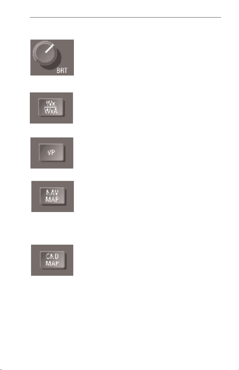
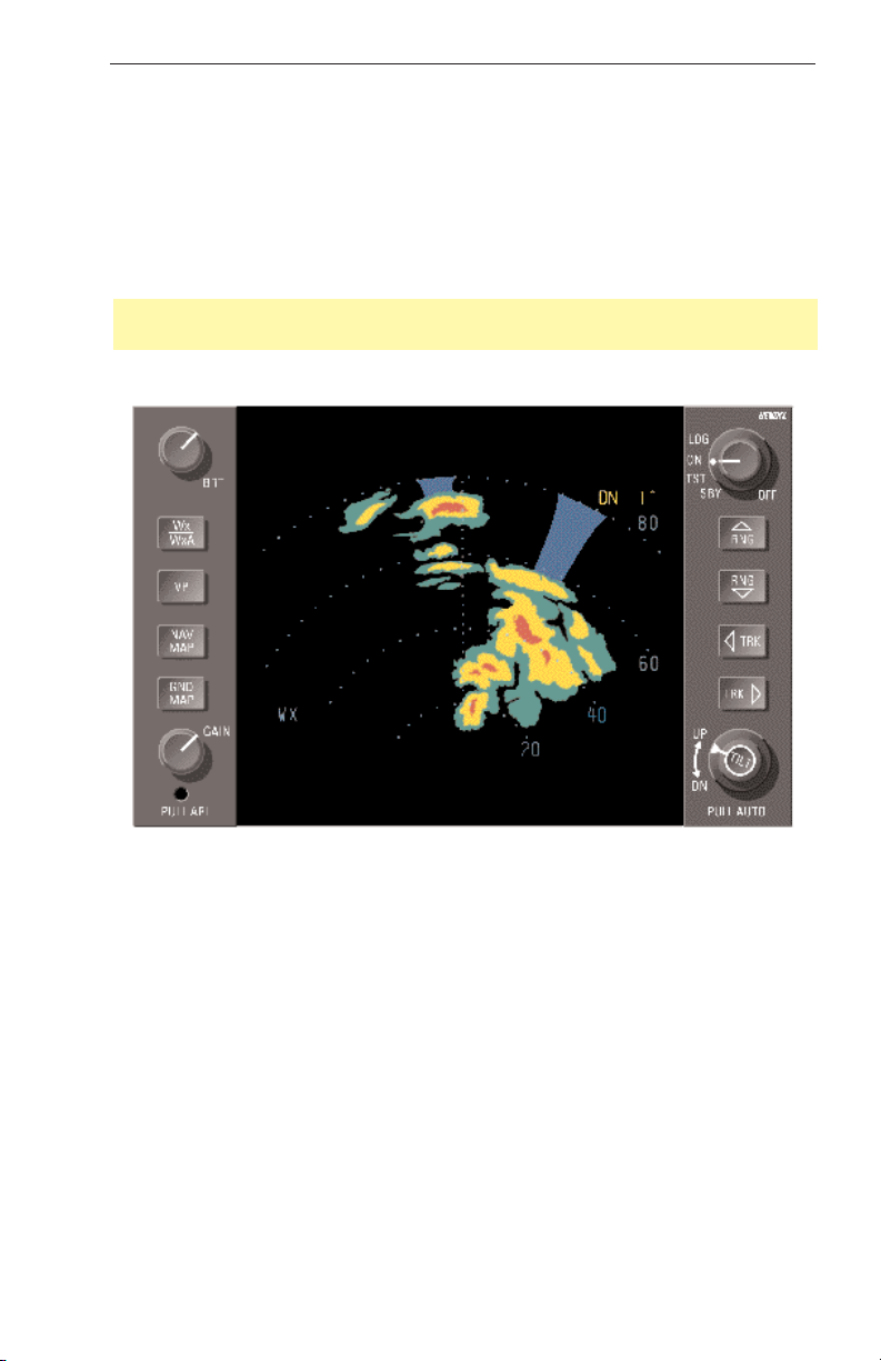
BRT - Controls brightness of the indicator display (CW
rotation for max brightness).
Wx/WxA - Alternately selects between the Wx
(weather) and WxA (weather-alert) modes of operation.
“Wx” or “WxA” will appear in the lower left of the display. Wx or WxA colors are: Black for no returns, Green
for weak returns, Yellow for moderate returns, Red for
heavy returns and Magenta for intense returns. When
the WxA mode is selected, magenta areas of storms
flash between magenta and black at a 1 HZ rate.
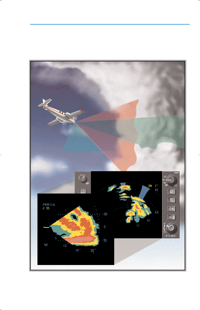
VP - Selects and deselects the Vertical Profile mode of
operation. When VP is selected on the indicator the
radar will provide a vertical scan of ±30 degrees at the
location of the horizontal track line. Selecting the VP
mode of operation will not change the selected mode of
operation: TST, Wx, WxA or GND MAP. Once in VP,
these modes may be changed as desired. VP will
engage from the NAV MAP mode, but NAV data will not
be displayed during VP operation.
NAV MAP - Places indicator in navigation mode so
that preprogrammed waypoints may be displayed. If
other modes are also selected, the NAV display will be
superimposed on them. This button is effective only if
an optional radar graphics unit and Flight Management
System is installed. If activated without these units, NO
NAV will appear at lower left of screen. The radar will
display weather when NAV MAP is selected if the radar
selector is in the ON position.
GND MAP - Places the radar system in ground mapping mode. Gain control capability is configurable at
installation to be enabled or disabled in ground map
mode. Ground map colors are: green for weak returns,
yellow for moderate returns and magenta for intense
returns. “MAP” will appear on the lower left of the display.
Effective Date: 9/98 RDR 2100 Pilot's Guide: Rev 1
1
Operational Controls
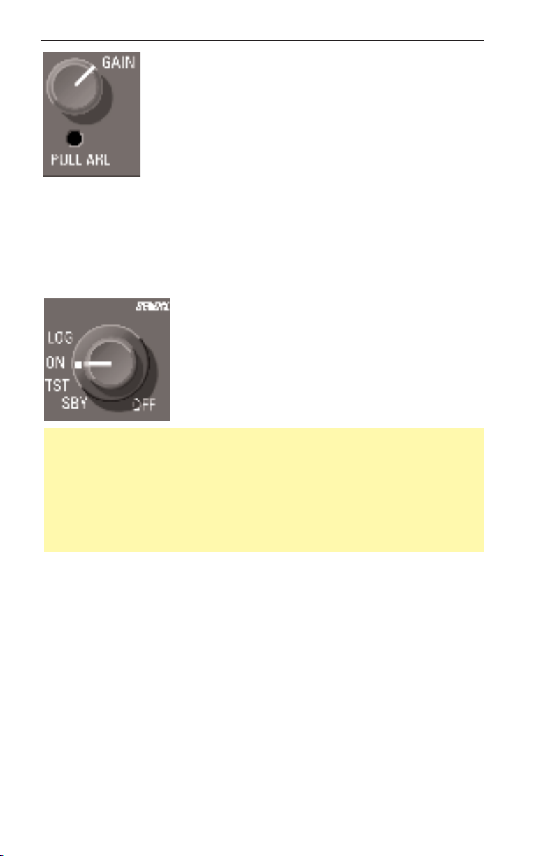
GAIN - The gain knob adjusts the radar gain from 0 to
-20 dB (CCW rotation reduces gain). The gain knob will
only function when in the MAP mode.
PULL ARL - (Automatic Range Limiting) - Displays a
blue area behind weather systems where weather
detection is no longer possible because of attenuation.
LOG - Used when Bendix/King radar graphics units are installed. A
listing of the latitudes and longitudes of selected waypoints are displayed. When a compatible navigation source is installed, the selected
VOR frequencies along with bearings and distances are also displayed.
The radar transmits in the LOG mode, unless a Bendix/King radar
graphics unit (IU-2023, GC-360A or GC-381A) is installed.
ON - Selects the normal condition of operation for
weather detection and/or other modes of opera-
tion. The system will transmit after a 60 second
warm-up time is completed. The radar system ini-
tializes to the Wx mode, 80 nm.
Note: The 60 second warm up period can be monitored upon power up
of the system. When the knob is switched directly from OFF to ON mode
(or LOG mode with no Bendix/King radar graphics unit installed), the display will blank. As the radar sweeps the blue/white will grow outward.
Just before the warm up period is complete, the screen will turn black for
a few seconds, then the radar will begin transmitting and the screen will
display radar returns. No radar transmissions occur until the warm up
period is complete.
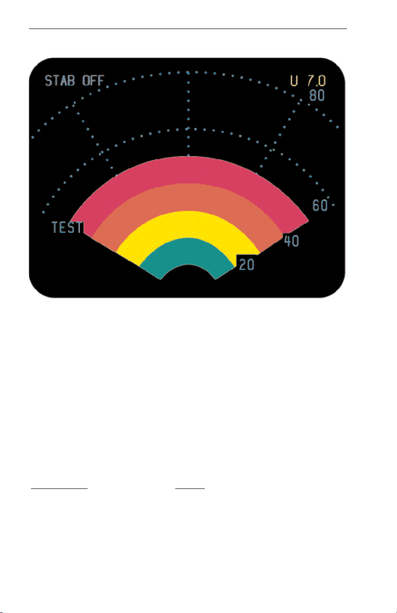
TST - The multicolored arc display test pattern is displayed in this mode
of operation. The test pattern (typical 4-color test pattern on page 4) is
initialized and sized to fit the 80 nm range and can also be scaled with
the range select buttons. No radar transmissions occur while TST is
selected. TEST will appear in the lower left of the display.
STAB OFF is always displayed in top left.
SBY - Fully energizes the system circuitry but no radar transmissions occur
in the SBY mode of operation. The antenna is parked at 0 degrees azimuth
and 30 degrees tilt down with the antenna drive motors locked. In the
standby mode of operation, NAV MAP, checklist and TCAS traffic can be
activated with a Bendix/King radar graphics unit (IU-2023B, GC-360A,
GC-362A or GC-381A) installed. SBY will appear in the lower left of the display.
Effective Date: 9/98
2
RDR 2100 Pilot's Guide: Rev 1
Operational Controls
OFF - Removes primary power from the radar indicator, but the radar
still has power applied. The radar will remain active with no radar transmissions occurring, for up to a maximum time of 30 seconds. This time
delay allows time to park the antenna at 0 degrees azimuth and 30
degrees tilt down.
Note: The only way to remove primary power from the radar is to pull
the radar circuit breaker.
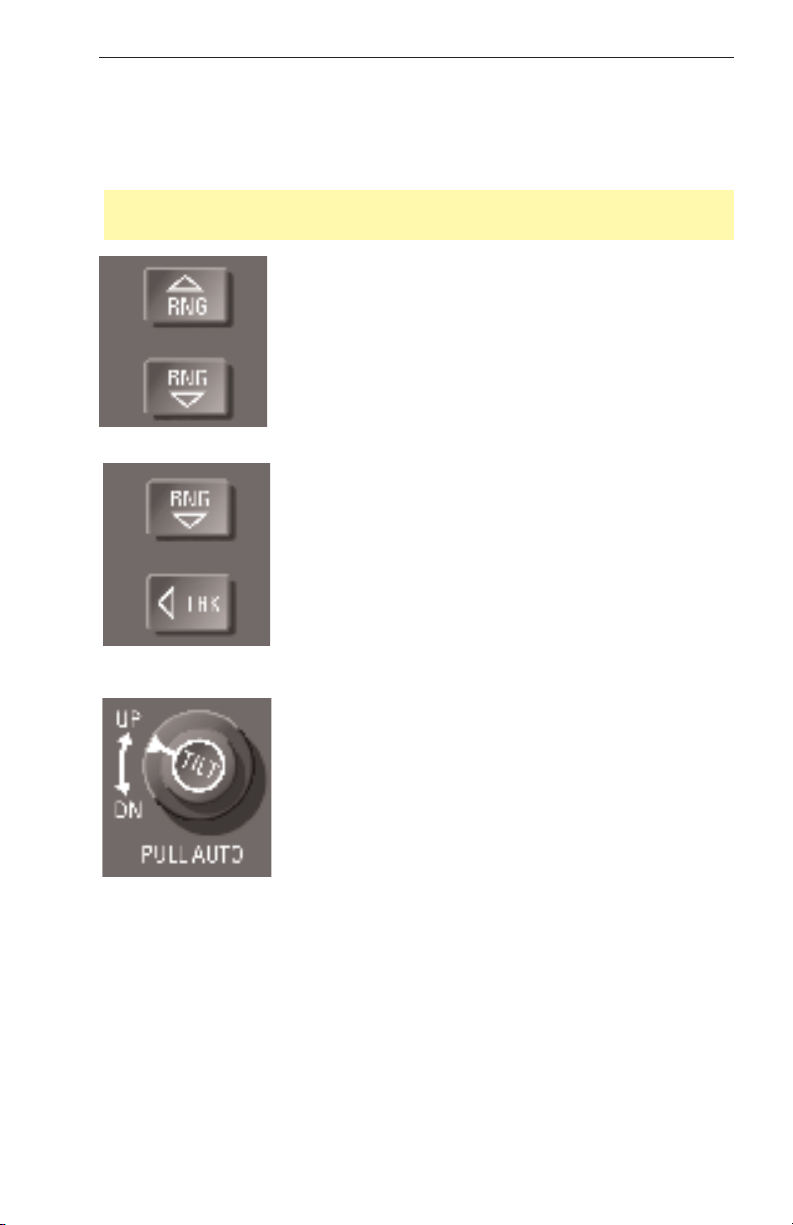
RNG - Clears the display and advances the indicator to the next range. The upper button increases
range, the lower button decreases it. The
RDR 2100 display ranges are: 5, 10, 20, 40, 80,
160, 240, 320 nm. The selected range is displayed
in the upper right corner of the display with the
range ring distance displayed along the right edge.
TRK - Provides a yellow track centerline for vertical
profile. With the radar on and a track button
pushed, the track line position moves left or right in
1 degree increments at a rate of about 15 degrees
per second. When Vertical Profile mode is selected,
the antenna scans the slice at the track line azimuth
position. While in Vertical Profile mode, the TRK
buttons move the slice left and right. The azimuth
position of the antenna is displayed on the upper
left corner of the indicator.
TILT - Permits manual adjustment of antenna tilt
15° up or down for best indicator presentation. The
tilt angle is displayed in the upper right corner of the
display.
PULL AUTO - Allows the antenna position to be
automatically adjusted to maintain a common beam
intercept point with the earth e.g. if the last 10% of
the display is ground returns, then during ascent or
decent the antenna tilt is automatically changed to maintain ground
returns on 10% of the display.
Effective Date: 9/98 RDR 2100 Pilot's Guide: Rev 1
3
Operational Controls
TEST PATTERN
FAULT ANNUNCIATIONS
Fault annunciations are a method of alerting the pilot that the radar
system is not performing to established standards. Built-in test equipment (BITE) automatically and constantly tests the radar system. If a
fault occurs, the fault annunciation will be presented on the Display unit.
There are two general categories of faults: hard failures and soft
failure/annunciations. By careful observation of the Display, you can
quickly evaluate the condition of the ART 2100.
Hard failures are those which occur when a major function of the system
is lost. Hard failures are typically a total loss of transmitter power,
receiver gain or no antenna scan. Turn off system. Should the system
be left on, further damage to other system components could occur.
Hard Failures:
Annunciation Failure
TX FLT Transmitter failure
429 FLT Loss of 429 bus data
ANT FLT Loss of antenna position
IN FLT 6 Loss of communication between
display and ART
Effective Date: 9/98
4
RDR 2100 Pilot's Guide: Rev 1

Preflight
Note: A TX FLT is indicated if the Strut switch is configured to be active
and the aircraft is on the ground.
Soft failures are those which can cause limited system operation, Radar
data will still be displayed but the flight crew should be aware that the
display does not necessarily represent the true weather. Soft failures
are typically configuration problem, stabilization problems, or some similar problem.
Soft Failures:
Annunciation Cause
TX FLT alternating with ANT FLT Configuration module not
being read
STAB LMT Stab. Is exceeding ±30˚
STAB OFF Alert that the scan is not being
stabilized
PREFLIGHT
PREFLIGHT WARNINGS
Do not turn the radar on within 5 feet of containers of flammable or
explosive material. The radar should never be operated during fueling.
Do not attempt to operate the radar until you are completely familiar
with all safety information, including that on pages 62 through 65.
The system always transmits in the ON mode, unless the aircraft is on
the ground and the radar is interfaced to the strut switch. The radar
transmits in LOG mode if the radar is not interfaced to a Bendix/King
radar graphics unit. The system never transmits in the OFF, SBY or TST
modes.
Accomplish the following procedures completely and exactly.
1) Place the radar controls in the following positions:
• Function switch to TST
• Tilt to UP 7 (as shown on the indicator display, upper right corner).
The test pattern will appear. See that the test pattern conforms to the
illustration (The test pattern is sized to fit the 80 nm range and can be
scaled with the range buttons), and observe the “update” action as a
small ripple moves across the display along the outer edge.
Effective Date: 9/98 RDR 2100 Pilot's Guide: Rev 1
5

Preflight
2) With the function switch in TST or SBY, taxi to a clear area where
there are no people, aircraft, vehicles, or metallic buildings within
approximately 100 yards.
3) Rotate the function switch to ON. The indicator will automatically display in the Wx mode and 80 nm range. Any targets (weather or
ground) will be displayed in green, yellow, red, or magenta. (Note: A
60 second warm up time period is required before the system will
transmit).
4) Press the range-down button to display 40 nm as the maximum range.
5) Press the WxA button and observe that magenta areas (if any) flash.
6) Vary the tilt control manually between 0 and up 15 degrees and
observe that close-in “ground clutter” appears at lower settings and
that any local rain appears at higher settings.
7) Repeat the manual tilt adjustment, this time between the 0 and down
15 degrees positions.
8) Return the function switch to TST or SBY before taxiing!
9) When you are ready for weather detection (after takeoff or just
before), place the function switch to ON and operate the system as
described in the Operation In-Flight section.
Effective Date: 9/98
6
RDR 2100 Pilot's Guide: Rev 1
Theory of Operation
THEORY OF OPERATION
GENERAL
The primary use of this radar is to aid the pilot in avoiding thunderstorms
and associated turbulence. Since each operator normally develops specific operational procedures for use of weather avoidance radar, the following information is presented for use at the operator’s discretion.
Operational techniques for the RDR 2100 are similar to earlier generation weather avoidance radars. The proficient operator manages
antenna tilt control to achieve best knowledge of storm height, size, and
relative direction of movement.
RADAR PRINCIPLES
Radar is fundamentally a distance measuring system using the principle
of radio echoing. The term RADAR is an acronym for RAdio Detecting
and Ranging. It is a method for locating targets by using radio waves.
The transmitter generates microwave energy in the form of pulses.
These pulses are then transferred to the antenna where they are focused
into a beam by the antenna. The radar beam is much like the beam of
flashlight. The energy is focused and radiated by the antenna in such a
way that it is most intense in the center of the beam with decreasing
intensity near the edge. The same antenna is used for both transmitting
and receiving. When a pulse intercepts a target, the energy is reflected
as an echo, or return signal, back to the antenna. From the antenna, the
returned signal is transferred to the receiver and processing circuits
located in the receiver transmitter unit. The echoes, or returned signals,
are displayed on an indicator.
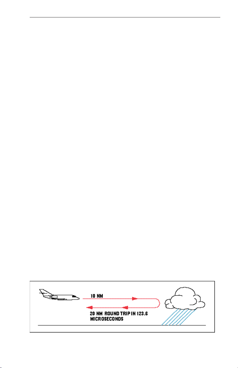
Radio waves travel at the speed of 300 million meters per second and
thus yield nearly instantaneous information when echoing back. Radar
ranging is a two-way process that requires 12.36 micro-seconds for the
radio wave to travel out and back for each nautical mile of target range.
As shown in the distance illustration below, it takes 123.6 micro-seconds
for a transmitted pulse of radar energy to travel out and back from an
area of precipitation 10 nautical miles away.
Effective Date: 9/98 RDR 2100 Pilot's Guide: Rev 1
7
Theory of Operation
WEATHER RADAR PRINCIPLES
Airborne weather avoidance radar, as its name implies, is for avoiding
severe weather, not for penetrating it. Whether to fly into an area of
radar echoes depends on echo-intensity, spacing between the echoes,
aircraft capabilities and pilot experience. Remember that weather radar
detects only precipitation drops; it does not detect minute cloud droplets,
nor does it detect turbulence. Therefore, the radar provides no assurance of avoiding instrument weather in clouds and fog. The indicator
may be clear between intense echoes; this clear area does not necessarily mean it is safe to fly between the storms and maintain visual
sighting of them.
The geometry of the weather radar radiated beam precludes its use for
reliable proximity warning or anti-collision protection. The beam is characterized as a cone shaped pencil beam. It is much like that of a flashlight or spotlight beam. It would be an event of chance, not of certainty,
that such a beam would come upon another aircraft in flight.
Note: Weather avoidance radar is not practical as a pilot operable terrain or collision avoidance system. Weather analysis and avoidance are
the primary functions of the radar system.
RADAR BEAM ILLUMINATION
Probably the most important aspect of a weather radar is the antenna
beam illumination characteristic. To make a proper interpretation of what
you are seeing on the display, you must have an understanding of what
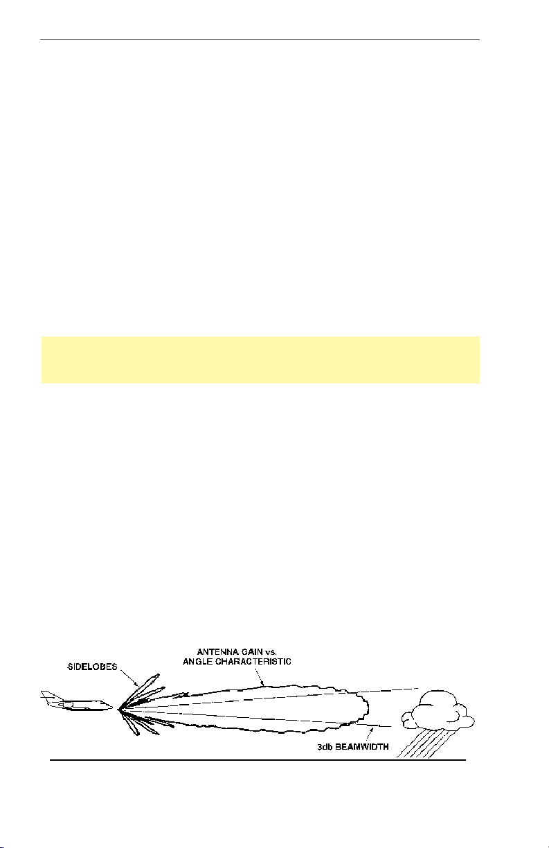
the radar beam “is seeing”. The following figure is a side view of the
radar beam characteristic with a storm depicted at a distance that causes
the size of the storm to just fill the 3 dB beamwidth. This would be the
typical situation for a storm at approximately 40 nautical miles with a 12
inch diameter antenna. It’s important to understand and visualize this situation, to enhance your understanding of the rest of this manual. First
some observations are in order:
Effective Date: 9/98
8
RDR 2100 Pilot's Guide: Rev 1

Theory of Operation
Note that the antenna gain versus angle characteristic is a continuous
function at all angles. This means that there is a gain value associated
with all forward angles relative to the selected tilt angle. In this figure the
tilt angle is shown as zero degrees. This means the beam center is
along the same angle as the aircraft flight angle. Next, the points on
either side of the beam where the antenna gain is down 3 dB relative to
the maximum gain defines the 3 dB beamwidth. The remainder of the
manual uses the cone shaped 3 dB beamwidth extensively to illustrate
how the beam spreads with distance, much like a flashlight beam. Also
important is the understanding that this angle is wider for smaller
antennas (10”) and narrower for larger antennas. It’s also important to
realize that the antenna gain does not go to zero outside the 3 dB
beamwidth, it just continues to reduce with increasing angles. This is
what it meant by a continuous gain function. This understanding is
important when we discuss ground clutter reflections later.
Also note that there are small lobes of the gain characteristic at fairly
large angles. These are called sidelobes. Generally these are not
important since the gain value for these lobes is down 25 or more dB
from the peak. However a bad radome can increase these sidelobes to
a point that they cause a constant radar reflection from the ground. This
is commonly referred to as an “altitude ring” because the display will
show a concentric ring at a distance equal to the slant range of the sidelobe to the ground.
The cone formed by the 3 dB beamwidth is where most of the radar
energy is concentrated, so it is important to realize that at any given time
whatever is within this cone (and sometimes other strong targets like
clutter outside the cone) is what is being painted on the display. The
pilot should be aware of how wide this cone is as a function of range.
The primary target of interest is obviously weather cells of significance.
The typical cell is considered to be 3 nm in diameter. It is mandatory that
the beam be pointed at the wet part of the weather cell to record the
proper rainfall intensity (color level). To aid the pilot at accomplishing this
task, the “Radar Beam Diagram” tool is provided. This tool is a transparent 3 dB beamwidth overlay for each antenna size and range scales
of 40, 80, and 160 nm in length, each of which has multiple weather cells
shown to scale at different distances. A user can position the overlay on
a given target and read the tilt angle that will position the beam at the
“below freezing” part of the cell. This tool should be understood and kept
handy when trying to interpret the weather display.This tool illustrates
that at greater distances, the weather cell doesn’t fill the cone shaped
beam. Under these conditions the distinction of the weather cell from the
ground clutter is most difficult. The following figure illustrates this condition.
Effective Date: 9/98 RDR 2100 Pilot's Guide: Rev 1
9
Theory of Operation
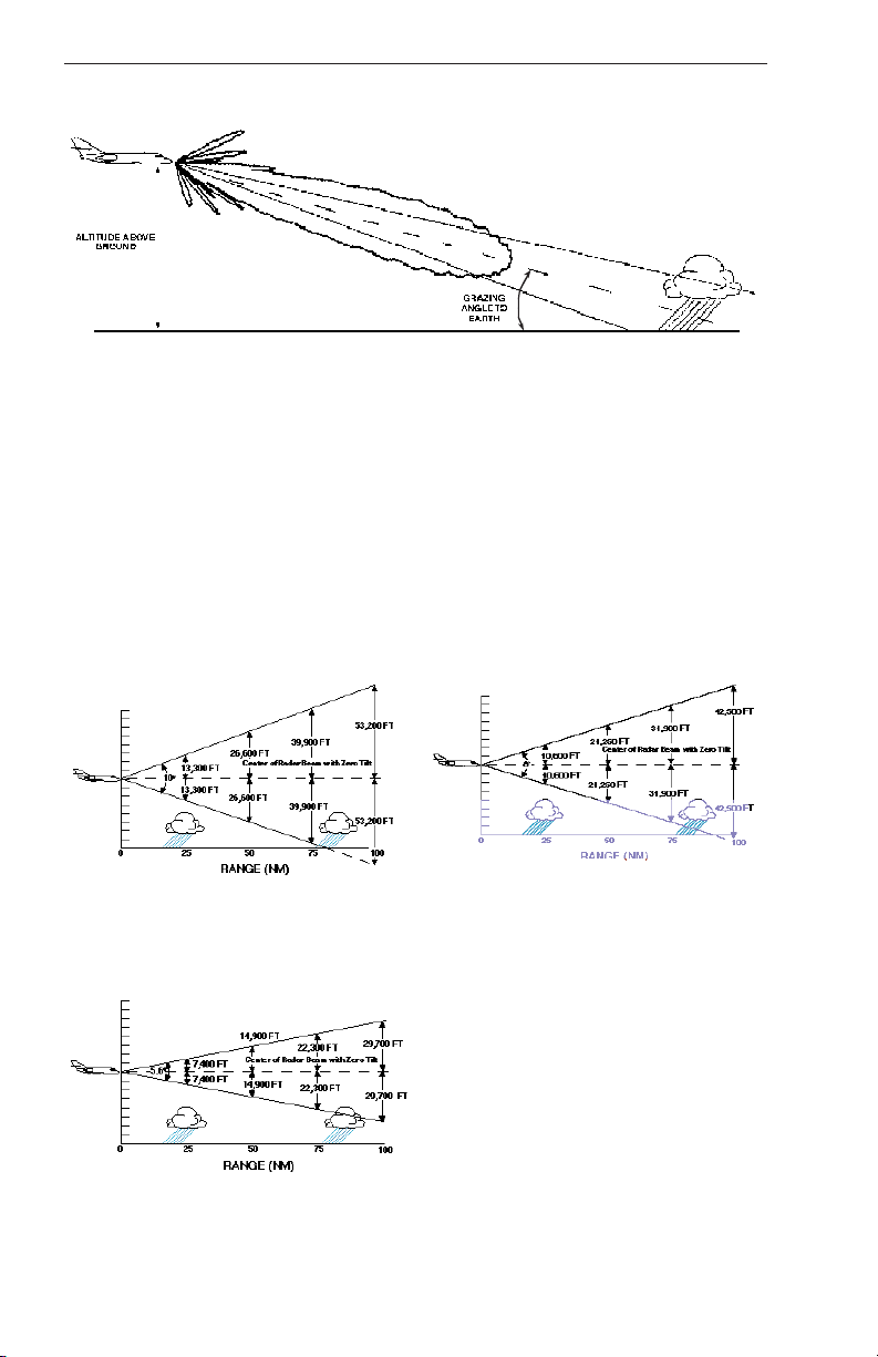
In this scenario the weather cell might be at 100 nm, the altitude might
be 40,000 feet, and the appropriate tilt angle is approximately -3
degrees. Notice that the beam is centered on the rain but it also intersects the ground. The angle the beam makes with the ground is called
the grazing angle. When this angle gets greater than about 2 degrees
the ground reflections that return to the radar become very significant. A
later section called “Tilt Management” discusses this difficult topic and
makes some suggestions to help make weather/ground distinction.
The following diagrams show the beam width relationship with 10 inch,
12 inch and 18 inch antennas. For illustrative purposes the aircraft are
shown at approximately 40,000 feet and the tilt is set at zero degrees.
Radar Beam Illumination
with 10 Inch Antenna
Radar Beam Illumination
with 18 Inch Antenna
Effective Date: 9/98
Radar Beam Illumination
with 12 Inch Antenna
10
RDR 2100 Pilot's Guide: Rev 1
Theory of Operation
RADAR REFLECTIVITY
What target will reflect the radar’s pulses and thus be displayed on the
indicator? Only precipitation (or objects more dense than water such as
earth or solid structures) will be detected by an X-band weather radar.
Therefore weather radar does not detect clouds, thunderstorms or turbulence directly. Instead, it detects precipitation which may be associated
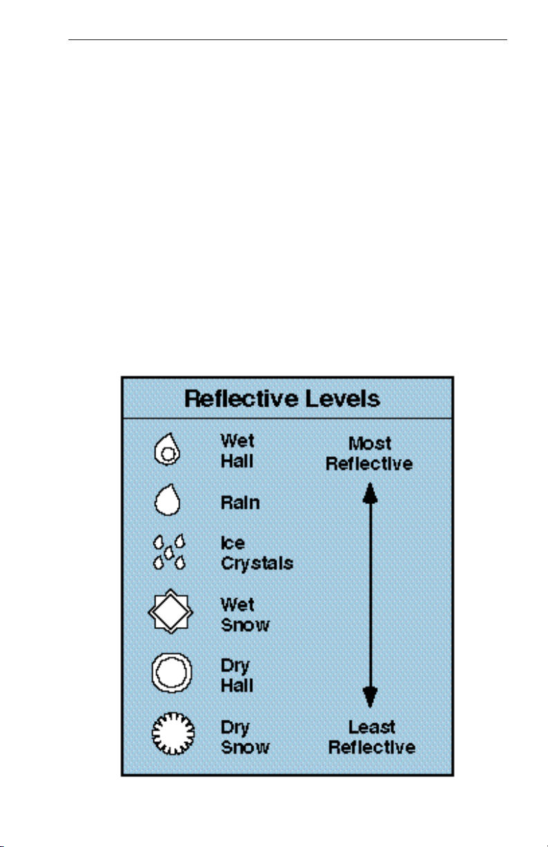
with dangerous thunderstorms and turbulence. The best radar reflectors
are raindrops and wet snow or hail. The larger the raindrop the better it
reflects. Because large drops in a small concentrated area are characteristic of a severe thunderstorm, the radar displays the storm as a
strong echo. Drop size is the most important factor in high radar reflectivity. Generally, ice, dry snow, and dry hail have low reflective levels
and often will not be displayed by the radar.
A cloud that contains only small raindrops, such as fog or drizzle, will not
produce a measurable radar echo. But if the conditions should change
and the cloud begins to produce rain, it will be displayed on radar.
Effective Date: 9/98 RDR 2100 Pilot's Guide: Rev 1
11
Theory of Operation
WEATHER DISPLAY CALIBRATION
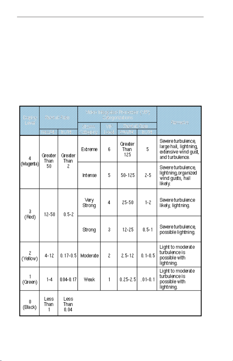
The radar display has been calibrated to show five levels of target intensity: Black (level 0), Green (level 1), Yellow (level 2), Red (level 3), and
Magenta (level 4). The meaning of these levels is shown in the following
chart as to their approximate relationship to the Video Integration
Processor (VIP) intensity levels used by the National Weather Service.
These levels are valid only when; (1) the Wx and WxA mode are
selected; (2) the displayed returns are within the STC range of the radar
(approximately 40 miles); (3) the returns are beam filling; (4) there are no
intervening radar returns.
Radar Display and Thunderstorm Levels
Effective Date: 9/98
Versus Rainfall Rates
12
RDR 2100 Pilot's Guide: Rev 1

Theory of Operation
WEATHER ATTENUATION COMPENSATION
An extremely important phenomena for the weather avoidance radar
operator to understand is that of attenuation. When a radar pulse is transmitted into the atmosphere, it is progressively absorbed and scattered so
that it loses its ability to return to the antenna. This attenuation or weakening of the radar pulse is caused by two primary sources, distance and
precipitation. The RDR 2100 has several advanced features which significantly reduce the effects of attenuation (no airborne weather radar can
eliminate them completely). It is therefore up to the operator to understand the radar’s limitations in dealing with attenuation.
Attenuation because of distance is due to the fact that the radar energy
leaving the antenna is inversely proportional to the square of the distance.
For example, the reflected radar energy from a target 60 miles away will
be one fourth (if the target is beam filling) of the reflected energy from an
equivalent target 30 miles away. The displayed effect to the pilot is that
as the storm is approached, it will appear to be gaining in intensity. To
compensate for distance attenuation both Sensitivity Timing Control
(STC) and Extended STC circuitry are employed. The RDR 2100 has an
STC range of 0 to approximately 40 nautical miles. Additionally, the
radar will electronically compensate for the effects of distance attenuation
with the net effect that targets do not appear to change color as the distance decreases.
Outside the STC range the Extended STC circuitry increases the displayed intensity to more accurately represent storm intensity. The
Extended STC will not, however, totally compensate for distance attenuation and, therefore, targets in this range can be expected to show more
detail as the distance decreases until reaching the STC range.
Attenuation due to precipitation is far more intense and is less predictable
than attenuation due to distance. As the radar pulses pass through moisture, some radar energy is reflected. But much of that energy is
absorbed. If the rain is very heavy or extends for many miles, the beam
may not reach completely through the area of precipitation. The weather
radar has no way of knowing if the beam has been fully attenuated or has
reached the far side of the precipitation area. If this beam has been fully
attenuated the radar will display a “radar shadow” which appears as an
end to the precipitation when, in fact, the heavy rain may extend for many
more miles. In the worst case, precipitation attenuation may cause the
area of heaviest precipitation to be displayed as the thinnest area of
heavy precipitation. It may cause one cell containing heavy precipitation
to totally block or shadow a second heavy cell located behind the first cell
and prevent it from being displayed on the radar. Never fly into radar
shadows and never believe that the full extent of heavy rain is being
seen on radar unless another cell or a ground target can be seen beyond
the heavy cell. Proper use of the antenna tilt control can help detect radar
shadows.
Effective Date: 9/98 RDR 2100 Pilot's Guide: Rev 1
13

Theory of Operation
Attenuation can also be a problem when flying in a large area of general
rain. If the rain is moderate, the radar beam may only reach 20 or 30
miles before it is fully attenuated.
The pilot may fly along for many miles seeing the same 20-30 nautical
miles of precipitation ahead on the radar when, actually, the rain may
extend a great distance. In order to aid in reducing the effects of precipitation attenuation, the RDR 2100 contains sophisticated weather attenuation compensation circuitry. The attenuation compensation feature is
totally automatic in the Wx/WxA mode of operation and requires no pilot
action to activate other than selecting Wx/WxA mode of operation. The
compensation logic operates between 3 to 320 nautical miles, whenever a
level 2 (yellow), 3 (red) or 4 (magenta) echo is displayed. The compensation circuits cause the software to measure each individual cell return
and increase each individual cell return independently while the antenna
scans the sector containing heavy rain. The compensation circuitry
allows the radar beam to effectively look deeper into and through heavy
rain to search for possible storm cells beyond. While attenuation compensation does not eliminate precipitation attenuation, it does allow the radar
to see through more rain at short ranges where every bit of weather information possible is needed. If there is suspicion that the radar is attenuating due to precipitation, exercise extreme caution and ask ATC what
they are showing. Often the ground based ATC controller’s radar will have
a better overall picture of a large rain area and the pilot can compare the
controller’s information with his own radar picture to avoid the strongest
cells in a general area of rain.
Effective Date: 9/98
14
RDR 2100 Pilot's Guide: Rev 1
Theory of Operation
AUTOMATIC RANGE LIMITING (ARL)
The RDR 2100 contains Automatic Range Limiting (ARL) circuitry which
causes the display to depict areas that the radar cannot penetrate due to
signal attenuation. Typically, the ARL display will show blue areas on the
far side of a series of severe weather systems. This cautions the pilot to
avoid flight into the blue areas due to the uncertainty of weather conditions.
Note: Radar shadows are shown in blue when ARL is active. NEVER
FLY INTO ARL BLUE RETURN AREAS.
Effective Date: 9/98 RDR 2100 Pilot's Guide: Rev 1
15

Theory of Operation
TARGET ALERT
The RDR 2100 system can be configured at installation to include the
Target Alert feature. The purpose of the feature is to alert the pilot to the
presence of a significant weather cell that exists beyond the currently
selected range. For this mode to be active, Wx or WxA mode must be
selected and Vertical Profile must not be selected. The criteria for a
Target Alert is for the cell to be at least red intensity, within ±10˚ of aircraft
heading, a minimum size of 2 NM in range and 2 degrees in azimuth, and
within the range of 80 to 320 NM. When a Target Alert is issued, two red
arcs, separated by a black arc will be displayed at the top of the display
centered on the aircraft heading (see the following figure). Target Alert is
applied to each scan independent of the other when the radar is alternating scans.
Note: Target Alert is not active in the ground map mode.
Effective Date: 9/98
16
RDR 2100 Pilot's Guide: Rev 1
Theory of Operation
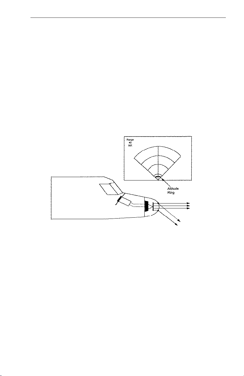
ALTITUDE RING (RANGE RING)
Not all radar transmitted energy is contained in the main beam radiation
pattern. Some of the energy is radiated in the side lobe pattern. The
characteristics of some radomes and/or nose caps can cause detrimental
side lobe radiation. Should this occur, the side lobe can be radiated down
toward the earth and the reflected energy received by the radar may be
displayed on the indicator as a narrow ring of video. When the indicator is
on the 10 or 20 nm range, this can be seen at a distance corresponding to
the altitude, typically one mile per 6000 feet. During “Wx” operation, when
this phenomenon occurs, no appreciable degradation of the radar to
depict weather exists. This phenomenon is largely dependent upon the
shape and physical condition of the radome or nose cap on the aircraft.
Effective Date: 9/98 RDR 2100 Pilot's Guide: Rev 1
17

Theory of Operation
RADOMES
A radome is a covering that shields the radar antenna from hostile environments, such as fast moving air, rain, bugs, and ice. It allows the
microwave energy to pass through relatively undisturbed. This means
that very little of the microwave energy passing through it will be
absorbed, reflected, or redirected as a result of it’s presence. Some
radomes closely approximate this definition, while others do not.
Here are some faults which can occur in radomes:
1. A pitted honeycomb radome can result from being struck by high
velocity projectiles, such as rain, ice, sand, bugs, etc. Once the
surface integrity has been broken, water intrusion can occur and
cause significant radar signal loss.
2. A poorly sealed plastic radome nose boot which has allowed
moisture to be trapped behind it.
3. Paint containing metallic particles mistakenly applied to all or part
of the radome.
4. An improperly fabricated fiberglass radome.
5. A poorly repaired “ding” on the radome.
6. An object, usually metallic, located inside the radome and in the
path of part of the transmitted microwave energy.
As a result of items 5 and 6 above, a “phantom ring” may appear on the
radar display. Normally the cause is an obstruction in the bottom of the
radome. This obstruction can cause some of the radiated energy to be
directed down to the ground instead of in the forward direction.
Reflective material in the top of the radome can result in the same situation. In either case, energy returns from the same direction that it was
transmitted causing an “altitude ring” to be presented on the radar display. It is called an altitude ring because it moves in and out as the aircraft changes altitude.
Items 1, 2, 3, and 4 can result in radar performance problems while
checking out as “no trouble found” at the repair center. The radome is
blocking too much energy.
Care must be exercised to be sure that only qualified personnel perform
repairs on the radome. Also, it is time well spent during preflight to
include checking the radome to be sure it remains in good repair. When
examining the radome, be certain the radar is not transmitting
microwave energy. See MPEL (Maximum Permissible Exposure Levels)
in the Appendix.
Effective Date: 9/98
18
RDR 2100 Pilot's Guide: Rev 1

Weather Mapping and Interpretation
WEATHER MAPPING AND INTERPRETATION
This section contains general information on use of radar for weather
interpretation. Review of this information will assist the operator in using
radar.
Note: The ability of a weather radar system to display weather returns is
dependent upon the radome Transmission Efficiency. Bendix/King recommends a 90% average/85% minimum transmission efficiency. Refer
to RTCA document DO-213 Class A for minimum operational performance standards for nose mounted radomes.
OBSERVING WEATHER
A weather avoidance radar is only as good as the operator’s interpretation of the echoes that are displayed on the radar indicator. The operator
must combine knowledge of how radar works and its limitations with
such things as the prevailing weather pattern, and geographic location in
order to make a sound interpretation of the displayed targets.
As a starting point the operator should read FAA Advisory Circular
number 00-24B (Subject: Thunderstorms). It is also highly recommended
that the operator take advantage of one of the commercially available
weather radar seminars.
Effective Date: 9/98 RDR 2100 Pilot's Guide: Rev 1
19
 Loading...