


SG 465
Table of contents
 Loading...
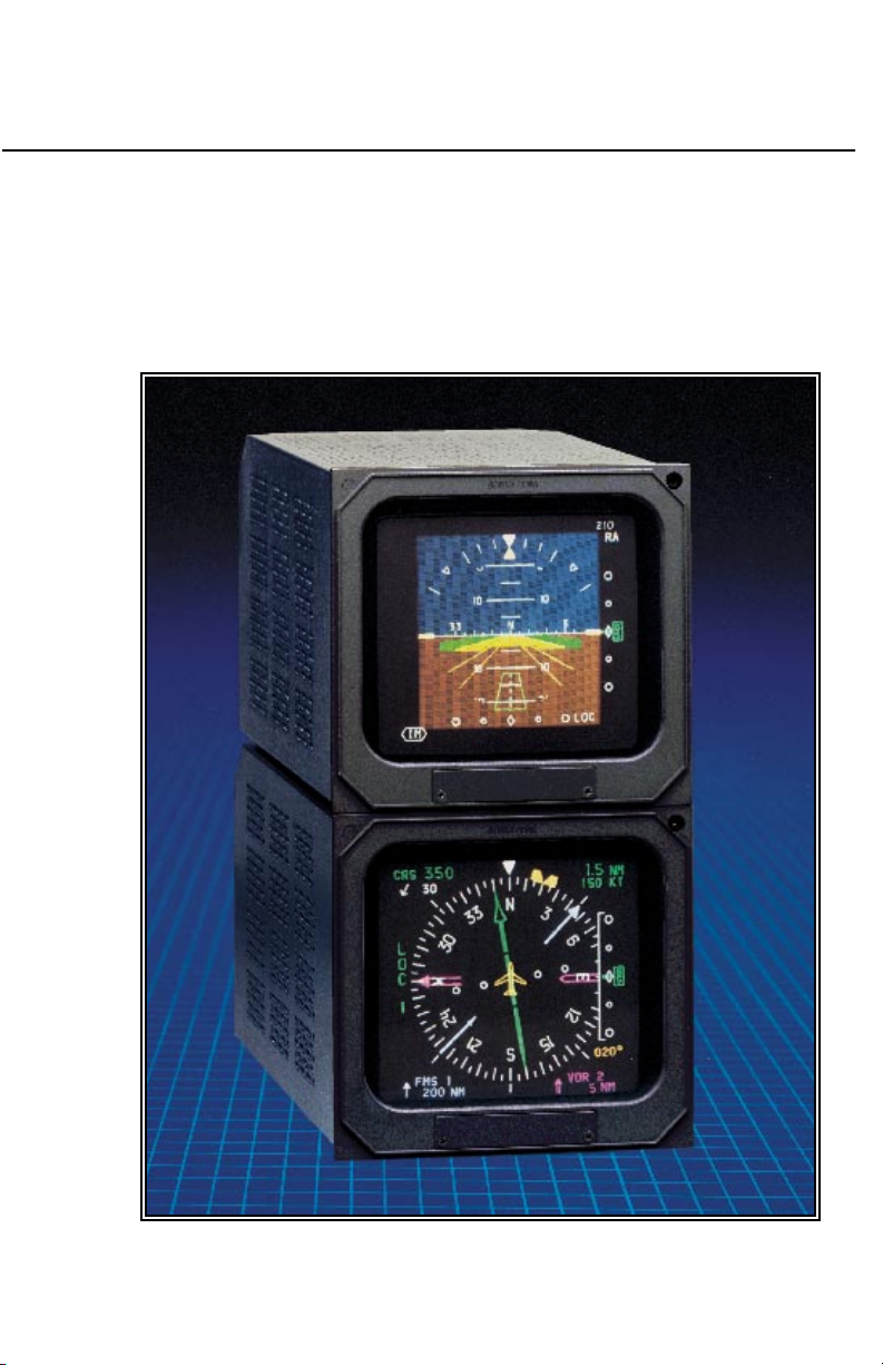
EFS 50
Pilot’s Guide
5-inch Electronic Flight
Instrumentation System
AA

Registration
This pilot's guide has been tailored by the installation and or certification agency to cover the following EFS 50 installation:
AIRCRAFT TYPE
AIRCRAFT TAIL OR SERIAL NUMBER
AIRCRAFT OWNER
EFIS TYPE
EFIS SYSTEM CONFIGURATION
EFIS SYSTEM SOFTWARE LEVEL
EFIS DISPLAY UNIT TYPE
EFIS CONTROL PANELS
REVERSIONARY MODES
Throughout this pilot's guide various configuration options are
described. A ✔❏ (check box) precedes each configuration option. A
check mark may be placed in the appropriate boxes to define which
configuration options are available in a given installation.

Registration

Table of Contents
TABLE OF CONTENTS
Section I
INTRODUCTION I.1
Section 1
SYSTEM CONFIGURATION 1.1
GENERAL 1.1
CONTROL DISPLAY 1.1
CONTROL DISPLAY OPTIONS 1.3
SYMBOL GENERATOR 1.3
EQUIPMENT INTERFACE & OPERATING CONFIGURATION 1.5
SOFTWARE 06 CONFIGURATION PAGES 1.6
SOFTWARE 07 CONFIGURATION PAGES
(includes both 0701 and 0702) 1.10
SOFTWARE 08 CONFIGURATION PAGES 1.14
SOFTWARE 11 CONFIGURATION PAGES 1.18
Section 2
EHSI OPERATION 2.1.1
Detailed Operating Controls 2.1.1
EHSI Controls (CP 467) 2.1.3
HSI 360-DEGREE MODE SELECTION 2.1.3
ARC SECTORED MODE SELECTION 2.1.3
NAV NAVIGATION SENSOR SELECT 2.1.4
1-2 NAVIGATION SYSTEM SELECT 2.1.6
BEARING POINTER SELECT 2.1.6
RANGE SELECTION 2.1.7
TST/REF 2.1.8
TST - 2.1.8
REF GROUND SPEED or TIME-TO-STATION selection 2.1.8
REF MAP FORMAT 2.1.9
COURSE SELECT KNOB 2.1.10
HEADING SELECT KNOB 2.1.10
DISPLAY BRIGHTNESS CONTROL 2.1.10
EADI OPERATION 2.2.1
EADI Detailed Operating Controls 2.2.1
BRIGHTNESS 2.2.1
DH SET 2.2.1
RALT TST 2.2.2
Issued 4/95
SW 06/07/08/11
TOC.1

Table of Contents
RADAR OPERATION 2.3.1
Radar Controls, (CP 466A & CP 466B) 2.3.3
OFF-STBY-TST-ON 2.3.4
OFF 2.3.4
STBY 2.3.4
TST 2.3.4
ON 2.3.4
WX 2.3.4
WXA 2.3.4
GND MAP 2.3.4
LIGHTNING 2.3.5
VP 2.3.5
TRK 2.3.6
GAIN 2.3.7
PULL ARL 2.3.7
TILT 2.3.7
MFD OPERATION 2.4.1
Multi Function Display Control Panel 2.4.1
Control Panel Button Operations 2.4.2
TCAS ONLY BUTTON 2.4.2
HSI BUTTON 2.4.2
ARC BUTTON 2.4.2
ENT BUTTON 2.4.2
LNAV MAP 2.4.2
PLAN-VIEW MAP (available with software 07) 2.4.2
CHECKLIST (available with software 08) 2.4.2
NAV BUTTON 2.4.3
RANGE UP/DOWN BUTTONS 2.4.3
CHECKLIST BUTTON 2.4.3
COURSE SELECT KNOB/BUTTON 2.4.3
BEARING #1 & #2 BUTTON 2.4.4
JOYSTICK 2.4.4
LNAV MAP 2.4.4
PLAN-VIEW MAP 2.4.5
CHECKLIST MODE (available with software 08) 2.4.6
1-2 BUTTON 2.4.6
TST/REF BUTTON 2.4.7
Section 3
ABBREVIATED OPERATIONS 3.1
TOC.2
SW 06/07/08/11
Issued 4/95

Table of Contents
Section 4
EHSI DISPLAYS 4.1.1
EFS 50 Color Standards 4.1.1
Standard EHSI Displays 4.1.1
NORMAL COMPASS CARD 4.1.1
NAVIGATION SOURCE ANNUNCIATION 4.1.2
SYMBOLIC AIRCRAFT 4.1.3
HEADING SELECT “BUG” 4.1.3
COURSE SELECT 4.1.3
LATERAL COURSE DEVIATION SCALE 4.1.4
LATERAL COURSE DEVIATION BAR 4.1.4
TO/FROM INDICATOR 4.1.5
DISTANCE, GROUNDSPEED and TIME-TO-STATION 4.1.5
DUAL MULTI CHANNEL DME INSTALLATION 4.1.6
DME HOLD 4.1.7
BEARING POINTER 4.1.8
MAGNETIC/TRUE HEADING ANNUNCIATIONS 4.1.10
GLIDE SLOPE/VERTICAL NAVIGATION 4.1.10
WIND VECTOR 4.1.12
DRIFT ANGLE POINTER (LNAV only) 4.1.12
LNAV MODE ANNUNCIATIONS 4.1.12
360 Map Displays 4.1.13
MAP 360 COMPASS CARD 4.1.13
SELECTED COURSE 4.1.13
MAP COURSE DEVIATION INDICATOR 4.1.14
TO/FROM 4.1.14
BEARING POINTER 4.1.14
REFERENCE WAYPOINT 4.1.15
RANGE RING 4.1.16
360-DEGREE MAP WX RADAR (IF EQUIPPED) 4.1.16
TRACK LINE 4.1.17
LIGHTNING DETECTION 4.1.17
FULL TIME LNAV MAP 4.1.18
ARC (Expanded Sectored Mode) Displays 4.1.20
HDG BUG (ALL ARC FORMAT MODES) 4.1.20
COURSE DEVIATION INDICATOR 4.1.20
(EHSI ARC NON-MAP FORMAT)
EADI DISPLAYS 4.2.1
Normal Attitude Display 4.2.1
PITCH ATTITUDE 4.2.1
ROLL ATTITUDE 4.2.1
ROLL INDICATOR 4.2.1
Issued 4/95
SW 06/07/08/11
TOC.3

Table of Contents
PERSPECTIVE LINES 4.2.2
SYMBOLIC AIRCRAFT 4.2.2
HEADING TAPE 4.2.2
FLIGHT DIRECTOR COMMAND BARS 4.2.3
AUTOPILOT/FLIGHT DIRECTOR MODE ANNUNCIATION 4.2.3
STANDARD 429 AUTOPILOT/FLIGHT 4.2.3
DIRECTOR MODE ANNUNCIATION
RADIO ALTIMETER 4.2.5
DECISION HEIGHT SET 4.2.6
DECISION HEIGHT ALERT 4.2.6
PRECISION APPROACH MODE FORMAT 4.2.6
EXPANDED LATERAL DEVIATION SCALE 4.2.6
RISING RUNWAY 4.2.7
GLIDESLOPE/VERTICAL NAVIGATION 4.2.8
MARKER BEACON ANNUNCIATION 4.2.8
FAST/SLOW 4.2.8
RATE OF TURN DISPLAY 4.2.9
CATEGORY II ANNUNCIATOR 4.2.9
CATEGORY II OPERATION ANNUNCIATIONS 4.2.9
CATEGORY II THRESHOLDS 4.2.11
ATTITUDE MONITOR 4.2.12
CROSS COMPARATOR ANNUNCIATORS 4.2.12
RA 4.2.12
LOC 4.2.12
GS 4.2.12
ATT 4.2.12
HDG 4.2.13
COMPOSITE DISPLAYS 4.3.1
COMPOSITE MODE 4.3.1
HEADING TAPE 4.3.1
SELECTED COURSE 4.3.1
HEADING BUG SELECT 4.3.1
NAVIGATION SOURCE ANNUNCIATION 4.3.2
LATERAL COURSE DEVIATION SCALE 4.3.2
(Non Approach Mode)
LATERAL COURSE DEVIATION BAR 4.3.2
TO/FROM 4.3.3
DISTANCE INFORMATION 4.3.3
DME HOLD 4.3.3
MFD DISPLAYS 4.4.1
CRS , CRS NOT SELECT 4.4.1
WEATHER ONLY 4.4.1
TRACK LINE 4.4.1
TOC.4
SW 06/07/08/11
Issued 4/95

Table of Contents
VERTICAL PROFILE (VP) 4.4.1
SYMBOLIC AIRCRAFT 4.4.1
RANGE RINGS 4.4.1
ALTITUDE LINE 4.4.2
PROFILE ANGLE 4.4.2
PLAN-VIEW, NORTH-UP MAP 4.4.2
TCAS INTERFACE 4.4.3
TCAS ONLY SELECTION 4.4.3
TCAS DISPLAY FORMAT 4.4.4
TCAS TRAFFIC SYMBOLOGY 4.4.4
Intruder Symbols 4.4.4
Vertical Speed Arrow 4.4.4
Data Tag 4.4.4
Off-Scale Traffic 4.4.5
TCAS DISPLAY ANNUNCIATIONS 4.4.5
Traffic 4.4.5
TCAS 4.4.5
TCAS Status 4.4.6
TCAS Mode 4.4.6
Range 4.4.7
Range Rings 4.4.7
Above/Norm/Below 4.4.7
No-Bearing Traffic 4.4.7
FLXXX and FL 4.4.7
Weather/Lightning Annunciation 4.4.8
CHECKLIST INTERFACE 4.4.8
LOADING AND MODIFYING CHECKLIST DATA 4.4.8
NOTICE 4.4.8
CHECKLIST PAGE ORGANIZATION 4.4.9
ROOT INDEX PAGE 4.4.9
SUB INDEX PAGES 4.4.10
CHECKLIST ITEM PAGES 4.4.10
NOTE PAGES 4.4.11
CLEARING CHECKLIST ITEMS 4.4.11
EMERGENCY PAGE ACTIVATION 4.4.11
CHECKLIST CONTROLS 4.4.12
Checklist: CHKLIST 4.4.12
Joystick 4.4.13
Enter : ENT 4.4.13
HSI 4.4.14
ARC 4.4.14
NAV 4.4.14
Up Arrow 4.4.14
Down Arrow 4.4.14
1-2 4.4.15
Issued 4/95
SW 06/07/08/11
TOC.5

Table of Contents
RMI 1 4.4.15
RMI 2 4.4.15
CRS(NOT) SEL 4.4.15
TST REF 4.4.15
CRS Knob 4.4.15
Section 5
OPERATING INSTRUCTIONS 5.1
PREFLIGHT PROCEDURES 5.1
START UP 5.1
SELF TEST 5.1
PUSH BUTTON TEST 5.1
PRE-TAKEOFF PROCEDURES 5.1
IN-FLIGHT OPERATION 5.2
ADF 5.2
LNAV (RNAV) 5.2
VNAV 5.3
APPROACH PROCEDURES 5.3
ILS APPROACH 5.3
BACK COURSE APPROACH 5.3
ADF APPROACH 5.4
LNAV (RNAV) APPROACH 5.4
VOR APPROACH 5.4
DECISION HEIGHT SELECTION 5.4
LIMITATIONS 5.5
EMERGENCY PROCEDURES 5.5
Section 6
FAULT ANNUNCIATIONS 6.1
General 6.1
EXTERNAL SYSTEM FAILURES 6.1
HEADING 6.1
ATTITUDE 6.1
FLIGHT DIRECTOR 6.1
EFS 50 SYSTEM FAILURES 6.1
DU—DISPLAY UNIT LOSS OF COOLING 6.1
SG—SYMBOL GENERATOR LOSS OF COOLING 6.1
CP—CONTROL PANEL (CP 467 OR CP 469/A) 6.2
HEADING SELECT “BUG” 6.2
COURSE SELECT 6.2
RCP—RADAR CONTROL PANEL (if equipped) 6.2
SG—SYMBOL GENERATOR 6.3
RAW DATA DEVIATION ANNUNCIATIONS 6.3
TOC.6
SW 06/07/08/11
Issued 4/95

Table of Contents
BEARING POINTER ANNUNCIATIONS 6.3
ALPHANUMERIC READOUT ANNUNCIATIONS 6.3
CHECK CONFIG 6.4
WEATHER RADAR ANNUNCIATIONS 6.4
WX FLT 6.4
WX OFF 6.4
BUSY VP 6.4
STB LMT 6.4
429 FLT 6.4
ANT FLT 6.4
TX FLT 6.4
RANGE 6.4
STB OFF 6.5
WAIT 6.5
TCAS FAULT MESSAGES 6.5
FAULT MESSAGES 6.5
Section 7
REVERSIONARY MODES 7.1
CMPST - COMPOSITE 7.2
DISPLAY (EADI) DOWN 7.3
SG 3 7.4
Section 8
GLOSSARY 8.1
Section 9
INDEX 9.1
Issued 4/95
SW 06/07/08/11
TOC.7

Table of Contents
*This page intentionally left blank.
TOC.8
SW 06/07/08/11
Issued 4/95

INTRODUCTION
Introduction
This pilot’s guide describes the
components, operation, and
operational procedures of the
BENDIX/KING EFS 50 Electronic
Flight Instrumentation System
(EFS) containing system
software 0601 and 0701, 0702,
0801, 0802, and 1101. These
software versions will normally be
referred to as 06, 07, 08, and 11
where version 07 includes both
0701 (version 07, mod 1) and
0702 (version 07, mod 2).
Likewise 08 includes both 0801
and 0802.
The EFS 50 system uses a
remote mode controller, CP 467,
and display unit, ED 551/A, for
Equipment covered in this pilot’s guide includes:
ED 551A Display unit, 5” X 5”
SG 465 EFIS symbol generator
CP 467 EFIS control panel with DH set and test
CP 466A RDS 81/82/84 radar control panel
CP 466B RDS 86 radar control panel
CP 469 MFD control panel
CP 469A MFD control panel with checklist and TCAS selection
control and display of navigation
data and sensor selection. The
remote SYMBOL GENERATOR,
SG 465, interfaces with the
navigation sensors to compute
the display and EFIS output data
required by other systems on
board the aircraft.
The CP 469 or CP 469A will
control and select navigation
data for display on the MFD. A
CP 466A or CP 466B provides
the radar control function when
an RDS 81/82/84 or 86 weather
radar is interfaced with the
system, and the associated radar
control/display unit is not
installed.
An Abbreviated Operations
section included in this manual
covers the functions of the EFS
50 in minimal detail. The Abbreviated Operations section gives a
brief visual overview of features
and push button operations.
However, it is necessary to read
the entire Pilot’s Guide for a full
understanding of the EFS 50
system.
SW 06/07/08/11Issued 4/95
Please note: the EFS 50 display
illustrations used in this pilot’s
guide are artist’s reproductions.
Extreme care has been taken to
ensure the accuracy of symbology placement and relative size.
However, it is impossible to
exactly duplicate the display of a
CRT and compensate for all
brightness levels, as line width
displayed on the CRT varies with
I.1

Introduction
brightness. In many cases, unrealistic displays provide the most
informative display possible on a
single display. Therefore, we ask
that you use and treat the graphic illustrations contained in this
pilot’s guide as they were intended. These illustrations are to
familiarize the pilot with the type
and placement of data to be provided by the EFS 50.
Note: The data presented in this
pilot’s guide is general in
nature and not tailored toward
a specific installation. Not all
equipment interfaces nor display options presented are
certifiable in all aircraft types
or by all certification agencies.
Each installation may incorporate different equipment complements and use different display options. For the unique
certified operating procedure
of a particular aircraft, refer to
the appropriate approved
Flight Manual Supplement for
that aircraft.
I.2
SW 06/07/08/11 Issued 4/95

SYSTEM CONFIGURATION
System Configuration
GENERAL
The 5 tube EFS 50 system Electronic Flight Instrumentation System) offered on the Lear 31A
consists of:
• 2 ea EHSI Display Unit
(ED 551A)
• 2 ea EADI Display Unit
(ED 551A)
• 1 ea MFD (ED 551A)
• 2 ea EFIS Control Panels
(CP 467)
• 1 ea MFD Control Panel
(CP 469 or CP 469A)
• 1 ea RADAR Control Panel
(CP 466A/B)
• 3 ea Symbol Generators
(SG 465)
• 1 ea Switching Unit
(SU 463)
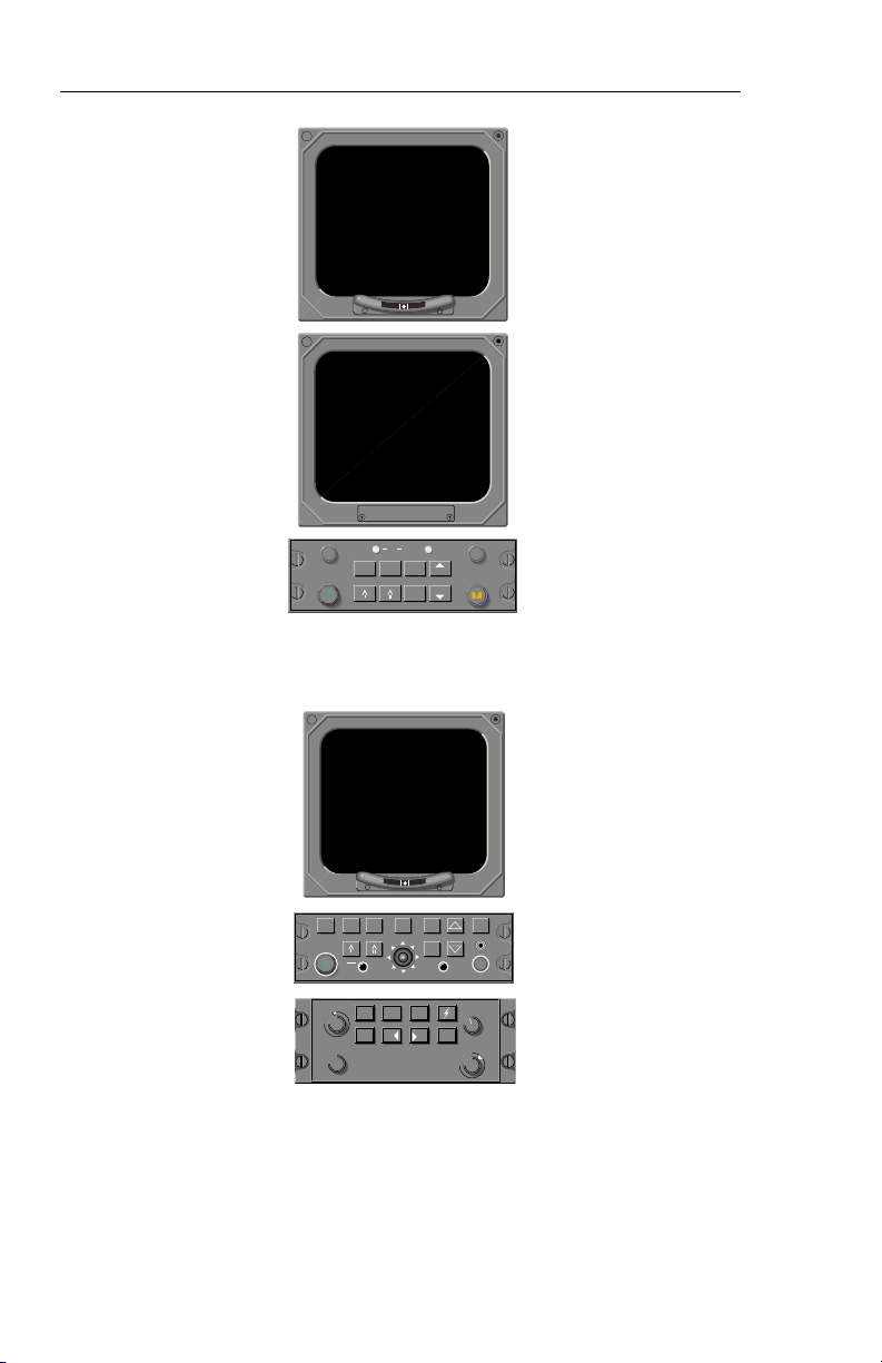
CONTROL DISPLAY
Refer to figure 1.1 for the Control
Display configurations.
The CP 467 Control Panel controls the presentation displayed
on the ED 551A Display Unit
when it is utilized as an EHSI or
EADI. The CP 469/A and CP
466A/B Control Panels control
the ED 551A Display Unit presentation when it is utilized as an
MFD (Multi Function Display).
Figure 1.1 depicts the EFS 50
Control Display Configurations.
Issued 4/95
SW 06/07/08/11
1.1
System Configuration
EADI, EHSI CONTROL DISPLAY
2 EA ED 551A & CP 467
ı
1
TST
RALT
SYS
REF
DH
HSI
ARC NAV
ı
BRT
RNG
HDGCRS
RNG
1-2
1.2
TCAS
ARC
HSI
ONLY
CRS
ON
TST
STBY
OFF
ENT
CRS
SEL
WxA
Wx
VP
TK
GAIN
CHK
NAV
LIST
1-2
TST
REF
BRT
GND
BRT
MAP
TK
OFF
UP
TILT O
DN
PULL AUTOPULL ARL
MFD CONTROL DISPLAY
ED 551/A, CP 469/A & CP 466B
Figure 1.1
CONTROL DISPLAY CONFIGURATIONS
SW 06/07/08/11
Issued 4/95
System Configuration
CONTROL DISPLAY OPTIONS
The CP 467 and CP 469/A mode
controllers offer a simple means
for the pilot to select the desired
display format, such as standard
compass rose or sectored compass rose, 360-degree map or
sectored map and weather radar
overlay. Also incorporated on
the mode controller is the course
and heading (CP 467) select
knobs with auto sync. The auto
sync feature will slew the head-
SG 465
ing bug to the lubber line or the
course pointer to the DIRECT TO
course for the selected NAV sensor providing a centered D-Bar.
The CP 467 incorporates Decision Height Set and Radio
Altimeter Test.
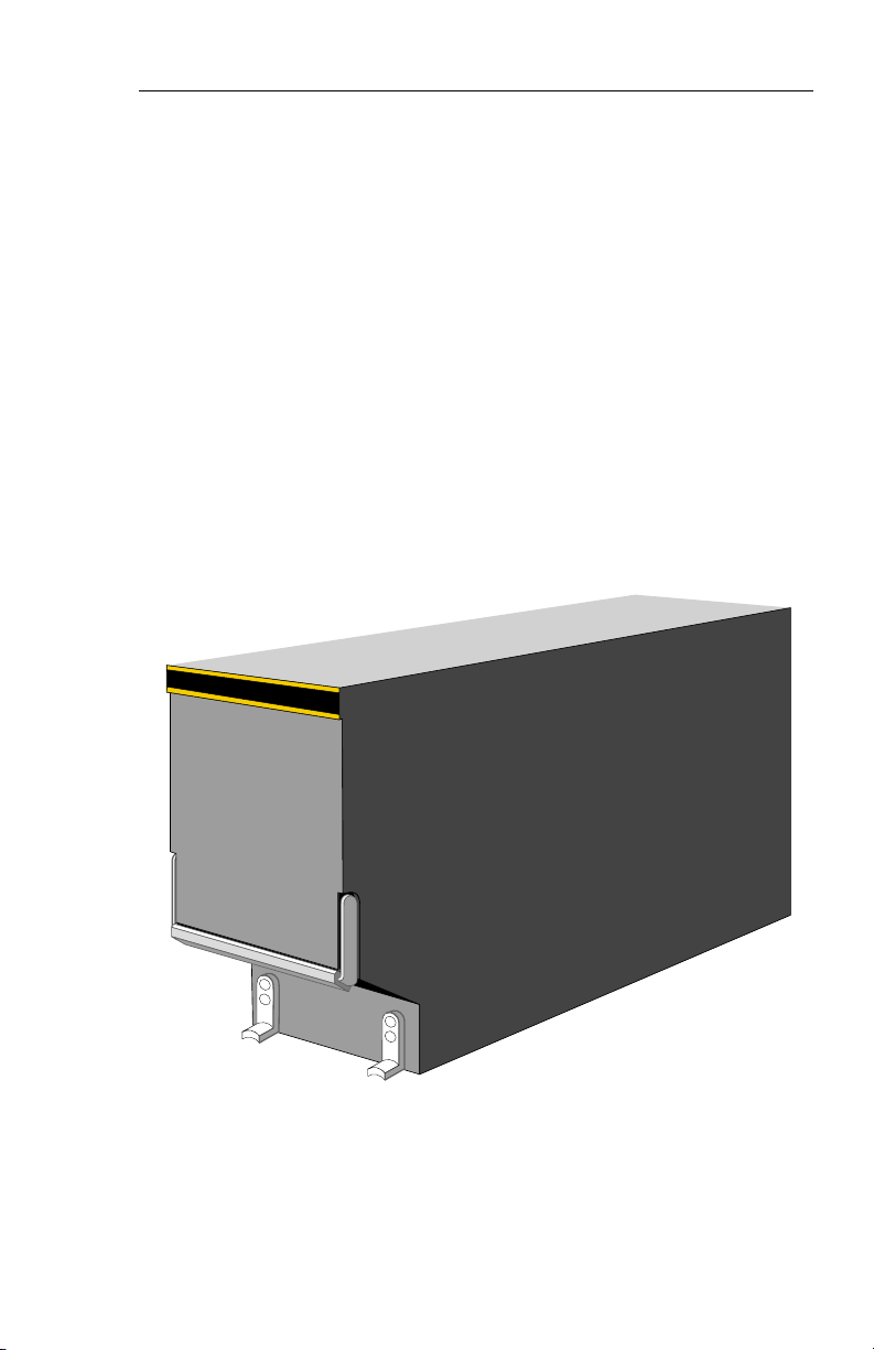
SYMBOL GENERATOR
THE SG 465 EADI/EHSI/MFD
symbol generator is a remotemounted processing unit packaged in an ARINC 3/8 ATR short
form factor.
Issued 4/95
Figure 1.2
SG 465 SYMBOL GENERATOR
SW 06/07/08/11
1.3
System Configuration
1
K
12555
LOC GSAP
1257
T
YD
201020
F
10
6
3NT
A
N
10
S
201020
LOC
257
ı
CRS
359
126
N
3
3
3
6
0
3
I
L
E
W
S
1
1
4
2
2
1
1
5
2
S
ADF 2
TST
RALT
SYS
DH
REF
HSI
ARC NAV
RNG
RNG
1-2
S
G
4
6
5
RA
G
S
DH
NM
3.5
G
S
360°
BRT
HDGCRS
ED 551A
ED 551A
CP 467
SG 465
1
340
CRS
23
3
3
V
O
R
1
ARL
WXA
A 2.2
ANT FLT
VOR 1
36.7 NM
ON
Wx
TST
STBY
OFF
GAIN
TCAS
HSI
ONLY
CRS
CRS
NM
36.7
243 KT
N
GND
WxA
MAP
PULL STAB OFF
ARC
ENT
NAV
1-2
TST
SEL
ED 551A
3
9
0
°
40
ADF 2
CP 466
UP
TILT 0
DN
CHK
LIST
CP 469A
REF
BRT
SG 465
S
G
4
6
5
1.4
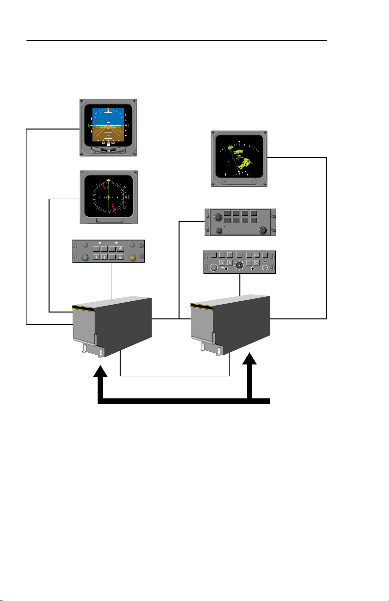
Figure 1.3
TYPICAL EFS 50 SYSTEM BLOCK DIAGRAM
SW 06/07/08/11
REMOTE
EQUIPMENT
{
Issued 4/95

EQUIPMENT INTERFACE & OPERATING CONFIGURATION
The following pages are provided
to document the EFS 50 equipment interface and operating
configuration established at the
time of installation and certification. Those pages referring to
software configuration versions
not applicable to this aircraft are
to be removed from this pilot’s
guide.
System Configuration
Issued 4/95
SW 06/07/08/11
1.5

System Configuration
SOFTWARE 06 CONFIGURATION PAGES
The EHSI, EADI, MFD and Reversion software will display the following pages. All display information will be identical on the EHSI and
MFD,, however, the EADI will not display the rack configurations, it will
display a comparison of the EHSI and EADI configuration data. The
descriptions given in this section refer to side 1 (left side) as the pilot’s
side and side 2 (right side) as the co-pilot’s side.
——————————|
1 VIEW/EDIT EQUIPMENT PG 01
2 ITEM
3 SG NUMBER _______________
4 SINGLE/DUAL _______________
5 DU TYPE _______________
6 ATTITUDE/HDG #1 _______________
7 ATTITUDE/HDG #2 _______________
8 RATE OF TURN _______________
9 ADF #1 _______________
10 ADF #2 _______________
11 VOR/ILS #1 _______________
12 VOR/ILS #2 _______________
13 ..MORE..
——————————|
1 VIEW/EDIT EQUIPMENT PG 02
2 ITEM
3 DME #1 _______________
4 DME #2 _______________
5 MLS #1 _______________
6 MLS #2 _______________
7 FMS #1 _______________
8 FMS #2 _______________
9 RNAV #1 _______________
10 RNAV #2 _______________
11 TACAN #1 _______________
12 TACAN #2 _______________
13 ..MORE..
1.6
SW 06/07/08/11
Issued 4/95

System Configuration
——————————|
1 VIEW/EDIT EQUIPMENT PG 03
2 ITEM
3 VNAV _______________
4 RADAR ALT _______________
5 AFCS TYPE _______________
6 AFCS COMMAND BAR _______________
7 AFCS MODE ANN _______________
8 F/S AIR DATA _______________
9 RADAR TYPE _______________
10 RADAR CTL PNL _______________
11 RADAR INDICATOR _______________
12 CHECKLIST _______________
13 ..MORE..
——————————|
1 VIEW/EDIT EQUIPMENT PG 04
2 ITEM
3 JOYSTICK _______________
4 TCAS _______________
5 HOMING #1 _______________
6 HOMING #2 _______________
7 LIGHTNING DET _______________
Issued 4/95
SW 06/07/08/11
1.7

System Configuration
——————————|
1 VIEW/EDIT OPERATING CHAR PG 06
2 ITEM
3 VERT SCALE SIDE _______________
4 DCLTR GS ON BC _______________
5 FULLTIME FMS MAP _______________
6 DISPLAY WIND VEC _______________
7 DISPLAY DRIFT _______________
8 DG ONLY MODE _______________
9 DME DIST ONLY _______________
10 RADAR ONLY MODE _______________
11 HOVER MODE _______________
12 MFD NAV CONTROL _______________
13 ..MORE..
——————————|
1 VIEW/EDIT OPERATING PG 07
2 ITEM
3 DISPLAY HDG TAPE _______________
4 COMMAND BARS _______________
5 ROLL INDICATOR _______________
6 DCLTR UNUS ATT _______________
7 CAT II AVAILABLE _______________
8 PERSPECTIVE LINES _______________
9 DH SELECT _______________
10 CABLE MODE _______________
11 SEL HDG SYNC _______________
12 SEL CRS SYNC _______________
13 ..MORE..
1.8
SW 06/07/08/11
Issued 4/95

System Configuration
——————————|
1 VIEW/EDIT OPERATING PG 08
2 ITEM
3 NORTH UP MAP _______________
4 VERT PTR TYPE _______________
5 DISPLAY FMS MSG _______________
6 SEL HDG COLOR _______________
7 CMD BAR COLOR _______________
8 REV MODE ANN _______________
9 RISING RUNWAY _______________
10 ADI DEV SRC _______________
11 CMD BAR FILTER _______________
Issued 4/95
SW 06/07/08/11
1.9

System Configuration
SOFTWARE 07 CONFIGURATION PAGES
(includes both 0701 and 0702)
The EHSI, EADI, MFD and Reversion software will display the following pages. All display information will be identical on the EHSI and
MFD, however, the EADI will not display the rack configurations, it will
display a comparison of the EHSI and EADI configuration data. The
descriptions given in this section refer to side 1 (left side) as the pilot’s
side and side 2 (right side) as the co-pilot’s side.
——————————|
1 VIEW/EDIT EQUIPMENT PG 01
2 ITEM
3 SG NUMBER _______________
4 SINGLE/DUAL _______________
5 DU TYPE _______________
6 ATTITUDE/HDG #1 _______________
7 ATTITUDE/HDG #2 _______________
8 RATE OF TURN _______________
9 ADF #1 _______________
10 ADF #2 _______________
11 VOR/ILS #1 _______________
12 VOR/ILS #2 _______________
13 ..MORE..
1.10
SW 06/07/08/11
Issued 4/95

System Configuration
——————————|
1 VIEW/EDIT EQUIPMENT PG 02
2 ITEM
3 DME #1 _______________
4 DME #2 _______________
5 MLS #1 _______________
6 MLS #2 _______________
7 FMS #1 _______________
8 FMS #2 _______________
9 RNAV #1 _______________
10 RNAV #2 _______________
11 TACAN #1 _______________
12 TACAN #2 _______________
13 ..MORE..
——————————|
1 VIEW/EDIT EQUIPMENT PG 03
2 ITEM
3 VNAV _______________
4 RADAR ALT _______________
5 AFCS TYPE _______________
6 AFCS COMMAND BAR _______________
7 AFCS MODE ANN _______________
8 F/S AIR DATA _______________
9 RADAR TYPE _______________
10 RADAR CTL PNL _______________
11 RADAR INDICATOR _______________
12 CHECKLIST _______________
13 ..MORE..
Issued 4/95
SW 06/07/08/11
1.11

System Configuration
——————————|
1 VIEW/EDIT EQUIPMENT PG 04
2 ITEM
3 JOYSTICK _______________
4 TCAS _______________
5 HOMING #1 _______________
6 HOMING #2 _______________
7 LIGHTNING DET _______________
8 HOVER MODE _______________
9 CABLE MODE _______________
——————————|
1 VIEW/EDIT OPERATING CHAR PG 06
2 ITEM
3 VERT SCALE SIDE _______________
4 DCLTR GS ON BC _______________
5 FULL TIME FMS MAP _______________
6 DISPLAY WIND VEC _______________
7 DISPLAY DRIFT _______________
8 DG ONLY MODE _______________
9 DME DIST ONLY _______________
10 RADAR ONLY MODE _______________
11 SPARE _______________
12 MFD NAV CONTROL _______________
13 ..MORE..
1.12
SW 06/07/08/11
Issued 4/95

System Configuration
——————————|
1 VIEW/EDIT OPERATING PG 07
2 ITEM
3 DISPLAY HDG TAPE _______________
4 COMMAND BARS _______________
5 ROLL INDICATOR _______________
6 DCLTR UNUS ATT _______________
7 CAT II AVAILABLE _______________
8 PERSPECTIVE LINES _______________
9 DH SELECT _______________
10 CTL PNL SYNC _______________
11 SEL HDG SYNC _______________
12 SEL CRS SYNC _______________
13 ..MORE..
1 VIEW/EDIT OPERATING PG 08
2 ITEM
3 NORTH UP MAP _______________
4 VERT PTR TYPE _______________
5 DISPLAY FMS MSG _______________
6 SEL HDG COLOR _______________
7 CMD BAR COLOR _______________
8 REV MODE ANN _______________
9 RISING RUNWAY _______________
10 ADI DEV SRC _______________
11 CMD BAR FILTER _______________
Issued 4/95
SW 06/07/08/11
1.13

System Configuration
SOFTWARE 08 CONFIGURATION PAGES
The EHSI, EADI, MFD and Reversion software will display the following pages. All display information will be identical on the EHSI and
MFD, however, the EADI will not display the rack configurations, it will
display a comparison of the EHSI and EADI configuration data. The
descriptions given in this section refer to side 1 (left side) as the pilot’s
side and side 2 (right side) as the co-pilot’s side.
——————————|
1 VIEW/EDIT EQUIPMENT PG 01
2 ITEM
3 SG NUMBER _______________
4 SINGLE/DUAL _______________
5 DU TYPE _______________
6 ATTITUDE/HDG #1 _______________
7 ATTITUDE/HDG #2 _______________
8 RATE OF TURN _______________
9 ADF #1 _______________
10 ADF #2 _______________
11 VOR/ILS #1 _______________
12 VOR/ILS #2 _______________
13 ..MORE..
——————————|
1 VIEW/EDIT EQUIPMENT PG 02
2 ITEM
3 DME #1 _______________
4 DME #2 _______________
5 MLS #1 _______________
6 MLS #2 _______________
7 FMS #1 _______________
8 FMS #2 _______________
9 RNAV #1 _______________
10 RNAV #2 _______________
11 TACAN #1 _______________
12 TACAN #2 _______________
13 ..MORE..
1.14
SW 06/07/08/11
Issued 4/95

System Configuration
——————————|
1 VIEW/EDIT EQUIPMENT PG 03
2 ITEM
3 VNAV _______________
4 RADAR ALT _______________
5 AFCS TYPE _______________
6 AFCS COMMAND BAR _______________
7 AFCS MODE ANN _______________
8 F/S AIR DATA _______________
9 RADAR TYPE _______________
10 RADAR CTL PNL _______________
11 RADAR INDICATOR _______________
12 CHECKLIST _______________
13 ..MORE..
——————————|
1 VIEW/EDIT EQUIPMENT PG 04
2 ITEM
3 JOYSTICK _______________
4 TCAS _______________
5 HOMING #1 _______________
6 HOMING #2 _______________
7 LIGHTNING DET _______________
8 HOVER MODE _______________
9 CABLE MODE _______________
Issued 4/95
SW 06/07/08/11
1.15

System Configuration
——————————|
1 VIEW/EDIT OPERATING CHAR PG 06
2 ITEM
3 VERT SCALE SIDE _______________
4 DCLTR GS ON BC _______________
5 FULL TIME FMS MAP _______________
6 DISPLAY WIND VEC _______________
7 DISPLAY DRIFT _______________
8 DG ONLY MODE _______________
9 DME DIST ONLY _______________
10 RADAR ONLY MODE _______________
11 SPARE _______________
12 MFD NAV CONTROL _______________
13 ..MORE..
——————————|
1 VIEW/EDIT OPERATING PG 07
2 ITEM
3 DISPLAY HDG TAPE _______________
4 COMMAND BARS _______________
5 ROLL INDICATOR _______________
6 DCLTR UNUS ATT _______________
7 CAT II AVAILABLE _______________
8 PERSPECTIVE LINES _______________
9 DH SELECT _______________
10 CTL PNL SYNC _______________
11 SEL HDG SYNC _______________
12 SEL CRS SYNC _______________
13 ..MORE..
1.16
SW 06/07/08/11
Issued 4/95

System Configuration
——————————|
1 VIEW/EDIT OPERATING PG 08
2 ITEM
3 NORTH UP MAP _______________
4 VERT PTR TYPE _______________
5 DISPLAY FMS MSG _______________
6 SEL HDG COLOR _______________
7 CMD BAR COLOR _______________
8 REV MODE ANN _______________
9 RISING RUNWAY _______________
10 ADI DEV SRC _______________
11 CMD BAR FILTER _______________
12 MLS VRT ANNUNC _______________
13 ..MORE..
——————————|
1 VIEW/EDIT OPERATING PG 09
2 ITEM
3 DATUM SCALING _______________
4 HDG FAIL ANNUNC _______________
5 VNAV APR SCALE _______________
6 LNAV CRS CTRL _______________
7 SG #1 SIDE _______________
8 AIRCRAFT SYMBOL _______________
9 TACAN ANNUNC _______________
10 TCAS DISPLAYS _______________
11 CAT II SENSORS _______________
Issued 4/95
SW 06/07/08/11
1.17
Loading...