


 Loading...
Pilot’s Guide Gold Crown
|
|
|
|
Gold Crown |
||||
|
|
|
|
|
Avionics |
|||
|
|
|
|
|
ı |
|
|
|
|
|
|
|
R 2200 |
|
|
||
|
|
|
|
TA/RA 5 |
<> |
|
I |
|
|
|
|
|
|
D |
|||
|
|
|
|
|
|
|
|
T |
|
|
|
|
|
IDT |
|
|
|
|
|
|
|
|
XPDR/TCAS |
|
|
|
|
|
|
|
RANGE |
ALT |
|
VFR |
|
|
|
|
|
|
ON |
|
|
TA |
|
|
|
|
OFF |
SBY |
|
FL |
TA/ |
|
|
|
|
|
TST |
|
|
RA |
|
|
|
|
PUSH |
^ |
|
|
|
|
|
|
|
|
^ 1/2 |
|
|
|
92.4NM1180 KT31 MIN |
|
|
|
|
|
|
|
|
|
HLD |
|
|
|
|
|
|
|
N 1 |
N 2 |
|
|
|
|
|
|
|
ı OFF |
|
|
|
|
|
|
|
|
|
|
1482 NM |
|
356 KT |
|
|
|
|
|
|
NAV |
N |
3 |
COMPASS |
|
|
|
|
|
33 |
|
6 |
|
|
|
|
|
|
30 |
|
|
|
|
||
|
G |
|
|
|
|
|
|
|
|
S |
|
|
E |
|
|
|
|
|
O |
W |
|
|
|
|
|
|
|
F |
|
|
|
|
|
|
|
|
F |
|
|
12 |
|
|
|
|
|
|
24 |
|
|
|
|
|
|
|
|
|
15 |
|
|
|
|
|
|
|
21 |
|
|
|
|
|
|
|
|
|
S |
NAV |
|
|
|
|
|
COURSE |
|
HDG |
|
|
|||
|
|
|
|
|
||||

Table of Contents
This Pilot’s Guide compiles the operation sections from Bendix/King Gold Crown Installation manuals.
The major sections of this Pilot’s Guide are arranged by unit type with the subsections being individual units.
VHF COMM |
|
KFS 598 |
2 |
KFS 598A |
3-5 |
NAV/VOR/ILS |
|
KFS 564 |
6 |
KFS 564A |
7-9 |
Navigation Indicator |
10 |
Radio Magnetic Indicator (RMI) |
11 |
KPI 552B and KPI 553A/B Controls and Indicators |
12-13 |
DME/TACAN |
|
KDI 572/573/574 When Used With the KDM 706/706A |
14-16 |
KFS 579A AND KDI 572/573/574 When Used With the KTU 709 |
16-18 |
KFS 579A TACAN Control Unit |
19 |
KFS 579A NAV/TACAN Control Unit |
20-21 |
TACAN/DME Channel Designation and Paired Frequencies Table 22-24 |
|
ATCRBS TRANSPONDER |
|
KFS 576/KFS 576A |
25-27 |
RMI |
|
KNI 582 |
28 |
ADF |
|
KFS 586/586A |
29-33 |
HF/SSB COMM |
|
KFS 594 |
34-35 |
KCU 951 |
36-39 |
MARKER BEACON |
|
KA 35 When Used With the KMR 675 |
40-41 |
RADAR ALTIMETER |
|
KNI 415/416 |
42-44 |
MODE S TRANSPONDER |
|
KFS 578A |
45-48 |
1

VHF Comm
KFS 598 Operating
Procedures
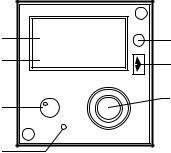
Rotate the VOL control knob clockwise from the OFF position. To override the automatic squelch pull the VOL knob out and rotate the VOL control for desired listening level on the noise being produced by the receiver. Push the VOL knob back in to activate the automatic squelch.
Select the desired operating frequency in the Standby display by rotating the Frequency Control knobs either clockwise or counterclockwise. A clockwise rotation will increase the frequency while a counterclockwise rotation will decrease the frequency. The larger tuning knob will increase or decrease the MHz portion of the display in 1 MHz steps. At band edge
(118 MHz on the low end and either
136 or 151 MHz on the high end) the next 1 MHz step will cause the display to wrap around to the opposite band edge. The smaller tuning knob will increase or decrease the KHz portion of the display in 50 KHz steps with the knob pushed in or in 25 KHz steps with the knob pulled out. Rollover to the opposite band edge occurs at 000 and 975 KHz. While in the Standby Entry mode, the transceiver remains tuned to the frequency displayed in the Active window at all times. To transfer the Standby Frequency to the active, press the Transfer Button. During the transmit operation, a TX annunciation will light just right of the active display, signifying that the transceiver is in the Transmit mode of operation.
ACTIVE WINDOW
STANDBY WINDOW
ON/OFF/VOL SQUELCH TEST
|
ı |
|
TX ANNUNCIATOR |
|
|
|
|
118.00) |
PHOTOCELL |
||
13697 |
S |
|
|
B |
TRANSFER BUTTON |
||
|
|
Y |
|
|
COMM |
|
|
|
VOL |
|
|
OFF |
PULL |
PULL |
FREQUENCY |
|
|||
|
TEST |
||
|
25K |
CONTROL KNOBS |
|
|
|
|
|
KFS 598 Comm Control Functions
2
ACTIVE WINDOW
STANDBY WINDOW
ON/OFF/VOL
CHAN BUTTON
|
ı |
|
118.00S |
PHOTOCELL |
|
136.97YB |
TRANSFER BUTTON |
|
|
|
|
|
COMM |
|
|
VOL |
FREQUENCY |
OFF |
PULL |
|
|
CONTROL KNOBS |
|
|
TEST |
|
|
CHAN |
|
KFS 598A Control Functions |
|
|
KFS 598A Operating
Procedures
Rotate the VOL control knob clockwise from the OFF position. A momentary unsquelched state will occur. To override the automatic squelch state, push the PUSH TST knob. To return to the squelched state push the PUSH TST knob once again.
When the mic is keyed, the TX annunciator will light just right of the active display. If the mike key is held down for more than 1-1/2 minutes, the key line to the KTR 908 will be disabled. The total display will then flash as long as the mic key is depressed.
Frequency Mode:
Standby Entry
Frequency selection is accomplished in the Standby Entry mode by changing the frequency displayed in the Standby window of the display with
the tuning knobs, and then transferring the selected frequency into the Active window by pressing the Transfer button. The larger tuning knob will increase or decrease the MHz portion of the display in 1 MHz steps. At band edge (118 MHz on the low end and either 136 or 151 MHz on the high end) the next 1 MHz step will cause the display to wrap around to the opposite band edge. The smaller tuning knob will increase or decrease the KHz portion of the display in 50 KHz steps with the knob pushed in or in 25 KHz steps with the knob pulled out. Rollover to the opposite band edge occurs at 000 and 975 KHz. While in the Standby Entry mode, the transceiver remains tuned to the frequency displayed in the Active window at all times. During the transmit operation, a TX annunciation will light just right of the active display, signifying that the transceiver is in the Transmit mode of operation.
3
Civil Operation
Active Entry
The Active Entry mode is entered by pressing and holding the Transfer button for more than 2 seconds. The frequency displayed in the Active window may then be changed with the Frequency Control knobs in the same manner as described above. The receiver will be tuned to the frequency displayed in the Active window at all times.
Momentarily pressing the Transfer button will return the control unit to the Standby Entry mode. The Standby frequency displayed prior to entering the Active Entry mode remains unchanged.
Channel Mode
A. Momentarily pressing the CHAN button while in Frequency mode puts the unit in Channel mode. The unit remains tuned to the last active frequency displayed before entering Channel mode. The last used channel number is displayed unless no channels have been programmed, in which case the unit defaults to Channel 1 and dashes are displayed in the Standby window.
Turning either tuning knob changes the channel number and corresponding frequency. The channels will only increase and decrease to channels that have been programmed. If there has been no activity for five seconds the unit will return to Frequency mode and the channel frequency is placed in the Standby window. Pressing the CHAN button before the 5 second delay is completed will return the unit to Frequency mode and the status of Frequency mode prior to entering Channel mode remains the same.
B. When in Channel mode, pressing the Transfer button will return the unit to Frequency mode. The channel frequency will become the new Active frequency and the last Active frequency will become the new Standby frequency. If the unit was in Active Entry mode prior to entering Channel mode, pressing the Transfer button or allowing the unit to time out will bring it back to Standby Entry.
Program Mode
A.Program mode is selected by pressing and holding the CHAN button for longer than two seconds. The unit tunes the KTR 908 to last active frequency displayed before entering Program mode and the last used Channel number is displayed when Program mode is entered. The Channel number flashes and turning either tuning knob changes the Channel number. When the Channel number is flashing, pressing the Transfer button will cause the Channel number to stop flashing and cause the frequency to flash, unless the channel is Program Secured. The secured mode prevents the pilot from changing the programmed channels. This is accomplished by a strap in the aircraft wiring.
The tuning knobs then work as in Frequency mode, except between rollover points 118.XX to 136.XX and 136.XX to 118.XX, or 118.XX to 151.XX and 151.XX to 118.XX for extended frequency range, dashes are displayed to unprogram the channel. When frequency is flashing, pressing the Transfer button will cause the frequency to stop flashing and the Channel number to flash allowing the next channel to be programmed.
B.If no activity has occurred for 20 seconds the unit returns to Frequency mode. The unit can also
4
be returned to Frequency mode from Program mode by pressing the CHAN button. Returning to Frequency mode will not change the Active or Standby frequencies from what they were prior to entering Program mode.
Remote Transfer
Operates identically as front panel Transfer button with the exception that holding the Remote Transfer button for two seconds does not place unit in Active Entry.
Military Operation
Channel Mode
The Channel Mode operates the same as in civil operation except the Channel Mode does not time out and return to the Frequency Mode.
Program Mode
The Program Mode operates the same as in civil operation.
Default Mode
Turning the units on while holding the Transfer button down will bring the unit on in Active Entry and load 120.00MHz as the Active frequency. This will aid the pilot in blind tuning the radio in the case of display failure.
Remote Transfer
Operates identically as front panel Transfer button with the exception that holding the Remote Transfer button for two seconds does not place unit in Active Entry.
Remote Channel
Pressing the Remote Channel button will cause the system to enter the Channel mode of operation and will increase the channel from the previous channel number used.
5
NAV/VOR/ILS
KFS 564
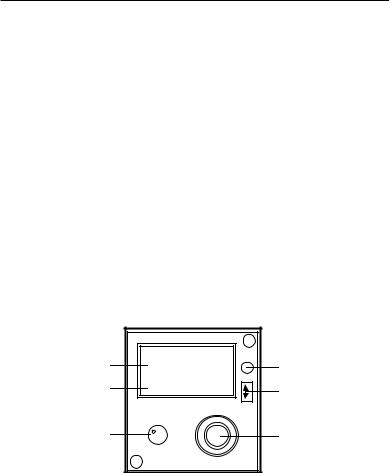
Rotate the VOL control clockwise from the OFF position to turn the system on. Clockwise rotation beyond the OFF position will increase the NAV audio volume. Counterclockwise rotation will decrease the audio volume.
Frequency selection is accomplished with the Frequency Control knobs. Clockwise rotation will increase the frequency and counterclockwise rotation will decrease the frequency. The larger knob will change the MHz portion of the display. At band edge (108 or 117MHz) the next 1MHz step will cause the display to wrap around to the opposite band edge. The smaller
knob will change the KHz portion of the display and will wrap around at the band edges (00 and 95) in the same manner.
With the smaller Frequency Control knob pushed in, frequency selection is accomplished by entering a frequency into the Standby display and then transferring that frequency into the Active window by pressing the Transfer button. Frequency selection may be accomplished directly in the Active window by pulling the smaller Frequency Control knob out, waiting until the Standby display shows dashes (— — —), and then entering
the desired frequency. The receiver will remain tuned to the frequency displayed in the Active window at all times.
ACTIVE WINDOW
STANDBY WINDOW
ON/OFF/VOL
ı |
|
108.00S |
PHOTOCELL |
117.95YB |
TRANSFER BUTTON |
|
|
NAV |
|
VOL |
|
OFF |
|
|
FREQUENCY |
|
CONTROL KNOBS |
KFS 564 Control Functions
6

ACTIVE WINDOW
STANDBY WINDOW
ON/OFF/VOL
CHAN BUTTON
ı |
|
108.00S |
PHOTOCELL |
117.95YB |
TRANSFER BUTTON |
|
|
NAV |
|
VOL |
FREQUENCY |
OFF |
|
|
CONTROL KNOBS |
CHAN |
|
KFS 564A Control Functions |
|
KFS 564A
On/Off and VOL Control
Rotate the VOL control clockwise from the OFF position to turn the system on. Clockwise rotation beyond the OFF position will increase the NAV audio volume. Counterclockwise rotation will decrease the audio volume.
Frequency Mode:
Standby Entry
Frequency selection is accomplished in the Standby Entry mode by changing the frequency displayed in the Standby window of the display with the Frequency Select knobs, and then transferring the selected frequency into the Active window by pressing the Transfer button. The larger control knob will increase or decrease the MHz portion of the display in 1MHz steps with rollover at each band edge (108 or 117MHz). The smaller
Frequency Control knob will increment or decrement the KHz portion of the display in 50KHz steps. Rollover to the opposite band edge occurs at 00 or 95. While in the Standby Entry mode, the receiver remains tuned to the frequency displayed in the Active window at all times.
Active Entry
The Active Entry mode is entered by pressing and holding the Transfer button for more than 2 seconds. The frequency displayed in the Active window may then be changed with the Frequency Control knobs in the same manner as described above. The receiver will be tuned to the frequency displayed in the Active window at all times.
Momentarily pressing the Transfer button will return the control unit to the Standby Entry mode. The Standby frequency displayed prior to entering the Active Entry mode remains unchanged.
7
Civil Operation
Channel Mode
Momentarily pressing the CHAN button while in the Frequency mode will place the unit in the Channel mode. The receiver will remain tuned to the last Active frequency displayed before entering the Channel mode. The last Channel number used will be displayed, unless no channels have been programmed, in which case the unit defaults to Channel 1 and dashes are displayed in the Standby window.
Turning either Frequency Control knob will increase or decrease the Channel number. The unit will only increase or decrease to channels that have been programmed. The frequency associated with each Channel number will be displayed in the Standby window. If there is no knob activity for 5 seconds the unit will return to the Frequency mode and the Channel frequency will be displayed in the Standby window. Pressing the CHAN button will return the unit to the Frequency mode and the status of the Frequency mode prior to entering the Channel mode will remain the same.
When in the Channel mode, pressing the Transfer button will return the unit to the Frequency mode. The Channel frequency will become the new Active frequency and the last frequency used will be the new Standby frequency. If the unit was in the Active Entry mode prior to entering the Channel mode, pressing the Transfer button or allowing the unit to time out will bring the unit back to the Standby Entry mode.
Program Mode
The Program mode is entered by pressing and holding the CHAN button for more than 2 seconds. The receiver remains tuned to the last Active frequency displayed before entering the Program mode and the last Channel number used will be displayed. The Channel number will be flashing and may be changed with the Frequency Control knobs. Pressing the Transfer button will cause the Channel number to stop flashing and cause the frequency to flash (unless the channel is Program Secured). The frequency may then be changed with the Frequency Control knobs in the same manner as described above with the exception that the first step past any band edge will cause dashes to be displayed. Any Channel with dashes displayed will be unprogrammed. Pressing the Transfer button will cause the frequency displayed to stop flashing and the Channel number will flash allowing the next channel to be programmed.
The unit will revert to the Frequency mode if no knob activity takes place for 20 seconds. The unit may also be returned to the Frequency mode from the Program mode by momentarily pressing the CHAN button. On reentering the Frequency mode the Active and Standby frequencies displayed will be the last frequencies displayed prior to entering the Program mode.
Remote Transfer
Operates identically to the front panel Transfer button with the exception that holding the Remote Transfer button for 2 seconds does not cause the unit to enter the Active Entry mode.
8
Military Operation
Channel Mode
Momentarily pressing the CHAN button while in the Frequency mode places the unit in the Channel mode. The last channel used will be the Channel number displayed. The receiver will be tuned to the frequency displayed in the Standby window. If no channels are programmed into the unit, the unit will display “CH 1” and dashes in the Standby display for 5 seconds and will tune the receiver to the last Active frequency. The unit will only channel to channel numbers with a frequency programmed into them.
Note: Channel mode does not time out as in civil operation.
Momentarily pressing the CHAN button will return the unit to the Frequency mode and the status will remain as it was prior to entering the Channel mode. Holding the Transfer button depressed for more than 2 seconds while in the Channel mode will cause the unit to enter the Active Tune mode.
Program Mode
Pressing and holding the CHAN button for longer than 2 seconds will cause the unit to enter the Program mode. The last channel in use will be displayed and will be flashing. The receiver will be tuned to the last Active frequency. While flashing, the Channel number may be changed with the Frequency Control knobs. Pressing the Transfer button will cause the Channel number to stop flashing and the frequency in the Standby window will flash. The frequency may then be changed with
the Frequency Control knobs in the manner described above. The first step past either band edge will cause dashes to be displayed in the Standby window. Any Channel with dashes entered will be unprogrammed. An unprogrammed Channel will display dashes in the Standby window when recalled, in which case the receiver will be tuned to the last valid Active frequency.
Pressing the CHAN button will return the unit to the mode in use prior to entering the Program mode. The receiver will be tuned to the frequency displayed in the Active window if it returns to the Frequency mode or will be tuned to the frequency displayed in the Standby window if it returns to the Channel mode.
Default Mode
Turning the unit on while holding the Transfer button down will bring the unit on in the Active Entry mode and display 110.00 as the Active frequency. This will aid the pilot in blind tuning the unit in case of a display failure.
Remote Transfer
Operates identically to the front panel Transfer button with the exception that holding the Remote Transfer button for 2 seconds does not cause the unit to enter the Active Entry mode.
Remote Channel
Pressing the Remote Channel button will cause the system to enter the Channel mode of operation and will increment the channel from the previous channel number used.
9
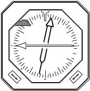
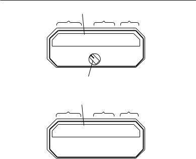
Navigation Indicator
Omni-bearing Selector (OBS)
The omni-bearing selector is used to select the desired course. The VOR radial selected serves as a reference for all VOR indications.
VOR/LOC Deviation Indicator
The VOR/LOC deviation needle indicates the direction and amount of deviation from the selected VOR radial or localizer path.
Glideslope Deviation Indicator
The Glideslope deviation needle indicates the direction and amount of deviation from the glidepath.
TO/FROM Indicator
The TO/FROM flag indicates whether the direction to the VOR station is within the semicircle centered about the direction selected on the omni-bearing selector or within
the semicircle centered about the reciprocal of the selected course. If the station direction is within 90 degrees of the selected course radial, the FROM flag will be visible.
VOR/LOC Warning Flag
The VOR/LOC warning flag is fully visible when the VOR or LOC signals are unreliable or when a malfunction has occurred in the NAV receiver. The flag is out of view when the signal is reliable and the system is operating properly.
Glideslope Warning Flag
The Glideslope warning flag is fully visible when the glideslope signal is unreliable or when a malfunction has occurred in the glideslope receiver. The flag is out of view when the signal is reliable and the glideslope receiver is functioning properly.
VOR / LOC |
VOR / LOC WARNING |
NEEDLE |
FLAG |
|
|
33 |
N |
3 |
|
|
|
|
|
||
|
30 |
|
|
|
|
|
|
V |
|
6 |
|
GLIDESLOPE |
|
|
N |
TO |
|
|
|
A |
|
||
WARNING FLAG |
|
GS |
|
|
|
|
|
|
|
|
|
|
W |
|
|
|
E |
|
24 |
|
|
FR |
12 |
GLIDESLOPE NEEDLE |
|
|
|
||
|
|
|
|
||
|
|
|
|
|
|
OBS KNOB |
OBS |
12 |
S |
15 |
|
|
|
|
|
|
TO-FROM FLAG
AZIMUTH CARD
Navigation Indicator
10
Radio Magnetic Indicator (RMI)
The VOR needle on the RMI continuously indicates the magnetic heading to the station referenced to the RMI compass card.
HDG N
33
|
30 |
A |
W |
|
|
D |
|
F |
24 |
21 |
S |
|
|
VOR |
|
3
6
E
12
15
VOR
A  D
D  F
F
Radio Magnetic Indicator (RMI)
11
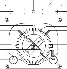
KPI 552B and KPI 553A/B
Indicator
The following controls and indicators are on the KPI 552B and KPI 553A/B.
N KPI 553A/B
O |
P&Q |
A |
|
|
|
|
|
G |
L |
|
|
N |
3 |
|
K |
M |
|
|
|
|
||
|
33 |
|
|
|
||
|
|
|
|
|
||
C |
S |
|
|
6 |
|
|
|
G |
30 |
|
|
|
|
|
|
|
|
|
||
I |
O |
|
E |
|
B |
|
F |
W |
|
|
|||
D |
F |
|
|
|
J |
|
|
|
12 |
|
|||
|
|
|
A |
|||
|
|
|
|
|
||
|
|
24 |
|
|
D |
|
|
|
21 |
|
15 |
F |
|
H |
|
S |
|
E |
||
COURSE |
|
HDG |
||||
|
|
|
|
F |
||
|
|
|
|
|
|
12
A.Lubber Line
Fixed reference mark for compass card. Represents nose of aircraft.
B.Heading Bug (Orange)
Indicates Selected Heading.
C.TO-FROM Indicator
Indicates whether the course pointer is showing the magnetic bearing TO or FROM the station.
D.Lateral Deviation Indicator
Indicates flight on selected VOR radial, localizer beam or RNAV track with respect to aircraft location. Scale is 1 dot equals typically ±.5° of localizer deviation, ±2° of VOR deviation, ±1 mile or RNAV Enroute deviation, and ±.25 mile RNAV Approach deviation.
E.Heading Select Knob
Positions Heading Bug on Compass Card. Knob face includes a color coded symbol representing the Heading Bug.
F.ADF/NAV Selector
Rotating lever determines which information the ADF/NAV indicator
(G)is displaying. Automatic direction finder (ADF) and radio magnetic indicator (RMI or NAV) information is supplied by aircraft avionics.
G.ADF/NAV Indicator (Green)
Indicates bearing of ADF or NAV signal.
H.Course Select Knob
Positions course selector on compass card. Knob face includes a color coded symbol representing the Course Arrow.
I.Glideslope Deviation Indicator
Indicates glideslope beam center with respect to (from View) location. Glideslope scale is typically ±.35° per dot. A black glideslope warning flag covers this area when the glideslope signal is invalid.
J. Compass Card
Indicates aircraft magnetic heading with reference to Lubber Line.
K.Compass Warning Flag (Red)
In view when an erroneous directional gyro input, a power failure or a compass card servo failure occurs.
L.NAV Warning Flag (Red)
In view when navigational receiver output is invalid.
M.Course Arrow (Yellow)
Indicates Selected Course.
N.Photoresistor (KPI 553A/B)
Senses light for display dimming circuit.
O.Distance Display (KPI 553A/B)
The left-hand portion of the display shows distance (NM) to the VOR or waypoint, as determined by the function switch.
P.Groundspeed, Time-To-Go or Altitude (KPI 553A/B)
The right-hand portion of the display shows Groundspeed, Time- To-Go or Altitude as indicated by the illumination of the KT, H:M or FT legends.
Q.GS/TTG Transfer Button (KPI 553“B” only)
Pressing the GS/TTG transfer button switches the right-hand display from the GS display to the TTG display, or from TTG to GS depending on what is currently in use. This information is only displayed above 1250 ft. Below 1250 ft. the display changes to altitude as indicated by the legend.
13
DME/TACAN
CHANNELING SOURCE
RANGE GROUND SPEED TIME TO STATION
92.4 |
1 |
180 |
31 |
MIN |
|
NM |
|
KT |
|
||
|
|
HLD |
|
|
|
ı |
N 1 N 2 |
|
|
|
|
|
|
|
|
|
|
OFF |
|
|
|
||
FUNCTION SWITCH |
|
|
|
||
KDI 572 Display |
|
|
|||
CHANNELING SOURCE |
|
|
|
||
RANGE |
GROUND SPEED |
TIME TO STATION |
|||
92.41 |
180 |
31 |
MIN |
||
NM |
KT |
|
|||
ı
KDI 573/574 Display
DME
KDI 572/573/574 When Used With the KDM 706/706A
The effective range of a DME depends on many factors: most important being line of sight limitations determined by the altitude of the aircraft (see Table 1), weather, the location and altitude of the ground transmitter and transmitter power output. The degree of maintenance of the KDM 706/706A DME and maintenance of the ground station also contribute to a DME's effective range capability. Usually line-of-sight limitations will prevent an aircraft on the ground from receiving and locking onto a VORTAC station.
The DME system electronically
converts elapsed time-to-distance by measuring the length of time between the transmission of a radio signal to a pre-selected VORTAC station and reception of the reply signal. This distance is then indicated in nautical miles on the DME range/ground speed/time-to-station indicator. This distance is measured on a slant from the aircraft to the ground and is commonly referred to as slant-range distance. Slant-range distance should not be confused with actual ground distance. The difference between slant-range distance and ground distance is smallest at low altitude and long range. These distances may differ considerably when in close proximity to a VORTAC facility. However, if the range is three times
14
Loading...