


 Loading...
KHF 950/990
HF Communications Transceiver
PILOT’S GUIDE AND DIRECTORY OF HF SERVICES
A

Table of Contents
INTRODUCTION |
|
|
KHF 950/990 COMMUNICATIONS TRANSCEIVER . . |
. . . .I |
|
SECTION I |
|
|
CHARACTERISTICS OF HF SSB WITH ALE . . |
. . . . . |
.1-1 |
ACRONYMS AND DEFINITIONS . . . . . . . . . |
. . . . . |
.1-1 |
REFERENCES . . . . . . . . . . . . . . . . . . . . . . . |
. . . . . |
.1-1 |
HF SSB COMMUNICATIONS . . . . . . . . . . . . |
. . . . . |
.1-1 |
FREQUENCY . . . . . . . . . . . . . . . . . . . . . . . . |
. . . . . |
.1-2 |
SKYWAVE PROPAGATION . . . . . . . . . . . . . . |
. . . . . |
.1-3 |
WHY SINGLE SIDEBAND IS IMPORTANT . |
. . . . . |
.1-9 |
AMPLITUDE MODULATION (AM) . . . . . . . . . |
. . . . . |
.1-9 |
SINGLE SIDEBAND OPERATION . . . . . . . . |
. . . . . |
1-10 |
SINGLE SIDEBAND (SSB) . . . . . . . . . . . . . . |
. . . . . |
1-10 |
SUPPRESSED CARRIER VS. |
|
|
REDUCED CARRIER . . . . . . . . . . . . . . . . . . |
. . . . . |
1-10 |
SIMPLEX & SEMI-DUPLEX OPERATION . . . |
. . . . . |
1-11 |
AUTOMATIC LINK ESTABLISHMENT (ALE) |
. . . . .1-11 |
|
FUNCTIONS OF HF RADIO AUTOMATION . |
. . . . . |
1-11 |
ALE ASSURES BEST COMM |
|
|
LINK AUTOMATICALLY . . . . . . . . . . . . . . . . . |
. . . . . |
1-12 |
SECTION II |
|
|
KHF 950/990 SYSTEM DESCRIPTION. . . . . . . . . . . . . .2-1 |
||
KCU 1051 CONTROL DISPLAY UNIT . . . . . . |
. . . . . |
.2-1 |
KFS 594 CONTROL DISPLAY UNIT . . . . . . . |
. . . . . |
.2-3 |
KCU 951 CONTROL DISPLAY UNIT . . . . . . |
. . . . . |
.2-5 |
KHF 950 REMOTE UNITS . . . . . . . . . . . . . . . |
. . . . . |
.2-6 |
KAC 952 POWER AMPLIFIER/ANT COUPLER .2-6 |
||
KTR 953 RECEIVER/EXITER . . . . . . . . . |
. . . . . |
.2-7 |
ADDITIONAL KHF 950 INSTALLATION OPTIONS |
.2-8 |
|
SINGLE KHF 950 SYSTEM CONFIGURATION |
.2-9 |
|
KHF 990 REMOTE UNITS . . . . . . . . . . . . . . . |
. . . . . |
2-10 |
KAC 992 PROBE/ANTENNA COUPLER |
. . . . .2-10 |
|
KTR 993 RECEIVER/EXITER . . . . . . . . . |
. . . . . |
2-11 |
SINGLE KHF 990 SYSTEM CONFIGURATION . . .2-12
Rev. 0 |
KHF 950/990 Pilots Guide |
Toc-1 |
Dec/96 |

Table of Contents
SECTION III |
|
|
OPERATING THE KHF 950/990 . . . . . . . . . . . . . . . . . . |
. . . .3-1 |
|
KHF 950/990 GENERAL OPERATING INFORMATION |
. . . .3-1 |
|
PREFLIGHT INSPECTION . . . . . . . . . . . . . . . . . . . |
. . . .3-1 |
|
ANTENNA TUNING . . . . . . . . . . . . . . . . . . . . . . . . . |
. . . .3-2 |
|
FAULT INDICATION . . . . . . . . . . . . . . . . . . . . . . . . |
. . . .3-2 |
|
TUNING FAULTS . . . . . . . . . . . . . . . . . . . . . . . . . . . |
. . . .3-3 |
|
KHF 950/990 CONTROLS-GENERAL . . . . . . . . . . . |
. . . .3-3 |
|
KCU 1051 CONTROL DISPLAY UNIT OPERATION . . . |
. . . .3-4 |
|
KCU 1051 GENERAL OPERATING INFORMATION |
. . .3-4 |
|
|
KCU 1051 CONTROL DESCRIPTION . . . . . . . |
. . . .3-4 |
|
PUSH ON/VOL . . . . . . . . . . . . . . . . . . . . . . |
. . . .3-4 |
|
SQUELCH . . . . . . . . . . . . . . . . . . . . . . . . . |
. . . .3-4 |
|
CURSOR . . . . . . . . . . . . . . . . . . . . . . . . . . . |
. . . .3-5 |
|
VAR/PUSH CHAR . . . . . . . . . . . . . . . . . . . . |
. . . .3-5 |
|
CLEAR . . . . . . . . . . . . . . . . . . . . . . . . . . . . . |
. . . .3-6 |
|
ENTER . . . . . . . . . . . . . . . . . . . . . . . . . . . . |
. . . .3-6 |
|
MESSAGE . . . . . . . . . . . . . . . . . . . . . . . . . . |
. . . .3-7 |
|
SCAN . . . . . . . . . . . . . . . . . . . . . . . . . . . . . . |
. . . .3-7 |
|
KCU 1051 DISPLAY AND CONTROL OPERATION 3-8 |
|
|
DISPLAY . . . . . . . . . . . . . . . . . . . . . . . . . . . |
. . . .3-8 |
|
PAGES . . . . . . . . . . . . . . . . . . . . . . . . . . . . . |
. . . .3-8 |
|
DATA STORE AND RECALL KEYS . . . . . . |
. . .3-10 |
|
CLR KEY . . . . . . . . . . . . . . . . . . . . . . . . |
. . .3-10 |
|
ENT KEY . . . . . . . . . . . . . . . . . . . . . . . . |
. . .3-10 |
|
MICROPHONE KEY OPERATION. . . . . . . . . .3-11 |
|
|
OPERATOR ALERTS . . . . . . . . . . . . . . . . . |
. . .3-11 |
|
COMMON DISPLAY FORMATS . . . . . . . . . |
. . .3-13 |
|
OPERATION / MODE FIELD . . . . . . . . . . . |
. . .3-14 |
|
STATE / SELECTION-CATEGORY FIELD . . . .3-14 |
|
|
RECEIVE./TRANSMIT STATE . . . . . . . . . . |
. . .3-14 |
|
MESSAGE/UNTUNED FLAG . . . . . . . . . . . |
. . .3-14 |
|
SECOND LINE OF DISPLAY . . . . . . . . . . . |
. . .3-14 |
|
LARGE DATA FIELDS . . . . . . . . . . . . . . . . |
. . .3-15 |
MANUAL MODE . . . . . . . . . . . . . . . . . . . . . . . . . . . . |
. . .3-15 |
|
|
FREQUENCY AGILE . . . . . . . . . . . . . . . . . . . . . |
. . .3-16 |
|
ITU CHANNEL OPERATION . . . . . . . . . . . . . . . |
. . .3-16 |
|
CHANGES TO ALE AND ITU CHANNELS . . . . |
. . .3-16 |
|
INITIAL MANUAL CHANNEL . . . . . . . . . . . . . . . |
. . .3-17 |
|
MANUAL CHANNEL ENTRY . . . . . . . . . . . . . . . |
. . .3-17 |
Toc-2 |
KHF 950/990 Pilots Guide |
|
Rev. 0
Dec/96
Table of Contents |
|
ALE MODE . . . . . . . . . . . . . . . . . . . . . . . . . . . . . . . . . |
. .3-18 |
ALE IDLE STATES . . . . . . . . . . . . . . . . . . . . . . . |
. .3-18 |
ALE MODE DISPLAYS . . . . . . . . . . . . . . . . . . . . |
. .3-19 |
ALE IDLE SCANNING . . . . . . . . . . . . . . . . . . . . . |
. .3-20 |
ALE IDLE NOT SCANNING . . . . . . . . . . . . . . . . . |
. .3-20 |
ALE CALL IN PROGRESS . . . . . . . . . . . . . . . . . |
. .3-20 |
ALE LINKED TO ADDRESS . . . . . . . . . . . . . . . . |
. .3-21 |
ALE RECEIVING AMD MESSAGE . . . . . . . . . . . |
. .3-21 |
ALE SOUND RECEIVED FROM ADDRESS . . . . .3-22 |
|
ALE SOUNDING USING ADDRESS . . . . . . . . . |
. .3-22 |
SEND PAGE . . . . . . . . . . . . . . . . . . . . . . . . . . . . . . . |
. .3-23 |
SEND PAGE DISPLAYS . . . . . . . . . . . . . . . . . . . |
. .3-23 |
SEND MESSAGE PAGE (TRANSMIT AMD MESSAGE) 3-23 |
|
SEND SOUND AS PAGE (BROADCAST A SOUND) |
. .3-24 |
SEND LQA PAGE (PERFORM AN LQA) . . . . . . . . . . |
. .3-24 |
SYSTEM TEST . . . . . . . . . . . . . . . . . . . . . . . . . . . . . . . . . |
. .3-25 |
TEST REPORT PAGE . . . . . . . . . . . . . . . . . . . . . . . . |
. .3-25 |
SYSTEM REVNUM . . . . . . . . . . . . . . . . . . . . . . . . . . . . . |
. .3-26 |
SYSTEM LQA SCORE . . . . . . . . . . . . . . . . . . . . . . . . . . . |
. .3-26 |
LQA SCORE PAGE . . . . . . . . . . . . . . . . . . . . . . . . . . |
. .3-26 |
SYSTEM PROGRAM . . . . . . . . . . . . . . . . . . . . . . . . . . . . |
. .3-27 |
PROGRAM MESSAGES . . . . . . . . . . . . . . . . . . . . . . |
. .3-29 |
EDIT TX (EDIT AMD TRANSMIT MESSAGES) . . .3-29 |
|
REV RX (REVIEW RECEIVED AMD MESSAGES) 3-30 |
|
DEL RX (DELETE AMD RECEIVED MESSAGE) |
.3-30 |
DEL RX (ALL SELECTED) . . . . . . . . . . . . . . . . . |
. .3-31 |
COPY RX . . . . . . . . . . . . . . . . . . . . . . . . . . . . . . . |
. .3-31 |
PROGRAM OPERATION . . . . . . . . . . . . . . . . . . . . . . |
. .3-31 |
INTERVAL . . . . . . . . . . . . . . . . . . . . . . . . . . . . . . |
. .3-32 |
ACTIVITY LIMIT TIME-OUT PERIOD . . . . . . |
. .3-33 |
SCAN RATE . . . . . . . . . . . . . . . . . . . . . . . . . |
. .3-33 |
AUTOMATIC SOUNDING INTERVAL . . . . . |
. .3-33 |
CALLTIME . . . . . . . . . . . . . . . . . . . . . . . . . . . |
. .3-33 |
Rev. 0 |
KHF 950/990 Pilots Guide |
Toc-3 |
Dec/96 |

Table of Contents
ENABLES . . . . . . . . . . . . . . . . . . . . . . . . . . . . . . |
. .3-34 |
ENABLE AUTOMATIC SOUNDING . . . . . . . |
. .3-35 |
ENABLE LQA IN CALL . . . . . . . . . . . . . . . . . |
. .3-35 |
ENABLE RECEPTION OF AMD MESSAGES |
. .3-35 |
ENABLE RECEPTION OF ANYCALLS . . . . . |
. .3-35 |
ENABLE RECEPTION OF ALLCALLS . . . . . . |
. .3-35 |
ENABLE RECEPTION OF WILDCARD CALLS 3-35 |
|
ENABLE NUMERIC DIGIT ROLL OVER . . . . |
. .3-36 |
BRIGHTNESS SETTING . . . . . . . . . . . . . . . . . . . |
. .3-36 |
PROGRAM CHANNEL . . . . . . . . . . . . . . . . . . . . . . . . |
. .3-37 |
ALE CHANNEL DATA . . . . . . . . . . . . . . . . . . . . . |
. .3-37 |
CHANNEL GROUPS (CHGRP) . . . . . . . . . . . . . . |
. .3-38 |
SCAN-LIST (SCAN-LIST) . . . . . . . . . . . . . . . . . . |
. .3-39 |
TUNE ALL UNTUNED CHANNELS (TUNE-ALL) |
. .3-39 |
NEED TUNE COMPLETED . . . . . . . . . . . . . |
. .3-39 |
CLEAR TUNES FROM ALL TUNED CHANNELS |
.3-40 |
MARKING UNTUNED . . . . . . . . . . . . . . . . . . |
. .3-40 |
PROGRAM ADDRESS . . . . . . . . . . . . . . . . . . . . . . . |
. .3-41 |
ALE ADDRESS ENTRY PAGE . . . . . . . . . . . . . . |
. .3-41 |
SINGLE ADDRESS ENTRY . . . . . . . . . . . . . . . . . |
. .3-44 |
SELF ADDRESS . . . . . . . . . . . . . . . . . . . . . . |
. .3-44 |
RESPONSE TIME . . . . . . . . . . . . . . . . . . . . . |
. .3-45 |
SPECIAL ADDRESS TYPES . . . . . . . . . . . . . . . . |
. .3-45 |
MESSAGE PAGE . . . . . . . . . . . . . . . . . . . . . . . . . . . . . . . |
. .3-46 |
KCU 1051 OPERATIONS SUMMARY . . . . . . . . . . . . . . . |
. .3-48 |
KCU 951 CONTROL DISPLAY UNIT OPERATION . . . . . |
. .3-50 |
KCU 951 CONTROLS . . . . . . . . . . . . . . . . . . . . . . . . |
. .3-50 |
OFF/VOLUME . . . . . . . . . . . . . . . . . . . . . . . . . . . |
. .3-50 |
SQUELCH/OPTIONAL SELCAL . . . . . . . . . . . . . |
. .3-51 |
CLARIFIER . . . . . . . . . . . . . . . . . . . . . . . . . . . . . |
. .3-52 |
MODE BUTTON . . . . . . . . . . . . . . . . . . . . . . . . . |
. .3-52 |
FREQ/CHAN BUTTON . . . . . . . . . . . . . . . . . . . . |
. .3-53 |
DIRECT TUNING A FREQUENCY . . . . . . . . . . . |
. .3-54 |
CHANNEL OPERATION AND PROGRAMMING 1 |
.3-55 |
|
CHANNEL OPERATION AND PROGRAMMING 2 |
.3-56 |
|
RECEIVE-ONLY CHANNEL PROGRAMMING |
. . . .3-57 |
|
SIMPLEX CHANNEL PROGRAMMING . . . . |
. . . . |
.3-59 |
SEMI-DUPLEX CHANNEL PROGRAMMING |
. . . . .3-60 |
|
Toc-4 |
KHF 950/990 Pilots Guide |
Rev. 0 |
Dec/96 |
Table of Contents |
|
KFS 594 CONTROL DISPLAY UNIT OPERATION . . |
. . . . .3-62 |
KFS 594 CONTROLS . . . . . . . . . . . . . . . . . . . . . |
. . . . .3-62 |
OFF/VOLUME . . . . . . . . . . . . . . . . . . . . . . . . |
. . . . .3-62 |
SQUELCH/OPTIONAL SELCAL . . . . . . . . . . |
. . . . .3-63 |
MODE SELECTION . . . . . . . . . . . . . . . . . . . . . . . |
. . . . .3-63 |
USB MODE A3J MODE . . . . . . . . . . . . . . . . . |
. . . . .3-63 |
DIRECT TUNING A FREQUENCY . . . . . . . . |
. . . . .3-64 |
CHANNEL OPERATION AND PROGRAMMING . .3-66 |
|
SIMPLEX CHANNEL PROGRAMMING . . . . |
. . . . .3-67 |
SEMI-DUPLEX CHANNEL PROGRAMMING |
. . . . .3-68 |
CLARIFIER . . . . . . . . . . . . . . . . . . . . . . . . . . |
. . . . .3-70 |
MARITIME RADIOTELEPHONE NETWORK |
. . . . .3-71 |
KFS 594 OPERATIONAL NOTES: . . . . . . . . . . . |
. . . . .3-73 |
SECTION IV
HF COMMUNICATIONS SERVICES DIRECTORY . . . . .4-1
SECTION V |
|
ICAO ENROUTE NETWORKS . . . . . . . . . . . . . . . . . |
. . .5-1 |
HF RADIOTELEPHONE NETWORKS MAP . . . . . . . . |
. . .5-3 |
SECTION VI |
|
ARINC OPERATIONAL CONTROL SERVICES . . . . . |
. . .6-1 |
DESCRIPTION OF SERVICES . . . . . . . . . . . . . . |
. . .6-1 |
ARINC OPERATING PROCEDURES . . . . . . . . . |
. . .6-2 |
AUTHORIZED CONNECTIONS . . . . . . . . . . |
. . .6-2 |
GROUND-TO-AIRCRAFT CALLS . . . . . . . . . |
. . .6-3 |
ARINC LONG DISTANCE CONTROL FACILITIES . .6-5 |
|
SECTION VII |
|
ITU MARITIME RADIOTELEPHONE STATIONS . . . |
. . .7-1 |
DESCRIPTION OF SERVICES . . . . . . . . . . . . . . . . . |
. . .7-1 |
AT&T HIGH SEAS RADIOTELEPHONE SERVICE .7-2 |
|
AT & T COAST STATION COVERAGE MAP . . . |
. . .7-3 |
COAST STATION COVERAGE & INFORMATION |
. .7-3 |
AIRCRAFT REGISTRATION . . . . . . . . . . . . . . . . |
. . .7-4 |
USING THE HIGH SEAS RADIO NETWORK . . . |
. . .7-4 |
PLACING AIRCRAFT-TO-GROUND CALLS |
. . .7-4 |
RECEIVING HIGH SEAS CALLS . . . . . . . . . |
. . .7-5 |
PLACING GROUND-TO-AIRCRAFT CALLS |
. . .7-5 |
TELEPHONE SERVICES OFFERING . . . . . |
. . .7-5 |
HIGH SEA RATE STRUCTURE . . . . . . . . . . |
. . .7-6 |
TRAFFIC LIST BROADCAST . . . . . . . . . . . . |
. . .7-6 |
Rev. 0 |
KHF 950/990 Pilots Guide |
Toc-5 |
Dec/96 |

Table of Contents
AT&T HIGH SEAS COAST STATIONS . . . . . . . . . |
. .7-6 |
A FEW VITAL FACTS . . . . . . . . . . . . . . . . . . . |
. .7-6 |
COAST STATION KMI-CALIFORNIA . . . . . . . . |
.7-7 |
COAST STATION WOO - NEW JERSEY . . . . . |
.7-8 |
COAST STATION WOM - FLORIDA . . . . . . . . . |
.7-9 |
MOBILE MARINE RADIO, INC. . . . . . . . . . . . . . . . .7-11 |
|
WORLD WIDE LISTING OF PUBLIC |
|
CORRESPONDENCE STATIONS . . . . . . . . . . . . . |
7-12 |
MARITIME RADIO CHANNEL DESIGNATIONS . . .7-14 |
|
SECTION VIII |
|
TIME & FREQUENCY STANDARD . . . . . . . . . . . . . . . |
.8-1 |
DESCRIPTION OF SERVICES . . . . . . . . . . . . . . . . . . . |
.8-1 |
WWV AND WWVH . . . . . . . . . . . . . . . . . . . . . . . . . |
.8-1 |
TIME ANNOUNCEMENTS . . . . . . . . . . . . . . . . . . . |
.8-2 |
GEOPHYSICAL ALERTS ON WWV . . . . . . . . . . . . |
.8-3 |
OMEGA NAV SYSTEM STATUS REPORTS . . . . . . |
.8-5 |
GLOBAL POSITIONING SYSTEM (GPS) |
|
STATUS ANNOUNCEMENTS . . . . . . . . . . . . . . . . . |
.8-5 |
MARINE STORM WARNINGS . . . . . . . . . . . . . . . . |
.8-5 |
TIME AND FREQUENCY SERVICES WORLDWIDE 8-7 |
|
SECTION IX |
|
VOLMETS . . . . . . . . . . . . . . . . . . . . . . . . . . . . . . . . . . . |
.9-1 |
SECTION X |
|
EMERGENCY FREQUENCIES . . . . . . . . . . . . . . . . . . . |
10-1 |
INTERNATIONAL DISTRESS FREQUENCY . . . . . . . . |
10-1 |
SECTION XI |
|
SHORTWAVE BROADCASTS . . . . . . . . . . . . . . . . . . . |
11-1 |
SECTION XII |
|
MANUAL AND ALE PROGRAMMING . . . . . . . . . . . . . . |
12-1 |
MANUAL DATABASE PROGRAMMING . . . . . . . . . |
12-1 |
MANUAL CHANNEL PROGRAMMING . . . . . . |
12-1 |
PROGRAMMING FREQUENCY . . . . . . . . . . . . |
12-2 |
PROGRAMMING MODULATION TYPE . . . . . . |
12-2 |
ALE DATABASE PROGRAMMING . . . . . . . . . . . . . |
12-2 |
SYSTEM PROGRAM PAGE . . . . . . . . . . . . . . . |
12-3 |
AMD TRANSMIT MESSAGES . . . . . . . . . . . . . |
12-5 |
OPERATION PARAMETERS . . . . . . . . . . . . . . |
12-5 |
PROGRAMMING OPERATION |
|
PARAMETERS . . . . . . . . . . . . . . . . . . . . . . |
12-6 |
Toc-6 |
KHF 950/990 Pilots Guide |
Rev. 0
Dec/96

Table of Contents
ALE CHANNEL DATABASE . . . . . . . . . . . . . |
. .12-7 |
PROGRAMMING ALE CHANNELS . . . . |
. .12-7 |
PROGRAMMING CHANNEL GROUPS |
. .12-7 |
PROGRAMMING THE SCAN LIST . . . . . |
. .12-8 |
ALE ADDRESSES . . . . . . . . . . . . . . . . . . . . . |
. .12-8 |
ALE ADDRESS PROGRAM PAGE . . . . |
. .12-9 |
PROGRAMMING A SELF ADDRESS . . . .12-9 |
|
PROGRAMMING A SINGLE ADDRESS |
.12-10 |
PROGRAMMING A STAR NETWORK |
|
ADDRESS . . . . . . . . . . . . . . . . . . . . . . . . |
.12-11 |
PROGRAMMING A GROUP ADDRESS |
.12-12 |
PROGRAMMING A SPECIAL ADDRESS |
|
TYPE . . . . . . . . . . . . . . . . . . . . . . . . . . . . |
.12-13 |
SECTION XIII
APPENDICES . . . . . . . . . . . . . . . . . . . . . . . . . . . . . . . . . . .13-1 APPENDIX A: GEOPHYSICAL ALERT BROADCASTS 13-1 VOICE MESSAGE GEOPHYSICAL ALERTS ON WWV 13-1 GLOSSARY OF TERMS FOR THE SESC WWV
VOICE MESSAGE . . . . . . . . . . . . . . . . . . . . . . . . . . . . .13-2 APPENDIX B: FREQUENCY STANDARD SERVICES 13-4 APPENDIX C: ADDITIONAL MATERIAL ON HF RADIO 13-5 APPENDIX D: FCC APPLICATION . . . . . . . . . . . . . . . .13-6
Rev. 0 |
KHF 950/990 Pilots Guide |
Toc-7 |
Dec/96 |

Table of Contents
This Page Intentionally Left Blank
Toc-8 |
KHF 950/990 Pilots Guide |
Rev. 0 |
Dec/96 |

Introduction
INTRODUCTION
KHF 950/990 COMMUNICATIONS TRANSCEIVER
High frequency (HF) communications made easy, that’s what the King KHF 950/990 HF SSB Transceiver is all about.
The KHF 950/990 is a compact, lightweight system to provide an extensive range of operator benefits. It is designed with international flight operations in mind to provide superior long range communications.
A basic KHF 950/990 system consists of either three or four units including your choice of either a miniature Gold Crown III style (KFS 594) or two different Dzus rail-mounted control display units (KCU 951 & KCU 1051). Additional hardware is available to allow the KHF 950 system to tune most shunt and notch antennas used on some corporate jet aircraft. It can also be installed in a dual configuration sharing the same HF antenna, and yet provide a dual receive capability which many corporate users find highly desirable. The KCU 1051 will provide Automatic Link Establishment (ALE). This allows automatic selection of the optimum frequency and linking to another ALE system.
Microprocessor control of vital frequency selection functions provides an unprecedented number of programmable channels, greater ease of changing these channels on the ground or in the air, and direct access to a full 280,000 operating frequencies from 2.0 to 29.9999 MHz. The control heads provide extreme ease in fully utilizing the semi-duplex channels of the maritime radiotelephone (public correspondence) network.
There are three types of control heads available. The KCU 1051 control display unit provides Automatic Link Establishment (ALE) capability. The KCU 1051 is a Dzus rail-mounted unit with 200 programmable channels, 100 for manual channels and 100 for ALE channels, also all 245 ITU channels used by the maritime radiotelephone network are preprogrammed into non-volatile memory. No additional programming of ITU channels is ever required. With the KCU 951 Dzus rail-mounted control display unit, 99 pilot programmable channels are available. With the KFS 594 miniature control display unit and its associated remote adapter unit, 19 pilot programmable channels are available and, in addition, all 245 ITU channels used by the maritime radiotelephone network are preprogrammed into nonvolatile memory. When the KFS 594 Control Display Unit is used, no additional programming of ITU maritime radiotelephone network channels is ever required.
Rev. 0 |
KHF 950/990 Pilots Guide |
i |
Dec/96 |
Introduction
High frequency radio opens a world of communication possibilities to the pilot and his passengers, including long range contact with air traffic control agencies over thousands of miles away, time and frequency standard broadcasts, Omega navigation station status reports, weather and marine storm warnings, radiotelephone service for personal messages and ARINC operational control services for messages relating to flying operations.
The first section of this pilot’s guide deals with high frequency communications in general. A basic understanding of single sideband and some of the conditions which influence HF communications is important to using the KHF 950/990 effectively and obtaining the maximum benefit from its extensive capabilities.
The second section details the actual operation of the KHF 950/990 system and the final section of this pilot’s guide covers the wide variety of HF communications services which are available to the pilot using the Bendix/King KHF 950/990.
ii |
KHF 950/990 Pilots Guide |
Rev. 0 |
Dec/96 |

Description
SECTION I
CHARACTERISTICS OF HF SSB COMMUNICATIONS WITH AUTOMATIC LINK ESTABLISHMENT.
ACRONYMS AND DEFINITIONS
ALE |
Automatic Link Establishment |
AMD |
Automatic Message Display |
CDU |
Control Display Unit |
HF |
High Frequency |
KPN |
King Part Number |
LQA |
Link Quality Analysis |
PC |
IBM compatible Personal Computer |
REFERENCES
The following documents are referenced by this document.
MIL-STD-188-141A Appendix A Notice 2
Automatic Link Establishment System, 10 September 1993
Federal Standard 1045A
Telecommunications: HF Radio Automatic Link Establishment,
24 January 1990
HF SSB COMMUNICATIONS
High frequency single side band communications achieve reliable long range transmission and reception over distances of thousands of miles. The primary reason is due to skywave propagation which allows HF radio waves which are beamed toward outer space to be reflected back toward the earth’s surface by the ionosphere. Another reason is because of a transmission process known as single sideband which puts all the transmitter’s power into sending just a radio
Rev. 0 |
KHF 950/990 Pilots Guide |
1-1 |
Dec/96 |

Description
wave containing the intelligence to be communicated. Both of these make HF radio highly useful to aircraft flying over water or desolate land areas when they are out of reach of VHF communications which are limited to line of sight transmissions. A familiarization with frequency, skywave propagation, amplitude modulation, single sideband operation, suppressed carrier versus reduced carrier, simplex and semi-duplex operation, and automatic link establishment will make this pilot’s guide easier to use and understand.
The following explanations will help provide a base to build on as you acquire experience in operating your KHF 950/990. If you have had experience with HF radio previously, the following material will serve as a review.
FREQUENCY
The frequency of a radio wave is the number of cycles of that radio wave which pass a given point within one second. The longer the wavelength, the lower the frequency. The frequency is often expressed as cycles per second, with one complete wave representing a cycle. The term hertz (Hz) is more commonly used today to represent one cycle per second. Expression of the measurement Hz has a shorthand of its own. When thousands of Hz are expressed, they are designated kilohertz (kHz), and millions of Hz as megahertz (MHz). Thus the notation 29.9999 MHz represents a signal which is passing a given point at 29,999, 900 cycles per second. Expressed in kHz, the same Figure would read 29,999.9 kHz representing 29,999.9 thousand cycles per second. In using HF, you will encounter both MHz and kHz notations for frequencies. KFS 594 and KCU 951 control display units always express frequencies in terms of kHz. The KCU1051 control display unit always expresses frequencies in terms of MHz.
The high frequency (HF) band , with which we are primarily concerned in this pilot’s guide, covers from 2.0 MHz to 30 MHz (2,000 kHz to 30,000 kHz). The HF band lies between the medium frequency (MF) band and the very high frequency (VHF) band. Pilots are familiar with the characteristics of MF frequencies through the use of ADF equipment and know that these signals hug the ground and are sensitive to variations in terrain and to atmospheric disturbances. On the other hand, pilots know that VHF frequencies such as are used in VOR navigation and normal communications with Air Traffic Control facilities generally travel line-of-sight range and are not greatly affected by atmospheric disturbances. As will be discussed next, HF has its own characteristics which allow long range communications to take place.
1-2 |
KHF 950/990 Pilots Guide |
Rev. 0
Dec/96

Description
SKYWAVE PROPAGATION - WHICH FREQUENCY TO USE?
As mentioned earlier, HF’s primary method of travel or propagation is via skywaves which are radio waves that start out radiating into space and are reflected off the ionosphere back to the earth’s surface. This reflecting of signals makes communications over very long distances-under ideal conditions more than 4,000 miles and typically in excess of 2,000 miles-possible. Because of variations in the ionosphere, HF communications require more analysis of conditions and operational decisions (such as frequency selection) than VHF communications.
The ionosphere is a multi-layered band of electrically charged particles surrounding the earth. It varies in height above the surface of the earth from approximately 30 to over 400 miles. The height and intensity varies from one location to the next and according to the season of the year and the time of day.
Because HF radio waves depend upon the ionosphere for reflection, their propagation is affected by changes in the ionosphere. It is changes in the density of the electrically charged particles in the ionosphere which cause propagation to improve or deteriorate. Since the ionosphere is formed primarily by the action of the sun’s ultraviolet radiation, its thickness changes in relation to the amount of sunlight passing through it. Sunlight-induced ionization increases the particle density during the day and the absence of it reduces the particle density at night. At midday, when the sun’s radiation is at its highest, the ionosphere’s thickness may expand into four layers of ionized gas. During the nighttime hours, the ionosphere diminishes, normally merging into just one layer.
Solar disturbances including solar flares and magnetic storms can cause propagation of HF radio waves to deteriorate rapidly. HF signals can also suffer interference from such atmospheric disturbances as precipitation and thunderstorms.
The net result of all these factors is that because the ionospheric and atmospheric conditions are constantly changing, HF communications can vary in quality and strength. The signal received on the KHF 950/990 may be accompanied by a considerable amount of static from atmospheric disturbances, or it may fade in and out at times because each radio wave which hits the changing ionosphere may be reflected differently. Your reception and transmission success may vary from loud and clear to nonexistent depending on your selection of frequency and the conditions in the atmosphere and the ionos-
Rev. 0 |
KHF 950/990 Pilots Guide |
1-3 |
Dec/96 |

Description
phere. One of the best things the pilot can do to assure the best possible HF communications, based on existing HF propagation conditions, is to select the proper frequency. A good rule of thumb for the time of day is that the higher frequencies are best during daylight (10 to 29.9999 MHz) and lower frequencies work best at night (2 to 10 Mhz).
This rule of thumb can be explained by a mirror analogy. It is the electrically charged particles in the ionosphere which reflect or bend radio waves back toward earth like a mirror reflects light. Sunlight induces ionization and increases the density of these particles in the ionosphere during the day. The mirror becomes thicker and it reflects higher frequencies better. When the sun goes down the density of charged particles decreases and the ionosphere becomes a mirror that can only reflect lower frequencies in the HF band.
For any one particular frequency, as the angle at which an HF radio wave hits a layer of the ionosphere is increased, a critical angle will be reached from which the wave will just barely manage to be reflected back to earth (Figure 1-1). Waves entering at sharper angles than this will pass through this layer of the ionosphere and be lost in space (or may reflect off another layer of the ionosphere).
Changing the frequency under the same conditions will change the critical angle at which the HF radio waves will be reflected back to earth. The highest frequency which is reflected back to the earth is called the maximum useable frequency (MUF). The best HF communications are usually obtained using a frequency as close to the MUF as possible since radio waves higher than this frequency are not reflected and radio waves lower than this frequency will be partially absorbed by the ionosphere.
You should also be aware of the possibility that you or the ground station you are calling may be in a quiet zone. The linear distance from the point of transmission to the point where the skywave returns to earth is called the skip distance. There may be a quiet zone between the end of the ground wave and the return of the skywave. No communication can take place in this area. At any time, day or night, there is a “window” of useable frequencies created by the reflecting properties of the ionosphere. At night this “window” will normally be in the lower range of HF frequencies, and during the day it will be in the higher range of frequencies.
Normally you will not know what the MUF is at any particular time and location unless you have a table of propagation forecasts. Just remember that the higher frequencies in the “window” of useable efr-
1-4 |
KHF 950/990 Pilots Guide |
Rev. 0
Dec/96

Description
quencies are likely to be the most effective. The closer a frequency is to the MUF, the better it is likely to be.
The effect of solar disturbances including solar flares and magnetic storms is to change the particle density in the ionosphere. Therefore, the “window” of useable frequencies may begin to close, with radio waves of frequencies in the lower range dropping out first as they are absorbed by the ionosphere.
|
|
|
|
|
|
|
REFRACTION |
|
|
|
|
|
IONOSPHERE |
|
|
|
|
|
|
|
|
|
|||||
|
|
|
|
|
|
|
|
|
|
|
|
|
|
|
|
|
|
|
|
|
|
|
|
||||
|
|
|
|
|
|
|
|
|
|
|
|
|
|
|
|
ANGLE |
|
|
|
|
|
|
|
|
|
|
|
|
|
|
|
|
|
|
|
|
|
|
|
|
|
|
|
AIRCRAFT |
|
|
|
|
|
|
|
|
|
||
|
|
|
|
|
|
|
|
|
|
|
|
|
CRITICAL |
|
|
|
|
|
|
|
|
|
|
|
|||
|
|
|
|
|
|
|
|
|
|
|
|
|
|
|
QUI |
ET Z |
|
|
|
|
|
|
|
|
|
||
|
|
|
|
|
|
|
|
|
|
|
E |
|
|
|
ONE |
|
|
|
|
|
|
|
|
|
|||
|
|
|
|
|
|
|
|
|
|
|
|
|
|
NCE |
|
|
|
S |
|
|
|
|
|
|
|||
|
|
|
|
|
|
|
|
|
|
N |
|
|
|
|
|
|
|
|
|
|
|
|
|
||||
|
|
|
|
|
|
|
|
|
O |
|
|
|
TA |
|
|
|
|
K |
|
|
|
|
|
||||
|
|
|
|
|
|
|
|
Z |
|
|
|
S |
|
|
|
|
|
|
|
Y |
|
|
|
|
|||
|
|
|
|
|
|
|
E |
|
IP |
DI |
|
SIR |
ED |
PATH |
DI |
|
|
|
W |
|
|
|
|||||
|
|
|
|
|
|
V |
|
K |
|
|
|
|
|
|
|
|
|
|
|
|
|||||||
|
|
|
|
A |
|
S |
|
|
|
|
DE |
|
|
|
ST |
|
|
|
A |
|
|
||||||
|
|
|
|
W |
|
|
|
|
|
|
|
|
|
|
|
|
|
|
|
|
V |
|
|||||
|
|
|
|
M |
|
|
|
|
|
|
|
|
|
|
|
A |
NC |
|
|
|
E |
|
|||||
|
|
|
|
D |
U |
|
|
|
|
|
|
|
|
|
|
|
|
|
|
|
|
Z |
|
||||
|
|
|
N IM |
|
|
|
|
|
|
|
|
|
|
|
|
|
|
|
|
E |
|
|
O |
|
|||
|
|
U |
IN |
|
|
|
|
|
|
|
|
|
|
|
|
|
|
|
|
|
|
|
|
|
N |
AIRCRAFT |
|
|
|
O |
|
|
|
|
|
|
|
|
|
|
|
|
|
|
|
|
|
|
|
|
|
|
E |
||
G |
R |
M |
|
|
|
|
|
|
|
|
|
|
|
|
|
|
|
|
|
|
|
|
|
|
|
||
|
|
|
|
|
|
|
|
|
|
|
|
|
|
|
|
|
|
|
|
|
|
|
|
||||
|
|
|
|
|
|
|
|
|
|
|
|
|
|
|
|
|
|
|
|
|
|
|
|
|
|
|
|
|
|
|
|
|
|
|
|
|
|
|
|
|
|
|
|
EARTH |
|
|
|
|
|
|
|
|
|
||
Figure 1-1 |
|
|
Effects Of Different Skywave Paths |
||||||||||||||||||||||||
Next, the radio waves of upper frequencies in the useable “window” may start to penetrate the ionosphere and go into outer space. It is even possible for the entire “window” to close, particularly if you are flying in a polar region in latitudes above 60 degrees north or 60 degrees south. Solar disturbances have the most negative effects on HF communications in these regions.
If you are flying in polar regions and are having difficulty raising any ground station located in the same region, remember this: even though the “window” of useable frequencies may have closed in the polar regions, another “window” may be open in regions closer to the equator which are less affected by solar disturbances. Try calling a station closer to the equator in latitudes lower than 60 degrees north or 60 degrees south, and use a higher frequency. If you can raise a station in these areas, that station may be able to relay your message.
Rev. 0 |
KHF 950/990 Pilots Guide |
1-5 |
Dec/96 |

Description
There are even times when solar disturbances improve the usability of higher frequencies in the HF band, particularly in equatorial regions. Another phenomenon which occurs during solar disturbances may allow you to communicate with a station even though the “window” is closed. This is known as scatter propagation, in which a radio wave is broken up in the ionosphere and scatters in various directions. Refer to the discussion of geophysical alerts in Appendix A for information on broadcasts which announce solar disturbance phenomena, and how to interpret these broadcasts.
Because frequency propagation cannot be predicted with total accuracy, ground stations responsible for aircraft HF communications will typically operate on several different frequencies within the HF band. The pilot is then able to choose the optimum communication frequency for the existing ionospheric conditions.
One feature that will be particularly useful when a trial and error method is used to find an HF frequency which is working well. This is the system’s capability to be programmed by the pilot with 99 channels (using the KCU 951 Control Display Unit), 100 channels (using the KCU1051 control display unit) or 19 (using the KFS 594 miniature control display unit). Rather than having to select the four to six digits each time you want to try another frequency, you can preprogram the frequencies you need to contact a particular ground station. Then if you call and fail to get through, you just change to another channel. (Automatic channel selection for optimum communications reliability is simplified with the addition of Automatic Link Establishment (ALE), available on the KCU 1051 Control Display Unit.
NOTE: It is advisable to program at least three frequencies for each station you plan to contact, in case one frequency suddenly becomes unusable. During times of solar disturbances, a useable frequency can fade out in less than a minute. And the “window” of useable frequencies can shift rapidly during solar disturbances or during sunset and sunrise when the level of ionization in the ionosphere is changing rapidly.
Tables 1-1 and 1-2 show typical propagation distances after one reflection from the ionosphere for various frequencies during different hours of the day and for different seasons of the year. It may prove helpful in selecting the optimum HF frequency for the communications distance your operation requires.
1-6 |
KHF 950/990 Pilots Guide |
Rev. 0 |
Dec/96 |

Description
Frequency (kHz) |
|
|
|
|
|
|
|
|
||
|
4000 |
|
8000 |
|
12000 |
16000 |
||||
Propagation (Miles) |
|
|
|
|
|
|
|
|
||
|
Min |
Max |
Min |
Max |
Min |
Max |
Min |
Max |
||
Hours After Sunset |
|
|
|
|
|
|
|
|
||
1 |
50 |
|
250 |
200 |
|
1000 |
500 |
3500 |
750 |
6000 |
2 |
100 |
|
600 |
250 |
|
1500 |
500 |
3500 |
750 |
6000 |
3 |
100 |
|
600 |
250 |
|
2000 |
500 |
3500 |
|
|
4 |
100 |
|
800 |
250 |
|
2500 |
|
|
|
|
5 |
100 |
|
1000 |
250 |
|
2500 |
|
|
|
|
6 |
100 |
|
1500 |
400 |
|
3000 |
|
|
|
|
7 |
100 |
|
1500 |
500 |
|
3500 |
|
|
|
|
8 |
250 |
|
2000 |
750 |
|
4000 |
|
|
|
|
9 |
250 |
|
2500 |
750 |
|
4000 |
|
|
|
|
10 |
250 |
|
2500 |
750 |
|
4000 |
|
|
|
|
11 |
100 |
|
1000 |
500 |
|
2500 |
|
|
|
|
Hours After Sunrise |
|
|
|
|
|
|
|
|
||
1 |
100 |
|
500 |
400 |
|
2000 |
|
|
|
|
2 |
0 |
|
100 |
400 |
|
2000 |
|
|
|
|
3 |
0 |
|
100 |
250 |
|
1500 |
|
|
|
|
4 |
0 |
|
100 |
250 |
|
1500 |
500 |
1000 |
|
|
5 |
0 |
|
100 |
250 |
|
1500 |
500 |
1500 |
|
|
6 |
0 |
|
100 |
250 |
|
1500 |
500 |
2500 |
750 |
4000 |
7 |
0 |
|
100 |
250 |
|
1500 |
500 |
3500 |
750 |
4000 |
8 |
0 |
|
100 |
250 |
|
1500 |
500 |
3500 |
750 |
4000 |
9 |
0 |
|
100 |
250 |
|
1500 |
500 |
3500 |
750 |
4000 |
10 |
0 |
|
100 |
250 |
|
1500 |
500 |
3500 |
750 |
4000 |
11 |
0 |
|
100 |
150 |
|
500 |
500 |
3500 |
750 |
6000 |
12 |
0 |
|
200 |
150 |
|
500 |
500 |
3500 |
750 |
6000 |
13 |
50 |
|
250 |
150 |
|
750 |
500 |
3500 |
750 |
6000 |
Table 1-1 Typical Frequency Propagation Spring And Summer
Rev. 0 |
KHF 950/990 Pilots Guide |
1-7 |
Dec/96 |

Description
Frequency (kHz) |
|
|
|
|
|
|
|
|
||
|
4000 |
|
8000 |
|
12000 |
16000 |
||||
Propagation (Miles) |
|
|
|
|
|
|
|
|
||
|
Min |
Max |
Min |
Max |
Min |
Max |
Min |
Max |
||
Hours After Sunset |
|
|
|
|
|
|
|
|
||
1 |
100 |
|
600 |
400 |
|
2000 |
500 |
3500 |
750 |
6000 |
2 |
100 |
|
800 |
400 |
|
2000 |
500 |
4000 |
750 |
6000 |
3 |
100 |
|
1000 |
400 |
|
2000 |
500 |
4000 |
|
|
4 |
100 |
|
1000 |
400 |
|
2500 |
500 |
4000 |
|
|
5 |
100 |
|
1000 |
400 |
|
3000 |
500 |
4000 |
|
|
6 |
100 |
|
1500 |
400 |
|
3500 |
|
|
|
|
7 |
250 |
|
2000 |
400 |
|
4000 |
|
|
|
|
8 |
250 |
|
2500 |
500 |
|
4000 |
|
|
|
|
9 |
500 |
|
3000 |
500 |
|
4000 |
|
|
|
|
10 |
500 |
|
4000 |
500 |
|
4000 |
|
|
|
|
11 |
500 |
|
3000 |
750 |
|
5000 |
|
|
|
|
12 |
250 |
|
2500 |
750 |
|
5000 |
|
|
|
|
13 |
250 |
|
1500 |
500 |
|
2500 |
|
|
|
|
Hours After Sunrise |
|
|
|
|
|
|
|
|
||
1 |
100 |
|
1000 |
400 |
|
2000 |
|
|
|
|
2 |
100 |
|
500 |
400 |
|
2000 |
|
|
|
|
3 |
0 |
|
100 |
400 |
|
2000 |
|
3500 |
750 |
4000 |
4 |
0 |
|
100 |
400 |
|
2000 |
500 |
3500 |
750 |
4000 |
5 |
0 |
|
100 |
250 |
|
1500 |
500 |
3500 |
750 |
4000 |
6 |
0 |
|
100 |
250 |
|
1500 |
500 |
3500 |
750 |
4000 |
7 |
0 |
|
100 |
250 |
|
1500 |
500 |
4000 |
750 |
5000 |
8 |
0 |
|
100 |
250 |
|
1500 |
500 |
4000 |
750 |
5000 |
9 |
0 |
|
100 |
250 |
|
1500 |
500 |
4000 |
750 |
6000 |
10 |
0 |
|
100 |
250 |
|
1000 |
500 |
3500 |
750 |
6000 |
11 |
0 |
|
250 |
250 |
|
1500 |
500 |
3500 |
750 |
6000 |
Table 1-2 Typical Frequency Propagation For Fall And Winter
1-8 |
KHF 950/990 Pilots Guide |
Rev. 0 |
Dec/96 |

Description
WHY SINGLE SIDEBAND IS IMPORTANT IN HF COMMUNICATIONS
As mentioned earlier, there are two characteristics of HF SSB communications which allow long range capability. Skywave propagation has been discussed in detail. The other characteristic is a transmission process known as single sideband. Single sideband (SSB) high frequency (HF) communications was developed in the early 1950’s as a means of increasing the effective range of HF signals. The KHF 950/990 is capable of both amplitude modulation (AM) operation, such as is used in conventional VHF aircraft communications, and of SSB operation.
AMPLITUDE MODULATION (AM)
In order to understand SSB operation, a discussion of AM operation is helpful. Amplitude Modulation (AM) is a transmission process in which the selected frequency (called the carrier frequency) and two sidebands (which are frequencies above and below the carrier frequency) are generated and transmitted. (Figure 1-2.) It takes about two-thirds of the transmitter’s power just to transmit the carrier frequency, yet the carrier does not contain any of the intelligence to be communicated. Each of these sidebands contains all the intelligence to be communicated. Standard broadcast stations (550-1600 kHz) and short-wave broadcasts use AM since it allows simpler receivers.
NOTE: The use of lower sideband isn’t normally authorized for airborne HF use. It is normally disabled in the KHF 950/990, but can be enabled for those who are authorized to use it.
AMPLITUDE MODULATION (AM) fc = carrier frequency
fm = modulating frequency (voice)
fc-fm |
fc |
fc+fm |
LSB |
|
USB |
Figure 1-2 Amplitude Modulation
Rev. 0 |
KHF 950/990 Pilots Guide |
1-9 |
Dec/96 |
Description
SINGLE SIDEBAND OPERATION
By electronically eliminating the carrier wave and one sideband, a single sideband transmitter manages to pack all of its power in transmitting the remaining single sideband. (Figure 1-3). Either the upper sideband (USB) or the lower sideband (LSB) can be used since each sideband contains all the required intelligence. However, from a practical standpoint the USB is used almost exclusively in airborne HF SSB operations and the LSB may be disabled. Upon receiving this SSB signal, the receiver then generates the carrier frequency internally and combines it with the one sideband in such a way that the intelligence (voice) can be heard and understood by the pilot.
SINGLE SIDEBAND (SSB)
SINGLE SIDEBAND (SSB) fc = carrier frequency
fm = modulating frequency (voice)
fc-fm |
fc |
fc+fm |
LSB |
|
USB |
Figure 1-3 Single Sideband
The result is that an SSB system has the effective transmit power of AM units having many more times the transmitter power. Also, SSB communications allow the frequency band to be utilized more efficiently since the space or “bandwidth” of only one sideband rather than two sidebands is required to transmit the message.
SUPPRESSED CARRIER VS. REDUCED CARRIER
The single sideband (SSB) operation just described with the carrier frequency virtually eliminated is actually referred to as single sideband suppressed carrier and is designated A3J. If just a small portion of the carrier is transmitted along with the sideband, the operation is referred to as single sideband reduced carrier and is designated A3A. A3A was previously used in maritime radiotelephone but is not used currently. Regulations still require its inclusion in equipment used in conjunction with maritime radiotelephone. A3A is normally disabled on the KCU 1051, but is harness selectable. A3A is normally internally disabled on the KCU 951 Control Display Unit. If it has been enabled it is annunciated when both “AM” and “USB” are simultaneously displayed. The KFS 594 miniature control display unit allows the A3A mode to be selected by rotating the mode selector to the “A3A” position.
1-10 |
KHF 950/990 Pilots Guide |
Rev. 0
Dec/96

Description
SIMPLEX AND SEMI-DUPLEX OPERATION
The KHF 950/990 is capable of both simplex and semi-duplex operation.
Simplex operation means that communication signals are transmitted and received on the same frequency. Simplex operations are used when communicating with Air Traffic Control (ATC), for example. Semi-duplex operation means that messages are transmitted on one frequency and received on another. The HF operator selects separate transmit and receive frequencies, then keys the microphone to transmit and releases the push-to-talk switch to receive. Semi-duplex operation is usually used for maritime radiotelephone (public correspondence) communications.
AUTOMATIC LINK ESTABLISHMENT (ALE)
ALE is an HF radio management system that selects the optimum frequency of transmission, places automatic or manual calls to link one or more users, and communicates digital messages. The ALE specification and waveform were adopted as standards by the US government in September, 1988 as MIL-STD 188-141A (Appendix A) for the military and as Federal Standard 1045 for civilian government agencies.
The advent of ALE technology has changed HF communications by allowing systematic and automatic real-time evaluation of HF communications paths, permitting automatic frequency selection. Because of this, the operation of an HF radio with Automatic Link Establishment is greatly simplified and the communications reliability is increased. A KCU 1051 CDU is required when Automatic Link Establishment features are desired.
FUNCTIONS OF HF RADIO AUTOMATION
There are many functions, that the HF Radio Automatic Link Establishment System performs for you. They are Selective Calling and Handshake, Scanning, Sounding, Polling, and Link Quality Analysis and Channel Selection
SELECTIVE CALLING AND HANDSHAKE - The selective calling and handshake function enables the establishment of a link between two radios. It includes digital address selective calling, followed by an exchange consisting of a response and acknowledgment, to produce a handshake (the establishment of a communications link).
Rev. 0 |
KHF 950/990 Pilots Guide |
1-11 |
Dec/96 |

Description
SCANNING - All available stations continuously and rapidly scan their receivers through their channels, seeking ALE calls. At any time, a calling station may slowly scan its transmitter through their channels, calling on each one, until answered on a channel that supports contact. This function enables the selection of a channel that successfully supports contact, despite variations in propagation, occupancy, and other traditional HF challenges.
SOUNDING - Sounding is a special beacon-like technique that assists all listening stations in measuring the propagation from the sounding station. The sounding station transmits its address on all channels, and the other stations measure the quality of the received signal. Sounding stations provide this service to other stations and do not use the information themselves.
POLLING - Polling enables two radios to measure the propagation characteristics for each channel’s receive and transmit path. Then the information is stored in non-volatile memory.
LINK QUALITY ANALYSIS AND CHANNEL SELECTION - This function enables the radio to measure the quality of the received signals (and thus the available links) and to select the best channel for calling and communicating. This function allows a calling station to initiate calling on the best known working channel and thereby speed linking. It also minimizes unnecessary calling on marginal channels, when a transmitting station knows how well its signal is being received by the intended stations.
HOW ALE ASSURES THAT THE BEST COMMUNICATIONS LINK IS CHOSEN AUTOMATICALLY EVERY TIME
With Automatic Link Establishment on the job, the radio constantly scans the available channels for an ALE transmission. ALE transmissions are digitized HF signals. When an ALE transmission is detected, the signal-to-noise ratio of that signal is retained in memory. The next time a call is made, the radio uses that signal-to-noise ratio to determine the best channel to use. This way the best channel is always the one used, allowing you to have the best possible communications link all the time, in spite of the constantly changing thickness, density, and reflectivity of the ionosphere (a condition that is not controllable). Every frequency reacts a little differently to random changes in the ionosphere. The link quality for one frequency may increase while it may decrease for another for the same random changes.
1-12 |
KHF 950/990 Pilots Guide |
Rev. 0
Dec/96

Description
ALE relieves you of the burden of trying to manually detect and compensate for random changes in the ionosphere and of searching for a good channel to use. It lets you concentrate on the message to be sent.
During the time when no call is present, the radio is squelched to reduce noise in the cockpit. After a call is received, a sound like a phone ringing is heard, the radio un-squelches, and you can commence a normal HF communication. ALE relieves you of the burden of monitoring the radio for the presence of an HF call.
Rev. 0 |
KHF 950/990 Pilots Guide |
1-13 |
Dec/96 |

Description
This Page Intentionally Left Blank
1-14 |
KHF 950/990 Pilots Guide |
Rev. 0 |
Dec/96 |

Description
SECTION II
KHF 950/990
SYSTEM DESCRIPTION.
The KHF 950/990 is a solid-state HF single sideband transceiver system. The KHF 950 system can be controlled by either a KCU 1051 Dzus rail-mounted control display unit, a KCU 951 Dzus rail-mounted control display unit, or a miniature KFS 594 Gold Crown III style control display unit. The KFS 594 requires an extra remote unit (KA 594) which contains electronics associated with this miniature panelmounted control display unit. All the control units work in conjunction with a KAC 952 power amplifier/antenna coupler and a KTR 953 receiver/exciter.
The KHF 990 system can be controlled by either a KCU 1051 or the KFS 594 Control Display Unit. These control units work with the KAC 992 Antenna Coupler and a KTR 993 receiver/transmitter.
KCU 1051 CONTROL DISPLAY UNIT
The KCU 1051 Control Display Unit (Figure 2-1) adapts the existing KHF 950 and KHF 990 High Frequency Radio systems for use with Automatic Link Establishment, providing the pilot’s display and control interface. Frequency, channel, mode, ALE address, audio gain, and squelch level selections are entered via its controls. Fault monitoring and fault annunciation are also provided by the KCU 1051.
The KCU 1051 provides the pilot access to 100 manual channels, 100 ALE channels, and 245 ITU channels to interface with maritime radiotelephone networks. The KCU 1051 uses a liquid crystal display to show frequency, channel, and mode of operation. The manual and ALE channels can be easily programmed by the pilot on the ground or in the air, and the nonvolatile memory stores this information even when the system is turned off.
Rev. 0 |
KHF 950/990 Pilots Guide |
2-1 |
Dec/96 |

Description
Display
The display screen is capable of displaying 2 lines of 16 (upper or lower case) characters. Information is presented in formatted pages. The main display pages are accessed by placing the cursor over the operations/mode field (ALE) and rotating the VAR knob until the desired page is displayed. To display a subpage of a main page see Secton III, Operation..
VOLUME knob
The VOLUME knob performs two functions. Rotate the VOLUME knob to control the audio output level. Push the VOLUME knob to the in position to apply power to the unit or pull the VOLUME knob to the out position to remove power from the unit.
B HF ALE
VAR knob
The VAR knob performs two functions. Rotate knob to vary data under cursor. Toggle the momentary switch. VAR knob to the in position to select CHAR cursor mode and then toggle again to select FIELD cursor mode.
OOOO |
Scan 100RM |
|
VOL SQL ALE15CHARADDRESS CRSR VAR |
||
SCAN |
MSG CLR |
ENT |
PUSH
ON
SQUELCH knob Rotate SQUELCH knob to control the squelch threshold level.
MSG key
The MSG key displays the message page where system messages and ALE AMDs can be reviewed
PUSH
CHAR
CURSOR knob
Rotate CURSOR knob to move cursor from one field to next field or one character to next character when in CHAR MODE.
ENT key
Pressing the ENT key stores changes made to the cursored field.
SCAN key
The SCAN key starts and stops scanning and it causes the radio to hang-up from an ALE link. The SCAN key can also be used to abort an initiated call.
CLR key
By pushing the CLR key you can cancel changes made by the operator or exit the programming page.
Figure 2-1 KCU 1051 Control Display Unit
2-2 |
KHF 950/990 Pilots Guide |
Rev. 0 |
Dec/96 |

Description
KFS 594 CONTROL DISPLAY UNIT
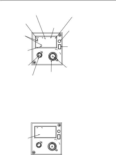
The KFS 594 (Figure 2-2) provides the pilot with access to 19 programmable channels plus a full 280,000 operating frequencies in the 2.0 to 29.9999 MHz range. In addition, all 245 ITU maritime radiotelephone network (public correspondence) channels have been stored in nonvolatile memory along with the appropriately paired transmit and receive frequencies. Thus, to call up a radiotelephone channel, the pilot need only select “423” for WOM in Ft. Lauderdale, Fla., for example, rather than having to program 4425.6 kHz as the transmit frequency and 4131.2 kHz as the receive frequency (see WOM channel/frequency chart, Figure 7-3). The KFS 594 is a miniature Gold Crown III style control display unit which uses electronic gas discharge readouts to display frequency and channel information. All necessary controls for operation of the KHF 950/990 system, including programming of all preset channels, are on the KFS 594.
The 19 channels can be easily programmed by the pilot on the ground or in the air, and the nonvolatile memory stores this information and the 245 ITU maritime radiotelephone channels even when the system is turned off.
Rev. 0 |
KHF 950/990 Pilots Guide |
2-3 |
Dec/96 |
Description
Pilot programmed |
Dash indicates unit |
With EMMISSION |
Smaller gas |
||||
channel number |
is in the PROGRAM |
MODE switch in |
discharge |
||||
appears in this area |
MODE. |
|
LSB*, USB or AM |
characters display |
|||
of the display when |
|
|
position, the first |
transmit indication. |
|||
using one of the 19 |
|
|
one or two digits |
|
|||
programmable |
|
|
(MHz) of the |
|
|||
channels. |
|
|
operating frequency |
Photocell dims |
|||
|
|
|
are displayed here. |
||||
|
|
|
display |
||||
Gas discharge |
|
|
|
|
|
||
|
|
|
|
|
automatically. |
||
readouts display all |
|
|
|
|
|
|
|
frequencies and |
|
1 |
|
|
|
||
preset channel |
|
|
|
STO (store) switch |
|||
CH |
|
|
|
|
|||
numbers. |
|
|
|
|
|||
|
|
M |
|
stored displayed |
|||
|
|
|
|
T H |
|
||
Last for digits (kHz) |
12 - 31 X Z |
|
frequency in memory. |
||||
1231 |
K |
|
When pressed |
||||
of operating |
S |
||||||
H |
simultaneously with |
||||||
frequency are |
Z |
T |
|||||
|
|
|
|
|
microphone push-to-talk |
||
display in this area |
|
HF |
|
|
|
||
VOL |
AM |
A3J TEL |
switch, transmits 1,000 |
||||
of the display with |
|
||||||
USB |
|
A3A |
Hz "operator attention" |
||||
EMISSION MODE |
|
|
|||||
OFF |
SQ |
|
|
|
tone as required by |
||
switch in LSB*, USB |
LSB |
|
|
|
|||
|
|
|
|
some Canadian |
|||
or AM position. |
|
|
|
|
|
||
|
|
|
|
|
radiotelephone stations. |
||
|
|
|
|
|
|
||
OFF/VOLUME knob |
|
|
|
|
|
|
|
(inner concentric) |
|
|
|
|
|
FREQUENCY/CHANNEL |
|
turns system on and |
|
|
|
|
|
CONTROL knob (inner |
|
adjusts audio |
|
EMMISSION MODE |
concentric) allows the pilot |
||||
volume. |
|
to perform a variety of |
|||||
SQUELCH knob |
switch (outer |
|
channel and frequency |
||||
(outer concentric) |
concentric) selects |
changing functions. |
|||||
helps reduce |
lower sideband |
|
Depressing switch causes |
||||
background noise |
(LSB), AM modes, |
flashing "cursor" to move to |
|||||
when not receiving |
and a choice of |
|
the digit that the pilot desires |
||||
a signal. |
either A3J or A3A in |
to change. Appropriate |
|||||
|
|
maritime |
|
|
frequency or channel is then |
||
|
|
radiotelephone |
|
selected with rotary action. |
|||
|
|
network channels. |
This switch also serves as |
||||
the clarifier function to adjust receive frequency and improve speech quality in single sideband operating mode.
Figure 2-2 KFS 594 Control Display Unit
KFS 594 in A3J (or A3A) Mode
KFS 594 in
A3J (or A3A) MODE
Mairitime radiotelephone ITU channel number appears in this area of the display when EMISSION MODE switch is in A3J or A3A position.
|
1 |
|
|
CH |
|
M |
|
|
|
|
|
|
|
H |
|
|
|
Z |
|
2236 |
K |
|
|
H |
S |
||
Z |
|||
|
|
|
T |
VOL |
HF |
A3J TEL |
|
AM |
|||
|
USB |
|
A3A |
|
SQ |
|
|
OFF |
|
|
|
LSB |
|
|
|
|
|
|
|
Figure 2-3 KFS 594 in A3J (or A3A) Mode
2-4 |
KHF 950/990 Pilots Guide |
Rev. 0 |
Dec/96 |
Description
KCU 951 CONTROL DISPLAY UNIT
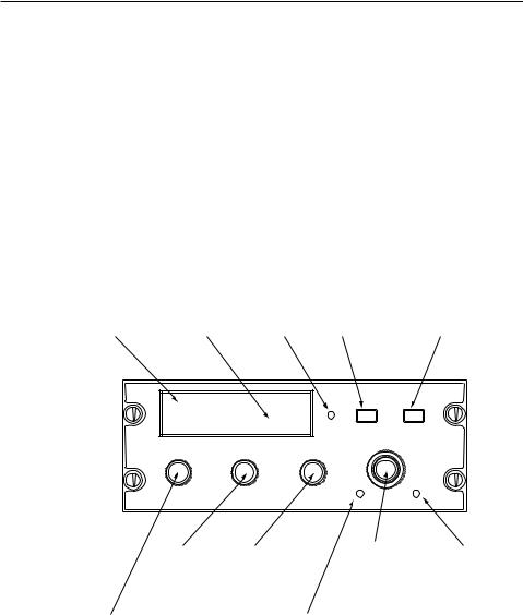
The KCU 951 (Figure 2-4) provides the pilot access to 99 programmable channels plus a full 280,000 operating frequencies in the 2.0 to 29.9999 MHz range. It provides semi-duplex capability through the 99 programmable channels to interface with maritime radiotelephone networks. A Dzus rail-mounted control display unit, the KCU 951, uses electronic gas discharge readouts to display frequency, channel and mode of operation. All necessary controls for operation of the KHF 950/990 system, including programming of all preset channels, are on the KCU 951. The 99 channels can be easily programmed by the pilot on the ground or in the air, and the nonvolatile memory stores this information even when the system is turned off.
|
Smaller gas |
|
EMMISSION MODE |
|
Gas discharge |
discharge |
|
switch selects lower |
FREQ/CHAN |
characters display |
|
sideband (LSB |
(frequency/channel) |
|
readouts display all |
emmision mode, |
Photocell |
where aproved), |
switch selects either |
frequncies and |
transmit indicator |
upper sideband |
direct tuning or |
|
preset channel |
and program mode |
dims display |
(USB) or AM |
preset channel |
numbers. |
indication. |
automatically. |
modes. |
operation. |
|
ı |
|
|
|
HF |
12345.6 99 |
|
||||
|
|
||||
LSB |
AM USB |
TX |
PGM |
MODE |
FREQ CHAN |
|
|
|
|
||
FREQ KHZ |
CHANNEL |
|
|
||
PULL |
|
|
|
|
|
|
|
|
OFF |
|
|
CLARIFIER |
SQUELCH |
|
VOLUME |
STO |
PGM |
|
|
|
|
||
SQUELCH knob |
OFF/VOLUME |
helps cut out |
knob turns |
background noise |
system on and |
when not |
adjusts audio |
receiving a signal. |
volume. |
CLARIFIER knob adjusts receive frequency to improve speech quality in a single sideband operating mode. Use of this control is only required when station-to-station frequency difference is significant.
Concentric |
PGM (program) |
Frequency/Channel |
switch permits pilot |
knobs set frequency |
to change frequncy |
or select preset |
and emission mode |
channel. |
of preset channel. |
STO (store) |
|
switch stores |
|
displayed |
|
frequency and |
|
emmission mode |
|
in memory. |
|
Figure 2-4 KCU 951 Control Display Unit
Rev. 0 |
KHF 950/990 Pilots Guide |
2-5 |
Dec/96 |
Loading...