


 Loading...
KAP 140
Bendix/King® Autopilot System
Pilot’s Guide
WARNING
The enclosed technical data is eligible for export under License Designation NLR and is to be used solely by the individual/organization to whom it is addressed. Diversion contrary to U.S. law is prohibited.
COPYRIGHT NOTICE
Copyright © 1998, 2002, 2005 Honeywell International Inc. All rights reserved.
Reproduction of this publication or any portion thereof by any means without the express written permission of Honeywell International Inc. is prohibited. For further information contact Aerospace Technical Publications; Honeywell; One Technology Center; 23500 West 105th Street; Olathe, Kansas 66061. Telephone: (913) 712-0400.
Revision History and Instructions
Manual |
KAP 140 Pilot’s Guide |
Revision |
3, November 2005 |
Part Number |
006-18034-0000 |
This revision changes CW to CCW on page 116.
R-1
Revision History and Instructions
Manual |
KAP 140 Pilot’s Guide |
Revision |
2, May 2002 |
Part Number |
006-18034-0000 |
This revision makes some of the changes for software version 03/01 more consistent throughout the Pilot’s Guide. The affected pages are 9, 12, 13, 55, 58, 83, 86 and 109.
R-2
Revision History and Instructions
Manual |
KAP 140 Pilot’s Guide |
Revision |
1, April 2002 |
Part Number |
006-18034-0000 |
This revision incorporates changes for software version 03/01.
R-3
Revision History and Instructions
Manual |
KAP 140 Pilot’s Guide |
Revision |
0, June 1998 |
Part Number |
006-18034-0000 |
This is the original version of this publication.
R-4

|
Table of Contents |
|
Introduction . . . . . . . . . . . . . . |
. . . . . . . . . . . . . . . . . . . . . . . . . . . . . . . . . . . . . |
. .1 |
General Description . . . . . . |
. . . . . . . . . . . . . . . . . . . . . . . . . . . . . . . . . . . . . . |
.2 |
KAP 140 Single Axis Autopilot System . . . . . . . . . . . . . . . . . . . . . . . . . . . |
.2 |
|
KAP 140 Two Axis Autopilot System . . . . . . . . . . . . . . . . . . . . . . . . . . . . . |
.2 |
|
KAP 140 Two Axis/Altitude Preselect Autopilot System . . . . . . . . . . . . . . |
.2 |
|
System Integration . . . . . . . |
. . . . . . . . . . . . . . . . . . . . . . . . . . . . . . . . . . . . . . |
.4 |
Power Application and Preflight Tests . . . . . . . . . . . . . . . . . . . . . . . . . . . . . |
.8 |
|
KAP 140 Single Axis Operation . . . . . . . . . . . . . . . . . . . . . . . . . . . . . . . . . . . |
.9 |
|
System Operating Modes . . |
. . . . . . . . . . . . . . . . . . . . . . . . . . . . . . . . . . . . . . |
12 |
Wing Leveler (ROL) Mode . . . . . . . . . . . . . . . . . . . . . . . . . . . . . . . . . . . . . |
12 |
|
Heading Select (HDG) Mode . . . . . . . . . . . . . . . . . . . . . . . . . . . . . . . . . . . |
13 |
|
Navigation (NAV) Mode Using a DG from HDG Mode |
|
|
(45° Intercept) . . . . . . . . . |
. . . . . . . . . . . . . . . . . . . . . . . . . . . . . . . . . . . . . . |
14 |
Navigation (NAV) Mode Using a DG from ROL Mode |
|
|
(All Angle Intercept) . . . . |
. . . . . . . . . . . . . . . . . . . . . . . . . . . . . . . . . . . . . . |
16 |
Approach (APR) Mode Using a DG from HDG Mode |
|
|
(45° Intercept) . . . . . . . . . |
. . . . . . . . . . . . . . . . . . . . . . . . . . . . . . . . . . . . . . |
20 |
Approach (APR) Mode Using a DG from ROL Mode |
|
|
(All Angle Intercept) . . . . |
. . . . . . . . . . . . . . . . . . . . . . . . . . . . . . . . . . . . . . |
22 |
Approach (APR) Mode Using an HSI . . . . . . . . . . . . . . . . . . . . . . . . . . . . . |
24 |
|
Back Course (REV) Mode Using a DG from HDG Mode |
|
|
(45° Intercept) . . . . . . . . . |
. . . . . . . . . . . . . . . . . . . . . . . . . . . . . . . . . . . . . . |
26 |
Back Course (REV) Mode Using a DG from ROL Mode |
|
|
(All Angle Intercept) . . . . |
. . . . . . . . . . . . . . . . . . . . . . . . . . . . . . . . . . . . . . |
28 |
Back Course (REV) Mode Using an HSI . . . . . . . . . . . . . . . . . . . . . . . . . . |
30 |
|
Operations With The KAP 140 . . . . . . . . . . . . . . . . . . . . . . . . . . . . . . . . . . . . |
32 |
|
Takeoff And Climb To Assigned Altitude . . . . . . . . . . . . . . . . . . . . . . . . . . . |
32 |
|
GPS Capture Using DG . . |
. . . . . . . . . . . . . . . . . . . . . . . . . . . . . . . . . . . . . . |
34 |
GPS Capture Using HSI . |
. . . . . . . . . . . . . . . . . . . . . . . . . . . . . . . . . . . . . . |
36 |
Outbound On Front Course For Procedure Turn To LOC Approach |
|
|
Using DG . . . . . . . . . . . . . |
. . . . . . . . . . . . . . . . . . . . . . . . . . . . . . . . . . . . . . |
38 |
Outbound On Front Course For Procedure Turn To LOC Approach |
|
|
Using HSI . . . . . . . . . . . . . |
. . . . . . . . . . . . . . . . . . . . . . . . . . . . . . . . . . . . . . |
40 |
Front Course LOC Approach Using DG . . . . . . . . . . . . . . . . . . . . . . . . . . . |
42 |
|
Front Course LOC Approach Using HSI . . . . . . . . . . . . . . . . . . . . . . . . . . |
44 |
|
Outbound on GPS Approach Using DG . . . . . . . . . . . . . . . . . . . . . . . . . . . |
46 |
|
Outbound on GPS Approach Using HSI . . . . . . . . . . . . . . . . . . . . . . . . . . . |
48 |
|
Inbound on GPS Approach Using DG . . . . . . . . . . . . . . . . . . . . . . . . . . . . . |
50 |
|
Inbound on GPS Approach Using HSI . . . . . . . . . . . . . . . . . . . . . . . . . . . . |
52 |
|
KAP 140 Two Axis Operation . . . . . . . . . . . . . . . . . . . . . . . . . . . . . . . . . . . . . |
55 |
|
System Operating Modes . . |
. . . . . . . . . . . . . . . . . . . . . . . . . . . . . . . . . . . . . . |
57 |
Vertical Speed (VS) Mode |
. . . . . . . . . . . . . . . . . . . . . . . . . . . . . . . . . . . . . |
58 |
Altitude Hold (ALT) Mode |
. . . . . . . . . . . . . . . . . . . . . . . . . . . . . . . . . . . . . . |
59 |
Operations With The KAP 140 . . . . . . . . . . . . . . . . . . . . . . . . . . . . . . . . . . . . |
60 |
|
Takeoff And Climb To Assigned Altitude . . . . . . . . . . . . . . . . . . . . . . . . . . . |
60 |
|
GPS Capture Using DG . . |
. . . . . . . . . . . . . . . . . . . . . . . . . . . . . . . . . . . . . . |
62 |
Rev. 0 |
|
|
Jun/98 |
KAP 140 AUTOPILOT SYSTEM |
i |

Table of Contents
GPS Capture Using HSI . . . . . . . . . . . . . . . . . . . . . . . . . . . . . . . . . . . . . . .64
Outbound On Front Course For Procedure Turn To ILS Approach
Using DG . . . . . . . . . . . . . . . . . . . . . . . . . . . . . . . . . . . . . . . . . . . . . . . . . . .66
Outbound On Front Course For Procedure Turn To ILS Approach
Using HSI . . . . . . . . . . . . . . . . . . . . . . . . . . . . . . . . . . . . . . . . . . . . . . . . . . .68 Front Course ILS Approach Using DG . . . . . . . . . . . . . . . . . . . . . . . . . . . .70 Front Course ILS Approach Using HSI . . . . . . . . . . . . . . . . . . . . . . . . . . .72 Outbound on GPS Approach Using DG . . . . . . . . . . . . . . . . . . . . . . . . . . .74 Outbound on GPS Approach Using HSI . . . . . . . . . . . . . . . . . . . . . . . . . . .76 Inbound on GPS Approach Using DG . . . . . . . . . . . . . . . . . . . . . . . . . . . . .78 Inbound on GPS Approach Using HSI . . . . . . . . . . . . . . . . . . . . . . . . . . . .80
KAP 140 Two Axis with Altitude Preselect Operation . . . . . . . . . . . . . . . |
. .83 |
|
|
System Operating Modes . . . . . . . . . . . . . . . . . . . . . . . . . . . . . . . . . . . . . . |
. .86 |
|
Vertical Speed (VS) Mode . . . . . . . . . . . . . . . . . . . . . . . . . . . . . . . . . . . . |
.86 |
|
Altitude Hold (ALT) Mode . . . . . . . . . . . . . . . . . . . . . . . . . . . . . . . . . . . . . |
.87 |
|
Altitude Alerting and Preselect . . . . . . . . . . . . . . . . . . . . . . . . . . . . . . . . . . . |
.88 |
|
Altitude Alerter . . . . . . . . . . . . . . . . . . . . . . . . . . . . . . . . . . . . . . . . . . . . . . |
.88 |
|
Altimeter Setting . . . . . . . . . . . . . . . . . . . . . . . . . . . . . . . . . . . . . . . . . . . . |
.88 |
|
Altitude Preselect . . . . . . . . . . . . . . . . . . . . . . . . . . . . . . . . . . . . . . . . . . . |
.89 |
|
Voice Messaging . . . . . . . . . . . . . . . . . . . . . . . . . . . . . . . . . . . . . . . . . . . . . |
.89 |
|
Operations With The KAP 140 . . . . . . . . . . . . . . . . . . . . . . . . . . . . . . . . . . . |
.90 |
|
Takeoff And Climb To Assigned Altitude . . . . . . . . . . . . . . . . . . . . . . . . . . |
.90 |
|
GPS Capture Using DG . . . . . . . . . . . . . . . . . . . . . . . . . . . . . . . . . . . . . . . |
.92 |
|
GPS Capture Using HSI . . . . . . . . . . . . . . . . . . . . . . . . . . . . . . . . . . . . . . |
.94 |
|
Outbound On Front Course For Procedure Turn To ILS Approach |
|
|
Using DG . . . . . . . . . . . . . . . . . . . . . . . . . . . . . . . . . . . . . . . . . . . . . . . . . . |
.96 |
|
Outbound On Front Course For Procedure Turn To ILS Approach |
|
|
Using HSI . . . . . . . . . . . . . . . . . . . . . . . . . . . . . . . . . . . . . . . . . . . . . . . . . . |
.98 |
|
Front Course ILS Approach Using DG . . . . . . . . . . . . . . . . . . . . . . . . . . . |
100 |
|
Front Course ILS Approach Using HSI . . . . . . . . . . . . . . . . . . . . . . . . . . |
102 |
|
Outbound on GPS Approach Using DG . . . . . . . . . . . . . . . . . . . . . . . . . . |
104 |
|
Outbound on GPS Approach Using HSI . . . . . . . . . . . . . . . . . . . . . . . . . . |
106 |
|
Inbound on GPS Approach Using DG . . . . . . . . . . . . . . . . . . . . . . . . . . . . |
108 |
|
Inbound on GPS Approach Using HSI . . . . . . . . . . . . . . . . . . . . . . . . . . . |
110 |
KCS 55A Compass System . . . . . . . . . . . . . . . . . . . . . . . . . . . . . . . . . . . . . . |
113 |
|
|
KI 525A Indicator . . . . . . . . . . . . . . . . . . . . . . . . . . . . . . . . . . . . . . . . . . . . . |
114 |
|
Description of Indicator and Display Functions . . . . . . . . . . . . . . . . . . . . . . |
114 |
|
Slaving Meter ( KA 51B) . . . . . . . . . . . . . . . . . . . . . . . . . . . . . . . . . . . . . . . . |
116 |
|
KMT 112 Magnetic Slaving Transmitter . . . . . . . . . . . . . . . . . . . . . . . . . . . . |
117 |
|
KG 102A Directional Gyro . . . . . . . . . . . . . . . . . . . . . . . . . . . . . . . . . . . . . . |
117 |
|
Abnormal Circumstances . . . . . . . . . . . . . . . . . . . . . . . . . . . . . . . . . . . . . . . |
119 |
|
Flight Procedures with the KCS 55A . . . . . . . . . . . . . . . . . . . . . . . . . . . . . . |
120 |
Abnormal Procedures . . . . . . . . . . . . . . . . . . . . . . . . . . . . . . . . . . . . . . . . . . |
127 |
|
|
Autopilot Malfunction . . . . . . . . . . . . . . . . . . . . . . . . . . . . . . . . . . . . . . . . . . |
127 |
|
|
Rev. 0 |
ii |
KAP 140 AUTOPILOT SYSTEM |
Jun/98 |

Introduction
Introduction
The KAP 140 Autopilot System is a rate based digital autopilot system offering smooth performance and enhanced features found only in more expensive autopilots. The first of its type developed by Honeywell, this system brings digital technology and reliability into the light aircraft cockpit.
It is also significant that the KAP 140 series autopilots have been designed from their inception to interface with the Silver Crown package of products. Consider the advantage of having your avionics working together as an integrated system rather than as a group of components built by several manufactures.
Your new KAP 140 roll axis features include wing leveler, heading select, and VOR/LOC intercept and tracking. The KAP 140 can also be coupled to GPS and RNAV receivers as well. Roll rate information is derived from the turn coordinator. Pitch axis features include vertical speed, glideslope and altitude hold along with the optional altitude preselect. Pitch information is derived from a pressure sensor and accelerometer. The KAP 140 Autopilot System operates independent of the aircraft’s artificial horizon. Therefore, the autopilot retains roll stabilization and all vertical modes in the event of vacuum system failure.
Internal monitors keep constant track of the KAP 140’s status and provide for automatic shutdown of the autopilot or trim system in the event of a malfunction. In addition to reliability, the KAP 140 is designed to be easily maintained in the field. Qualified Honeywell Service Centers are located around the world to provide assistance whenever necessary.
To fully realize the capability of your new panel mount digital autopilot system, you must understand the performance capabilities and basic operational requirements of the system. This pilot’s guide provides information to aid in this and is divided up into six sections. The first section provides general familiarization of each autopilot system including the associated panel mounted displays. The second section describes the KAP 140 Single Axis Autopilot System. The third section describes the KAP 140 Two Axis Autopilot System. The fourth section describes the KAP 140 Two Axis/Altitude Preselect Autopilot System. The fifth section describes the optional KCS 55A slaved compass system. The Sixth section describes abnormal procedures.
Rev. 1 |
KAP 140 AUTOPILOT SYSTEM |
1 |
Apr/02 |
Introduction
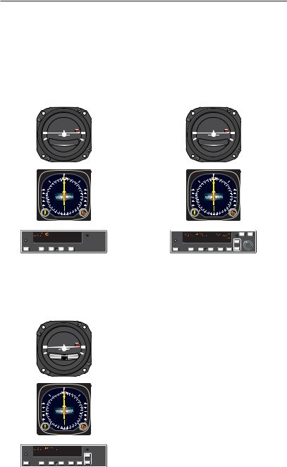
General Description
KAP 140 Single Axis
Autopilot System
The KAP 140 Single Axis system is an entry level digital panel-mount autopilot, offering lateral modes only with an electric trim option.
KAP 140 Two Axis/Altitude
Preselect Autopilot System
The KAP 140 Two Axis system provides both lateral and vertical modes with altitude preselect.
D.C. ELEC.
TURN COORDINATOR
L  R
R
|
|
|
2 MIN. |
|
|
|
|
NO PITCH |
|
|
|
|
|
INFORMATION |
|
||
|
|
6 |
E |
12 |
|
|
|
|
|
||
GS |
|
|
|
GS |
|
|
3 |
|
|
|
15 |
|
|
|
|
|
|
|
N |
|
|
|
S |
|
|
|
|
|
|
|
33 |
|
|
|
21 |
|
|
0 |
|
|
|
|
|
|
|
|
|
|
|
3 |
W |
24 |
|
|
|
|
|
||
|
|
|
|
|
|
ı
G
KAP 140
AP |
HDG |
NAV |
APR |
REV |
KAP 140 Two Axis
Autopilot System
The KAP 140 Two Axis system provides both lateral and vertical modes.
D.C. ELEC.
TURN COORDINATOR
L |
|
|
R |
|
2 MIN. |
|
|
|
NO PITCH |
|
|
|
INFORMATION |
|
|
|
N |
3 |
|
GS |
33 |
6 |
GS |
|
30 |
|
E |
|
W |
|
12 |
|
24 |
15 |
|
|
21 |
S |
|
ı
G
KAP 140
|
|
|
|
|
|
UP |
AP |
HDG |
NAV |
APR |
REV |
ALT |
DN |
D.C. ELEC.
TURN COORDINATOR
L  R
R
2 MIN.
NO PITCH
INFORMATION
|
|
|
6 |
E |
12 |
|
|
GS |
|
|
|
GS |
|
|
|
3 |
|
|
|
15 |
|
|
|
|
|
|
|
|
|
N |
|
|
|
S |
|
|
|
|
|
|
|
|
|
33 |
|
|
|
21 |
|
|
|
0 |
|
|
|
|
|
|
|
|
|
|
|
|
|
3 |
W |
24 |
|
|
|
|
|
|
||
|
|
|
|
|
|
|
|
|
|
|
ı |
|
|
G |
|
|
|
|
|
|
KFC 140 |
|
|
|
|
|
ARM BARO |
|
|
|
|
|
|
UP |
AP |
HDG NAV |
APR |
REV ALT DN |
|||
2 |
KAP 140 AUTOPILOT SYSTEM |
Rev. 1 |
Apr/02 |
Introduction
|
KAP 140 |
KAP 140 |
KAP 140 |
|
Two Axis Alt. |
Two Axis |
Single Axis |
|
Preselect |
|
|
HSI |
Optional |
Optional |
Optional |
DG |
Standard |
Standard |
Standard |
Turn Coordinator |
Standard |
Standard |
Standard |
Automatic Electric Elevator Trim |
Optional |
Optional |
|
Manual Electric Trim |
Optional |
Optional |
|
FUNCTIONS/MODES |
|
|
|
|
|
|
|
ALT Hold (ALT) |
Yes |
Yes |
|
ALT Preselect/ALERT |
Yes |
|
|
Heading Select (HDG) |
Yes |
Yes |
Yes |
NAV (VOR/RNAV/GPS) |
Yes |
Yes |
Yes |
Approach (APR) |
Yes |
Yes |
Yes |
Glideslope (GS) |
Yes |
Yes |
|
Back Course (REV) |
Yes |
Yes |
Yes |
Control Wheel Steering (CWS) |
Optional |
Optional |
Optional |
Vertical Speed Hld |
Yes |
Yes |
|
Auto Capture |
Yes |
Yes |
Yes |
Auto Track |
Yes |
Yes |
Yes |
All Angle Intercept |
Standard (with |
Standard (with |
Standard (with |
|
DG or optional |
DG or optional |
DG or optional |
|
HSI) |
HSI) |
HSI) |
Auto 45-degree Intercept |
Standard |
Standard |
Standard |
|
(with DG only) |
(with DG only) |
(with DG only) |
TEST |
|
|
|
|
|
|
|
Manual and Auto Trim Monitor |
Both |
Both |
Both |
Acceleration Monitor |
Yes |
Yes |
|
KAP 140 System Capabilities
Rev. 1 |
KAP 140 AUTOPILOT SYSTEM |
3 |
Apr/02 |

Introduction
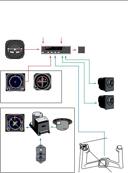
System Integration
The individual system diagrams on pages 5, 6, and 7 show the components and their relationship in typical KAP 140 Single Axis, KAP 140 Two Axis, and KAP 140 Two Axis/Altitude Preselect systems. The actual components on individual systems may vary slightly in order to optimize certification and installation requirements.
Each system has a number of inputs: sensor outputs are shown in red; combination inputs are shown in blue; display outputs are shown in orange; and aircraft control shown in green. The systems diagrams reflect that the KAP 140 systems control both pitch and roll axes of the aircraft.
4 |
KAP 140 AUTOPILOT SYSTEM |
Rev. 1 |
Apr/02 |
Introduction
|
|
|
Middle |
VOR/LOC/RNAV/ |
|||
|
|
|
Marker |
|
GPS Deviation |
||
D.C. ELEC. |
|
|
|
|
|
|
|
TURN COORDINATOR |
|
G |
|
|
|
|
|
|
KAP 140 |
|
|
|
|
||
|
|
|
|
|
|
|
TRIM |
L |
R |
|
|
|
|
|
FAIL |
|
AP |
|
HDG |
NAV |
APR REV |
||
2 MIN. |
|
|
|
|
|
|
|
NO PITCH |
|
|
|
|
|
|
|
INFORMATION |
|
|
|
|
|
|
|
Turn Coordinator |
|
|
|
|
|
|
|
AIR |
|
|
|
|
|
|
|
|
|
|
N |
3 |
|
|
|
N |
|
|
33 |
|
|
|
|
3 |
|
|
|
|
|
|
|
33 |
30 |
A |
TO |
6 |
|
|
|
|
|
|
N |
|
|
|
|
30 |
6 |
|
V |
|
|
|
|
|
|
GS |
|
|
|
|
|
W |
E |
W |
|
|
E |
|
|
24 |
12 |
24 |
|
FR |
12 |
|
|
|
|
|
|
|
|
|
|
|
21 |
S |
15 |
|
|
21 |
|
|
|
|
|
OBS |
15 |
||
|
|
|
|
|
|
S |
|
PUSH |
|
|
|
PU S |
|
ı |
|
|
|
|
|
|
|
||
Directional Gyro |
KI 204 or other Course |
||||||
|
|
|
|
|
Deviation Indicator |
||
|
|
|
|
|
OR |
|
|
|
|
|
|
|
|
|
KG102A |
|
|
|
|
|
|
|
Slaved DG |
|
NAV |
N |
HDG |
|
|
|
|
|
33 |
3 |
|
|
|
|
|
GS |
|
GS |
|
|
|
||
0 |
|
|
|
|
|
||
3 |
|
|
6 |
|
|
KCS 305 |
|
|
|
|
|
|
|
||
W |
|
|
|
E |
|
ı |
|
4 |
|
2 |
1 |
|
|
|
|
|
2 |
|
|
|
|
|
|
|
12 |
|
1 |
|
|
|
|
|
S |
5 |
|
|
|
|
|
|
|
|
|
|
|
|
|
ı |
|
|
KI 525A Pictorial |
KMT 112 |
|
Flux Detector |
||
Navigation Indicator |
||
|
KC 140 Single Axis Computer/Controller/ Annunciator contains computer functions, mode control buttons,
and annunciations in a single unit.
KS 271C Roll Servo
KS 272C Pitch Trim
Servo (Optional)
Autopilot
Disconnect/
Trim Interrupt
(Optional)
KCS 55A Slaved
Compass System
(Optional)
- |
+ |
AUTO |
MAN |
CCW |
CW |
KA 51B
Slaving Accessory
Control |
Manual |
WheelSteering |
Electrical Trim |
(Optional) |
(Optional) |
KAP 140 Single Axis System Diagram
Rev. 1 |
KAP 140 AUTOPILOT SYSTEM |
5 |
Apr/02 |
Introduction
|
|
|
VOR/LOC/RNAV/ |
|
Static |
|||||
|
|
|
GPS Deviation |
|
Pressure |
|||||
|
|
Glideslope |
|
|
Middle |
|
||||
|
|
Deviation |
|
Marker |
|
|||||
D.C. ELEC. |
|
|
|
|
|
|
|
|
|
|
|
|
|
G |
|
|
|
|
|
TRIM |
|
TURN COORDINATOR |
|
KAP 140 |
|
|
|
|
|
|||
|
|
|
|
|
|
|
|
|
|
|
|
|
|
|
|
|
|
|
|
DN |
FAIL |
L |
R |
|
AP |
|
HDG |
NAV |
APR |
REV ALT |
UP |
|
|
|
|
|
|||||||
2 MIN. |
|
|
|
|
|
|
|
|
|
|
NO PITCH |
|
|
|
|
|
|
|
|
|
|
INFORMATION |
|
|
|
|
|
|
|
|
|
|
Turn Coordinator |
|
|
|
|
|
|
|
|
|
|
AIR |
|
|
|
|
|
|
|
|
|
|
|
|
|
N |
3 |
|
|
|
|
|
|
N |
|
33 |
|
|
|
|
|
|
|
|
3 |
|
|
|
|
|
|
|
|
|
|
33 |
30 |
A |
TO |
6 |
|
|
|
|
|
|
|
|
|
N |
|
|
|
|
|
|
|
30 |
6 |
GS |
V |
|
|
|
|
|
|
|
|
|
|
|
|
|
|
|
|
||
W |
E |
W |
|
|
E |
|
|
|
|
|
24 |
12 |
24 |
|
FR |
12 |
|
|
|
|
|
|
|
|
|
|
|
|
|
|
|
|
|
21 |
S |
15 |
|
|
21 |
|
|
|
|
|
OBS |
15 |
||
|
|
|
|
|
|
S |
|
PUSH |
|
|
|
PU S |
|
ı |
|
Directional Gyro |
KI 204 or other Course |
||||||
|
|
|
|
|
Deviation Indicator |
||
|
|
|
|
|
(not included) |
||
|
|
|
|
|
OR |
|
|
|
|
|
|
|
|
|
KG102A |
|
|
|
|
|
|
|
Slaved DG |
|
NAV |
N |
HDG |
|
|
|
|
GS |
33 |
|
3 |
GS |
|
|
|
0 |
|
|
|
|
|
||
3 |
|
6 |
|
|
KCS 305 |
||
|
|
|
|
|
|
||
W |
|
|
|
E |
|
ı |
|
4 |
|
2 |
1 |
|
|
|
|
|
2 |
|
|
|
|
|
|
|
12 |
|
1 |
|
|
|
|
|
S |
5 |
|
|
|
|
|
|
|
|
|
|
|
|
|
ı |
|
|
KI 525A Pictorial |
KMT 112 |
|
Flux Detector |
||
Navigation Indicator |
||
|
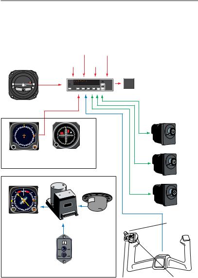
KC 140 Two Axis Computer/ Controller/ Annunciator contains computer functions, mode control buttons, and annunciations in a single unit. Also contains static pressure sensor and accelerometer.
KS 271C Roll Servo
KS 270C Pitch Servo
KS 272C Pitch Trim Servo
Autopilot
Disconnect/
Trim Interrupt
KCS 55A Slaved
Compass System
(Optional)
- |
+ |
AUTO |
MAN |
CCW |
CW |
KA 51B
Slaving Accessory
Control |
Manual |
WheelSteering |
Electrical Trim |
(optional) |
|
KAP 140 Two Axis System Diagram
6 |
KAP 140 AUTOPILOT SYSTEM |
Rev. 1 |
Apr/02 |
Introduction
D.C. ELEC.
TURN COORDINATOR
L  R
R
2 MIN.
NO PITCH
INFORMATION
Turn Coordinator
|
AIR |
|
|
N |
|
33 |
3 |
|
30 |
6 |
|
W |
E |
|
24 |
12 |
|
21 |
15 |
|
S |
||
|
PUSH
P
U S
Directional Gyro
|
|
VOR/LOC/ |
|
|
|
|
|
Baro |
RNAV/ |
|
Encoding |
|
|
Setting |
GPS |
|
Altimeter |
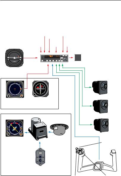
KC 140 Two Axis with |
||
|
|
Deviation |
|
|
|
Altitude Preselect |
|
|
|
|
|
|
|
Glideslope |
Middle |
|
|
Static |
Computer/Controller/ |
|
Deviation |
Marker |
|
|
Pressure |
Annunciator |
|
|
|
|
|
|
|
contains computer |
|
|
|
|
|
|
functions, mode |
|
|
|
|
|
|
control buttons, |
|
G |
|
|
|
TRIM |
and annunciations |
|
KFC 140 |
|
|
ARM BARO |
||
|
|
|
UP |
|
FAIL |
in a single unit. Also |
|
AP |
HDG NAV APR REV ALT |
DN |
|
|
|
|
|
|
|
|
|
contains static pressure |
|
|
|
|
|
|
sensor and accelerometer. |
|
|
|
|
|
|
KS 271C Roll Servo |
|
N |
|
|
|
|
|
33 |
3 |
|
|
|
|
|
30 |
A |
TO |
|
|
N |
|
6 |
|
V |
|
|
|
GS |
|
|
W |
|
|
E |
24 |
|
FR |
12 |
OBS 21 |
15 |
|
|
S |
|
|
ı |
|
KI 204 or other Course |
KS 270C Pitch Servo |
|
|
||
Deviation Indicator |
|
|
(not included) |
|
|
OR
KG102A |
KS 272C Pitch Trim Servo |
Slaved DG |
|
|
NAV |
N |
HDG |
|
|
33 |
3 |
|
|
GS |
|
GS |
||
0 |
|
|
||
3 |
|
|
6 |
|
|
|
|
|
|
W |
|
|
|
E |
4 |
|
2 |
1 |
|
|
2 |
|
|
|
|
12 |
|
1 |
|
|
S |
5 |
|
|
|
|
|
|
|
ı
KI 525A Pictorial
Navigation Indicator
KCS 305
ı
KMT 112 |
Autopilot |
Flux Detector |
Disconnect/ |
|
Trim Interrupt |
KCS 55A Slaved
Compass System
(Optional)
- |
+ |
AUTO |
MAN |
CCW |
CW |
|
KA 51B |
|
|
Slaving Accessory |
|
|
Control |
Manual |
|
WheelSteering |
Electrical Trim |
|
(optional) |
|
|
KAP 140 Two Axis/Altitude Preselect System Diagram |
|
Rev. 1 |
KAP 140 AUTOPILOT SYSTEM |
7 |
Apr/02 |
||
Introduction
Power Application and Preflight Tests
G
KAP 140
AP |
HDG |
NAV |
APR |
REV |
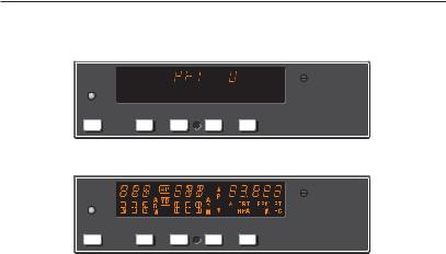
KAP 140 Preflight Test
G
KAP 140
AP |
HDG |
NAV |
APR |
REV |
KAP 140 Preflight Test Complete
A preflight test is performed upon power application to the computer. This test is a sequence of internal checks that validate proper system operation prior to allowing autopilot engagement. The preflight test (PFT) sequence is indicated by “PFT” with an increasing number for the sequence steps. Successful completion of self test is identified by all display segments being illuminated (Display Test) and the disconnect tone sounding.
For two-axis units only:
NOTE: Following the preflight test, the red P warning on the face of the autopilot may illuminate indicating that the pitch axis cannot be engaged. This condition should be temporary, lasting no more than 30 seconds. The P will extinguish and normal operation will be available.
NOTE: The red P warning may illuminate when the autopilot is not engaged. This can occur when autopilot G limits have been exceeded during turbulence or aircraft maneuvering. Autopilot engagement is locked out during red P illumination.
If power to the autopilot is cycled in flight (i.e. through the autopilot circuit breaker for instance) it is possible that a 5 minute delay may be necessary prior to autopilot engagement to allow the pitch axis accelerometer circuit to stabilize. Engagement prior to stabilization may result in mildly erratic pitch axis behavior.
8 |
KAP 140 AUTOPILOT SYSTEM |
Rev. 1 |
Apr/02 |

Single Axis Operation
KAP 140 Single Axis Operation
The KAP 140 is a high-performance digital, panel-mounted autopilot system for light aircraft.
7 8
G
KAP 140
P R
AP |
HDG |
NAV |
APR |
REV |
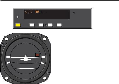
Single-axis Flight Control Computer
G
KAP 140
P R
AP |
HDG |
NAV |
APR |
REV |
1 |
2 |
3 |
4 |
Full Single-axis KAP 140 Display
1.AUTOPILOT ENGAGE/DISENGAGE (AP) BUTTON - When pushed, engages autopilot if all logic conditions are met. The autopilot will engage in the basic roll (ROL) mode which functions as a wing leveler. When pressed again, will disengage the autopilot. For software version 03/01 and later, the AP button must be pressed and held for 0.25 seconds to engage the autopilot.
2.ROLL AXIS (R) ANNUNCIATION - When illuminated, indicates failure of the roll axis and will disengage the autopilot and not allow engagement.
3.HEADING (HDG) MODE SELECTOR BUTTON - When pushed, will select the Heading mode, which commands the airplane to turn to
5 6
and maintain the heading selected by the heading bug on either the DG or HSI. A new heading may be selected at any time and will result in the airplane turning to the new heading. Button can also be used to toggle between HDG and ROL modes. This button will engage the autopilot in units with software prior to software version 03/01.
4. NAVIGATION (NAV) MODE SELECTOR BUTTON - When pushed, will arm the navigation mode. The mode provides automatic beam capture and tracking of VOR, LOC or GPS as selected for presentation on the HSI or CDI. NAV mode is recommended for enroute navigation tracking.
Rev. 2 |
KAP 140 AUTOPILOT SYSTEM |
9 |
May/02 |

Single Axis Operation
5.APPROACH (APR) MODE SELECTOR BUTTON - When pushed, will arm the Approach mode. This mode provides automatic beam capture and tracking of VOR, GPS and LOC, as selected for presentation on the HSI or CDI. APR mode is recommended for instrument approaches.
6.BACK COURSE APPROACH (REV) MODE SELECTOR BUTTON - When pushed, will arm the Back Course approach mode. This mode functions similarly to the approach mode except that the autopilot response to LOC signals is reversed.
7.ROLL MODE DISPLAY - Displays the active and armed roll modes (ROL, HDG, NAV ARM, NAV, APR ARM, APR, REV ARM, REV). Also displayed will be flashing AP annunciation (5 seconds) at each autopilot disconnect accompanied by an aural tone (for 2 seconds).
8.AUTOPILOT ENGAGED (AP) ANNUNCIATION - Illuminates whenever the autopilot is engaged. Flashes during pilot initiated or automatic disengagement. Only applicable for software versions 03/01 or later.
10 |
KAP 140 AUTOPILOT SYSTEM |
Rev. 1 |
Apr/02 |

Single Axis Operation
This page intentionally left blank
Rev. 1 |
KAP 140 AUTOPILOT SYSTEM |
11 |
Apr/02 |
Single Axis Operation
System Operating Modes
G
KAP 140
AP |
HDG |
NAV |
APR |
REV |
D.C. ELEC.
TURN COORDINATOR
L  R
R
2 MIN.
NO PITCH
INFORMATION
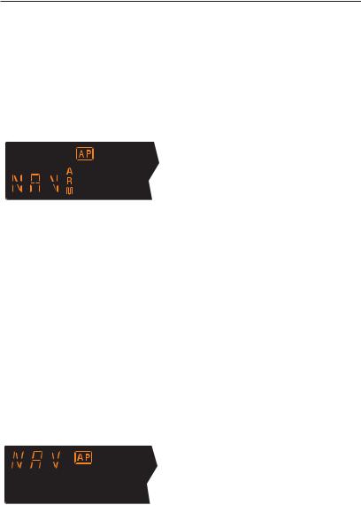
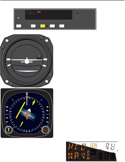
Wing Leveler (ROL) Mode
In the roll mode, the autopilot maintains wings level flight.
1. Engage autopilot - Press AP. For software version 03/01 and later, the AP button must be pressed and held for 0.25 seconds to engage the autopilot.
NOTE: The KAP 140 engages into ROL mode as a default.
12 |
KAP 140 AUTOPILOT SYSTEM |
Rev. 2 |
May/02 |
Single Axis Operation
G
KAP 140
AP |
HDG |
NAV |
APR |
REV |
D.C. ELEC.
TURN COORDINATOR
L  R
R
2 MIN.
NO PITCH
INFORMATION
|
|
N |
3 |
|
33 |
|
|
30 |
|
|
|
|
|
6 |
|
|
|
|
|
W |
|
|
E |
|
|
|
|
24 |
|
|
12 |
|
21 |
|
15 |
|
S |
|
|
|
|
|
PUSH
PU SH
|
33 |
N |
3 |
|
|
||
GS |
|
GS |
|
|
|
||
30 |
|
|
6 |
|
|
|
|
W |
|
|
E |
24 |
|
|
12 |
|
|
|
|
|
21 |
S |
15 |
|
|
||
|
|
|
ı
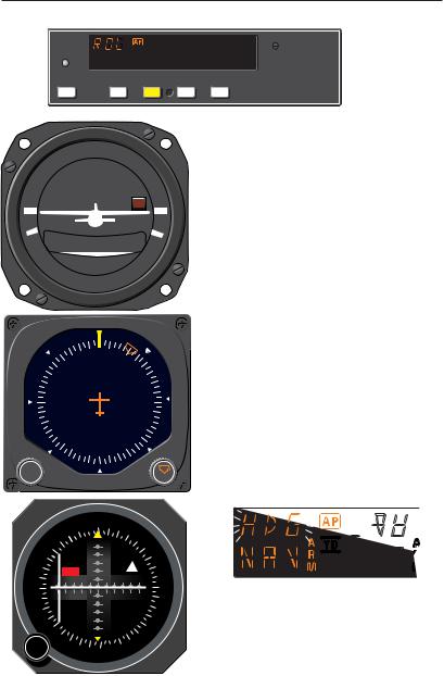
Heading Select (HDG) Mode
In the heading mode, the autopilot will fly a selected heading. The following steps should be taken to operate in the heading mode:
1.Move the heading “bug” to the desired heading on the DG or HSI using the Heading Select knob.
2.Engage autopilot - Press AP. For software version 03/01 and later, the AP button must be pressed and held for 0.25 seconds to engage the autopilot.
3.Depress the HDG button on the KAP 140 to engage the heading select mode. The autopilot will turn the aircraft in the shortest direction to intercept and fly the heading.
4.If you move the heading “bug” again while the heading select mode is engaged, the autopilot will immediately turn the aircraft in the direction of the newly selected heading.
5.Press HDG button again and the autopilot will return to the ROL mode.
Rev. 2 |
KAP 140 AUTOPILOT SYSTEM |
13 |
May/02 |

Single Axis Operation
G
KAP 140
AP |
HDG |
NAV |
APR |
REV |
D.C. ELEC.
TURN COORDINATOR
L  R
R
2 MIN.
NO PITCH
INFORMATION
3 |
6 |
|
E |
||
|
||
N |
12 |
|
33 |
15 |
|
|
||
30 |
S |
|
|
||
W |
21 |
|
|
24 |
PUSH
PU SH
|
E |
12 |
|
|
|
|
|
|
|
|
6 |
|
|
15 |
|
|
N |
|
|
|
|
TO |
|
|
|
|
A |
|
|
3 |
GS |
V |
|
|
|
|
S |
||
|
|
|
||
|
|
|
|
|
N |
|
|
|
21 |
|
|
|
FR |
|
|
|
|
|
|
33 |
24 |
|
|
|
OBS |
30 |
W |
ı
Navigation (NAV) Mode Using a DG from HDG Mode
(45° Intercept)
In the navigation (NAV) mode, the autopilot intercepts and tracks VOR/RNAV and GPS courses.
To arm NAV mode (with the KAP 140 currently in the HDG mode):
1.Select the desired frequency for VOR or RNAV. For GPS, verify the desired waypoint or destination.
2.OBS Knob - SELECT desired course.
3.NAV Mode Selector Button - PRESS. Note NAV ARM annunci-
ated.
NOTE: When NAV is selected, the autopilot will flash HDG for 5 seconds to remind the pilot to reset the HDG bug to the OBS course. Check the heading displayed on the DG against the magnetic compass and reset if necessary.
14 |
KAP 140 AUTOPILOT SYSTEM |
Rev. 1 |
Apr/02 |
Single Axis Operation
4. Heading Selector Knob - ROTATE BUG to agree with OBS course.
Note Instruments: CDI needle to left. Intercept heading 45° to the left of selected (heading bug) course.
5. If the Course Deviation Bar is greater than 2 to 3 dots: the autopilot will annunciate NAV ARM; when the computed capture point is reached the ARM annunciator will go out and the selected course will be automatically captured and tracked. If the D-Bar is less than 2 to 3 dots: the HDG mode will disengage upon selecting NAV mode; the NAV annunciator will illuminate and the capture/ track sequence will automatically begin.
Rev. 1 |
KAP 140 AUTOPILOT SYSTEM |
15 |
Apr/02 |
Single Axis Operation
G
KAP 140
AP |
HDG |
NAV |
APR |
REV |
D.C. ELEC.
TURN COORDINATOR
L  R
R
2 MIN.
NO PITCH
INFORMATION
6 |
E |
|
|
3 |
12 |
|
|
N |
15 |
|
|
33 |
S |
|
|
30 |
21 |
|
|
W |
24 |
PUSH
PU SH 
|
E |
12 |
|
|
|
|
|
|
|
|
6 |
|
|
15 |
|
|
N |
|
|
|
|
TO |
|
|
|
|
A |
|
|
3 |
GS |
V |
|
|
|
|
S |
||
|
|
|
||
|
|
|
|
|
N |
|
|
|
21 |
|
|
|
FR |
|
|
|
|
|
|
33 |
24 |
|
|
|
OBS |
30 |
W |
ı
Navigation (NAV) Mode Using a DG from ROL Mode
(All Angle Intercept)
In the navigation (NAV) mode, the autopilot intercepts and tracks VOR/RNAV and GPS courses.
To arm NAV mode (with the KAP 140 currently in the ROL mode):
1.Maneuver the aircraft to the desired intercept angle prior to selecting ROL mode.
2.Select the desired frequency for VOR or RNAV. For GPS, verify the desired waypoint or destination.
3.OBS Knob - SELECT desired course.
4.NAV Mode Selector Button - PRESS. Note NAV ARM annunciated.
NOTE: When NAV is selected, the autopilot will flash HDG for 5 seconds to remind the pilot to reset the HDG bug to the OBS course. Check the heading displayed on the DG against the magnetic compass and reset if necessary.
16 |
KAP 140 AUTOPILOT SYSTEM |
Rev. 1 |
Apr/02 |

Single Axis Operation
5. Heading Selector Knob - ROTATE BUG to agree with OBS course.
Note Instruments: CDI needle to left. Intercept heading 30° to the left of selected (heading bug) course.
6. If the Course Deviation Bar is greater than 2 to 3 dots: the autopilot will annunciate NAV ARM; when the computed capture point is reached the ARM annunciator will go out and the selected course will be automatically captured and tracked. If the D-Bar is less than 2 to 3 dots: the ROL mode will disengage upon selecting NAV mode; the NAV annunciator will illuminate and the capture/ track sequence will automatically begin.
Note: Intercept angles greater than 45° can result in course overshoot when close to the station. Therefore, intercept angles greater than 45° are not recommended.
Rev. 1 |
KAP 140 AUTOPILOT SYSTEM |
17 |
Apr/02 |
Single Axis Operation
G
KAP 140
AP |
HDG |
NAV |
APR |
REV |
D.C. ELEC.
TURN COORDINATOR
L  R
R
2 MIN.
NO PITCH
INFORMATION
|
6 |
E |
|
|
|
|
|
GS |
3 |
12 |
GS |
|
N |
|
15 |
|
|
|
|
|
33 |
|
S |
|
|
|
|
|
30 |
21 |
|
|
|
|
|
|
W |
24 |
|
ı
Navigation (NAV) Mode Using an
HSI
In the navigation (NAV) mode, the autopilot intercepts and tracks VOR/RNAV and GPS courses.
To arm NAV mode (with the KAP 140 currently in the HDG mode):
1.Select the desired frequency for VOR or RNAV. For GPS, verify the desired waypoint or destination.
2.Course Bearing Pointer - SET to desired course.
3.Heading Selector Knob - SET BUG to provide desired intercept angle.
4.NAV Mode Selector Button - PRESS.
Note NAV ARM annunciated.
18 |
KAP 140 AUTOPILOT SYSTEM |
Rev. 1 |
Apr/02 |

Single Axis Operation
5. If the Course Deviation Bar is greater than 2 to 3 dots: the aircraft will continue in HDG mode (or ROL if HDG is not selected) with NAV ARM annunciated; when the computed capture point is reached HDG will disengage, the ARM annunciator will go out and the selected course will be automatically captured and tracked. If the D-Bar is less than 2 to 3 dots: the HDG mode (or ROL if HDG is not selected) will disengage upon selecting NAV mode; the NAV annunciator will illuminate and the capture/ track sequence will automatically begin.
Note: Intercept angles greater than 45° can result in course overshoot when close to the station. Therefore, intercept angles greater than 45° are not recommended.
Rev. 1 |
KAP 140 AUTOPILOT SYSTEM |
19 |
Apr/02 |

Single Axis Operation
G
KAP 140
AP |
HDG |
NAV |
APR |
REV |
D.C. ELEC.
TURN COORDINATOR
L  R
R
2 MIN.
NO PITCH
INFORMATION
3 |
6 |
|
E |
||
|
||
N |
12 |
|
33 |
15 |
|
|
||
30 |
S |
|
|
||
W |
21 |
|
|
24 |
PUSH
PU SH
|
E |
12 |
|
|
|
|
|
|
|
|
6 |
|
|
15 |
|
|
N |
|
|
|
|
TO |
|
|
|
|
A |
|
|
3 |
GS |
V |
|
|
|
|
S |
||
|
|
|
||
|
|
|
|
|
N |
|
|
|
21 |
|
|
|
FR |
|
|
|
|
|
|
33 |
24 |
|
|
|
OBS |
30 |
W |
ı
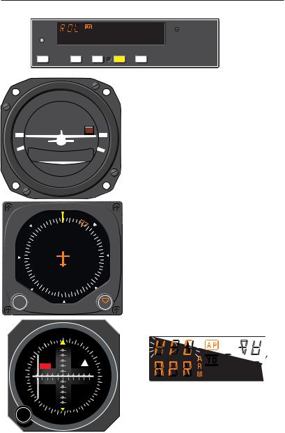
Approach (APR) Mode Using a DG from HDG Mode
(45° Intercept)
The Approach (APR) mode allows the autopilot to intercept and track LOC, VOR/RNAV and GPS courses.
To arm APR mode (with the KAP 140 currently in the HDG mode):
1.Select the desired frequency for LOC, VOR or RNAV. For GPS, verify the desired approach.
2.OBS Knob - SELECT desired approach course. (For a localizer, set it to serve as a memory aid.)
3.APR Mode Selector Button - PRESS. Note APR ARM annunciated.
NOTE: When APR is selected, the autopilot will flash HDG for 5 seconds to remind the pilot to reset the HDG bug to the desired approach course. Check the heading displayed on the DG against the magnetic compass and reset if necessary.
20 |
KAP 140 AUTOPILOT SYSTEM |
Rev. 1 |
Apr/02 |

Single Axis Operation
4. Heading Selector Knob - ROTATE BUG to agree with desired approach course.
Note Instruments: CDI needle to left. Intercept heading 45° to the left of selected (heading bug) course.
5. If the Course Deviation Bar is greater than 2 to 3 dots: the autopilot will annunciate APR ARM; when the computed capture point is reached the ARM annunciator will go out and the selected course will be automatically captured and tracked. If the D-Bar is less than 2 to 3 dots: the HDG mode will disengage upon selecting APR mode; the APR annunciator will illuminate and the capture/ track sequence will automatically begin.
Rev. 1 |
KAP 140 AUTOPILOT SYSTEM |
21 |
Apr/02 |
Single Axis Operation
G
KAP 140
AP |
HDG |
NAV |
APR |
REV |
D.C. ELEC.
TURN COORDINATOR
L  R
R
2 MIN.
NO PITCH
INFORMATION
6 |
E |
3 |
12 |
N |
15 |
|
|
33 |
S |
|
|
30 |
21 |
W |
24 |
PUSH
PU SH
|
E |
12 |
|
|
|
|
|
|
|
|
6 |
|
|
15 |
|
|
N |
|
|
|
|
TO |
|
|
|
|
A |
|
|
3 |
GS |
V |
|
|
|
|
S |
||
|
|
|
||
|
|
|
|
|
N |
|
|
|
21 |
|
|
|
FR |
|
|
|
|
|
|
33 |
24 |
|
|
|
OBS |
30 |
W |
ı
Approach (APR) Mode Using a DG from ROL Mode
(All Angle Intercept)
The Approach (APR) mode allows the autopilot to intercept and track LOC, VOR/RNAV and GPS courses.
To arm APR mode (with the KAP 140 currently in the ROL mode):
1.Maneuver the aircraft to the desired intercept angle prior to selecting ROL mode.
2.Select the desired frequency for LOC, VOR or RNAV. For GPS, verify the desired approach.
3.OBS Knob - SELECT desired approach course. (For a localizer, set it to serve as a memory aid.)
4.APR Mode Selector Button - PRESS. Note APR ARM annunciated.
NOTE: When APR is selected, the autopilot will flash HDG for 5 seconds to remind the pilot to reset the HDG bug to the desired approach course. Check the heading displayed on the DG against the magnetic compass and reset if necessary.
22 |
KAP 140 AUTOPILOT SYSTEM |
Rev. 1 |
Apr/02 |
Loading...