


 Loading...
Skymap IIIC™ & Tracker IIIC™
Pilot Guide & Operating Manual
©Skyforce Avionics Ltd 2006
Skymap IIIC™ & Tracker IIIC™
Pilot Guide & Operating Manual
Manual Revision: SM2105-09 SIIIC Pilot Guide.doc
Unit Software Version 1.22 + (System Model Packages SM4000 & TR4000)
Aeronautical Database: - Supplied courtesy of Jeppesen®
Cartographic Database - AND Products B.V.
Topographic – NOAA (National Oceanographic Atmospheric Administration)
CONTACT ADDRESS |
Honeywell International Inc. |
Skyforce Avionics Limited |
|
5 the Old Granary |
One Technology Center |
Boxgrove, Chichester |
23500 West 105th Street |
West Sussex |
Olathe, Kansas |
PO18 0ES |
USA 66061-1950 USA |
Tel: +44 (0) 1243 783763 |
Tel: 001 913 712 2613 |
Fax: +44 (0) 1243 783992 |
Fax: 001 913 712 1302 |
Email: sales@skyforce.co.uk |
Email: bendixking@honeywell.com |

ELECTRONIC DOCUMENT DETAILS
|
|
NETWORK PATH AND FILE NAME |
|
|
FILE |
|
|
PRINTER |
|
|
|||
|
|
|
|
|
|
|
|
||||||
|
|
|
|
|
|
|
|
TYPE/VERSION |
|
|
|
|
|
|
|
\\Kent\released_dwgs\SM4000\Master Manuals |
|
|
Microsoft® Word |
|
|
Network |
|
||||
|
|
|
|
|
|
|
|
|
|
|
|
|
|
|
HARD DOCUMENT DETAILS |
|
|
|
|
|
|
|
|
|
|||
|
|
|
|
|
|
|
|
|
|||||
|
|
REVISION |
DOI No. |
ORIGINATOR |
DESCRIPTION of CHANGE |
|
DATE |
|
|||||
|
9 |
DOI 159 |
D Allen |
Add |
description of software |
|
19/07/06 |
|
|
||||
|
versions and release document |
|
|
|
|||||||||
|
|
|
|
|
into DOI system |
|
|
|
|
||||
|
|
|
|
|
|
|
|
|
|
|
|
|
|
|
|
|
|
|
|
|
|
|
|
|
|
|
|
DOCUMENT APPROVAL
Authorised for Release for and on Behalf of Skyforce Avionics Limited:
Steve White – Hardware Design Specialist
NOTICES
PROPRIETARY NOTICE
The information disclosed within this document or separately supplied in furtherance of this document includes proprietary rights of Skyforce Avionics Ltd. and Honeywell International Inc. Neither this document nor the information disclosed herein or of a supplementary nature shall be reproduced or transferred to other documents or used or disclosed to others for manufacturing purposes, or for any other purposes, except as specifically authorised in writing by Skyforce Avionics Ltd. or Honeywell International Inc. Skyforce Avionics Ltd. is a subsidiary of Honeywell International Inc. Copyright © 2006 Honeywell International Inc. All rights reserved.
TRADEMARK NOTICE
“Skyforce” and the Skyforce logo are registered trademarks of Honeywell International
Inc., U.S. and UK Patent & Trademark Office’s.
FLIGHT MANUAL
The information contained with this manual is for reference use only. If any information herein conflicts with similar information contained within the Aeroplane Flight Manual
Supplement, the information in the Aeroplane Flight Manual Supplement shall take precedence.
Information in this document is subject to change without notice. Honeywell reserves the right to change or improve its products and to make changes in the content without notification.

TABLE OF CONTENTS
SECTION 1 |
BASIC OPERATION |
1 |
INTRODUCTION |
1 |
|
DEFINITIONS, ACRONYMS AND ABBREVIATIONS |
3 |
|
Definitions |
|
3 |
Acronyms and Abbreviations. |
4 |
|
A QUICK LOOK AT YOUR UNIT |
8 |
|
KEY TO DRAWINGS |
8 |
|
KEY TO DRAWING |
9 |
|
Standard Accessories |
9 |
|
Optional Accessories |
9 |
|
GENERAL INFORMATION |
11 |
|
Soft Keying |
|
11 |
Screen Orientation |
11 |
|
Software Architecture |
11 |
|
Memory Locations |
14 |
|
Screen Icons |
|
14 |
POWER AND ANTENNA CONSIDERATIONS |
16 |
|
Power |
|
16 |
Antenna Considerations (Skymap IIIC only) |
18 |
|
SECTION 2 QUICK REFERENCE GUIDE |
1 |
|
INTRODUCTION |
1 |
|
INITIALISING YOUR UNIT |
1 |
|
SOFTWARE STRUCTURE |
2 |
|
Selecting Demo Mode |
2 |
|
DATABASE SELECTION |
3 |
|
A Quick Word On DIRECT TOs And Flight Plans |
3 |
|
VISUAL DIRECT TO AND DATA INTERROGATION |
4 |
|
DIRECT TO a Specific LatitudeAnd Longitude |
4 |
|
Manual DIRECT TO And Data Interrogation |
5 |
|
USER WAYPOINTS |
5 |
|
Editing/Creating A User Waypoint Manually |
5 |
|
Editing/Creating A User Waypoint Visually |
5 |
|
Saving A User Waypoint In Flight |
6 |
|
FLIGHT PLANS |
7 |
|
Editing/Creating A Flight Plan Manually |
7 |
|
Editing/Creating A Flight Plan Visually |
7 |
|
Selecting A Flight Plan To Fly |
8 |
|
Selecting A Map Mode Navigation Presentation |
9 |
|
Viewing ETAs/Skip Waypoints |
9 |
|
Ten Nearest Search |
9 |
|
Rev 9 Jul 2006 |
i |
Skymap/Tracker IIIC Pilot's Guide |

SETUP MAP FUNCTIONS |
|
10 |
|
SETUP OF NAVIGATION FUNCTIONS |
|
12 |
|
CLEAR MEMORY |
|
13 |
|
SECTION 3 |
DETAILED OPERATION |
|
1 |
TITLE AND HELP SCREENS |
|
1 |
|
Self Test and Initialisation |
|
2 |
|
Main Menu Screen |
|
3 |
|
Note Pad Screen |
|
3 |
|
GPS STATUS SCREENS (SKYMAP IIIC ONLY) |
|
5 |
|
Adjusting Time and Date |
|
7 |
|
Setting Local Time Offset |
|
8 |
|
Setting Present Position |
|
9 |
|
DATA INPUT |
|
|
11 |
FLIGHT PLANNING SCREENS |
|
13 |
|
User Waypoints |
|
13 |
|
Viewing User Waypoints |
|
15 |
|
Manual User Waypoint Editing |
|
16 |
|
Graphical User Waypoint Editing |
|
17 |
|
Editing User Airports |
|
18 |
|
Flight Plans |
|
|
18 |
Manual Flight Plan Building and Editing |
|
19 |
|
Manually Inserting a Waypoint into a Flight Plan and Manual DIRECT TO |
20 |
||
Graphical Viewing and Editing of Flight Plans |
|
23 |
|
Airways Flight Planning |
|
25 |
|
MAP MODE SCREENS |
|
26 |
|
Data Interrogation and Graphical DIRECT TO |
|
27 |
|
Airport Information |
|
28 |
|
Beacon Information |
|
29 |
|
General Icon Information |
|
30 |
|
Airspace Interrogation |
|
30 |
|
NAV MENU SCREENS |
|
32 |
|
Selecting a Flight Plan |
|
34 |
|
Ten Nearest |
|
|
36 |
Airports |
|
|
36 |
Beacons |
|
|
37 |
MAP MODE WITH NAV INFORMATION |
|
39 |
|
Viewing En-route ETA’s and Direct-To Page |
|
40 |
|
Direct To |
|
|
41 |
Arrival at an En-route User Waypoint |
|
42 |
|
Arrival at Your Final Destination |
|
43 |
|
Alternative Navigation Map Modes |
|
44 |
|
TOPO ON / TOPO OFF Large Text Mode |
|
44 |
|
TOPO ON / TOPO OFF CDI (Pseudo CDI) Mode: |
|
44 |
|
DEMO MODE |
|
|
47 |
E6-B CALCULATOR |
|
49 |
|
Rev 9 Jul 2006 |
ii |
Skymap/Tracker IIIC Pilot's Guide |
|

Density Altitude/TAS/Winds Aloft Calculator |
|
49 |
|
Vertical Navigation (VNAV) |
|
50 |
|
Trip/Fuel Planning |
|
52 |
|
Sunset/Sunrise Calculator. |
|
53 |
|
APPENDIX A |
SETUP SCREENS |
|
1 |
SETUP SCREENS |
|
1 |
|
Map Setup Screens |
|
1 |
|
NAV Mode Setup |
|
7 |
|
Personal Identification Number (PIN) Setup |
|
9 |
|
Auto Power-On Lock |
|
11 |
|
Installation and Diagnostic Screens |
|
13 |
|
Screen Position Setup |
|
13 |
|
View Logs |
|
|
14 |
Clear Memory |
|
15 |
|
Data In/Out |
|
|
17 |
APPENDIX B |
WARNING SCREENS |
|
1 |
RAM Lost Warning |
|
1 |
|
Memory Battery Warning |
|
1 |
|
PIN Lock Warning |
|
2 |
|
Lock Out Warning |
|
2 |
|
New Data Card Warning |
|
3 |
|
APPENDIX C |
MEMORY CARDS |
|
1 |
MEMORY CARDS |
|
1 |
|
Data Areas |
|
|
1 |
Changing the memory card |
|
1 |
|
Minimum Safe Altitudes (MSA) |
|
2 |
|
Flight Plan building. |
|
2 |
|
During Flight |
|
2 |
|
Worldwide ICAO Codes. |
|
3 |
|
APPENDIX D HOW DOES GPS WORK? |
|
1 |
|
INTRODUCTION TO GPS |
|
1 |
|
What Is GPS? |
|
1 |
|
How Does It Work? |
|
1 |
|
Accuracy and Reliability |
|
2 |
|
APPENDIX E DIFFERENTIAL FUNCTIONS (SKYMAP IIIC ONLY) |
1 |
||
DIFFERENTIAL GPS |
|
1 |
|
What Is DGPS? |
|
1 |
|
How Does DGPS Work? |
|
1 |
|
Uses Of DGPS |
|
2 |
|
Data Connection |
|
2 |
|
APPENDIX F SERIAL DATA OUTPUT SENTENCES |
|
1 |
|
SERIAL DATA FORMATS |
|
1 |
|
NMEA 0183 Data Format |
|
1 |
|
NMEA – RMC Sentence |
|
1 |
|
NMEA – GGA Sentence. |
|
1 |
|
Rev 9 Jul 2006 |
iii |
Skymap/Tracker IIIC Pilot's Guide |
|

NMEA – RMB Sentence |
1 |
Notes on the RMB sentence |
2 |
RS-232C AR-NAV Data Format |
3 |
Notes on the AR-NAV sentence. |
3 |
APPENDIX G SERVICE AND WARRANTY |
1 |
APPENDIX H PREVIOUS SOFTWARE RELEASES |
1 |
Rev 9 Jul 2006 |
iv |
Skymap/Tracker IIIC Pilot's Guide |

THIS PAGE INTENTIONALLY BLANK
Rev 9 Jul 2006 |
v |
Skymap/Tracker IIIC Pilot's Guide |

BASIC OPERATION
SECTION 1 BASIC OPERATION
INTRODUCTION
All of us at Honeywell congratulate you on choosing this product. You are now the owner of one of the most sophisticated yet simple-to-use navigational aids available today. We understand you probably can't wait to see it in action but before you try to use it do please take the time to read through this Manual and understand its many interesting and useful features. Time spent in familiarising yourself with your new Bendix/King unit will be more than repaid by trouble-free operation later, and more importantly safe and accurate navigation.
We have made the operation of this unit as intuitive as possible through the use of soft keying and on-screen help, thus reducing users' dependence on the Manual. You should very quickly find that handling it efficiently and expertly becomes second nature to you. Don't be afraid to experiment. No matter which Key you activate, your unit will not be damaged. If you do get into a mess, simply switch off and back on again to reset all functions. We must mention just one word of caution. Never remove the memory card whilst the unit is switched on and never attempt to switch the unit on when there is no memory card fitted.
Whichever model of our equipment you have chosen, we at Honeywell are sure you will be pleased with its performance. We thank you for your custom and wish you many happy and safe hours flying.
WARNING
The Global Positioning System (GPS) satellite constellation is operated by the Department of Defence (DoD) of the United States, which is solely responsible for its accuracy and maintenance. Although declared fully operational on July 17th 1995, the system is still under development and subject to changes, which could affect the accuracy and performance of all GPS equipment.
Use this equipment at your own risk. Your new Bendix/King equipment is a precision navigation aid but like any navigational aid it can be misused or misinterpreted and so become unsafe. You are strongly advised to read and fully understand this Manual before using it. Your unit has a DEMO MODE or simulation facility that allows you to practice with it before you begin using it for actual navigation.
Whenever you are using the unit for navigation in the air you should treat it as a supplemental navigation system. You should always carefully compare indications from your Bendix/King equipment with the information available from all other navigation sources including NDB’s, VOR’s, DME's, visual sightings, charts, etc. For safety, any discrepancies observed should be resolved immediately.
The altitude calculated by GPS equipment is geometric height above a theoretical mean sea level of a mathematically calculated ellipsoid that approximates to the shape of the earth.
This altitude can differ significantly from that displayed by your pressure altimeter. You must therefore NEVER USE GPS ALTITUDE FOR VERTICAL NAVIGATION OR TERRAIN
CLEARANCE.
The coloured terrain elevation feature is provided solely as an aid to visual identification of terrain features and must never be used for terrain clearance.
The European Obstacle Data has been generated from each of the countries AIP en-route
Rev 9 Jul 2006 |
1-1 |
Skymap/Tracker IIIC Pilot's Guide |
BASIC OPERATION
OPERATION BASIC
BASIC OPERATION
navigation obstacles section. The respective national authorities do not guarantee that the AIP details are correct or that the list of obstacles is complete.
This equipment is not a replacement for your chart. It is intended as an aid to VFR navigation only. The database within the equipment has been compiled from the latest official information available, and although every care has been taken in the compilation, the manufacturers will not be held responsible for any inaccuracy or omissions therein.
WARNING
Your Bendix/King product is of superior design and craftsmanship and should be treated with care. The suggestions below will help you enjoy the product for many years.
•Keep the Skymap and all its parts and accessories out of the reach of small children.
•Keep the Skymap dry. Precipitation, humidity and liquids containing minerals will corrode the electronic circuits.
•Do not use or store the Skymap in dusty, dirty areas as its components may be damaged.
•Do not store the Skymap in excessively hot areas. High temperatures can shorten the life of electronic devices, damage batteries and warp or melt plastics.
•Do not store the Skymap in excessively cold areas and try to avoid transferring the unit suddenly from a cold to a warm environment. When the unit warms up to its normal temperature, condensation can form inside, which may damage the electronic circuits. If you suspect that there may be internal condensation, allow the unit to warm up slowly and the condensation to clear of its own accord before applying power.
•Do not attempt to open the casing. Only trained and qualified Honeywell technicians can service and repair your unit. Other than the data card the Skymap contains no user-serviceable parts. Non-expert handling may damage the Skymap.
•Do not drop or knock the Skymap. Rough handling may damage the case or internal components.
•Do not use harsh chemicals, cleaning solvents or strong detergents to clean the Skymap. Wipe it with a clean, dry cloth.
•Do not dispose of the Skymap by fire.
Rev 9 Jul 2006 |
1-2 |
Skymap/Tracker IIIC Pilot's Guide |

BASIC OPERATION
DEFINITIONS, ACRONYMS AND ABBREVIATIONS
Definitions
alphabetic: any of the following characters (b/ is a space): b/ABCDEFGHIJKLMNOPQRSTUVWXYZ
alphanumeric: any of the following characters (b/ is a space): b/ABCDEFGHIJKLMNOPQRSTUVWXYZ0123456789
baud: bits per sec
barometric altitude: pressure altitude corrected for barometric altimeter setting
bearing to waypoint: bearing from the present position to the active waypoint measured clockwise relative to true or magnetic north (true is implied unless magnetic is specified)
cross track error: distance from the present position to the nearest point on the desired course, and the direction (right or left) from the desired course to the present position
cursor field: a character position or group of adjacent character positions on which a cursor can appear
data entry field: A data entry field is a data field where the ENTER, SET or SELECT button must be pressed before data entered in the field becomes effective. A data entry field can be a single or multiple character cursor field. During data entry, the active cursor field remains reverse video.
data field: a character position or group of adjacent character positions which display a single data item; a data field may be a single character cursor field, or may contain multiple characters.
data list: an ordered list of data elements which a given cursor field can accept
desired track: The angle, which the desired flight path makes with respect to true north at the point nearest the present position. Magnetic desired track uses the local magnetic variation.
destination: If the active waypoint is not in the active flight plan, the active waypoint is the destination. If the active waypoint is in the active flight plan, the final waypoint in the flight plan is the destination.
distance to waypoint: distance from the present position to the active waypoint
en route safe altitude: the highest minimum safe altitude which will be encountered for a given flight path (present position to destination, via flight plan if appropriate; or a flight path being analysed by trip planning)
ground speed: absolute value of the rate of change of position
headwind: difference between true airspeed and ground speed when true airspeed is
Rev 9 Jul 2006 |
1-3 |
Skymap/Tracker IIIC Pilot's Guide |
BASIC OPERATION

OPERATION BASIC
BASIC OPERATION
more than ground speed
knots: Nautical miles per hour
minimum safe altitude: Minimum safe altitude is the highest minimum off route altitude for any sector within a 10 N.M. square centred at a given position. A minimum off route altitude of 7000 feet or less clears all known obstructions and terrain in a sector by 1000 feet; a minimum off route altitude greater than 7000 feet clears all terrain by 2000 feet. A sector is an area bounded by a 1º latitude/longitude grid.
RAIM: Receiver Autonomous Integrity Monitoring - A technique whereby a GPS receiver determines the integrity of the GPS navigation signals by a consistency check among redundant pseudo range measurements.
scrolling region: a set of consecutive cursor fields which display a portion of a scroll list; "scroll up" means that the data item in each cursor field in the scrolling region moves to the preceding cursor field. The data item in the first cursor field disappears from the page, and the last cursor field displays the next item in the scroll list; "scroll down" is the opposite. If there is other data associated with the data in the cursor fields (such as waypoint numbers in flight plans), it also moves.
selected course: The angle, which the desired flight path makes with respect to true north at the active waypoint. Magnetic selected course uses the magnetic variation at the active waypoint; if the active waypoint is a VOR, the magnetic variation stored for that VOR is used.
special use airspace: any of the following: prohibited area, restricted area, warning area, alert area, MOA, Class CARSA, Class BTCA, unknown, danger, caution, training, CTA, or TMA type
standard rate turn: 3º/sec
tailwind: difference between ground speed and true airspeed when ground speed is more than true airspeed
terminal waypoints: waypoints that are duplicated within a country code or "unnamed" waypoints associated with an approach that are assigned to distinct airports
time to waypoint: distance to waypoint divided by ground speed
track: angle of the aircraft's path over the ground measured clockwise relative to true or magnetic north (true is implied unless magnetic is specified)
Acronyms and Abbreviations.
AC: alternating current
ACT: active (waypoint or flight plan)
ADF: automatic direction finder
ANSI: American National Standards Institute
APT: airport
Rev 9 Jul 2006 |
1-4 |
Skymap/Tracker IIIC Pilot's Guide |

BASIC OPERATION
ARTCC: |
air route traffic control centre |
|
|
ASCII: |
American standard code for information interchange |
||
ATC: |
air traffic control |
|
|
ATF: |
aerodrome traffic frequency |
|
|
ATIS: |
automatic terminal information service |
|
|
A/C: |
aircraft |
|
|
baud: |
or Baud Rate; a measurement of data transmission speed |
||
BRG: |
bearing |
|
|
CAA: |
Civil Aviation Authority |
|
|
CAS: |
calibrated airspeed |
|
|
COM: |
communication |
|
|
CDI: |
course deviation indicator |
|
|
CTA: |
control area |
|
|
CTAF: |
common traffic advisory frequency |
|
|
CTR: |
centre |
|
|
CWI: |
continuous wave interference |
|
|
dB: |
decibels |
|
|
DC: |
direct current |
|
|
DIS: |
distance |
|
|
DME: |
distance measuring equipment |
|
|
DOD: |
United States Department of Defence |
|
|
DOT: |
United States Department of Transportation |
|
|
EFIS: |
electronic flight instrument system |
|
|
ELT: |
emergency locator transmitter |
|
|
ESA: |
en route safe altitude |
|
|
ETE: |
estimated time en route |
|
|
FAA: |
Federal Aviation Administration |
|
|
FAF: |
final approach fix |
|
|
FAR: |
Federal Aviation Regulations |
|
|
FPL: |
flight plan |
|
|
FPM: |
feet per minute |
|
|
FSS: |
flight service station |
|
|
ft: |
feet |
|
|
FT: |
feet |
|
|
G: |
gravitational acceleration = 32.2 ft/sec2 = 9.8 m/sec2 |
||
GAL: |
gallons |
|
|
GPS: |
Global Positioning System |
|
|
hr: |
hour |
|
|
HSI: |
horizontal situation indicator |
|
|
Hz: |
hertz |
|
|
IAF: |
initial approach fix |
|
|
IAP: |
instrument approach procedure |
|
|
IEEE: |
Institute of Electrical and Electronics Engineers |
||
IFR: |
instrument flight rules |
|
|
in.: |
inches |
|
|
INT: |
intersection |
|
|
kHz: |
kilohertz |
|
|
Kt.: |
knots |
|
|
KΩ: |
kilohms |
|
|
LAT: |
latitude |
|
|
Rev 9 Jul 2006 |
1-5 |
Skymap/Tracker IIIC Pilot's Guide |
|
BASIC OPERATION

OPERATION BASIC
BASIC OPERATION
LB: |
pounds |
LED: |
light emitting diode |
LON: |
longitude |
LONG: |
longitude |
LRU: |
line replaceable unit |
m: |
meters |
mA: |
milliamperes |
MATZ: |
Military air traffic zone |
MAHP: |
missed approach holding point |
MAP: |
missed approach point |
mB: |
millibars |
MF: |
mandatory frequency |
MHz: |
megahertz |
mi: |
statute miles |
min: |
minutes |
MOA: |
military operation area |
MSA: |
minimum safe altitude |
msec: |
milliseconds |
NDB: |
non-directional beacon |
N.M.: |
nautical miles |
NPA: |
non-precision approach |
NVM: |
non-volatile memory |
OBI: |
Omni-directional bearing indicator |
OBS: |
Omni-directional bearing selector |
PETE: |
pointer ETE |
RAD: |
radial |
RAM: |
random access memory |
REF: |
reference |
RMI: |
radio magnetic indicator |
RTCA: |
Radio Technical Commission for Aeronautics |
SA: |
Selective Availability (intentional errors introduced by the DoD) |
SAT: |
static air temperature |
sec: |
seconds |
SID: |
Standard Instrument Departure |
SNR: |
signal to noise ratio |
STAR: |
Standard Terminal Arrival Route |
SUP: |
supplemental waypoint |
TAS: |
true airspeed |
TAT: |
total air temperature |
TD: |
time difference |
TMA: |
terminal control area |
TSO: |
technical standard order |
UTC: |
universal co-ordinated time (same as Greenwich Mean Time) |
V:volts
VHF: |
very high frequency |
|
|
VNAV: |
vertical navigation |
|
|
VOR: |
very high frequency Omni-directional radio range |
||
W: |
Watts |
|
|
wpt: |
waypoint |
|
|
Psec: |
microsecond |
|
|
Rev 9 Jul 2006 |
1-6 |
Skymap/Tracker IIIC Pilot's Guide |
|

BASIC OPERATION
PV: |
microvolts |
Ω: |
ohms |
ºC: |
degrees Celsius |
ºF: |
degrees Fahrenheit |
BASIC OPERATION
Rev 9 Jul 2006 |
1-7 |
Skymap/Tracker IIIC Pilot's Guide |

BASIC OPERATION
A QUICK LOOK AT YOUR UNIT
OPERATION BASIC
Skymap IIIC Front View
Skymap IIIC Rear View
KEY TO DRAWINGS
1.Joystick
2.Function Keys
3.ON / OFF / Brightness control
4.Full Colour TFT Liquid Crystal Display.
5.Leg Strap Slot.
6.Accessory Mounting Point.
7.Rear Cover Fasteners.
8.Antenna Socket (Skymap IIIC only)
9.Power/Data Connector.
Rev 9 Oct 2006 |
1-8 |
Skymap/Tracker IIIC Pilot's Guide |

BASIC OPERATION
BASIC OPERATION
Skymap IIIC Rear View - Back Case Removed
KEY TO DRAWING
8.Antenna Socket (Skymap IIIC only)
9.Power/Data Connector.
10.Memory Card.
11.Cooling Air Intake (do not block).
12.Cooling Air Exhaust (do not block).
13.Rear Case Earth Tab (do not bend).
14.Serial number and modification level tag.
Standard Accessories
SM2100 |
Portable Antenna with Cable and Suction Cup (Skymap IIIC only) |
||
SM2104 |
Carrying Case |
|
|
SM2200 |
Leg Strap |
|
|
SM2207 |
Cigar Adapter Cable (Skymap IIIC only) |
||
SM2102 |
Power/Data Cable (Tracker IIIC only) |
|
|
SM2105 |
Pilots Guide |
|
|
SM2106 |
Getting Started Card |
|
|
Optional Accessories |
|
|
|
SM2201 |
Yoke Mount |
|
|
SM2204 |
Panel Mount |
|
|
SM2213 |
Panel Mount with Power/SMB Connector |
||
SM2202 |
Rack Mount |
|
|
SM2209 |
Gimbal Mount |
|
|
SM2228 |
Pedestal Mount |
|
|
SM2203 |
Avionics Interface Module (AIM) |
|
|
KA92 |
Low Profile External Antenna |
|
|
SM2212 |
SMB to BNC Adapter |
|
|
SM2101 |
Antenna Extension Lead |
|
|
SM2225/6/7 |
AC Power Adapter |
|
|
SMP514 |
PC Interface Cable |
|
|
FM25/26/2700 |
Flight Manager PC Software |
|
|
Rev 9 Jul 2006 |
|
1-9 |
Skymap/Tracker IIIC Pilot's Guide |

BASIC OPERATION
OPERATION BASIC
THIS PAGE INTENTIONALLY BLANK
Rev 9 Jul 2006 |
1-10 |
Skymap/Tracker IIIC Pilot's Guide |

BASIC OPERATION
GENERAL INFORMATION
This section of the Manual explains how your Bendix/King unit should be used and provides you with an overview of the software architecture and screen presentation.
This manual provides a detailed explanation of each of the individual screens that your Bendix/King unit displays, and will take you step by step through each of them. To simplify this process each screen is numbered and indexed at the front of this Manual for reference. For those users who wish to get stuck into operating the system immediately, the Quick Reference Section of the Manual has been designed to get you up and running.
The operating system of the Bendix/King Skymap IIIC and Tracker IIIC has been developed from the highly successful Skymap II software. This operating system greatly reduces the number of key presses necessary to activate the various functions, especially those most frequently used in the air. The provision of a joystick makes it considerably simpler to operate the unit and allows you fast and efficient access to most functions.
Soft Keying
You will notice that a label is drawn alongside each valid key. Whenever a new function is selected, by pressing a valid key, a new screen is displayed along with its new key labels. This capability of drawing key labels that are only applicable to a particular screen is referred to as ‘soft keying’, and allows one key to perform multiple functions without the complications of multiple key presses on a conventional keypad.
For the purpose of describing the function of a particular key in this Manual, assume that all the keys on the pictured screen drawings are numbered 1 - 5 from top to bottom. The ensuing text will use this numbering sequence to refer to each specific key. The number shown alongside the pictured screen drawings refers to the number of the screen, which is called when that key is pressed. By using these numbers it is possible to follow the paths through the operating system for all functions. If the word RET is printed next to a key, this means that after the key function is performed the same screen is RETurned. A good example of this is ZOOM IN. All screen drawings show the full Skymap IIIC version of software in Landscape Standard mode. Variations affecting Tracker IIIC are described in the accompanying text.
Screen Orientation
The Skymap IIIC and Tracker IIIC software can be run in one of four display modes and so allows you to mount the unit either horizontally (either Landscape Standard or Inverse) or vertically (either Portrait Standard or Inverse). This enables the user to configure the unit for either left or right handed operation or place the keys along the left, right, top or bottom edges of the case. The default setting on first switch on is Landscape Standard, and it is this mode that is used to illustrate the functions of your unit in this Manual. Refer to Map Setup Screens in the Setup Screens section of this manual if you wish to alter your screen orientation.
Software Architecture
The software in your Bendix/King unit is tree structured, an analogy can therefore be drawn between the trunk of a tree and MAIN MENU. MAIN MENU is the heart of the operating structure and can be accessed by pressing the HELP key after power up or the MAIN MENU key at any other time.
BASIC OPERATION
Rev 9 Jul 2006 |
1-11 |
Skymap/Tracker IIIC Pilot's Guide |
Figure 1 Software Architecture Diagram
BASIC OPERATION
OPERATION BASIC
MAIN MENU has 5 main software branches, which in turn have their own sub software branches. The diagram above depicts the complete tree structure and will serve as a good point of reference whilst you are familiarising yourself with your unit.
GPS |
Shows satellite signal strength, allows UTC, |
STATUS |
local offset, date and position to be set, which |
|
will speed up the initialisation of your unit. |
FLIGHT |
Allows user defined user waypoints and flight |
|
plans to be edited/created. |
EDIT FPLN |
Allows user defined flight plans to be edited |
|
/created either manually or visually. |
USER |
Allows user defined waypoints, airports and |
WPTS |
marker functions to be edited/created either |
|
manually or visually. |
DEMO |
Allows you to practice operating the unit on the |
MODE |
ground using a built-in simulator. |
Rev 9 Jul 2006 |
1-12 |
Skymap/Tracker IIIC Pilot's Guide |

BASIC OPERATION
NOTE PAD |
Allows up to 4000 characters of text, previously |
|
downloaded from a PC using Flight Manager™ |
|
software to be viewed. This Key is only available |
|
if DEMO MODE is not running. DEMO MODE |
|
can only be selected from the first screen after |
|
switching on the unit. |
E6-B CALC |
Allows the E6-B Calculator to be used. |
TAS/WIND |
Allows density altitude, TAS and winds aloft to |
|
be calculated. |
V NAV |
Allows vertical navigation to be Setup. |
TRIP/FUEL |
Allows fuel and trip information to be calculated. |
SUNSET/ |
Allows sunset and sunrise times to be |
RISE |
calculated. |
SETUP |
Allows Setup of map, navigation and |
|
input/output characteristics. |
MAP |
Allows all map functions to be customised, |
SETUP |
including map orientation, airport names, map |
|
units, map datum, display orientation, language, |
|
minimum runway length/surface, extended track, |
|
auto zoom, zoom level map de-clutter facility, |
|
data logging rate and position reporting. |
NAV |
Allows all the NAV functions to be customised, |
SETUP |
including CDI scale, CDI display, CDI alarm, |
|
arrival alarm, auto next leg/leg selection |
|
philosophy, turn anticipation, flight plan display |
|
and alarms. |
PIN SETUP |
Allows the PIN security function to be Setup. |
INST & |
Allows installation and diagnostics for data |
DIAGS |
input/output and GPS receiver (Skymap IIIC |
|
only) to be performed. Flight logs can be viewed |
|
and various sections of memory can be cleared |
|
from here. |
MAP |
This is the primary operating mode of the unit. |
NAV MENU |
Accesses all navigation functions and MSA |
|
information. Joystick toggles NAV Mode. |
FLIGHT |
Allows a flight plan to be selected and edited. |
PLAN |
|
NEAR |
Allows emergency search of 10 nearest airports, |
APTS |
providing information and DIRECT TO capability. |
|
Includes Jeppesen and user defined airports |
|
which satisfies the minimum runway length and |
|
surface requirements. |
BASIC OPERATION
Rev 9 Jul 2006 |
1-13 |
Skymap/Tracker IIIC Pilot's Guide |

OPERATION BASIC
|
BASIC OPERATION |
NEAR |
Allows emergency search of 10 nearest beacons |
NAVAID |
(VOR's and NDB's), providing information and |
|
DIRECT TO capability. |
SAVE WPT Allows your present co-ordinates to be saved in |
|
|
the next available user waypoint number. |
DIRECT TO |
Allows the user to perform a “goto” or DIRECT |
|
TO any point in the internal or user defined |
|
database. It may also be used to obtain |
|
information on any point in the database. |
There are short cuts, which allow you to get to the primary operating mode, MAP mode, more easily; but in general if you wish to get to a specific function in another branch of software, work your way back up the present branch to MAIN MENU by pressing either the SAVE & EXIT, PREV PAGE or MAIN MENU key. Then select the branch of software that contains the desired function you wish to access.
Memory Locations
In the function descriptions, three types of memory, RAM, NVM and Memory Card, are mentioned. You may find it useful to know where various types of information are stored in order to make best use of the equipment. The RAM (Random Access Memory) is built into the unit and is used to store all user-defined data such as User waypoints and Flight plans. The RAM is maintained by battery power from an internal Lithium cell, which should be replaced by your Bendix/King dealer every three years to prevent loss of user-defined data. The NVM (Non Volatile Memory) is also built into the unit. It stores initialisation data, serial number, PIN number and performance log details. This memory is non-volatile which means it is retained even if the memory battery is removed. If you choose to activate the PIN number security feature (similar to that available on many car radios) the non-volatile nature of the NVM ensures your PIN cannot be tampered with or erased. The Memory Card is used to hold the operating system and the database. The memory card can be replaced periodically in order to upgrade the operating system and update the database.
Screen Icons
When showing any map screen - airports, beacons, towns, intersections, user waypoints and many other data classes are represented by symbols or icons, many of which are user selectable in the Map Setup Screens. Please refer to the Setup Screens Section of this Manual for further details.
Rev 9 Jul 2006 |
1-14 |
Skymap/Tracker IIIC Pilot's Guide |

BASIC OPERATION
BASIC OPERATION
Rev 9 Jul 2006 |
1-15 |
Skymap/Tracker IIIC Pilot's Guide |

OPERATION BASIC
BASIC OPERATION
POWER AND ANTENNA CONSIDERATIONS
Power
Your unit is designed to operate from an external source providing a voltage between 10V to 33V DC. An optional AC Power (either 110V or 220/240V) Adapter is also available as an accessory for home use.
A pre-wired connector is supplied with your unit. The tail end of which either has a Cigar Adapter (Skymap IIIC) or flying leads (Tracker IIIC). The cable uses four coloured cores and a braided screen.
The red and blue cores of the cable should be connected to any DC supply between 10 and 33 Volts, capable of supplying 2 Amps.
1.Connect the RED core via a 3 Amp fuse to the positive (+) side of a 10V-33V DC power source.
2.Connect the BLUE core and the braided screen to the negative (-) side of the same power source.
You may also power your unit from a 12 or 24 volt automobile type cigarette lighter socket.
However certain of these lack proper circuit protection and may provide an unreliable supply so we recommend that wherever possible an approved aircraft power source be installed by a licensed radio engineer.
The yellow and green cores are the data in (yellow) and data out (green) lines. If your unit is a Tracker IIIC, the yellow core (data in) should be connected to the data output line of your GPS. Refer to the Data Input Section of this Manual for more details.
If your unit is a Skymap IIIC, the yellow core (data in) can also be connected to the data output line of another GPS, if required and the Skymap IIIC can be switched to Tracker mode and used as a repeater for that GPS.
Your unit also has a differential serial data input and external alarm outputs available on the 9 way connector for optional use. The green core of the cable is connected to the serial data output pin and may be used to drive an AirData computer, a plotter or a data recording device (see SECTION 3 APPENDIX F for details of data output).
Rev 9 Jul 2006 |
1-16 |
Skymap/Tracker IIIC Pilot's Guide |

BASIC OPERATION
BASIC OPERATION
The data presented across the data output pins is controlled by the settings on Screen 35, Data Input/Output Setup and Test Screen. If you want to connect an external audio annunciator to your unit, do so in accordance with the following drawing and activate it’s operation on Screen 23, NAV Mode Customisation Screen by setting EXTERNAL ALARM to ON.
If you are not planning to connect either the green or yellow cores, please cut them back and insulate the cut end. Please do not make connection to pins 3, 6 or 7.
Rev 9 Jul 2006 |
1-17 |
Skymap/Tracker IIIC Pilot's Guide |

OPERATION BASIC
BASIC OPERATION
Antenna Considerations (Skymap IIIC only)
The Skymap IIIC is supplied with a portable antenna that is convenient for use in circumstances where the unit is removed from the aircraft regularly. Your Bendix/King dealer can advise you on other antenna options to suit different applications or improve performance.
When positioning the portable antenna, always ensure that the domed (the opposite side to that which carries the CE marking) face of the antenna is facing straight up to the sky and can “see” a large area of the sky, preferably right down to the horizon. In order to provide a 3-dimensional fix, Skymap IIIC needs to receive signals simultaneously from at least four satellites.
The radio signals from the GPS Navstar satellites are transmitted in an extremely high frequency band (1.5GHz). They can be regarded as having approximately the same penetration capabilities as light. This means that they are able to penetrate only transparent or very thin materials and will be blocked by almost any material that blocks light.
At least four and at times up to twelve GPS satellites should be in view from any place in the world at any time. These can, however, be absolutely anywhere in the sky and so, to ensure uninterrupted navigation it is essential that the antenna has direct line-of-sight contact with as much sky as possible.
If the position in which you wish to locate your Skymap IIIC is shielded from the sky and the standard antenna cable is not long enough for an acceptable installation bearing the above guidelines in mind, you may choose one of several options for remote antenna sitting. The simplest is to use the Bendix/King remote antenna extension cable. This allows the portable antenna to be extended by a further 6ft (2 metres) thereby allowing mounting up to 12ft (4 meters) away from the main unit. The antenna may be held in place there by using the rubber suction cup supplied (which should be slotted into the key hole in the antenna bracket) or fixed permanently in position by using the countersunk screw mounting holes in the antenna bracket. The rubber suction cup is ideal for temporary use in vehicles and light aircraft. The portable antenna is only splash proof and not fully waterproof. Never mount this antenna permanently outside.
For permanent external antenna mounting an external magnetic mount antenna is available for ground vehicles and an external low profile "tear drop" style antenna for aircraft. For more information about these accessories please contact your Bendix/King dealer.
Rev 9 Jul 2006 |
1-18 |
Skymap/Tracker IIIC Pilot's Guide |

BASIC OPERATION
BASIC OPERATION
THIS PAGE INTENTIONALLY BLANK
Rev 9 Jul 2006 |
1-19 |
Skymap/Tracker IIIC Pilot's Guide |
REFERENCE QUICK
QUICK REFERENCE GUIDE
SECTION 2 QUICK REFERENCE GUIDE
This Section of the Manual is designed to provide you with a quick reference guide into the operation of your Bendix/King unit; taking you step by step through the most common functions. If more detail is required, please refer to the appropriate Sections in this Manual. The information contained within this Section is equally applicable to the Tracker IIIC as it is to the Skymap IIIC. Where the Tracker IIIC operation differs, the differences are explained in italic text after each paragraph.
INTRODUCTION
Your Bendix/King unit is operated via a joystick, a series of 5 soft keys, and a rotary ON/OFF switch. The joystick allows movement of the pointer in MAP mode and is used for all forms of data entry or selection.
The appropriate key labels for a particular page are configured in software and drawn alongside the appropriate black key. The rotary ON/OFF switch is used for adjusting the brightness of your screen.
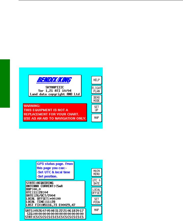
This screen is displayed, giving a warning regarding the expiry date of the Jeppesen® data. This must be acknowledged before you can continue. Please refer to APPENDIX G for details on obtaining data updates.
INITIALISING YOUR UNIT
When an antenna is attached and has a good all round view of the sky, the unit will achieve a position fix within 15 minutes. Ensuring that your GPS has rough UTC, date and position information can significantly speed up this process. To check this switch on the unit, select the HELP key followed by GPS STATUS.
Altering UTC & DATE: Select UTC & DATE, followed by ADJUST UTC. Use the joystick to adjust the time, and then press SET. Now select ADJUST DATE and use the joystick to adjust the date, and then press SET followed by GPS STATUS. Option not available after the
GPS has determined the correct time.
Altering Present Position: Select SET POSN, and use the joystick to adjust the latitude and longitude to your approximate position and then press SET. Alternatively select SET POSN and then VIEW MAP. Move the joystick
on the map to your approximate position (using the ZOOM IN/ZOOM OUT keys where applicable). Once there select SET POSN to change the position. Option not available
Rev 9 Jul 2006 |
2-1 |
Skymap/Tracker IIIC Pilot's Guide |
Loading...