


|
N |
|
KTA970/ |
Pilot’s Guide |
KMH980 |
|
B |
Traffic Alert and Collision Avoidance System/
Multi-Hazard Awareness System
Rev. 3 |
006-18273-0000 |

The information contained in this manual is for reference use only. If any information contained herein conflicts with similar information contained in the Airplane Flight Manual Supplement, the information in the Airplane Flight Manual Supplement shall take precedence.
WARNING
The enclosed technical data is eligible for export under License Designation NLR and is to be used solely by the individual/organization to whom it is addressed. Diversion contrary to U.S. law is prohibited.
COPYRIGHT NOTICE
Copyright ©2001-2003, 2005 Honeywell International Inc. All rights reserved.
Reproduction of this publication or any portion thereof by any means without the express written permission of Honeywell International Inc. is prohibited. For further information contact the Manager, Technical Publications; Honeywell; One Technology Center; 23500 West 105th Street; Olathe, Kansas 66061. Telephone: (913) 712-0400.
Revision History
Manual |
KTA970/KMH980 Pilot’s Guide |
Revision |
3, January 2005 |
Part Number |
006-18273-0000 |
This revision clarifies the determination of when other aircraft are on the ground, and clarifies the GA-EGPWS Self-Test process.
The following pages were changed or added:
Front Cover, Copyright, 14, 55, 56, Back Cover
R-1
Revision History
Manual |
KTA970/KMH980 Pilot’s Guide |
Revision |
2, December 2003 |
Part Number |
006-18273-0000 |
This revision corrects some errors, incorporates additional EGPWS capability and removes references to a specific type of database card.
The following pages were changed or added:
Front Cover, Copyright, ii, 35-37, 41, 46, 50-64, Back Cover
R-2
Revision History
Manual |
KTA970/KMH980 Pilot’s Guide |
Revision |
1, April 2002 |
Part Number |
006-18273-0000 |
This revision incorporates changes from the GA-EGPWS.
R-3
Revision History
Manual |
KTA970/KMH980 Pilot’s Guide |
Revision |
0, September 2001 |
Part Number |
006-18273-0000 |
This is the original version of this publication.
R-4
KTA 970/KMH 980 Pilot’s Guide |
Table of Contents |
TCAS I System Components . . . . . . . . . . . . . . . . . . . . . . . . . . . . . 1
Traffic Displays: . . . . . . . . . . . . . . . . . . . . . . . . . . . . . . . . . . . . . 1 TCAS I Controls: . . . . . . . . . . . . . . . . . . . . . . . . . . . . . . . . . . . . . 1 Optional EGPWS Controls & Displays: . . . . . . . . . . . . . . . . . . . 1
TCAS I Introduction. . . . . . . . . . . . . . . . . . . . . . . . . . . . . . . . . . . . . 2
TCAS . . . . . . . . . . . . . . . . . . . . . . . . . . . . . . . . . . . . . . . . . 3
Section I : Theory of Operation and Symbology . . . . . . . . . . . . 5
TCAS I Operation . . . . . . . . . . . . . . . . . . . . . . . . . . . . . . . . . . . . 6 TCAS I Sensitivity Level . . . . . . . . . . . . . . . . . . . . . . . . . . . 6 TCAS I Surveillance Volumes . . . . . . . . . . . . . . . . . . . . . . . 8
(1) Range Tracking Volumes . . . . . . . . . . . . . . . . . . . . 8
(2) Altitude Tracking Volumes . . . . . . . . . . . . . . . . . . . . 8 TCAS I Aural Inhibits . . . . . . . . . . . . . . . . . . . . . . . . . . . . . . 8
TCAS I Traffic Display Symbols . . . . . . . . . . . . . . . . . . . . . . . . . 8 Non-Threat Traffic . . . . . . . . . . . . . . . . . . . . . . . . . . . . . . . . 9 Proximity Intruder Traffic . . . . . . . . . . . . . . . . . . . . . . . . . . . 9 Traffic Advisory (TA). . . . . . . . . . . . . . . . . . . . . . . . . . . . . . 10 No bearing Traffic . . . . . . . . . . . . . . . . . . . . . . . . . . . . . . . . 10 Off Scale Traffic . . . . . . . . . . . . . . . . . . . . . . . . . . . . . . . . . 11
TCAS I Indications and Voice Announcements . . . . . . . . . . . . 12 TCAS I Traffic Advisory Annunciation (TA): . . . . . . . . . . . . 12
Section II : TCAS I Controls and Displays. . . . . . . . . . . . . . . . . . 15
TCAS I Controls . . . . . . . . . . . . . . . . . . . . . . . . . . . . . . . . . . . . 15 TCAS I Control & Display; KMD 550/850 . . . . . . . . . . . . . . 15 KMD 550/850 Traffic Page (TCAS 1) Operational Controls 16 TCAS I Control Panel; CP 66B. . . . . . . . . . . . . . . . . . . . . . 17 Power Switch: . . . . . . . . . . . . . . . . . . . . . . . . . . . . . . . 18 Range Knob: . . . . . . . . . . . . . . . . . . . . . . . . . . . . . . . . 18 Display Select Switch: . . . . . . . . . . . . . . . . . . . . . . . . . 18 Altitude Limit Switch: . . . . . . . . . . . . . . . . . . . . . . . . . . 18 Weather Radar Indicators . . . . . . . . . . . . . . . . . . . . . . . . . 19
RDS 81, 82, 84 & 86, RDR 2000, RDR 2100 and
Primus /Collins Color Indicators . . . . . . . . . . . . . . . . . 19 Weather Only Mode . . . . . . . . . . . . . . . . . . . . . . . . . . . 20 Weather with TCAS I Traffic Mode. . . . . . . . . . . . . . . . 20 TCAS I Only Mode . . . . . . . . . . . . . . . . . . . . . . . . . . . . 21 Wx & TCAS I Message Formats. . . . . . . . . . . . . . . . . . . . . 21 TCAS I Mode Annunciations . . . . . . . . . . . . . . . . . . . . 21
TCAS I Fault Annunciations . . . . . . . . . . . . . . . . . . . . . 22 TCAS I ONLY mode. . . . . . . . . . . . . . . . . . . . . . . . . . . 22
Section III : TCAS I Operational Procedures. . . . . . . . . . . . . . . . 23
TCAS I Operating Procedures . . . . . . . . . . . . . . . . . . . . . . . . . 24
Before Takeoff . . . . . . . . . . . . . . . . . . . . . . . . . . . . . . . . . . 24 Flight Procedures . . . . . . . . . . . . . . . . . . . . . . . . . . . . . . . 24
After Landing . . . . . . . . . . . . . . . . . . . . . . . . . . . . . . . . . . . 25 Post Flight . . . . . . . . . . . . . . . . . . . . . . . . . . . . . . . . . . 25
Rev 2 |
i |
006-18273-0000 |
KTA 970/KMH 980 Pilot’s Guide |
Table of Contents |
Section IV : TCAS I System Considerations . . . . . . . . . . . . . . . . 27
LIMITATIONS And Notes . . . . . . . . . . . . . . . . . . . . . . . . . . . . . 28
Limitations . . . . . . . . . . . . . . . . . . . . . . . . . . . . . . . . . . . . . 28
Notes . . . . . . . . . . . . . . . . . . . . . . . . . . . . . . . . . . . . . . . . 28
Appendix : TCAS I Self Test . . . . . . . . . . . . . . . . . . . . . . . . . . . . . 29
TCAS I Self Test . . . . . . . . . . . . . . . . . . . . . . . . . . . . . . . . . . . . 30
Failure Conditions. . . . . . . . . . . . . . . . . . . . . . . . . . . . . . . . 31
Radio Altimeter . . . . . . . . . . . . . . . . . . . . . . . . . . . . . . . . . . 31
Glossary of TCAS I Terms . . . . . . . . . . . . . . . . . . . . . . . . . . . . 32
Abbreviations and Definitions . . . . . . . . . . . . . . . . . . . . . . 32
EGPWS (Optional)
EGPWS Introduction . . . . . . . . . . . . . . . . . . . . . . . . . . . . . . . . . . . 35
What is the GA-EGPWS? . . . . . . . . . . . . . . . . . . . . . . . . . . . . . 36 Regulatory Standards . . . . . . . . . . . . . . . . . . . . . . . . . . . . . . . . 37
GA-EGPWS Functions and Features . . . . . . . . . . . . . . . . . . . . . . 39
Aircraft Position. . . . . . . . . . . . . . . . . . . . . . . . . . . . . . . . . . . . . 39 Aircraft Altitude . . . . . . . . . . . . . . . . . . . . . . . . . . . . . . . . . . . . . 40
Terrain, Obstacles & Runway Database. . . . . . . . . . . . . . . . . . 41 Terrain Inhibit Switch. . . . . . . . . . . . . . . . . . . . . . . . . . . . . . . . . 43 Terrain Awareness Display . . . . . . . . . . . . . . . . . . . . . . . . . . . . 44
“Look-Ahead” Alerting and Warning . . . . . . . . . . . . . . . . . . . . . 48 Runway Field Clearance Floor (RFCF). . . . . . . . . . . . . . . . . . . 49 Excessive Rate of Descent Alerting and Warning. . . . . . . . . . . 50 Inadvertent Descent / Loss of Altitude After Take-Off. . . . . . . . 51 GA-EGPWS Altitude Monitoring . . . . . . . . . . . . . . . . . . . . . . . . 52 Altitude Callout . . . . . . . . . . . . . . . . . . . . . . . . . . . . . . . . . . . . . 52 Aircraft Configuration Alerts (Gear & Flap Alerts) . . . . . . . . . . . 53 Bank Angle Alert . . . . . . . . . . . . . . . . . . . . . . . . . . . . . . . . . . . . 53
EGPWS NORMAL PROCEDURES . . . . . . . . . . . . . . . . . . . . . . . . 55
GA-EGPWS System Self-Test . . . . . . . . . . . . . . . . . . . . . . . . . 55
Recommended Procedures for GA-EGPWS Warnings
In Flight . . . . . . . . . . . . . . . . . . . . . . . . . . . . . . . . . . . . . . . . 57 Recommended Procedures for GA-EGPWS Alerts In Flight . . 58
ADDITIONAL EGPWS INFORMATION . . . . . . . . . . . . . . . . . . . . . 59
Audio Message Priority . . . . . . . . . . . . . . . . . . . . . . . . . . . . . . . 59 GA-EGPWS Cockpit Lamps & Switches. . . . . . . . . . . . . . . . . . 61
GA-EGPWS System Limitations . . . . . . . . . . . . . . . . . . . . . . . . 61 GA-EGPWS Continued Airworthiness and Database
Update Procedures . . . . . . . . . . . . . . . . . . . . . . . . . . . . . . . . . 62 GA-EGPWS Product Support . . . . . . . . . . . . . . . . . . . . . . . . . . 63
Rev 2 |
ii |
006-18273-0000 |

KTA 970/KMH 980 Pilot’s Guide |
TCAS I System Components |
SYSTEM COMPONENTS
TRAFFIC DISPLAYS:
KMD 850
Compatible Radar Indicators via GC 362A
Compatible EFIS
TA/VSI
TCAS CONTROLS:
KMD 850
CP 66B TCAS I Controller
Discretes
OPTIONAL EGPWS CONTROLS & DISPLAYS:
KMD 850
Compatible Radar Indicators
Discretes
AUDIO PANEL
Headphone/600 Ohm
TOP ANTENNA |
|
|
|
|
|
|
TRAFFIC DISPLAY/CONTROL |
||
|
Directional |
|
|
KTA 970/ |
|
Option 1 |
|||
|
|
|
KMH 980 |
|
KMD 540 |
||||
|
|
KA 815 |
|
|
|
||||
|
|
|
|
TCAS |
|
Comprised of the following cards: |
|||
|
|
|
|
|
|
||||
|
|
|
|
|
PROCESSOR |
|
KAC 502 (EGPWS) and/or |
||
|
|
|
|
|
|
KAC 504 (Traffic) |
|||
|
|
|
|
|
|
|
|
|
|
CONFIGURATION MODULE |
|
|
|||||||
|
|
KCM 805 |
|
|
|
|
|
|
OR |
|
|
|
|
|
|
||||
|
|
|
|
|
|
|
|
|
|
|
|
|
|
|
|
|
|
|
|
|
|
|
|
|
|
|
|
|
Option 2 |
|
|
|
|
|
|
|
|
|
No Control Unit |
|
|
|
|
|
|
|
|
|
Discrete Control |
|
|
|
|
|
|
|
|
|
PWR SBY TST A/B FL |
|
|
BOTTOM ANTENNA |
|
|
|||||
|
|
|
|
|
|
|
|
|
AIRCRAFT SYSTEMS |
|
|
OR |
|
|
|
|
|
|
• Barometric Altitude - Gilham, ARINC 429 |
|
|
|
|
|
|
|
|
||
|
|
|
|
|
|
|
|
• Heading - XYZ Synchro |
|
|
|
|
|
|
|
|
|
|
|
|
|
|
|
|
|
|
|
|
• Suppression |
Omni-Directional |
Directional |
|
• Discretes |
||||||
(L-Band) |
KA 815 |
|
• Outside Air Temperature |
||||||
|
|
|
|
|
|
|
|
|
|
GPS ANTENNA |
|
|
|
|
|
|
SYSTEM STATUS |
||
|
|
KA 92 |
|
|
|
|
|
|
|
|
|
|
|
|
|
|
|
• TAS VALID |
|
|
|
|
|
|
|
|
|
|
|
|
|
|
|
|
|
|
|
|
• EGPWS INOP |
|
|
|
KTA 970/KMH 980 Block Diagram |
||||||
Rev 2 |
1 |
|
|
006-18273-0000 |
|||||
KTA 970/KMH 980 Pilot’s Guide |
TCAS I Introduction |
INTRODUCTION
TCAS I (an acronym formed from the phrase Traffic Alert and Collision Avoidance System) is an airborne system used for detecting and tracking aircraft near your own aircraft. TCAS I includes a TCAS processor, antennas, a traffic display and a means to control the system. The TCAS processor and antennas detect and track other aircraft by interrogating their transponders. Aircraft detected, tracked, and displayed by TCAS are referred to as Intruders. TCAS analyzes the transponder replies to determine range, relative bearing and relative altitude, if the Intruder is reporting altitude. Should the processor determine that a possible collision hazard exists, it issues visual and aural advisories to the crew. The visual advisory is shown by symbols on the traffic display. Complementing the traffic display, TCAS provides appropriate synthesized voice announcements in the cockpit. A complete list of traffic symbols and announcements is given in the Theory of Operation and Symbology section of this Pilot’s Guide.
TCAS is unable to detect any Intruding aircraft without an operating transponder. TCAS can detect and track aircraft with either an ATCRBS (operating in Mode A or C) or Mode S transponders.
The traffic display shows the Intruding aircraft’s position. TCAS identifies the relative threat of each Intruder by using various symbols and colors. The Intruder’s altitude, relative to your own aircraft’s altitude, is annunciated if the Intruder is reporting altitude. A trend arrow is used to indicate if the Intruder is climbing or descending more than 500 feet per minute. TCAS traffic may be displayed on a weather radar indicator, on a dedicated TCAS display, on a TCAS compatible EFIS Display Unit or a TA/VSI (combination traffic display and vertical speed instrument).
TCAS modes and functions are controlled by switches located on a control panel or in combination with various other controls. A description of controls is given in the Controls and Displays section of this Pilot’s Guide.
ATC procedures and the “see and avoid concept” will continue to be the primary means of ensuring aircraft separation. However, if communication is lost with ATC, TCAS adds a significant backup for collision avoidance.
Rev 2 |
2 |
006-18273-0000 |
KTA 970/KMH 980 Pilot’s Guide |
TCAS I Introduction |
TCAS:
•Is compatible with the ATC System
•Determines if a threat exists from ATCRBS or Mode S Transponder equipped aircraft
•Provides display and audio announcement to the crew
-Position information displayed on a traffic display
-Synthesized voice
•Incorporates sensor inputs and sophisticated algorithms to minimize nuisance visual and aural annunciations.
Rev 2 |
3 |
006-18273-0000 |
KTA 970/KMH 980 Pilot’s Guide |
TCAS I Introduction |
THIS PAGE INTENTIONALLY LEFT BLANK
Rev 2 |
4 |
006-18273-0000 |

KTA 970/KMH 980 Pilot’s Guide |
TCAS I Theory of Operation and Symbology |
SECTION I : THEORY OF OPERATION AND SYMBOLOGY
Section I describes TCAS I Theory of operation and symbology.
Rev 2 |
5 |
006-18273-0000 |

KTA 970/KMH 980 Pilot’s Guide |
TCAS I Theory of Operation and Symbology |
TCAS I OPERATION
TCAS I monitors the airspace surrounding your aircraft by interrogating the transponder of the Intruding aircraft. The interrogation reply enables TCAS I to compute the following information about the Intruder:
1.Range between your aircraft and the Intruder.
2.Relative bearing to the Intruder.
3.Altitude and vertical speed of the Intruder, if the Intruder is reporting altitude.
4.Closing rate between the Intruder and your aircraft.
Using this data TCAS I predicts the time to, and the separation at, the Intruder’s Closest Point of Approach (CPA). Should TCAS I predict that certain safe boundaries may be violated, it will issue a Traffic Advisory (TA) to alert the crew that closing traffic is nearby.
TCAS I SENSITIVITY LEVEL
TCAS I separates the surrounding airspace into two altitude layers. A different sensitivity threshold level for issuing TAs (traffic advisories) is applied to each altitude layer. Lower altitudes have less sensitive TA threshold levels to prevent unnecessary advisories in the higher traffic densities anticipated at lower flight levels, i.e., terminal areas.
TCAS I has two sensitivity levels (SL) which are described in Table 1, TCAS I Sensitivity Levels. SL A is invoked using the following order of precedence: (1) when the TCAS I aircraft is below 2,000 feet AGL (if equipped with radio altimeter) OR (2) when the landing gear is Extended (no radio altimeter installed). SL B occurs under all other flight conditions. Table 2, Typical Traffic Advisory Conditions for Sensitivity Levels describes what conditions will cause a TA to be issued. If aircraft is not equipped with either a radio altimeter or retractable landing gear, TCAS I will stay in SL B at all times.
Sensitivity |
DESCRIPTION |
Level |
SL A In sensitivity level A, TCAS I performs surveillance and tracking functions and provides traffic advisories. The conditions for sensitivity level A are any one of the following:
(1)Own aircraft is in-flight and is below 2,000 feet AGL, if a radio altimeter is installed.
(2)Own aircraft is in-flight and the Landing Gear is extended, if a radio altimeter is NOT installed.
Rev 2 |
6 |
006-18273-0000 |

KTA 970/KMH 980 Pilot’s Guide |
TCAS I Theory of Operation and Symbology |
SL B In sensitivity level B, TCAS I performs surveillance and tracking functions and provides traffic advisories. The conditions for sensitivity level B are based on own aircraft in-flight and:
(1)If radio altitude source is installed and own aircraft altitude is above 2,000 feet AGL (radio altitude).
(2)If radio altitude source is NOT installed and own aircraft has Landing Gear Retracted.
(3)If the aircraft has a fixed landing gear and no radio altimeter is installed.
Table 1: TCAS I Sensitivity Levels
Sensitivity |
CONDITIONS FOR TRAFFIC ADVISORIES (TAs) |
Level |
|
|
|
SL A |
The following conditions cause TCAS I to generate a TA in sensitivi- |
|
ty level A: |
|
• TCAS I calculates that if current closing rate is maintained, sepa- |
|
ration of less than 600 feet in altitude between own and Intruder |
|
will occur in 20 seconds. |
|
• Separation between own and Intruder is less than 600 feet in alti- |
|
tude and less than 0.20 nautical mile range. |
|
• NAR (Non-Altitude Reporting) Intruder is within 15 seconds or |
|
0.20 nautical mile range. |
|
|
SL B |
The following conditions cause TCAS I to generate a TA in sensitivi- |
|
ty level B: |
|
• TCAS I calculates that if current closing rate is maintained, separa- |
|
tion of less than 800 feet in altitude between own and Intruder will |
|
occur in 30 seconds. |
|
• Separation between own and Intruder is less than 800 feet in alti- |
|
tude and less than 0.55 nautical miles in range. |
|
• NAR (Non-Altitude Reporting) Intruder is within 20 seconds or |
|
0.55 nautical mile range. |
|
|
Standby |
|
or Fail |
• TAs are not generated. |
Mode |
|
|
|
Table 2: Typical Traffic Advisory Conditions for Sensitivity Levels
Rev 2 |
7 |
006-18273-0000 |
KTA 970/KMH 980 Pilot’s Guide |
TCAS I Theory of Operation and Symbology |
TCAS I SURVEILLANCE VOLUMES
Surveillance volume is that volume of airspace within which other aircraft with Mode S or ATCRBS transponders are tracked by own aircraft’s TCAS I. The display volume is controlled by the operator and is not necessarily the same as the tracking volume.
(1) Range Tracking Volumes
The size of the range tracking volume is dependent on whether tracking is occurring on a directional or OMNI antenna and attenuation levels applied to the transmitted pulses from the TCAS I processor’s transmitter. The typical range tracking volume is pictured as a circle.
The maximum range for TCAS I is 18 nm. However, there are instances when you may see intruders out to 36 nm. TCAS I reduces range tracking volumes in high density areas to reduce the number of receptions to be processed by TCAS I and for interference limiting. TCAS I can track as many as 45 aircraft and displays up to 30 of them.
(2) Altitude Tracking Volumes
TCAS I tracks other transponder equipped aircraft that are within a relative altitude of +/-10,000 feet.
TCAS I AURAL INHIBITS
TCAS I will inhibit the aural annunciation using the following order of precedence: (1) below 400 ft AGL (if equipped with radio altimeter) OR
(2) when the landing gear is Extended (no radio altimeter installed). For installations aboard aircraft with fixed landing gear and no radio altimeter installed, the aural annunciation is not inhibited by the TCAS I processor, unless weight-on-wheels indicates on the ground. The aural annunciation is enabled above 600 ft AGL in aircraft equipped with a radio altimeter.
TCAS I TRAFFIC DISPLAY SYMBOLS
TCAS I will display three different traffic symbols on the traffic display. The type of symbol selected by TCAS I is based on the Intruder’s location and closing rate. Relative bearing and distance to the Intruder are shown by the position of the Intruder symbol in relation to the own-air- craft symbol.
The symbols change shape and color as separation decreases between your aircraft and Intruders to represent increasing levels of urgency.
The traffic symbols may also have an associated altitude tag that shows relative altitude in hundreds of feet. A + sign and number above the symbol means the Intruder is above your altitude. A - sign and number beneath indicates the Intruder is below your altitude. A trend arrow appears when the Intruder’s vertical rate is 500 feet per minute or greater.
Rev 2 |
8 |
006-18273-0000 |

KTA 970/KMH 980 Pilot’s Guide |
TCAS I Theory of Operation and Symbology |
No altitude number or trend arrow will appear beside any Intruder that is Non-Altitude Reporting (NAR).
If TCAS I direction finding techniques fail to locate the azimuth of another aircraft, a NO BEARING message appears on the screen when the Intruder becomes a Traffic Advisory.
NON-THREAT TRAFFIC
+17 |
An open white diamond indicates that an Intruder’s rela- |
|
tive altitude is greater than ±1200 feet, or its distance is |
||
|
||
|
beyond 5 nm range. It is not yet considered a threat. |
|
|
This traffic is 1700 feet above your own altitude, |
|
|
descending at 500 feet per minute or greater. |
+1700 Ft. and
Descending 

PROXIMITY INTRUDER TRAFFIC
A filled white diamond indicates that the Intruding air- +10 craft is within ±1200 feet and within 5 nm range, but is
still not considered a threat.
This Intruder is now 1000 feet above your aircraft and descending at 500 fpm or greater.
+1000 Ft. and
Descending
Rev 2 |
9 |
006-18273-0000 |

KTA 970/KMH 980 Pilot’s Guide |
TCAS I Theory of Operation and Symbology |
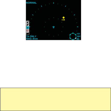
TRAFFIC ADVISORY (TA)
A symbol change to a filled yellow circle indicates that the Intruding aircraft is considered to be potentially hazardous. Depending upon TCAS I sensitivity level, TCAS I will display a TA when time to CPA (Closest Point of Approach) is 15 to 30 seconds.
+05 |
Here the Intruder is 500 feet above your aircraft. A |
|
voice is heard in the cockpit, advising: |
||
|
||
|
“Traffic, Traffic” |
|
|
The crew should attempt to gain visual contact with the |
|
|
Intruder and be prepared to maneuver upon visual |
|
|
acquisition. |
|
|
The crew should take no evasive action |
|
|
based solely on the TCAS I display. |
|
|
+500 Ft. |
NO BEARING TRAFFIC
In installations with dual directional antennas with landing gear down, when omnidirectional antenna is installed on the bottom of the aircraft, or the intruder is located where the TCAS I cannot determine the azimuth of the intruder, a “No Bearing” TA will be annunciated. If traffic can only be seen by the bottom antenna as described above, a “No Bearing” TA would be annunciated as shown. Here the intruder is two nautical miles away and co-altitude (i.e. same altitude).
No Bearing TA
Rev 2 |
10 |
006-18273-0000 |

KTA 970/KMH 980 Pilot’s Guide |
TCAS I Theory of Operation and Symbology |
OFF SCALE TRAFFIC
Threat aircraft (TAs) that are beyond the selected display range are indicated by one half of the traffic symbol at the edge of the screen. The position of the half-symbol represents the bearing of the Intruder.
TA traffic on 5 mile range.
Same TA traffic; beyond selected range.
Rev 2 |
11 |
006-18273-0000 |
KTA 970/KMH 980 Pilot’s Guide |
TCAS I Theory of Operation and Symbology |
TCAS I INDICATIONS AND VOICE ANNOUNCEMENTS
“Traffic, Traffic”
Situation:
One Intruder is ahead near the 2:00 o’clock position, between 2 and 3 miles, 400 feet below your altitude and closing. TCAS I recognizes the threat and issues a TA.
TCAS I TRAFFIC ADVISORY ANNUNCIATION (TA):
Aural |
Visual |
Crew Response |
“TRAFFIC, TRAFFIC” |
A filled yellow circle on the |
Conduct visual search for the |
|
Traffic Display |
Intruder. If successful, maintain |
|
|
visual acquisition to ensure |
|
|
safe operation. |
IMPORTANT:
The pilot should NOT initiate evasive maneuvers using information on the Traffic Display only. Use the TA (Traffic Advisory) symbol to visually acquire the Intruder and be prepared to maneuver upon visual acquisition.
Audio Announcements:
Synthesized voice announcements are issued by TCAS I over the aircraft audio system. The following table lists all the audio messages, and advisories, in the TCAS I vocabulary.
Audio Messages
CONDITION |
ADVISORY MESSAGE |
|
|
Traffic Advisory |
“TRAFFIC, TRAFFIC” |
|
|
If Previous TA is Active |
“TRAFFIC” |
|
|
Self Test Passed |
“TCAS SYSTEM TEST OK” |
|
|
Self Test Failed |
“TCAS SYSTEM TEST FAIL” |
|
|
Rev 2 |
12 |
006-18273-0000 |
KTA 970/KMH 980 Pilot’s Guide |
TCAS I Theory of Operation and Symbology |
Intruders may be seen in surrounding airspace, but not on the TCAS I display. The situations in which this may happen are:
•Most small aircraft have one transponder antenna located on the bottom of the aircraft. When own aircraft is above one of these aircraft, the transponder antenna can be shaded from the TCAS I interrogations. When this occurs, the TCAS I interrogation may not reach the other aircraft’s transponder, or the other aircraft transponder’s reply may not reach TCAS I’s antenna. A lack of replies prevents TCAS I from tracking intruders. Transponder shading also occurs when the other aircraft is maneuvering such that line of sight to its transponder antenna is blocked.
•The TCAS I directional antennas have a bearing “cone of confusion”. TCAS I is able to determine bearings for intruders that are located within –10 degrees to +70 degrees elevation angle with respect to own aircraft’s horizontal plane for the top directional antenna (+10 degrees to –70 degrees for a bottom directional antenna). Intruders that are located outside of those elevation angles will be tracked with no bearing.
•TCAS I is unable to determine bearings for intruder tracked on the bottom antenna when the own aircraft has a bottom monopole antenna or a bottom directional antenna but the landing gear is extended. In this case the intruder will be tracked, but not displayed, unless a Traffic Advisory is issued against it.
•The other aircraft may have a poor transponder. Ground stations have more gain and “hear” aircraft at farther distances than TCAS I.
•TCAS I is required to reduce transmitter power when in areas of high density so that it does not adversely affect (overwork) other aircraft transponders and prevent the ground ATC from tracking them. This is known as Interference Limiting (IL). IL can reduce the nominal TCAS I surveillance range to around 6 nmi. This means that TCAS I may not detect a poorly performing transponder until it is much closer.
•TCAS I has a one-second update rate. When in areas of high density, TCAS I may reduce its maximum surveillance range to either 10 nmi or to the range of the 30th intruder in track plus 1 nmi. This allows TCAS I to maintain its one-second update rate.
•TCAS I has an altitude surveillance volume of –10,000 feet to +10,000 feet relative to own aircraft’s altitude. Any intruders outside this volume are not a threat to own aircraft and therefore are not tracked by TCAS I.
Rev 2 |
13 |
006-18273-0000 |
KTA 970/KMH 980 Pilot’s Guide |
TCAS I Theory of Operation and Symbology |
•The display may not be in the correct viewing mode to show the intruder. The relative altitude modes for the display (KMD 550/850) are:
-Normal mode: -2700 feet to +2700 feet
-Above mode : -2700 feet to +9000 feet
-Below mode: -9000 feet to +2700 feet
Other control head / display combinations may vary on the altitude bands.
•Some displays do not always allow the same range on the sides and aft as out the front. The selected range denotes the range out the front, and the sides and aft will be shown to a lesser range.
•TCAS I does not display other aircraft deemed to be on the ground. When own aircraft is below 1750 feet AGL, any aircraft within 400 feet
of the ground is considered to be on the ground, and therefore not displayed (TCAS I must be connected to a radar altimeter for this feature).
Rev 3 |
14 |
006-18273-0000 |
 Loading...