


Pilot's Guide KTR 909/909A
B
UHF Communications
Transceiver
WARNING
The enclosed technical data is eligible for export under Licanse Designation NLR and is to be used solely by the individual/organization to whom it is addressed. Diversion contrary to U.S. law is prohibited.
COPYRIGHT NOTICE
Copyright ©1995 Honeywell International Inc.
All rights reserved.
Reproduction of this publication or any portion thereof by any means without the express written permission of Honeywell International Inc. is prohibited. For further information contact the Manager, Technical Publications; Honeywell; One Technology Center; 23500 West 105th Street; Olathe, Kansas 66061. Telephone: (913) 712-0400.
UHF TRANSCEIVER
GENERAL INFORMATION
This pilot’s guide contains information about and instructions for operating the KTR 909/909A UHF Comm Transceiver with the KFS 599A UHF Comm Control Head. The KTR 909 must be installed and operated with a KFS 599A UHF Comm Control Head. The KTR 909A can be operated with either a KFS 599A UHF Comm Control Head or a Radio Management System (RMS) using the ARINC 429 interface. This pilot’s guide only covers operation using the KFS 599A UHF Comm Control Head. Refer to the RMS operating procedures on using the KTR 909A in an RMS installation.
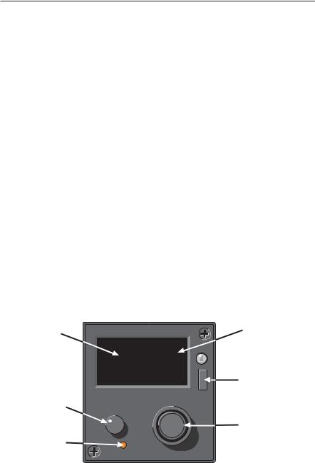
CONTROLS AND DISPLAYS
Controls
This section describes the operational controls of the KFS 599A UHF Comm Control Head. The following controls are described:
•On/Off/Vol/Test Knob
•Channel Select Button
•Frequency/Channel Select Knob
•Push Tone Button
•Mode Select Button
Display |
|
B |
|
|
|
|
|
|
CH20 |
TX |
|
|
MN |
||
|
|
|
GD |
|
39997. O |
||
|
|
|
M |
|
|
|
D |
|
|
|
E |
On/Off/Volume |
|
UHF |
|
|
VOL |
|
|
and Test Knob |
OFF |
|
|
|
PUSH |
PUSH |
|
|
|
TEST |
|
|
|
TONE |
|
Channel Select |
|
|
|
|
|
|
|
Button |
|
CHAN |
|
|
|
|
|
Annunciators
Mode Select Button
Frequency/Channel
Select Knob and
Push Tone Button
1

On/Off/Vol/Test Knob
The On/Off/Vol/Test Knob turns the KFS 599A UHF |
|
|
Comm Control Head on, off, and adjusts volume when |
|
VOL |
rotated. Pressing this knob alternately removes and |
OFF |
PUSH |
applies squelch. |
|
|
|
TEST |
On units without volume control, the audio level is controlled by the aircraft audio/radio control system.
Channel Select Button
The Channel Select button switches the unit between the manual and preset frequency selection modes and also enables the programming
mode. Manual frequency selection (when top display line is blank) |
CHAN |
|
allows direct tuning of the frequency. Preset frequency selection (Channel number displayed in the top line) allows radio tuning using one of the twenty preset channels or the guard frequency. Pressing and holding the CHAN button for more than three seconds activates the Program Mode.
Frequency/Channel Select Knob
• Manual Frequency Mode — Outer knob tunes the trans- |
|
|
ceiver in 1 MHz steps. Inner knob tunes the transceiver in |
PUSH |
|
25 kHz steps. |
||
TONE |
||
• Preset/Guard Channel Mode — Both the outer and the |
|
|
inner knobs change the channel number. |
|
Push Tone Button
Pressing this button activates the 1 kHz tone transmitter test (not |
PUSH |
available while in the BOTH receiver mode). |
TONE |
|
|
Mode Button |
|
Pressing the MODE button selects the Main, Both, or ADF mode of operation. |
M |
The Main mode enables receiving and transmitting on the displayed frequency |
OD |
and is indicated by the MN annunciator. In the Both mode, the receiver scans |
E |
|
the main and guard frequencies. Both the GD and the MN annunciators illuminate during scan. When a signal is detected, the receiver stops on the active frequency and illuminates the active frequency annunciator. Scanning will resume when the receiver becomes inactive. The ADF mode activates an independent ADF receiver.
Displays
This section describes the different display formats of the KFS 599A UHF Comm Control Head. These are:
•Preset Channel/Guard Display
•Manual Tuning Display
•Programming Mode Display
•ADF Mode Display
2
 Loading...