

Page 1
EFS 50
Pilot’s Guide
5-inch Electronic Flight
Instrumentation System
AA
Page 2

Registration
This pilot's guide has been tailored by the installation and or certification agency to cover the following EFS 50 installation:
AIRCRAFT TYPE
AIRCRAFT TAIL OR SERIAL NUMBER
AIRCRAFT OWNER
EFIS TYPE
EFIS SYSTEM CONFIGURATION
EFIS SYSTEM SOFTWARE LEVEL
EFIS DISPLAY UNIT TYPE
EFIS CONTROL PANELS
REVERSIONARY MODES
Throughout this pilot's guide various configuration options are
described. A ✔❏ (check box) precedes each configuration option. A
check mark may be placed in the appropriate boxes to define which
configuration options are available in a given installation.
Page 3

Registration
Page 4

Table of Contents
TABLE OF CONTENTS
Section I
INTRODUCTION I.1
Section 1
SYSTEM CONFIGURATION 1.1
GENERAL 1.1
CONTROL DISPLAY 1.1
CONTROL DISPLAY OPTIONS 1.3
SYMBOL GENERATOR 1.3
EQUIPMENT INTERFACE & OPERATING CONFIGURATION 1.5
SOFTWARE 06 CONFIGURATION PAGES 1.6
SOFTWARE 07 CONFIGURATION PAGES
(includes both 0701 and 0702) 1.10
SOFTWARE 08 CONFIGURATION PAGES 1.14
SOFTWARE 11 CONFIGURATION PAGES 1.18
Section 2
EHSI OPERATION 2.1.1
Detailed Operating Controls 2.1.1
EHSI Controls (CP 467) 2.1.3
HSI 360-DEGREE MODE SELECTION 2.1.3
ARC SECTORED MODE SELECTION 2.1.3
NAV NAVIGATION SENSOR SELECT 2.1.4
1-2 NAVIGATION SYSTEM SELECT 2.1.6
BEARING POINTER SELECT 2.1.6
RANGE SELECTION 2.1.7
TST/REF 2.1.8
TST - 2.1.8
REF GROUND SPEED or TIME-TO-STATION selection 2.1.8
REF MAP FORMAT 2.1.9
COURSE SELECT KNOB 2.1.10
HEADING SELECT KNOB 2.1.10
DISPLAY BRIGHTNESS CONTROL 2.1.10
EADI OPERATION 2.2.1
EADI Detailed Operating Controls 2.2.1
BRIGHTNESS 2.2.1
DH SET 2.2.1
RALT TST 2.2.2
Issued 4/95
SW 06/07/08/11
TOC.1
Page 5

Table of Contents
RADAR OPERATION 2.3.1
Radar Controls, (CP 466A & CP 466B) 2.3.3
OFF-STBY-TST-ON 2.3.4
OFF 2.3.4
STBY 2.3.4
TST 2.3.4
ON 2.3.4
WX 2.3.4
WXA 2.3.4
GND MAP 2.3.4
LIGHTNING 2.3.5
VP 2.3.5
TRK 2.3.6
GAIN 2.3.7
PULL ARL 2.3.7
TILT 2.3.7
MFD OPERATION 2.4.1
Multi Function Display Control Panel 2.4.1
Control Panel Button Operations 2.4.2
TCAS ONLY BUTTON 2.4.2
HSI BUTTON 2.4.2
ARC BUTTON 2.4.2
ENT BUTTON 2.4.2
LNAV MAP 2.4.2
PLAN-VIEW MAP (available with software 07) 2.4.2
CHECKLIST (available with software 08) 2.4.2
NAV BUTTON 2.4.3
RANGE UP/DOWN BUTTONS 2.4.3
CHECKLIST BUTTON 2.4.3
COURSE SELECT KNOB/BUTTON 2.4.3
BEARING #1 & #2 BUTTON 2.4.4
JOYSTICK 2.4.4
LNAV MAP 2.4.4
PLAN-VIEW MAP 2.4.5
CHECKLIST MODE (available with software 08) 2.4.6
1-2 BUTTON 2.4.6
TST/REF BUTTON 2.4.7
Section 3
ABBREVIATED OPERATIONS 3.1
TOC.2
SW 06/07/08/11
Issued 4/95
Page 6

Table of Contents
Section 4
EHSI DISPLAYS 4.1.1
EFS 50 Color Standards 4.1.1
Standard EHSI Displays 4.1.1
NORMAL COMPASS CARD 4.1.1
NAVIGATION SOURCE ANNUNCIATION 4.1.2
SYMBOLIC AIRCRAFT 4.1.3
HEADING SELECT “BUG” 4.1.3
COURSE SELECT 4.1.3
LATERAL COURSE DEVIATION SCALE 4.1.4
LATERAL COURSE DEVIATION BAR 4.1.4
TO/FROM INDICATOR 4.1.5
DISTANCE, GROUNDSPEED and TIME-TO-STATION 4.1.5
DUAL MULTI CHANNEL DME INSTALLATION 4.1.6
DME HOLD 4.1.7
BEARING POINTER 4.1.8
MAGNETIC/TRUE HEADING ANNUNCIATIONS 4.1.10
GLIDE SLOPE/VERTICAL NAVIGATION 4.1.10
WIND VECTOR 4.1.12
DRIFT ANGLE POINTER (LNAV only) 4.1.12
LNAV MODE ANNUNCIATIONS 4.1.12
360 Map Displays 4.1.13
MAP 360 COMPASS CARD 4.1.13
SELECTED COURSE 4.1.13
MAP COURSE DEVIATION INDICATOR 4.1.14
TO/FROM 4.1.14
BEARING POINTER 4.1.14
REFERENCE WAYPOINT 4.1.15
RANGE RING 4.1.16
360-DEGREE MAP WX RADAR (IF EQUIPPED) 4.1.16
TRACK LINE 4.1.17
LIGHTNING DETECTION 4.1.17
FULL TIME LNAV MAP 4.1.18
ARC (Expanded Sectored Mode) Displays 4.1.20
HDG BUG (ALL ARC FORMAT MODES) 4.1.20
COURSE DEVIATION INDICATOR 4.1.20
(EHSI ARC NON-MAP FORMAT)
EADI DISPLAYS 4.2.1
Normal Attitude Display 4.2.1
PITCH ATTITUDE 4.2.1
ROLL ATTITUDE 4.2.1
ROLL INDICATOR 4.2.1
Issued 4/95
SW 06/07/08/11
TOC.3
Page 7

Table of Contents
PERSPECTIVE LINES 4.2.2
SYMBOLIC AIRCRAFT 4.2.2
HEADING TAPE 4.2.2
FLIGHT DIRECTOR COMMAND BARS 4.2.3
AUTOPILOT/FLIGHT DIRECTOR MODE ANNUNCIATION 4.2.3
STANDARD 429 AUTOPILOT/FLIGHT 4.2.3
DIRECTOR MODE ANNUNCIATION
RADIO ALTIMETER 4.2.5
DECISION HEIGHT SET 4.2.6
DECISION HEIGHT ALERT 4.2.6
PRECISION APPROACH MODE FORMAT 4.2.6
EXPANDED LATERAL DEVIATION SCALE 4.2.6
RISING RUNWAY 4.2.7
GLIDESLOPE/VERTICAL NAVIGATION 4.2.8
MARKER BEACON ANNUNCIATION 4.2.8
FAST/SLOW 4.2.8
RATE OF TURN DISPLAY 4.2.9
CATEGORY II ANNUNCIATOR 4.2.9
CATEGORY II OPERATION ANNUNCIATIONS 4.2.9
CATEGORY II THRESHOLDS 4.2.11
ATTITUDE MONITOR 4.2.12
CROSS COMPARATOR ANNUNCIATORS 4.2.12
RA 4.2.12
LOC 4.2.12
GS 4.2.12
ATT 4.2.12
HDG 4.2.13
COMPOSITE DISPLAYS 4.3.1
COMPOSITE MODE 4.3.1
HEADING TAPE 4.3.1
SELECTED COURSE 4.3.1
HEADING BUG SELECT 4.3.1
NAVIGATION SOURCE ANNUNCIATION 4.3.2
LATERAL COURSE DEVIATION SCALE 4.3.2
(Non Approach Mode)
LATERAL COURSE DEVIATION BAR 4.3.2
TO/FROM 4.3.3
DISTANCE INFORMATION 4.3.3
DME HOLD 4.3.3
MFD DISPLAYS 4.4.1
CRS , CRS NOT SELECT 4.4.1
WEATHER ONLY 4.4.1
TRACK LINE 4.4.1
TOC.4
SW 06/07/08/11
Issued 4/95
Page 8

Table of Contents
VERTICAL PROFILE (VP) 4.4.1
SYMBOLIC AIRCRAFT 4.4.1
RANGE RINGS 4.4.1
ALTITUDE LINE 4.4.2
PROFILE ANGLE 4.4.2
PLAN-VIEW, NORTH-UP MAP 4.4.2
TCAS INTERFACE 4.4.3
TCAS ONLY SELECTION 4.4.3
TCAS DISPLAY FORMAT 4.4.4
TCAS TRAFFIC SYMBOLOGY 4.4.4
Intruder Symbols 4.4.4
Vertical Speed Arrow 4.4.4
Data Tag 4.4.4
Off-Scale Traffic 4.4.5
TCAS DISPLAY ANNUNCIATIONS 4.4.5
Traffic 4.4.5
TCAS 4.4.5
TCAS Status 4.4.6
TCAS Mode 4.4.6
Range 4.4.7
Range Rings 4.4.7
Above/Norm/Below 4.4.7
No-Bearing Traffic 4.4.7
FLXXX and FL 4.4.7
Weather/Lightning Annunciation 4.4.8
CHECKLIST INTERFACE 4.4.8
LOADING AND MODIFYING CHECKLIST DATA 4.4.8
NOTICE 4.4.8
CHECKLIST PAGE ORGANIZATION 4.4.9
ROOT INDEX PAGE 4.4.9
SUB INDEX PAGES 4.4.10
CHECKLIST ITEM PAGES 4.4.10
NOTE PAGES 4.4.11
CLEARING CHECKLIST ITEMS 4.4.11
EMERGENCY PAGE ACTIVATION 4.4.11
CHECKLIST CONTROLS 4.4.12
Checklist: CHKLIST 4.4.12
Joystick 4.4.13
Enter : ENT 4.4.13
HSI 4.4.14
ARC 4.4.14
NAV 4.4.14
Up Arrow 4.4.14
Down Arrow 4.4.14
1-2 4.4.15
Issued 4/95
SW 06/07/08/11
TOC.5
Page 9

Table of Contents
RMI 1 4.4.15
RMI 2 4.4.15
CRS(NOT) SEL 4.4.15
TST REF 4.4.15
CRS Knob 4.4.15
Section 5
OPERATING INSTRUCTIONS 5.1
PREFLIGHT PROCEDURES 5.1
START UP 5.1
SELF TEST 5.1
PUSH BUTTON TEST 5.1
PRE-TAKEOFF PROCEDURES 5.1
IN-FLIGHT OPERATION 5.2
ADF 5.2
LNAV (RNAV) 5.2
VNAV 5.3
APPROACH PROCEDURES 5.3
ILS APPROACH 5.3
BACK COURSE APPROACH 5.3
ADF APPROACH 5.4
LNAV (RNAV) APPROACH 5.4
VOR APPROACH 5.4
DECISION HEIGHT SELECTION 5.4
LIMITATIONS 5.5
EMERGENCY PROCEDURES 5.5
Section 6
FAULT ANNUNCIATIONS 6.1
General 6.1
EXTERNAL SYSTEM FAILURES 6.1
HEADING 6.1
ATTITUDE 6.1
FLIGHT DIRECTOR 6.1
EFS 50 SYSTEM FAILURES 6.1
DU—DISPLAY UNIT LOSS OF COOLING 6.1
SG—SYMBOL GENERATOR LOSS OF COOLING 6.1
CP—CONTROL PANEL (CP 467 OR CP 469/A) 6.2
HEADING SELECT “BUG” 6.2
COURSE SELECT 6.2
RCP—RADAR CONTROL PANEL (if equipped) 6.2
SG—SYMBOL GENERATOR 6.3
RAW DATA DEVIATION ANNUNCIATIONS 6.3
TOC.6
SW 06/07/08/11
Issued 4/95
Page 10

Table of Contents
BEARING POINTER ANNUNCIATIONS 6.3
ALPHANUMERIC READOUT ANNUNCIATIONS 6.3
CHECK CONFIG 6.4
WEATHER RADAR ANNUNCIATIONS 6.4
WX FLT 6.4
WX OFF 6.4
BUSY VP 6.4
STB LMT 6.4
429 FLT 6.4
ANT FLT 6.4
TX FLT 6.4
RANGE 6.4
STB OFF 6.5
WAIT 6.5
TCAS FAULT MESSAGES 6.5
FAULT MESSAGES 6.5
Section 7
REVERSIONARY MODES 7.1
CMPST - COMPOSITE 7.2
DISPLAY (EADI) DOWN 7.3
SG 3 7.4
Section 8
GLOSSARY 8.1
Section 9
INDEX 9.1
Issued 4/95
SW 06/07/08/11
TOC.7
Page 11

Table of Contents
*This page intentionally left blank.
TOC.8
SW 06/07/08/11
Issued 4/95
Page 12

INTRODUCTION
Introduction
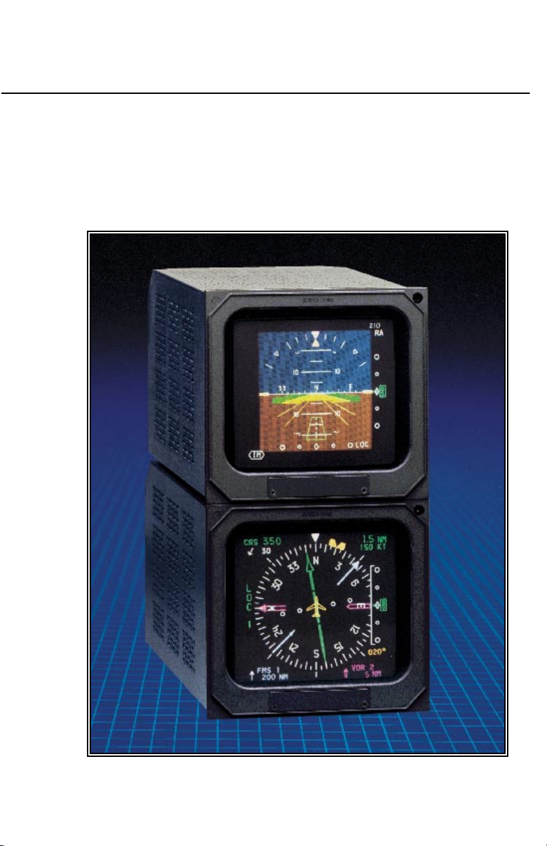
This pilot’s guide describes the
components, operation, and
operational procedures of the
BENDIX/KING EFS 50 Electronic
Flight Instrumentation System
(EFS) containing system
software 0601 and 0701, 0702,
0801, 0802, and 1101. These
software versions will normally be
referred to as 06, 07, 08, and 11
where version 07 includes both
0701 (version 07, mod 1) and
0702 (version 07, mod 2).
Likewise 08 includes both 0801
and 0802.
The EFS 50 system uses a
remote mode controller, CP 467,
and display unit, ED 551/A, for
Equipment covered in this pilot’s guide includes:
ED 551A Display unit, 5” X 5”
SG 465 EFIS symbol generator
CP 467 EFIS control panel with DH set and test
CP 466A RDS 81/82/84 radar control panel
CP 466B RDS 86 radar control panel
CP 469 MFD control panel
CP 469A MFD control panel with checklist and TCAS selection
control and display of navigation
data and sensor selection. The
remote SYMBOL GENERATOR,
SG 465, interfaces with the
navigation sensors to compute
the display and EFIS output data
required by other systems on
board the aircraft.
The CP 469 or CP 469A will
control and select navigation
data for display on the MFD. A
CP 466A or CP 466B provides
the radar control function when
an RDS 81/82/84 or 86 weather
radar is interfaced with the
system, and the associated radar
control/display unit is not
installed.
An Abbreviated Operations
section included in this manual
covers the functions of the EFS
50 in minimal detail. The Abbreviated Operations section gives a
brief visual overview of features
and push button operations.
However, it is necessary to read
the entire Pilot’s Guide for a full
understanding of the EFS 50
system.
SW 06/07/08/11Issued 4/95
Please note: the EFS 50 display
illustrations used in this pilot’s
guide are artist’s reproductions.
Extreme care has been taken to
ensure the accuracy of symbology placement and relative size.
However, it is impossible to
exactly duplicate the display of a
CRT and compensate for all
brightness levels, as line width
displayed on the CRT varies with
I.1
Page 13

Introduction
brightness. In many cases, unrealistic displays provide the most
informative display possible on a
single display. Therefore, we ask
that you use and treat the graphic illustrations contained in this
pilot’s guide as they were intended. These illustrations are to
familiarize the pilot with the type
and placement of data to be provided by the EFS 50.
Note: The data presented in this
pilot’s guide is general in
nature and not tailored toward
a specific installation. Not all
equipment interfaces nor display options presented are
certifiable in all aircraft types
or by all certification agencies.
Each installation may incorporate different equipment complements and use different display options. For the unique
certified operating procedure
of a particular aircraft, refer to
the appropriate approved
Flight Manual Supplement for
that aircraft.
I.2
SW 06/07/08/11 Issued 4/95
Page 14

SYSTEM CONFIGURATION
System Configuration
GENERAL
The 5 tube EFS 50 system Electronic Flight Instrumentation System) offered on the Lear 31A
consists of:
• 2 ea EHSI Display Unit
(ED 551A)
• 2 ea EADI Display Unit
(ED 551A)
• 1 ea MFD (ED 551A)
• 2 ea EFIS Control Panels
(CP 467)
• 1 ea MFD Control Panel
(CP 469 or CP 469A)
• 1 ea RADAR Control Panel
(CP 466A/B)
• 3 ea Symbol Generators
(SG 465)
• 1 ea Switching Unit
(SU 463)
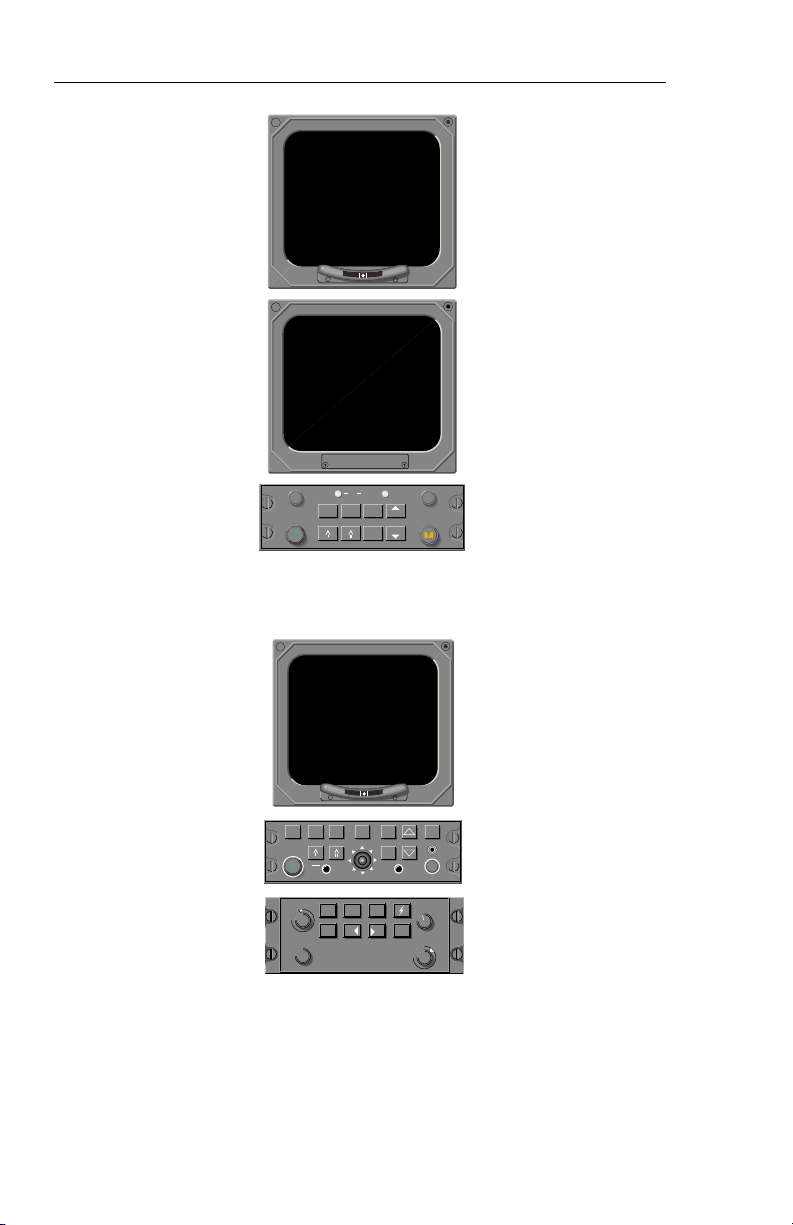
CONTROL DISPLAY
Refer to figure 1.1 for the Control
Display configurations.
The CP 467 Control Panel controls the presentation displayed
on the ED 551A Display Unit
when it is utilized as an EHSI or
EADI. The CP 469/A and CP
466A/B Control Panels control
the ED 551A Display Unit presentation when it is utilized as an
MFD (Multi Function Display).
Figure 1.1 depicts the EFS 50
Control Display Configurations.
Issued 4/95
SW 06/07/08/11
1.1
Page 15
System Configuration
EADI, EHSI CONTROL DISPLAY
2 EA ED 551A & CP 467
ı
1
TST
RALT
SYS
REF
DH
HSI
ARC NAV
ı
BRT
RNG
HDGCRS
RNG
1-2
1.2
TCAS
ARC
HSI
ONLY
CRS
ON
TST
STBY
OFF
ENT
CRS
SEL
WxA
Wx
VP
TK
GAIN
CHK
NAV
LIST
1-2
TST
REF
BRT
GND
BRT
MAP
TK
OFF
UP
TILT O
DN
PULL AUTOPULL ARL
MFD CONTROL DISPLAY
ED 551/A, CP 469/A & CP 466B
Figure 1.1
CONTROL DISPLAY CONFIGURATIONS
SW 06/07/08/11
Issued 4/95
Page 16
System Configuration
CONTROL DISPLAY OPTIONS
The CP 467 and CP 469/A mode
controllers offer a simple means
for the pilot to select the desired
display format, such as standard
compass rose or sectored compass rose, 360-degree map or
sectored map and weather radar
overlay. Also incorporated on
the mode controller is the course
and heading (CP 467) select
knobs with auto sync. The auto
sync feature will slew the head-
SG 465
ing bug to the lubber line or the
course pointer to the DIRECT TO
course for the selected NAV sensor providing a centered D-Bar.
The CP 467 incorporates Decision Height Set and Radio
Altimeter Test.
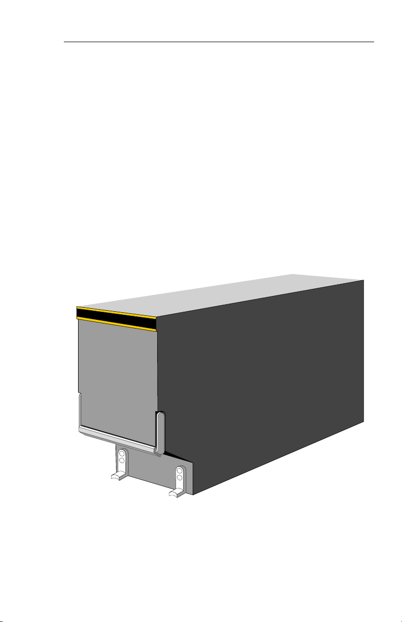
SYMBOL GENERATOR
THE SG 465 EADI/EHSI/MFD
symbol generator is a remotemounted processing unit packaged in an ARINC 3/8 ATR short
form factor.
Issued 4/95
Figure 1.2
SG 465 SYMBOL GENERATOR
SW 06/07/08/11
1.3
Page 17
System Configuration
1
K
12555
LOC GSAP
1257
T
YD
201020
F
10
6
3NT
A
N
10
S
201020
LOC
257
ı
CRS
359
126
N
3
3
3
6
0
3
I
L
E
W
S
1
1
4
2
2
1
1
5
2
S
ADF 2
TST
RALT
SYS
DH
REF
HSI
ARC NAV
RNG
RNG
1-2
S
G
4
6
5
RA
G
S
DH
NM
3.5
G
S
360°
BRT
HDGCRS
ED 551A
ED 551A
CP 467
SG 465
1
340
CRS
23
3
3
V
O
R
1
ARL
WXA
A 2.2
ANT FLT
VOR 1
36.7 NM
ON
Wx
TST
STBY
OFF
GAIN
TCAS
HSI
ONLY
CRS
CRS
NM
36.7
243 KT
N
GND
WxA
MAP
PULL STAB OFF
ARC
ENT
NAV
1-2
TST
SEL
ED 551A
3
9
0
°
40
ADF 2
CP 466
UP
TILT 0
DN
CHK
LIST
CP 469A
REF
BRT
SG 465
S
G
4
6
5
1.4
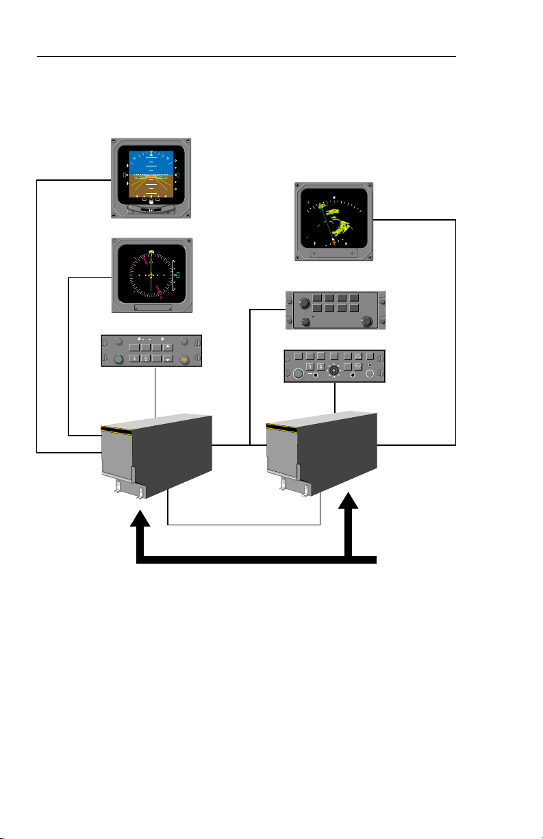
Figure 1.3
TYPICAL EFS 50 SYSTEM BLOCK DIAGRAM
SW 06/07/08/11
REMOTE
EQUIPMENT
{
Issued 4/95
Page 18

EQUIPMENT INTERFACE & OPERATING CONFIGURATION
The following pages are provided
to document the EFS 50 equipment interface and operating
configuration established at the
time of installation and certification. Those pages referring to
software configuration versions
not applicable to this aircraft are
to be removed from this pilot’s
guide.
System Configuration
Issued 4/95
SW 06/07/08/11
1.5
Page 19

System Configuration
SOFTWARE 06 CONFIGURATION PAGES
The EHSI, EADI, MFD and Reversion software will display the following pages. All display information will be identical on the EHSI and
MFD,, however, the EADI will not display the rack configurations, it will
display a comparison of the EHSI and EADI configuration data. The
descriptions given in this section refer to side 1 (left side) as the pilot’s
side and side 2 (right side) as the co-pilot’s side.
——————————|
1 VIEW/EDIT EQUIPMENT PG 01
2 ITEM
3 SG NUMBER _______________
4 SINGLE/DUAL _______________
5 DU TYPE _______________
6 ATTITUDE/HDG #1 _______________
7 ATTITUDE/HDG #2 _______________
8 RATE OF TURN _______________
9 ADF #1 _______________
10 ADF #2 _______________
11 VOR/ILS #1 _______________
12 VOR/ILS #2 _______________
13 ..MORE..
——————————|
1 VIEW/EDIT EQUIPMENT PG 02
2 ITEM
3 DME #1 _______________
4 DME #2 _______________
5 MLS #1 _______________
6 MLS #2 _______________
7 FMS #1 _______________
8 FMS #2 _______________
9 RNAV #1 _______________
10 RNAV #2 _______________
11 TACAN #1 _______________
12 TACAN #2 _______________
13 ..MORE..
1.6
SW 06/07/08/11
Issued 4/95
Page 20

System Configuration
——————————|
1 VIEW/EDIT EQUIPMENT PG 03
2 ITEM
3 VNAV _______________
4 RADAR ALT _______________
5 AFCS TYPE _______________
6 AFCS COMMAND BAR _______________
7 AFCS MODE ANN _______________
8 F/S AIR DATA _______________
9 RADAR TYPE _______________
10 RADAR CTL PNL _______________
11 RADAR INDICATOR _______________
12 CHECKLIST _______________
13 ..MORE..
——————————|
1 VIEW/EDIT EQUIPMENT PG 04
2 ITEM
3 JOYSTICK _______________
4 TCAS _______________
5 HOMING #1 _______________
6 HOMING #2 _______________
7 LIGHTNING DET _______________
Issued 4/95
SW 06/07/08/11
1.7
Page 21

System Configuration
——————————|
1 VIEW/EDIT OPERATING CHAR PG 06
2 ITEM
3 VERT SCALE SIDE _______________
4 DCLTR GS ON BC _______________
5 FULLTIME FMS MAP _______________
6 DISPLAY WIND VEC _______________
7 DISPLAY DRIFT _______________
8 DG ONLY MODE _______________
9 DME DIST ONLY _______________
10 RADAR ONLY MODE _______________
11 HOVER MODE _______________
12 MFD NAV CONTROL _______________
13 ..MORE..
——————————|
1 VIEW/EDIT OPERATING PG 07
2 ITEM
3 DISPLAY HDG TAPE _______________
4 COMMAND BARS _______________
5 ROLL INDICATOR _______________
6 DCLTR UNUS ATT _______________
7 CAT II AVAILABLE _______________
8 PERSPECTIVE LINES _______________
9 DH SELECT _______________
10 CABLE MODE _______________
11 SEL HDG SYNC _______________
12 SEL CRS SYNC _______________
13 ..MORE..
1.8
SW 06/07/08/11
Issued 4/95
Page 22

System Configuration
——————————|
1 VIEW/EDIT OPERATING PG 08
2 ITEM
3 NORTH UP MAP _______________
4 VERT PTR TYPE _______________
5 DISPLAY FMS MSG _______________
6 SEL HDG COLOR _______________
7 CMD BAR COLOR _______________
8 REV MODE ANN _______________
9 RISING RUNWAY _______________
10 ADI DEV SRC _______________
11 CMD BAR FILTER _______________
Issued 4/95
SW 06/07/08/11
1.9
Page 23

System Configuration
SOFTWARE 07 CONFIGURATION PAGES
(includes both 0701 and 0702)
The EHSI, EADI, MFD and Reversion software will display the following pages. All display information will be identical on the EHSI and
MFD, however, the EADI will not display the rack configurations, it will
display a comparison of the EHSI and EADI configuration data. The
descriptions given in this section refer to side 1 (left side) as the pilot’s
side and side 2 (right side) as the co-pilot’s side.
——————————|
1 VIEW/EDIT EQUIPMENT PG 01
2 ITEM
3 SG NUMBER _______________
4 SINGLE/DUAL _______________
5 DU TYPE _______________
6 ATTITUDE/HDG #1 _______________
7 ATTITUDE/HDG #2 _______________
8 RATE OF TURN _______________
9 ADF #1 _______________
10 ADF #2 _______________
11 VOR/ILS #1 _______________
12 VOR/ILS #2 _______________
13 ..MORE..
1.10
SW 06/07/08/11
Issued 4/95
Page 24

System Configuration
——————————|
1 VIEW/EDIT EQUIPMENT PG 02
2 ITEM
3 DME #1 _______________
4 DME #2 _______________
5 MLS #1 _______________
6 MLS #2 _______________
7 FMS #1 _______________
8 FMS #2 _______________
9 RNAV #1 _______________
10 RNAV #2 _______________
11 TACAN #1 _______________
12 TACAN #2 _______________
13 ..MORE..
——————————|
1 VIEW/EDIT EQUIPMENT PG 03
2 ITEM
3 VNAV _______________
4 RADAR ALT _______________
5 AFCS TYPE _______________
6 AFCS COMMAND BAR _______________
7 AFCS MODE ANN _______________
8 F/S AIR DATA _______________
9 RADAR TYPE _______________
10 RADAR CTL PNL _______________
11 RADAR INDICATOR _______________
12 CHECKLIST _______________
13 ..MORE..
Issued 4/95
SW 06/07/08/11
1.11
Page 25

System Configuration
——————————|
1 VIEW/EDIT EQUIPMENT PG 04
2 ITEM
3 JOYSTICK _______________
4 TCAS _______________
5 HOMING #1 _______________
6 HOMING #2 _______________
7 LIGHTNING DET _______________
8 HOVER MODE _______________
9 CABLE MODE _______________
——————————|
1 VIEW/EDIT OPERATING CHAR PG 06
2 ITEM
3 VERT SCALE SIDE _______________
4 DCLTR GS ON BC _______________
5 FULL TIME FMS MAP _______________
6 DISPLAY WIND VEC _______________
7 DISPLAY DRIFT _______________
8 DG ONLY MODE _______________
9 DME DIST ONLY _______________
10 RADAR ONLY MODE _______________
11 SPARE _______________
12 MFD NAV CONTROL _______________
13 ..MORE..
1.12
SW 06/07/08/11
Issued 4/95
Page 26

System Configuration
——————————|
1 VIEW/EDIT OPERATING PG 07
2 ITEM
3 DISPLAY HDG TAPE _______________
4 COMMAND BARS _______________
5 ROLL INDICATOR _______________
6 DCLTR UNUS ATT _______________
7 CAT II AVAILABLE _______________
8 PERSPECTIVE LINES _______________
9 DH SELECT _______________
10 CTL PNL SYNC _______________
11 SEL HDG SYNC _______________
12 SEL CRS SYNC _______________
13 ..MORE..
1 VIEW/EDIT OPERATING PG 08
2 ITEM
3 NORTH UP MAP _______________
4 VERT PTR TYPE _______________
5 DISPLAY FMS MSG _______________
6 SEL HDG COLOR _______________
7 CMD BAR COLOR _______________
8 REV MODE ANN _______________
9 RISING RUNWAY _______________
10 ADI DEV SRC _______________
11 CMD BAR FILTER _______________
Issued 4/95
SW 06/07/08/11
1.13
Page 27

System Configuration
SOFTWARE 08 CONFIGURATION PAGES
The EHSI, EADI, MFD and Reversion software will display the following pages. All display information will be identical on the EHSI and
MFD, however, the EADI will not display the rack configurations, it will
display a comparison of the EHSI and EADI configuration data. The
descriptions given in this section refer to side 1 (left side) as the pilot’s
side and side 2 (right side) as the co-pilot’s side.
——————————|
1 VIEW/EDIT EQUIPMENT PG 01
2 ITEM
3 SG NUMBER _______________
4 SINGLE/DUAL _______________
5 DU TYPE _______________
6 ATTITUDE/HDG #1 _______________
7 ATTITUDE/HDG #2 _______________
8 RATE OF TURN _______________
9 ADF #1 _______________
10 ADF #2 _______________
11 VOR/ILS #1 _______________
12 VOR/ILS #2 _______________
13 ..MORE..
——————————|
1 VIEW/EDIT EQUIPMENT PG 02
2 ITEM
3 DME #1 _______________
4 DME #2 _______________
5 MLS #1 _______________
6 MLS #2 _______________
7 FMS #1 _______________
8 FMS #2 _______________
9 RNAV #1 _______________
10 RNAV #2 _______________
11 TACAN #1 _______________
12 TACAN #2 _______________
13 ..MORE..
1.14
SW 06/07/08/11
Issued 4/95
Page 28

System Configuration
——————————|
1 VIEW/EDIT EQUIPMENT PG 03
2 ITEM
3 VNAV _______________
4 RADAR ALT _______________
5 AFCS TYPE _______________
6 AFCS COMMAND BAR _______________
7 AFCS MODE ANN _______________
8 F/S AIR DATA _______________
9 RADAR TYPE _______________
10 RADAR CTL PNL _______________
11 RADAR INDICATOR _______________
12 CHECKLIST _______________
13 ..MORE..
——————————|
1 VIEW/EDIT EQUIPMENT PG 04
2 ITEM
3 JOYSTICK _______________
4 TCAS _______________
5 HOMING #1 _______________
6 HOMING #2 _______________
7 LIGHTNING DET _______________
8 HOVER MODE _______________
9 CABLE MODE _______________
Issued 4/95
SW 06/07/08/11
1.15
Page 29

System Configuration
——————————|
1 VIEW/EDIT OPERATING CHAR PG 06
2 ITEM
3 VERT SCALE SIDE _______________
4 DCLTR GS ON BC _______________
5 FULL TIME FMS MAP _______________
6 DISPLAY WIND VEC _______________
7 DISPLAY DRIFT _______________
8 DG ONLY MODE _______________
9 DME DIST ONLY _______________
10 RADAR ONLY MODE _______________
11 SPARE _______________
12 MFD NAV CONTROL _______________
13 ..MORE..
——————————|
1 VIEW/EDIT OPERATING PG 07
2 ITEM
3 DISPLAY HDG TAPE _______________
4 COMMAND BARS _______________
5 ROLL INDICATOR _______________
6 DCLTR UNUS ATT _______________
7 CAT II AVAILABLE _______________
8 PERSPECTIVE LINES _______________
9 DH SELECT _______________
10 CTL PNL SYNC _______________
11 SEL HDG SYNC _______________
12 SEL CRS SYNC _______________
13 ..MORE..
1.16
SW 06/07/08/11
Issued 4/95
Page 30

System Configuration
——————————|
1 VIEW/EDIT OPERATING PG 08
2 ITEM
3 NORTH UP MAP _______________
4 VERT PTR TYPE _______________
5 DISPLAY FMS MSG _______________
6 SEL HDG COLOR _______________
7 CMD BAR COLOR _______________
8 REV MODE ANN _______________
9 RISING RUNWAY _______________
10 ADI DEV SRC _______________
11 CMD BAR FILTER _______________
12 MLS VRT ANNUNC _______________
13 ..MORE..
——————————|
1 VIEW/EDIT OPERATING PG 09
2 ITEM
3 DATUM SCALING _______________
4 HDG FAIL ANNUNC _______________
5 VNAV APR SCALE _______________
6 LNAV CRS CTRL _______________
7 SG #1 SIDE _______________
8 AIRCRAFT SYMBOL _______________
9 TACAN ANNUNC _______________
10 TCAS DISPLAYS _______________
11 CAT II SENSORS _______________
Issued 4/95
SW 06/07/08/11
1.17
Page 31

System Configuration
SOFTWARE 11 CONFIGURATION PAGES
The EHSI, EADI, MFD and Reversion software will display the following pages. All display information will be identical on the EHSI and
MFD, however, the EADI will not display the rack configurations, it will
display a comparison of the EHSI and EADI configuration data. The
descriptions given in this section refer to side 1 as the pilot’s side and
side 2 as the co-pilot’s side.
——————————|
1 VIEW/EDIT EQUIPMENT PG 01
2 ITEM
3 SG NUMBER _______________
4 SINGLE/DUAL _______________
5 DU TYPE _______________
6 ATTITUDE/HDG #1 _______________
7 ATTITUDE/HDG #2 _______________
8 RATE OF TURN _______________
9 ADF #1 _______________
10 ADF #2 _______________
11 VOR/ILS #1 _______________
12 VOR/ILS #2 _______________
13 ..MORE..
——————————|
1 VIEW/EDIT EQUIPMENT PG 02
2 ITEM
3 DME #1 _______________
4 DME #2 _______________
5 MLS #1 _______________
6 MLS #2 _______________
7 FMS #1 _______________
8 FMS #2 _______________
9 RNAV #1 _______________
10 RNAV #2 _______________
11 TACAN #1 _______________
12 TACAN #2 _______________
13 ..MORE..
1.18
SW 06/07/08/11
Issued 4/95
Page 32

System Configuration
——————————|
1 VIEW/EDIT EQUIPMENT PG 03
2 ITEM
3 FMS VNAV _______________
4 RADAR ALT _______________
5 AFCS TYPE _______________
6 AFCS COMMAND BAR _______________
7 AFCS MODE ANN _______________
8 F/S AIR DATA _______________
9 RADAR TYPE _______________
10 RADAR CTL PNL _______________
11 RADAR INDICATOR _______________
12 CHECKLIST _______________
13 ..MORE..
——————————|
1 VIEW/EDIT EQUIPMENT PG 04
2 ITEM
3 JOYSTICK _______________
4 TCAS _______________
5 HOMING #1 _______________
6 HOMING #2 _______________
7 LIGHTNING DET _______________
8 HOVER MODE _______________
9 CABLE MODE _______________
10 VARIABLE LNAV _______________
——————————|
1 VIEW/EDIT OPERATING CHAR PG 06
2 ITEM
3 VERT SCALE SIDE _______________
4 DCLTR GS ON BC _______________
5 FULL TIME FMS MAP _______________
6 DISPLAY WIND VEC _______________
7 DISPLAY DRIFT _______________
8 DG ONLY MODE _______________
9 DME DIST ONLY _______________
10 RADAR ONLY MODE _______________
11 SPARE _______________
12 MFD NAV CONTROL _______________
13 ..MORE..
Issued 4/95
SW 06/07/08/11
1.19
Page 33

System Configuration
——————————|
1 VIEW/EDIT OPERATING PG 07
2 ITEM
3 DISPLAY HDG TAPE _______________
4 ADI PLANE/CMD BAR _______________
5 ROLL INDICATOR _______________
6 DCLTR UNUS ATT _______________
7 CAT II AVAILABLE _______________
8 PERSPECTIVE LINES _______________
9 DH SELECT _______________
10 CTL PNL SYNC _______________
11 SEL HDG SYNC _______________
12 SEL CRS SYNC _______________
13 ..MORE..
——————————|
1 VIEW/EDIT OPERATING PG 08
2 ITEM
3 NORTH UP MAP _______________
4 VERT PTR TYPE _______________
5 DISPLAY FMS MSG _______________
6 SEL HDG COLOR _______________
7 CMD BAR COLOR _______________
8 REV MODE ANN _______________
9 RISING RUNWAY _______________
10 ADI DEV SRC _______________
11 CMD BAR FILTER _______________
12 MLS VRT ANNUNC _______________
13 ..MORE..
——————————|
1 VIEW/EDIT OPERATING PG 09
2 ITEM
3 DATUM SCALING _______________
4 HDG FAIL ANNUNC _______________
5 VNAV APR SCALE _______________
6 LNAV CRS CTRL _______________
7 SG #1 SIDE _______________
8 AIRCRAFT SYMBOL _______________
9 TACAN ANNUNC _______________
10 TCAS DISPLAYS _______________
11 CAT II SENSORS _______________
10 RADAR SCAN _______________
1.20
SW 06/07/08/11
Issued 4/95
Page 34

System Configuration
——————————|
1 VIEW/EDIT OPERATING PG 10
2 ITEM
3 RADAR SDI _______________
4 PITCH SYNC DISC _______________
Issued 4/95
SW 06/07/08/11
1.21
Page 35

System Configuration
* This page intentionally left blank.
1.22
SW 06/07/08/11
Issued 4/95
Page 36

EHSI OPERATION
DETAILED OPERATING CONTROLS
EHSI Operation
All possible EFS 50 Interfacing
Equipment is described in the
Detailed Operating Controls section of the EFS 50 Pilot’s Guide,
however, all may not be active in
a specific installation.
This section, EHSI Operation, will
describe the operation of both
the CP 468 EHSI control panel
340
CRS
23
33
V
O
R
1
ARL
WXA
A 2.2
ANT FLT
VOR 1
36.7 NM
and the EHSI section of the
CP 467 EHSI/EADI control panel.
The EADI operation of the
CP 467 is covered in section 2.2,
EADI Operation. The CP 466A/B
radar control panels are covered
in section 2.3, RADAR Operation. The CP 469/A MFD Control
Panel is covered in section 2.4,
MFD Operation.
1
NM
36.7
243 KT
3
90°
40
ADF 2
0:09
N
Issued 4/95
TST
RALT
DH
HSI
ARC NAV
1-2
SYS
REF
RNG
RNG
Figure 2.1
ED 551A Display Unit and
Companion/CP 467 Control Panel
SW 06/07/08/11
BRT
HDGCRS
2.1.1
Page 37

EHSI Operation
360 MODE SELECT
HSI COMPASS ROSE
NAV MAP
NAV MAP WITH WX
DG
PULL SET
RADIO ALTIMETER
DH
#1 BEARING
POINTER SELECT
DECLUTTER
VOR, TCN OR RNV
TCN
FMS, LOR, OMG, or GPS
NAV
MLS
ADF
DME DISTANCE ONLY
SECTORED MODE SELECT
ARC COMPASS ROSE
ARC NAV MAP
ARC NAV MAP WITH WX
ARC COMPASS ROSE WITH WX
PUSH TEST
RADIO ALTIMETER
RALT
HSI
#2 BEARING
POINTER SELECT
DECLUTTER
VOR, TCN OR RNV
TCN
FMS, LOR, OMG, or GPS
NAV
MLS
ADF
DME DISTANCE ONLY
TST
ARC NAV
SYS
1-2
NAV SOURCE SELECT
VOR, LOC,TCN or RNV
TCN
FMS, LOR, OMG or GPS
NAV
MLS
ADF
HOM
REF
RNG
RNG
TEST/REF
TEST
*GROUND SPEED
*TIME-TO-STATION
NAV MAP FORMAT
BRT
HDGCRS
RANGE SELECT
NAV MAP
WX
SYSTEM 1-2 SELECT
*NO SELECTION
AFTER SW 08
Figure 2.2
CP 467 Control Panel
For clarification on a particular
display or operational feature,
refer to section IV. EHSI DISPLAYS or section V. OPERATING INSTRUCTIONS. Figure
2.1 shows the CP 467 stand-
2.1.2
SW 06/07/08/11
alone EHSI/EADI Mode Controller & companion ED 551/A
Display unit and figure 2.2 shows
the CP 467 Mode Controller
Operation.
Issued 4/95
Page 38

EHSI CONTROLS (CP 467)
EHSI Operation
HSI 360-DEGREE MODE SELECTION
HSI
The EFS 50 has four possible
360-degree display formats:
standard HSI compass rose,
NAV map, NAV map with weather, and DG mode. Each press of
the HSI button sequentially
selects the next display format.
A press of the HSI button while in
the ARC mode will change the
display to the standard HSI compass rose.
The display selection list may
include the following:
HSI COMPASS ROSE
HSI NAV MAP
HSI NAV MAP
H
WITH WEATHER
(OPTIONAL)
S
I
DG MODE
(OPTIONAL)
PLAN VIEW
(OPTIONAL ON MFD)
DG ONLY and WEATHER are
options selected at the time of
installation and are included in
the system certification.
If a compatible weather radar is
not installed, the weather option
will not be in the sequence.
ARC SECTORED MODE SELECTION
ARC
The ARC mode provides the pilot
a large scale view of the CDI by
presenting an approximate 85degree sector display of the compass.
The EFS 50 has five possible
ARC sectored display formats:
standard HSI compass rose,
NAV CDI map, NAV CDI map
with weather and standard HSI
compass rose with weather. A
software configuration option,
selectable at the time of installation and certification, allows a
weather only mode to be selected on the MFD. A press of the
ARC button will sequentially
select the possible display formats.
A press of the ARC button while
in the 360-degree mode will
result in an ARC presentation of
the same format. For example, if
the 360 NAV MAP WITH
WEATHER mode is being dis-
Issued 4/95
SW 06/07/08/11
2.1.3
Page 39

EHSI Operation
played and the ARC button is
pressed, the resulting display format will be ARC NAV MAP WITH
WEATHER.
ARC COMPASS ROSE
ARC NAV MAP
A
R
C
WEATHER is an option selected
at the time of installation and is
included in the system certification. If a compatible weather
radar is not installed, the weather
option will not be in the
sequence.
An additional ARC format option
is offered, selectable at the time
of installation and certification,
which provides an uncluttered
weather radar presentation on
the MFD. The MFD ARC weather only format provides a typical
weather radar presentation, no
navigation data is presented
when this mode is selected.
ARC NAV MAP WITH WEATHER (OPTIONAL)
ARC COMPASS ROSE WITH WEATHER (OPTIONAL)
ARC WEATHER ONLY (OPTIONAL ON MFD)
The ARC display selection list
may include the following:
NAV NAVIGATION SENSOR SELECT
NAV
During installation, the EFS 50
symbol generator was programmed with the type and
quantity of each piece of interfacing equipment. Not all the
equipment interfaced to the
EFS 50 is usable for primary navigation. The EFS 50 creates and
maintains in permanent memory
a list of the interfacing navigation
sensors.
Refer to radar controls in this
section for details on weather
radar operation.
2.1.4
SW 06/07/08/11
The NAV push button is used to
select which NAV sensor provides primary navigation data. A
Issued 4/95
Page 40

EHSI Operation
press of the NAV sensor select
button sequentially selects the
next available sensor from the list
of those installed. Primary Navigation Data is defined as the distance in the upper right corner,
selected course, course pointer
and deviation.
The Primary Navigation Sensor
is annunciated at the side of the
ON-SIDE EFS CROSS-SIDE EFS
VOR (VOR, LOC, TCN or RNV)
NAV
TCN (Control head)
NAV
LNAV, (FMS, LOR OMG or GPS)
N
A
V
NAV
MLS
display unit opposite the vertical
scale. Only those sensors interfaced to the EFS 50 in a specific
installation will be selectable for
use and display.
The following is an all-inclusive
list, in order, of primary navigation sensors that may be interface with the EFS 50:
1-2
NAV
1-2
NAV
1-2
NAV
1-2
VOR (VOR, LOC, TCN or RNV)
TCN (Control head)
LNAV, (FMS, LOR, OMG, or GPS)
MLS
NAV
ADF
NAV
HOM
NAV
NAV
1-2
NAV
1-2
ADF
HOM
NOTES: If a number 2 NAV sensor has been selected for display
on the number 1 EHSI by pressing the 1-2 button and the number
Issued 4/95
SW 06/07/08/11
2.1.5
Page 41

EHSI Operation
1 EHSI NAV push button is
pressed, the next available
number 1 NAV sensor will be
selected.
ADF D-Bar presentation may
not be available if the ADF
does not provide a suitable
flag output.
Software 08 treats unlike LNAV
sources (i.e. FMS, LOR, OMG, or
GPS) as single sensors. When
two unlike LNAV sources are
configured, the EFS will display
both the on-side LNAV and the
off-side LNAV without a system
number and the NAV button is
used to select between them.
1-2 NAVIGATION SYSTEM SELECT
1-2
The 1-2 button is used to cycle
between primary navigation sensor system #1 and #2 for display.
The primary NAV system selected is annunciated as sensor 1 or
sensor 2 on the EHSI. Example,
if VOR 1 is being displayed and
the 1-2 button is pressed, VOR 2
will become the displayed sensor. If only one sensor is
installed, the display will not cycle
and the sensor annunciation will
not show a system number. For
example ADF would be displayed
(not ADF 1) in installations containing a single ADF.
Note: The cross-side sensor for
VOR could be TCN, for LNAVs
it could be a combination of
FMS, OMG , LOR, or GPS.
After software 08, the 1-2 button no longer selects between
unlike LNAV sources.
When a RMI or NAV sensor
select button is pressed and it
is not active in the system, a
yellow “FUNCTION NOT
IMPLEMENTED” will be displayed in the center of the
screen.
BEARING POINTER SELECT
The bearing pointer select buttons work in a similar manner as
the NAV sensor select button. A
press of the bearing pointer button sequentially selects the next
available sensor for display. The
bearing pointer sensor list contains only those sensors which
have bearing information capabilities. If the selected sensor has
distance information paired with
it, that distance will also be displayed below the sensor annunciation. An optional push button
sequence allows independent
selection and display of the
respective DME distance without
the presence of the bearing
pointer.
2.1.6
SW 06/07/08/11
Issued 4/95
Page 42

EHSI Operation
The following is an all-inclusive list, in order, of the bearing pointer
sensors that may be interfaced with the EFS 50:
DECLUTTER, (NO #1 OR #2 BEARING POINTER INFORMATION IS DISPLAYED)
VOR, (VOR OR TCN)
TCN, (ONLY AVAILABLE WHEN THE TACAN HAS AN INDEPENDENT CONTROL HEAD)
OR
LNAV, (FMS, LOR, OMG, OR GPS)
MLS
ADF
DME DISTANCE ONLY, (OPTIONAL)
Only those sensors interfaced to
the EFS 50 will be included in the
sequence.
Software 07 added an option
selectable at the time of installation and certification that
removes the ability to display a
MLS bearing pointer.
For a single ADF installation,
the ADF bearing pointer may
be displayed on either the single or double bar pointer. The
annunciation associated with
either bearing pointer will be
ADF, not ADF 1 or ADF 2.
Note: Any single bearing
pointer sensor may be displayed on either pointer. This
includes unlike LNAV sources
after software 08.
RANGE SELECTION
RNG
RNG
A press of the RANGE DOWN
button selects the next lower
range to be displayed while in the
NAV MAP or WEATHER modes
of operation. Once the lowest
selectable range is reached, the
RANGE UP button must be used
for a range change.
The operation of the RANGE UP
button is similar to the RANGE
DOWN except it selects the next
higher range to be displayed
while in the NAV MAP or
WEATHER modes of operation.
Note: To display weather infor-
mation on the copilot’s EHSI it
selected range must match
one of those ranges displayed
on the MFD or pilot’s EHSI.
Issued 4/95
SW 06/07/08/11
2.1.7
Page 43

EHSI Operation
When the map range on the
MFD or pilot’s EHSI no longer
matches the range selected on
the copilot’s EHSI the copilot
will display stale weather information for 30 seconds. A “WX
FLT” warning will then display
on the RADAR fault warning
line alerting the pilot of range
mismatch.
TST/REF
SYS REF
The TST/REF button performs
three functions: SELF TEST display, Ground speed or Time-toStation selection and LNAV MAP
formatting.
◗ TST -
To display the EHSI system
SELF TEST, press and hold the
TST/REF button for three seconds. Upon entering Self Test, a
test pattern will be displayed. In
the center of the test pattern,
either a SELF TEST PASS or
SELF TEST FAIL will be annunciated. With 06 software, the
SELF TEST display will remain
until the TST/REF button is
pressed again. Beginning with
07 software, the EFIS will cancel
the test mode and return both the
EADI and EHSI to normal operation after 5 seconds.
Note: If the SELF TEST FAIL
message is annunciated, the
system should be serviced.
◗ REF GROUND SPEED or
TIME-TO-STATION selection
With software 06 and 07, the
TST/REF button allows alternate
selection of Ground speed or
Time-to-station (in minutes) as
calculated by the selected primary NAV system. When Ground
speed or Time-to-station information is available it will be displayed below the distance information in the upper right corner
of the display. If the information
is not provided, the associated
annunciator will be removed.
The alternate selection of Ground
speed and Time-to-station will
not be allowed in the MAP mode
with an LNAV selected as the primary navigation source.
After software 08, both ground
speed and Time-to-station are
displayed simultaneously. Timeto-station is displayed immediately below the Ground speed using
the format of hours and minutes
seperated by a colon (H:MM).
Note: The Time-to-station field
used with software 08 can also
be used for an abnormal DME
annunciation which has priority.
The EFS 50 will calculate ground
speed and Time-to-station in
installations which use an ARINC
568 type DME. If a conventional
DME indicator is also used, differences in ground speed and
Time-to-station display may be
notices.
2.1.8
SW 06/07/08/11
Issued 4/95
Page 44

EHSI Operation
Note: Time-to-station is replaced
with Time-to-waypoint when the
selected primary nav is an LNAV
providing this information.
◗ REF MAP FORMAT
When the selected EFS 50 display is LNAV MAP, the TST/REF
button allows selection of the
desired NAV MAP format. To
determine the present MAP format momentarily press the
TST/REF button. The momentary button press will activate the
present MAP format annunciation. If the displayed format is
desired, no additional action is
required; the format message will
be removed within 5 seconds. If
a different format is desired,
FPL ID
(FLIGHT PLAN WITH
FULL ICAO IDENTIFIERS)
TEST
AIRPORT
(TO WAYPOINT AND NEAREST
AIRPORTS WITH ICAO IDENTIFIERS)
REF
sequence through the list by
momentarily pressing the
TST/REF button until the desired
format is displayed. Approximately 5 seconds after the last
button press, the map format
annunciation will be removed.
With software 06 and 07, the
NAV map format will remain as
previously selected until changed
using the TST/REF button, however beginning with 08 software
the NAV map format is re-set to
FPL ID each time a MAP display
is activated.
The following is an all-inclusive
list, in order, of the possible NAV
MAP formats:
NAVAIDS
(TO WAYPOINT AND NEAREST NAVAIDS
WITH ICAO IDENTIFIERS)
Note: Depending upon the Flight Management System installed,
the above format options may not be fully supported. Systems
such as the BENDIX/KING KNS 660 and KLN 88, that support the
GAMA 429 LNAV data bus will provide the above format options.
Issued 4/95
SW 06/07/08/11
2.1.9
Page 45

EHSI Operation
COURSE SELECT KNOB
CRS
Rotation of the COURSE
SELECT knob allows the course
pointer and digital course to be
set at the desired course.
The CP 467 and CP 468 provide
a ”DIRECT TO” feature. Pulling
the CP 467 or CP 468 COURSE
SELECT knob will cause the
course pointer and digital course
read out on the EHSI to slew to
the direct course to the selected
NAVAID.
If the selected NAV sensor is an
LNAV system, it may have
modes of operation that control
the selected course.
During these LNAV modes of
operation the EFS 50 COURSE
SELECT knob will be inactive.
The CP 467 and CP 468 provide
a “HEADING SYNC” feature.
Pulling the CP 467 or CP 468
HEADING SELECT knob will
cause the heading bug on the
EHSI to slew to the present aircraft heading (lubber line).
DISPLAY BRIGHTNESS CONTROL
BRT
The BRT knob controls the display brightness.
Note: The display brightness
control provides full range dimming to allow night operation
in no- or low-light situations.
The lower limit of the display
brightness may appear as an
inoperative tube during normal
daylight operation. It is therefore advisable to check the
BRT knob setting during preflight test.
HEADING SELECT KNOB
HDG
Rotation of the HEADING
SELECT knob allows the heading bug on the EHSI to be rotated
to the desired heading.
2.1.10
SW 06/07/08/11
To ensure maximum display
tube life, it is highly recommended that the display be
operated at the lowest acceptable brightness level.
Issued 4/95
Page 46

EADI OPERATION
EADI DETAILED OPERATING CONTROLS
EADI Operation
This section, EADI Operation, of
the EHI 50 Pilot’s Guide
describes the EADI operational
controls of the CP 467 used with
an ED 551/A EADI.
EADI controls are limited to three
basic functions: EADI display
brightness adjustment, DH (deci-
TST
ARC NAV
DH
RALT
HSI
Figure 2.2.1
CP 467 EFIS CONTROL PANEL
BRIGHTNESS
BRT
The BRT knob controls the display brightness.
Note: The display brightness
control provides full range dimming to allow night operation
in no- or low-light situations.
The lower limit of the display
brightness may appear as an
inoperative tube during normal
daylight operation. It is therefore advisable to check the
sion height) set and Radio Altitude test.
For clarification on a particular
display or operational feature
refer to section IV, EADI DISPLAYS or section V, OPERATING INSTRUCTIONS.
SYS
REF
BRT
HDGCRS
1-2
RNG
RNG
BRT knob setting during preflight test.
To ensure maximum display
tube life, it is highly recommended that the display be
operated at the lowest acceptable brightness level.
DH SET
DH
To set the Decision Height, pull
out and turn the DH knob. Turning clockwise will increase the
Issued 4/95
SW 06/07/08/11
2.2.1
Page 47

EADI Operation
Decision Height selected, turning
counter clockwise will decrease
the Decision Height. The DH set
knob is variable rate, the faster
the knob is turned, the greater
the change in a given amount of
rotation. The Decision Height
range is from “OFF” to 2,500 feet
and will be displayed in one foot
increments up to 500 feet and
then in 10 foot increments to
2,500 feet.
Once the desired DH is selected,
push in the DH set knob to lock
the selected DH altitude. If DH is
set to OFF, the “DH” annunciation will not be displayed.
RALT TST
RALT
Pressing the RALT TST (Radio
Altimeter Test) push button provides a discrete output to the
Radio Altimeter initiating its self
test function.
2.2.2
TST
SW 06/07/08/11
Issued 4/95
Page 48

Radar Operation
Radiation
WARNING!
This Instrument generates microwave radiation
DO NOT OPERATE UNTIL YOU HAVE READ
AND CAREFULLY FOLLOWED ALL SAFETY
PRECAUTIONS AND INSTRUCTIONS IN
THE OPERATING AND SERVICE MANUALS
IMPROPER USE OR EXPOSURE MAY CAUSE
SERIOUS BODILY INJURY
Caution:
1. Maintain prescribed safe
distance when standing in front
of a radiation antenna.*
*Reference FAA Advisory
Circular #20-68B
Issued 4/95
2. Never expose eyes or any
part of the body to an
unterminated waveguide.
SW 06/07/08/11
2.3.1
Page 49

Radar Operation
Maximum Permissib le Exposure Le vel (MPEL)
In order to avoid the envelope in
which the radiation level exceeds
the U.S. Government standard of
10 mW per square centimeter, all
personnel should remain beyond
the distance indicated in the illustration below. The distance to
the MPEL boundary is calculated
upon the basis of the largest
antenna available with the RDS
MPEL BOUNDARY
3 FEET
81/82/82 VP/84/84 VP/86 and 86
VP system, rated output power of
the transmitter and in the non
rotating boresight position of the
antenna.
With a scanning beam the power
density at the MPEL boundary is
significantly reduced.
2.3.2
180˚
RADOME
SW 06/07/08/11
C
OF AIRCRAFT
L
Issued 4/95
Page 50

RADAR OPERATION
RADAR CONTROLS, (CP 466A & CP 466B)
Radar Operation
The following section provides
general operating information on
EFS 50 radar control panels,
CP 466A & CP 466B. Figure
2.3.1 shows the CP 466A used
with an RDS 81, RDS 82 or
RDS 82VP, RDS 84 or
TST
STBY
OFF
ON
GAIN
Wx
VP
WxA
TK
TRK
Figure 2.3.1
CP 466A
TST
STBY
OFF
ON
Wx
VP
WxA
TK
TRK
RDS 84VP. Figure 2.3.2 shows
the CP 466B used with an
RDS 86 or RDS 86VP. For
detailed information on the specific weather radar functions,
refer to the appropriate radar
pilot’s guide.
GND
MAP
TRK
UP
TILT O
PULL STAB OFF
GND
MAP
TRK
TK
DN
GAIN
UP
TILT O
PULL ARL
PULL AUTO
DN
Figure 2.3.2
CP 466B
Note: The CP 466A and B shown include the push buttons required
for the Vertical Profile radars. For non-VP installations using the
CP 466A or B the VP and two track buttons will not be present.
Issued 4/95
SW 06/07/08/11
2.3.3
Page 51

Radar Operation
OFF-STBY-TST-ON
ON
TST
STBY
OFF
The rotary OFF-STBY-TST-ON
knob selects the desired operating condition for the radar.
◗ OFF
Disables the ART (Antenna,
Receiver and Transmitter) power
supply. “OFF” is displayed below
the NAV source annunciator on
the radar mode line.
◗ STBY
After 30 seconds in this mode,
the system is in a state of readiness. No radar transmission
occurs, and the antenna is
parked in the down position.
“STBY” is displayed below the
NAV source annunciator on the
radar mode line, if a weather
mode is selected.
◗ TST
Causes the test pattern to be displayed on the indicator, if a
weather mode is selected.
“TEST” is displayed below the
NAV source annunciator on the
radar mode line.
ation. Depending on the selected mode of operation, WX,WXA
or MAP is displayed below the
NAV source annunciator on the
radar mode line.
Note: If “ON” is selected on the
CP 466 radar control panel,
the radar Antenna, Receiver
and Transmitter (ART) is operational. However, if a weather
radar mode is not selected for
display on one of the indicators the ART is placed in
standby by the EFIS.
WX
Selects the weather mode (WX)
when pressed. “WX” will be displayed below the NAV source
annunciator on the radar mode
line, if a weather mode is selected.
WXA
Selects the weather-alert mode
when pressed. The magenta
area of a storm will flash between
magenta and black. “WXA” will
be displayed below the NAV
source annunciator on the radar
mode line, if a weather mode is
selected.
GND MAP
Wx
WxA
GND
MAP
◗ ON
Selects the condition of normal
operation, allowing for weather
detection or other modes of oper-
2.3.4
SW 06/07/08/11
Places the radar in ground mapping mode of operation; disables
weather-alert feature and activates gain control. “MAP” will be
displayed below the NAV source
Issued 4/95
Page 52

Radar Operation
annunciator on the radar mode
line. (Magenta is not active in the
GND MAP mode.)
LIGHTNING
❏ (Optional) Enables the Light-
ning display when pressed if a
weather mode is selected for display.
VP
❏ (Optional) Once the desired
azimuth is selected with the TRK
button, press the VP button to
enter the Vertical Profile mode of
operation. The Vertical Profile
Screen will appear. The weather
mode of operation (WX, WXA or
GND MAP) displayed in the
lower left corner of the display
will be the same as existed just
prior to selecting VP. To select a
different weather mode once in
Vertical Profile, simply select the
desired mode (WX, WXA or GND
MAP) by pressing the appropriate button.
Note: A brief period of time will
normally elapse before the display will “paint” the Vertical
Profile “picture”. This time
delay is due to the fact that the
radar continues its normal
azimuth scan after the VP button is pressed.
The operation of scanning the
antenna vertically (+/- 20 or +/30 degrees depending on the
VP
Radar) is referred to as taking
a vertical “slice”.
Once Vertical Profile is selected,
the desired profile-azimuth angle
may be changed in two degree
increments by pressing and holding the appropriate TRK button.
One of two things will happen
when a TRK button is pressed:
(1) If the radar’s antenna is
already profiling, the antenna will
move in the two-degree increments, “slicing” in the direction
determined by the TRK button; or
(2) A “WAIT” annunciation will be
displayed indicating that the
radar’s antenna will perform the
desired “slicing” function as soon
as the antenna returns to the last
selected profiling-azimuth angle.
Note: Depending on the soft-
ware version of the RDS VP
radar and the system installation, the antenna may also
scan horizontally while in the
VP mode. If the antenna is
not sweeping vertically when
the TRK button is pressed, a
“WAIT” annunciation will be
displayed until the antenna
returns to the last vertical
“slice” azimuth.
To terminate the Vertical Profile
mode and return to the normal
mode (horizontal scan), press the
VP button. The radar system will
retain its existing weather mode
and return to horizontal scanning.
A track line will be present on the
screen for 15 seconds to indicate
the location of the last profilingazimuth angle.
Issued 4/95
SW 06/07/08/11
2.3.5
Page 53

Radar Operation
Beginning with EFS software version 11, a Split Screen mode is
added to the VP button selection
sequence immediately following
the Vertical Profile mode. Durng
this Split Screen mode the EFS
will toggle the antenna between
vertical and horizontal scans
every 6 seconds, allowing both to
be displayed simultaneously on
the MFD. See Figure 4.4.4.
Note: This Split Screen mode is
an operational enhancement
added to EFS 11 software that
does not require any modification
to the existing RDS
82VP/84VP/86VP weather systems. Since this feature was not
part of the original design of
these radars, the transition
between horizontal and vertical
scans is not synchronized to the
antenna scan and will therefore
occur at random scan positions.
Horizontal (azimuth) and vertical
(tilt) track lines are displayed on
the MFD full time during the split
screen mode to indicate the
antenna scan position in each
plane.
TRK
❏ (Optional) If the weather only
mode is selected on the MFD,
pressing the TRK button activates and slews a yellow dashed
azimuth line. It also activates a
digital display showing the number of degrees the azimuth line is
located left or right from the nose
of the aircraft. In any other map
weather presentation, only the
yellow dashed line will be displayed.
For VP operations, the TRK button performs two functions. 1.)
Prior to engaging VP, the appropriate button (left or right) is used
to place the track line at the
desired azimuth angle to be vertically scanned (sliced). When VP
is engaged, the slice will be taken
at the last position of the track
line, whether it is visible or not. If
the track line has not been
selected after power has been
applied to system and VP is
engaged, the slice will be taken
at 0 degrees (directly in front of
the aircraft). 2.) When in VP
mode, pressing the TRK will
change the selected azimuth
two-degrees left or right, depending on which button is pressed.
Continuously holding the TRK
button will result in the system
“slicing” in two-degree increments.
TRK
TRK
2.3.6
SW 06/07/08/11
Issued 4/95
Page 54

Radar Operation
GAIN
GAIN
Manual gain control becomes
active when GND MAP is selected. In all other modes, gain is
internally set.
PULL ARL
PULL ARL
Only present when an RDS 86 or
RDS 86VP is installed. Automatic Range Limit displays a blue
area behind weather systems
where weather detection is no
longer possible because of attenuation.
TILT
Permits manual adjustment of
antenna tilt 15 degrees up or
down to enable the pilot to analyze the weather presentation.
The tilt angle is displayed below
the NAV source annunciator on
the radar tilt annunciator line.
UP
TILT
DN
If a CP 466A is installed, pull the
Tilt selector knob, PULL STAB
OFF, for “STAB OFF” operations.
“STAB OFF” will appear on the
Radar Fault/Warning line displayed below the NAV source
annunciator just under the Antenna Tilt annunciation line.
If a CP 466B is installed, pull the
Tilt selector knob, PULL AUTO,
for Auto Tilt. If selected, an “A”
will follow the tilt direction indication arrow preceding the internally calculated Auto tilt angle supplied by the ART.
Issued 4/95
SW 06/07/08/11
2.3.7
Page 55

Radar Operation
* This page intentionally left blank.
2.3.8
SW 06/07/08/11
Issued 4/95
Page 56

MFD Operation
MFD OPERATION
MULTI FUNCTION DISPLAY CONTROL PANEL
The EFS 50 Multi Function Display Control Panel provides for
display of a more meaningful
variety of data than was previously accessible on EFIS MFD
displays. In fact, the EFS 50
MFD may be used as a second
EHSI by the pilot or copilot, providing them the ability to cross
check their primary EHSI, preview or set up for a potential navigation scenario, and still function
as a primary weather radar or
LRN map display.
CRS
HSI
CRS
SEL
ARC NAV
Figure 2.4.1
CP 469
The CP 469 or CP 469A, MFD
control panel, provides control of
the selection of Nav source
selection, display format and
course selection. The CP 469A
provides the additional capability
of checklist and TCAS traffic displays when used with EFS system software 08. Weather radar
control functions and mode
selection are performed by the
CP 466, an independent weather
radar control panel.
TST
REF
BRT
1-2
RNG
RNG
TCAS
ONLY
CRS
Issued 4/95
ARC
HSI
CRS
SEL
ENT
NAV
1-2
TST
REF
Figure 2.4.2
CP 469A WITH CHECKLIST & JOYSTICK
SW 06/07/08/11
CHK
LIST
BRT
2.4.1
Page 57

MFD Operation
CONTROL PANEL BUTTON OPERATIONS
Those push buttons which have
common operation between the
MFD and EHSI control panels,
CP 467 and CP 468, will function
as defined in the section 2.1,
EHSI Operation unless otherwise
noted in this section. For
detailed operational information
on those buttons please refer
section 2.1.
pendent of, the one on the CP
467. The MFD ARC button will
allow the selection of an optional
radar only MFD display. This display will not contain navigation or
map data. The ARC button will
not function while Plan-View is
displayed. The ARC button will
not function while Plan-View is
displayed.
TCAS ONLY
BUTTON
This button is not functional in
Software 06 or 07. The message
“FUNCTION NOT IMPLEMENTED” will be displayed on the MFD
if this button is pressed with
these software versions.
With software 08, this button will
alternately select between “TCAS
ONLY” and the previously selected display on the MFD, if TCAS
is installed.
TCAS
ONLY
HSI BUTTON
HSI
Will function identical to, but independent of, the one on the CP
467. The MFD HSI button will
allow the additional selection of
an optional plan view on the
MFD.
Refer to section 2.1 EHSI OPERATION for detailed information.
ENT BUTTON
ENT
◗ LNAV MAP
The cursor position information
can be transferred to the LNAV
that is selected as the primary
navigation sensor, by pressing
the ENTER button while the cursor and its coordinates are displayed. The coordinates of the
cursor will remain displayed for at
least 10 seconds and will disappear from the display within 15
seconds after the ENTER button
is pressed.
◗ PLAN-VIEW MAP
(available with software 07)
When Plan-View is selected,
pressing the enter button will
place the symbolic aircraft, present position, at the center (+) of
the display.
◗ CHECKLIST
(available with software 08)
ARC BUTTON
ARC
Will function similar to, but inde-
2.4.2
SW 06/07/08/11
In the Checklist mode the enter
button will generally function to
check items in the list. The
checklist was designed such that
Issued 4/95
Page 58

MFD Operation
the pilot can complete the entire
checklist by using only the enter
button.
Normally, pressing the ‘ENT’ button will cause an unchecked
checklist line to be checked and
the cursor to advance to the next
unchecked line. At the end of a
page pressing the ‘ENT’ button
will cause the cursor to advance
to the next page (if available) and
to check the first unchecked line
on that page. If no unchecked
items exist between the cursor
position and the end of the list,
the cursor is placed on the first
unchecked page which referenced the specific list.
NAV BUTTON
NAV
The NAV button may be configured at the time of installation
and certification to operate in one
of two methods.
❏ Configuration option number
one will slave the MFD to the #1
EHSI. The NAV push button will
cause the MFD to display either
the same NAV sensor as displayed on the EHSI or the LNAV.
When this configuration is selected the 1-2 push button allows
selection between the on side
and off side sensors. Once a
side is selected, that side will
remain the selected side until 1-2
button is pressed again. This
allows the pilot the ability to
select the off side sensor to provide himself a constant visual
cross comparison.
❏ Configuration option number
two enables the NAV button to
function identical to, but independent of, the one on the CP 467.
When this configuration option is
selected the pilot can select any
available nav sensor for display
on the MFD independent of what
is displayed on the EHSI.
RANGE UP/DOWN BUTTONS
With checklist inactive, these buttons will function identical to, but
independent of, the range buttons on the CP 467. With checklist active, these buttons will
move up and down the “checklist
tree” through the different levels
of index pages.
Refer to section 2.1 EHSI OPERATION for detail information.
CHECKLIST BUTTON
This button is not functional for
Software 06 or 07. The message
“FUNCTION NOT IMPLEMENTED” will be displayed on the MFD
if this button is pressed with
these software versions.
With software 08, this button will
alternately activate and de-activate the checklist mode on the
MFD.
COURSE SELECT
CHK
LIST
CRS
KNOB/BUTTON
CRS
SEL
Issued 4/95
SW 06/07/08/11
2.4.3
Page 59

MFD Operation
The course select knob will function identical to, but independent
of the one on the EHSI control
panel, CP 467, when the CRS
SEL button is activated. This
provides independent selection
of course on the MFD referenced
to the same or a different nav
sensor.
If the CRS SEL button is not activated, the course select knob on
the CP 469 will not be active. In
this mode the MFD will obtain
selected course data from the
pilot EHSI control panel. In this
mode the course on the EHSI
and MFD will be synchronized,
unless the selected sensor on
the MFD is a LNAV providing
DTK.
When the MFD course select
knob is not active, a bar with the
color of the CRS annunciator will
be placed above it. This will alert
the pilot that the MFD CRS knob
is not active and is referenced to
the pilot’s EHSI selected course.
Example:
While checklist mode is active,
the course select knob will not
function and the CRS SEL button
will cause a list of active checklist
emergencies to be displayed on
the MFD.
CCRRSS
135
BEARING #1 & #2 BUTTON
Will function identical to, but independent of, the one on the CP
467.
Refer to section 2.1 EHSI OPER-
ATION for detail information.
JOYSTICK
◗ LNAV MAP
When the joystick is interfaced to
an EFS 50 system, it can be
used to generate and move single waypoints on the display unit.
These waypoints can then be
entered into the KNS 660, or any
other LNAV using an appropriate
GAMA 429 interface.
With an LNAV, RNAV, (or KNS
81 configured as a NAV) selected for the primary nav sensor
and during display of a NAV MAP
on the MFD, initial movement of
the joystick will create a waypoint
cursor ahead of the aircraft on
the half range ring at the current
heading. This will be true for both
HSI and ARC display formats.
The cursor will be a standard
white waypoint symbol. Movement of the waypoint will be in
any of the eight directions commanded by the joystick. The rate
of movement will start off slow
and increase in speed in two
steps. Return of the joystick to
its center, off position at any time
will reset the rate of movement to
the slowest speed. The cursor
location on the display screen
and its rate of movement relative
to the display screen will be inde-
2.4.4
SW 06/07/08/11
Issued 4/95
Page 60

MFD Operation
pendent of the display range
selected. The cursor is not
allowed to exit the compass.
When an LNAV is selected as
the primary navigation source,
Lat/Lon coordinates of the cursor
will be displayed in the lower center of the display. The cursor
position information can be transferred to the LNAV that is selected as the primary navigation sensor, by pressing the ENTER
button while the cursor and its
coordinates are displayed. The
coordinates of the cursor will
remain displayed for at least 10
seconds and disappear from the
display within 15 seconds after
activating the ENTER button. If
the waypoint cursor is not moved
for 20 seconds, it will disappear
from view. The next time the joystick is moved, the cursor will reappear in the same location on
the display screen. However, a
change of primary NAV sensor or
display modes will reset the invisible cursor location to its initial
starting position.
Note: Systems with an MFD
can have a joystick on the CP
469A MFD control panel or a
stand alone joystick. Additional joysticks for the pilot or
copilot normally will not be
installed. Systems without an
MFD may have up to two joysticks that are completely independent of each other; one for
the pilot and one for the copilot. The pilot’s joystick can create or move a waypoint only
on the pilot’s EHSI, and any
waypoint created by the pilot
can only be loaded into the #1
RNAV or #1 LNAV. Likewise,
the copilot’s joystick can create or move a waypoint only
on the copilot’s EHSI, and any
waypoint created by the copilot can only be loaded into the
#2 RNAV or #2 LNAV.
◗ PLAN-VIEW MAP
A small plus (+) marks the center
of the Plan-View map. By moving the joystick the lat/long of the
center of the screen will change,
providing a “moving map” effect,
however lat/long coordinates are
not displayed. The flight plan
moves about the display in the
direction the joystick is moved.
The symbolic aircraft is shown, in
its proper location with proper
heading, when the present position from the LNAV is within the
display area. There are no
boundary limits and the symbolic
aircraft may move out of the display area. Waypoints can not be
created using the joystick while
plan view is displayed.
Note: If a joystick or enter but-
ton is not installed in the aircraft, the symbolic aircraft may
be repositioned to the center
of the display by deselecting
and reselecting the Plan-View
Mode. Selecting a greater
range may bring the symbolic
aircraft into view if the present
position and the center of the
display are not greater than a
thousand nautical miles apart.
Issued 4/95
SW 06/07/08/11
2.4.5
Page 61

MFD Operation
◗ CHECKLIST MODE
(available with software 08)
In the Checklist mode, the Joystick commands will be limited to
four positions: UP, DOWN, LEFT
and RIGHT. The 45° commands
will be ignored.
A down push on the joystick will
advance the cursor checklist line.
A down push at the bottom of a
checklist page will advance the
cursor to the next page if available. Continuous downward
pushes will wrap the cursor within
a checklist.
An up push on the joystick will
move the cursor up one checklist
line. An up push at the top of a
checklist page will move the cursor to the previous page if available. Continuous upward pushes
will wrap the cursor within a
checklist.
A right push on the joystick will
move the cursor to the top of the
next checklist page. Continuous
right pushes will wrap the cursor
to the top of the next page within
a checklist.
A left push on the joystick will
move the cursor to the top of the
previous checklist page. Continuous left pushes will wrap the
cursor to the top of the previous
page within a checklist.
1-2 BUTTON
1-2
If NAV push button configuration
option number one is selected,
where the MFD is slaved to the
EHSI, the 1-2 push button allows
the pilot to select between on
side and off side NAV sensors.
Unlike the 1-2 push button on the
EHSI control panel, it selects
which side will be displayed until
pushed again. A press of the
NAV push button will not cause a
selected off side sensor to cycle
back to an on side sensor as it
does on the EHSI.
If NAV push button configuration
option number two is selected,
the 1-2 button functions identical
to, but independent of, the one
on the CP 467.
When checklist mode is active,
the 1-2 key normally will not be
active. However, if the active
emergency summary page is currently displayed, the 1-2 key will
cause the checklist unit to display
an informational page listing all
currently ‘bound’ emergency discretes. This page lists all eight
emergency discretes, and the
title of the checklist page that
each was bound to using the
DEU utility software.
2.4.6
SW 06/07/08/11
Issued 4/95
Page 62

TST/REF BUTTON
MFD Operation
TST
With checklist inactive, this button will function identical to, but
independent of, the TST/REF
button on the CP 467.
With checklist active, thIs button
will cause a checklist “help” page
to be displayed on the MFD. The
help page contains a list of all
CP 469A buttons that are active
and thier function during the
checklist mode.
Refer to section 2.1 EHSI OPERATION for detailed information.
REF
Issued 4/95
SW 06/07/08/11
2.4.7
Page 63

MFD Operation
*This page intentionally left blank.
2.4.8
SW 06/07/08/11
Issued 4/95
Page 64

Abbreviated Operations
SW 06/07/08/11
Issued 4/95
3.1
Figure 3.1
CP 467 EFIS CONTROL PANEL OPERATION
360 MODE SELECT
HSI COMPASS ROSE
NAV MAP
NAV MAP WITH WX
DG ONLY (OPTIONAL)
PLAN VIEW (OPTIONAL)
CRS
#1 BEARING
POINTER SELECC
DECLUTTER
VOR, TCN OR RNV
TCN
FMS, LOR or *GPS
NAV
MLS
ADF
DME DISTANCE ONLY
SECTORED MODE SELECT
ARC COMPASS ROSE
ARC NAV MAP
ARC NAV MAP WITH WX
ARC COMPASS ROSE WITH WX
WX ONLY (OPTIONAL)
COURSE SELECT
ACTIVATE
DEACTIVATE
CRS
HSI
#2 BEARING
POINTER SELECC
DECLUTTER
VOR, TCN OR RNV
TCN
FMS, LOR or *GPS
NAV
MLS
ADF
DME DISTANCE ONLY
SEL
TST
ARC NAV
1-2
NAV SOURCE SELECT
VOR, LOC,TCN or RNV
TCN
FMS, LOR or *GPS
NAV
MLS
ADF
HOM
TEST/REF
TEST
+GROUND SPEED
+TIME-TO-STATION
NAV MAP FORMAT
REF
BRT
RNG
RNG
RANGE SELECT
NAV MAP
WX
SYSTEM 1-2 SELECT
+NO SELECTION
BEGINNING WITH SW 08
*SW 08 OR LATER
Page 65

Abbreviated Operations
SW 06/07/08/11
Issued 4/95
3.2
Figure 3.2
CP 469 MFD CONTROL PANEL OPERATION
360 MODE SELECT
HSI COMPASS ROSE
NAV MAP
NAV MAP WITH WX
DG ONLY (OPTIONAL)
PLAN VIEW (OPTIONAL)
CRS
SECTORED MODE SELECT
ARC COMPASS ROSE
ARC NAV MAP
ARC NAV MAP WITH WX
ARC COMPASS ROSE WITH WX
WX ONLY (OPTIONAL)
COURSE SELECT
ACTIVATE
DEACTIVATE
CRS
HSI
SEL
TST
ARC NAV
1-2
NAV SOURCE SELECT
VOR, LOC,TCN or RNV
TCN
FMS, LOR or *GPS
NAV
MLS
ADF
HOM
TEST/REF
TEST
+GROUND SPEED
+TIME-TO-STATION
NAV MAP FORMAT
REF
BRT
RNG
RNG
#1 BEARING
POINTER SELECC
DECLUTTER
VOR, TCN OR RNV
TCN
FMS, LOR or *GPS
NAV
MLS
ADF
DME DISTANCE ONLY
#2 BEARING
POINTER SELECC
DECLUTTER
VOR, TCN OR RNV
TCN
FMS, LOR or *GPS
NAV
MLS
ADF
DME DISTANCE ONLY
RANGE SELECT
NAV MAP
WX
SYSTEM 1-2 SELECT
+NO SELECTION
BEGINNING WITH SW 08
*SW 08 OR LATER
Page 66

Abbreviated Operations
SW 06/07/08/11
Issued 4/95
3.3
Figure 3.3
CP 469A MFD CONTROL PANEL OPERATION
360 MODE SELECT
HSI COMPASS ROSE
NAV MAP
NAV MAP WITH WX
DG ONLY (OPTIONAL)
PLAN VIEW (OPTIONAL)
TCAS ONLY SELECT
ACTIVATE
DEACTIVATE
#1 BEARING
POINTER SELECC
DECLUTTER
VOR, TCN OR RNV
TCN
FMS, LOR or GPS
NAV
MLS
ADF
DME DISTANCE ONLY
SECTORED MODE SELECT
ARC COMPASS ROSE
ARC NAV MAP
ARC NAV MAP WITH WX
ARC COMPASS ROSE WITH WX
WX ONLY (OPTIONAL)
TCAS
ONLY
CRS
HSI
CRS
ARC
SEL
#2 BEARING
COURSE SELECT
ACTIVATE
DEACTIVATE
CHECKLIST
ACTIVE EMER
POINTER SELECC
DECLUTTER
VOR, TCN OR RNV
TCN
FMS, LOR or GPS
NAV
MLS
ADF
DME DISTANCE ONLY
ENTER
SENDS JOYSTICK
WAYPOINT TO LNAV
CHECKS OFF
CHECKLIST ITEMS
ENT
NAV
NAV SOURCE SELECT
VOR, LOC,TCN or RNV
TCN
FMS, LOR or GPS
NAV
MLS
ADF
HOM
RANGE SELECT
CHECKLIST LEVEL
NAV MAP
WX
TCAS
CHK
LIST
1-2
TST
REF
BRT
SYSTEM 1-2 SELECT
CHECKLIST EMER DISCRETES
JOYSTICK
MOVES WAYPOINT in LNAV MAP
MOVES MAP in PLAN VIEW
MOVES through CHECKLIST PAGES
CHECKLIST SELECT
ACTIVATE
DEACTIVATE
TEST/REF
TEST
NAV MAP FORMAT
CHECKLIST HELP
Page 67

EHSI DISPLAYS
EFS 50 COLOR STANDARDS
The EFS 50 uses a defined color
set which aids the pilot in interpreting displayed information.
EHSI Displays
A brief summary of the color set
is as follows:
Warnings
Cautions/Abnormal Source
Scales and associated figures
On-side approach and navigation data
Cross-side NAV data
On-side non-approach navigation data (LNAV)
On-side commanded data
Cross-side commanded data
Selected heading, DME HOLD annunciation
Selected source
Selected active route/flight plan
Cross-side selected active route/flight plan
Held DME distance display
STANDARD EHSI DISPLAYS
Refer to Figures 4.1.5 and 4.1.6
while reviewing STANDARD
EHSI DISPLAYS.
NORMAL COMPASS CARD
360-degree rotating white compass scale indicates aircraft
heading referenced to white triangular heading index (lubber
line). The compass scale is
divided in 5-degree increments
with the 10-degree divisions
being approximately twice as
long. Fixed 45-degree index
marks are adjacent to the compass scale.
Free AHRS operation will be
annunciated by a yellow FHDG
to the left of the lubber. The Free
mode annunciation will only be
supported in installations with an
ARINC 429 AHRS (Attitude
Heading Reference System) that
supports the Free DG (directional gyro) mode of operation via
the digital data bus.
Red
Yellow
White
Green
Yellow
Cyan
Green
Yellow
Orange
Matches NAV
data color
Green
Yellow
White
Issued 4/95
SW 06/07/08/11
4.1.1
Page 68

EHSI Displays
Dual selectable compass inputs
are provided for. If a second
compass system is installed, the
cross-side source is selected by
means of a remote mounted
switch. Once the alternate compass source has been selected,
a yellow HDG1 or HDG2 will be
displayed to the left of the lubber
line.
If both systems select the same
heading source, a yellow “HDG1”
or “HDG2” with a yellow box
around it will appear on both
EHSIs alerting the pilots that they
have the same source selected.
COPILOTPILOT
HDG1 HDG1
Figure 4.1.1
SAME HEADING SOURCE
SELECTION
When two compass sources are
available, the two inputs are
compared for agreement. If the
two inputs do not fall within 6degrees of each other while in
level flight, a yellow comparison
warning, HDG under a doubleended arrow, will be annunciated
to the right of the lubber line.
See figure 4.1.5, EHSI SYMBOL
DEFINITION.
NAVIGATION SOURCE ANNUNCIATION
A vertical three- or four-letter
alphanumeric readout located on
the left or right side of the display, depending on vertical scale
side selection, indicates the system selected as the primary navigation sensor.
For dual sensor installations the
cross-side navigation system
may be selected by pressing the
1-2 push button. Example: pilot
selecting co-pilot’s navigation
system or co-pilot selecting pilot’s
navigation system. The 1-2 push
button will not be active if the
system configuration does not
support two of the same type
NAV sensors.
Green annunciations indicate an
on-side approach NAV system or
an enroute NAV system which
has been approved for approach
use is being displayed. Yellow
indicates the cross-side system
has been selected. Cyan annunciations apply to on-side nonapproach LNAV systems. These
color codes apply to the NAV
source annunciator, CRS pointer,
deviation bar, CRS line in MAP
mode, CRS, distance, groundspeed readout, time-to-station
readout, drift angle pointer, and
vertical deviation pointer.
Note: For GPS installations, the
color of annunciators may not
change at mode arming unless
the mode enable transition coincides with the mode arm.
If both sides select the same
navigation source, (i.e., pilot and
co-pilot select VOR 2) a yellow
box is placed around the navigation source annunciator on both
EHSI‘s.
If both sides select their respective cross-side navigation source
(i.e., pilot selects system 2, copilot selects system 1) then both
4.1.2
SW 06/07/08/11
Issued 4/95
Page 69

EHSI Displays
NORMAL
V
V
P
C
I
O
R
1
GREEN GREEN YELLOW GREEN YELLOW YELLOW
O
O
L
P
O
T
I
R
L
O
T
2
SAME SOURCE
V
O
R
2
YELLOW BOX AROUND SENSOR
V
P
C
I
O
O
L
P
O
T
I
R
L
O
T
2
BOTH SELECT
CROSS SIDE
V
V
P
I
O
O
L
O
R
R
T
2
1
C
O
O
Figure 4.1.2
SAME NAVIGATION SOURCE SELECTION ANNUNCIATION
NAV source annunciators will be
yellow with no yellow box.
The heading bug is used to indicate desired heading and provides selected heading reference
Note: Same source annuncia-
for autopilot steering.
tion rules also apply to the
heading source.
A RED X will be drawn through
the heading bug if there is a
SYMBOLIC AIRCRAFT
heading select knob failure on
the EFS 50 control panel.
The orange symbolic aircraft provides a visual reference of the
aircraft present position in relationship to the deviation bar.
COURSE SELECT
The CRS control knob rotates the
course pointer about the com-
HEADING SELECT “BUG”
pass scale and sets digital
course readout. Once set, the
A notched orange heading bug is
manually rotated around the
compass scale by the heading
select knob on the control panel.
In the 360-degree compass
mode a full time digital readout of
the selected heading is displayed
below the vertical deviation scale
position. In the ARC mode, a
digital heading readout is displayed when the heading bug is
not completely in view. The digital readout will be positioned just
course pointer rotates with the
compass card. The selected
course indicates desired naviga-
tion course to be flown. Depend-
ing on the LNAV (long range nav-
igation) installed, the course
pointer may automatically be
positioned to the DTK (desired
track) when LNAV is selected as
the primary sensor. When LNAV
is the selected sensor and DTK
is displayed, the EFS 50 course
select knob is disabled.
inside the compass scale on the
side nearest the heading bug.
Once set, the heading bug
rotates with the compass card.
In the upper left corner of the dis-
play, an alphanumeric readout
annunciates the letters CRS and
P
I
L
T
Issued 4/95
SW 06/07/08/11
4.1.3
Page 70

EHSI Displays
indicates the selected navigation
course in degrees. When in a
NAV map display mode, the
course pointer will not be displayed, the alphanumeric readout
will be the only reference for the
selected course.
Note: Desired track readout
(DTK) generated by an LNAV
system replaces (CRS) in
LNAV mode. Some LNAV systems may display CRS or DTK
depending on the selected
mode. MLS may display AZ
(azimuth) or BAZ (back
azimuth) depending on the
selected mode.
The system retains (remembers)
the manually selected course, as
set by the CRS knob, when the
selected primary NAV sensor is
sequenced through the LNAV
position.
This allows an ILS inbound
course to be selected prior to the
completion of an LNAV flight leg
that will be followed by an ILS
approach.
In the event of a heading failure,
the course pointer head and tail
are removed and the course
deviation scale is fixed in a
horizontal position, providing
standard course deviation information (CDI) referenced to the
digital CRS selected. A RED X
will be drawn through the CRS
annunciation if there is a course
select knob failure. In the event
the selected course or desired
track received from the LNAV
becomes invalid, a RED X will be
drawn through the digital readout.
Note: The above heading fail-
ure mode does not apply when
ADF is the primary NAV sensor. (ADF D-Bar is heading
dependent and is non-operational without valid heading.)
LATERAL COURSE DEVIATION SCALE
The course deviation scale, two
white dots evenly spaced on both
sides of the symbolic aircraft,
provides a reference for the
course deviation bar to indicate
the center line of the selected
navigation or localizer course in
relation to the symbolic airplane.
The following represents the
deviation scale for different navigation sources.
Note: Depending on the type of
LNAV installed, the Lateral
Deviation may be different.
Beginning with EFS software version 11, variable scale factor
LNAV is added to the configuration options. This allows the full
scale deviation to vary between
0.0567 and 128 NM. If variable
scale factor LNAV is configured
and unavailable to the EFS, the
lateral deviation scale will be
flagged.
LATERAL COURSE DEVIATION BAR
The course deviation bar represents the center line of the
4.1.4
SW 06/07/08/11
Issued 4/95
Page 71

EHSI Displays
MODE LINEAR DEV
VOR/TAC
ADF
LNAV or RNAV
LNAV or RNAV APPR
ANGULAR DEV
(DEGREES)
1 dot 5.0 deg
2 dots 10.0 deg
1 dot 7.5 deg
2 dots 15.0 deg
(MILES)
1 dot 2.5 NM
2 dots 5.0 NM
1 dot 0.625 NM
2 dots 1.25 NM
LATERAL DEVIATION SCALE
Aircraft displacement
selected navigation or localizer
course.
center of the EHSI pointing
toward the head (“TO”) or tail
(“FROM”) of the course pointer
Note: The Lateral Course Devi-
ation Bar may not be used as
the primary means of navigation during an ADF approach.
The D-bar may be used to
supplement the bearing point-
indicates whether the selected
course is TO or FROM the sta-
tion or waypoint. The TO/FROM
annunciator is not displayed dur-
ing ILS/MLS operation or when
an invalid NAV signal is received.
er which is used as the primary navigation source.
DISTANCE,
GROUNDSPEED and
If invalid or failed primary NAV
sensor data is received the
course deviation bar and scale
are removed and a RED X
annunciated.
Beginning with software 11, the
deviation bar and scale are
decluttered without displaying a
RED X when the deviation information is provided in ARINC 429
format with a status of NO COMPUTED DATA (NCD). The RED
X will still be displayed if the data
is missing or invalid.
TIME-TO-STATION
The EFS 50 provides up to three
distance displays — one for
each selected navigation source
(if distance information is avail-
able from that source).
The readout for the primary NAV
source is shown in the upper
right corner. This readout will
also show aircraft groundspeed
or Time-to-Station/Waypoint.
Both are displayed simultaneous-
ly with software 08.
TO/FROM INDICATOR
A white filled triangle near the
Issued 4/95
SW 06/07/08/11
The distance readout for NAV 1
(the single-bar bearing pointer) is
4.1.5
Page 72

EHSI Displays
in the lower left corner below the
NAV 1 source annunciator. The
readout for NAV 2 (the doublebar bearing pointer) is in the
lower right corner below the NAV
2 source annunciator.
These readouts show distance
(in nautical miles) to the selected
station when in VOR, TACAN,
ILS or MLS mode. When in
LNAV or RNAV mode, distance
to the waypoint is shown.
Each of these three distance
readouts is displayed in the same
color as the source annunciator
and pointer with which it is associated.
The EFS 50 will display ground
speed up to 999 KTS, Time-ToStation up to 511 minutes, or 8
hours, 31 minutes (8:31) with
software 08, and distance up to
4,095 nautical miles. In most
cases, the DME will be the limiting factor in displayable data.
When DME HOLD is selected,
the distance displayed is white in
color. “H” follows GS field in
upper right corner. During HOLD
the displayed distance probably
will not be associated with the
selected bearing pointer. For
more information on DME HOLD,
refer to the DME HOLD section
which follows.
❏ The bearing sensor selection
function offers an optional DMEonly display feature in the cycle.
If the DME-only option was
selected at the time of installation
and certification, DME #1 and #2
information may be independently selected for display in the bearing pointer information area without displaying a bearing pointer.
Software 07 added the option to
configure the DME annunciation
in the bearing pointer field as
either:
❏ DME
❏ NAV
To annunciate operational Distance Measuring Equipment
(including those associated with
LNAV) which has not acquired
lock on to the selected station,
dashes of the same color as the
sensor annunciator will be placed
in the distance data field. If the
equipment has failed or information is not being received by the
EFS 50, the dashes will be Red.
In both cases the NM annunciation will remain and the KT/TTS
will be removed if normally displayed.
DUAL MULTI CHANNEL DME INSTALLATIONS
❏ Software 07 incorporated the
capability to interface with a variety of multi channel DME,
VOR/ILS and MLS installations,
and perform automatic reversion
in the event of a failed DME sensor in certain installations.
For those installations supporting
the automatic reversionary mode,
the system can experience a
DME failure without the pilot or
copilot loosing the normal distance presentation. For example, if the number one DME,
4.1.6
SW 06/07/08/11
Issued 4/95
Page 73

EHSI Displays
whose primary job is servicing
the number one VOR/ILS, failed,
the symbol generator would look
to DME number two for VOR/ILS
DME number one distance information. If the information was
present, a yellow boxed DME 2
would be displayed in the upper
right hand corner of the number
one EHSI and MFD. This alerts
the pilot he is now getting distance information from the copilot’s DME. A green boxed DME
2 is placed in the same location
on the number 2 EHSI alerting
the copilot the pilot is getting distance information from his DME.
These boxed DME annunciations
use the same display field as the
Time-to-station (or Time-to-waypoint) after software 08. The
abnormal DME annunciation has
priority over TTS/TTW.
Note: The variety of the various
DME installations is numerous,
and therefore may be necessary to refer to the aircraft
flight manual supplement for
specific operation of a given
installation.
DME HOLD
When DME HOLD is selected,
the DME distance and annunciator color will change to white and
remain that color until HOLD
function is released. The sensor
identifier (ADF, VOR ILS, etc)
shall retain the original assigned
color, this color difference indicates there may be no relationship between the two fields. The
HOLD function is additionally
indicated by an orange letter “H”
which is displayed directly below
and to the right of the distance
information. DME groundspeed
and time-to-station will not be dis-
played when DME HOLD is
active. If the DME provides fre-
quency information, the HELD
FREQUENCY will be displayed
in white where the groundspeed
was previously displayed.
DME HOLD for BEARING
POINTER/DME #1 and BEAR-
ING POINTER/DME #2 will oper-
ate as described above, but
HELD FREQUENCY information
will not be displayed.
Once the DME is placed in
HOLD, its distance will continue
to be displayed and will not be
affected when bearing pointers
and primary NAV sensors are
changed unless the selected
sensor provides range informa-
tion such as an LNAV, RNAV or
MLS. In these cases, the held
information will be replaced with
the selected sensor’s range infor-
mation.
The bearing pointer sensor
annunciators located in the lower
right and left corners of the dis-
play also provide range informa-
tion when the selected bearing
sensor has associated range. If
the associated range information
is provided by DME, then the
range information and NM
annunciation will change from the
normal light blue or magenta
color to white and be followed by
an orange “H” when HOLD is
activated. If an ADF is the
selected bearing pointer sensor
Issued 4/95
SW 06/07/08/11
4.1.7
Page 74

EHSI Displays
and the DME assigned to that
side is placed in HOLD, the large
ADF annunciation will reduce in
size as the white held DME
range information and orange “H”
is displayed below it.
Please note that the range information being displayed is not referenced to the ADF, but to whatever channel the DME was tuned
to when the pilot placed it in
HOLD.
DME HOLD will not function
when an LNAV or RNAV is the
selected sensor, and is not
allowed when MLS is the selected primary sensor. The associated distance field is used to display waypoint distance or
distance to the MLS station.
Note: It is important to remem-
ber that once a DME is placed
in HOLD it probably is not referenced to any VOR/ILS sensor being displayed. Hold
removes the dependency of
the DME to the VOR/ILS control head. It is, therefore, up to
the pilot to recognize that
when the DME distance information color changes to white
and the orange “H” is displayed, the distance presented
is probably not paired to the
VOR/ILS control head frequency.
Hold is a pilot selected mode of
operation for the DME. Once the
pilot selects hold, it is the pilot’s
responsibility to remember where
the DME is HELD.
DME and DME HOLD operation
may vary greatly from installation
to installation. This variation in
operation is directly dependent
upon the number and types of
DME installed. To best understand how these two functions
work in a particular installation,
refer to the aircraft flight manual
supplement or contact the
installing agency for a detailed
explanation.
BEARING POINTER
The rotating light blue single bar
#1 Bearing Pointer points in the
direction of the selected bearing
sensor ground station (or waypoint when in the LNAV or RNAV
mode).
The rotating magenta double bar
#2 Bearing Pointer performs the
identical function for #2 bearing
sensor systems.
If the selected bearing sensor is
not receiving valid data, the Bearing pointer assigned to that bearing source will not be displayed
and a RED X will be drawn
through the selected bearing
source annunciator at the bottom
left or right of the display. The
associated distance data will
remain displayed if valid.
If the compass card is MAG
(magnetic) referenced, TRUE
bearing sensor pointers, such as
LNAV, may be displayed if valid
mag var (magnetic variation) is
provided to the EFS 50. In this
case, the TRUE sourced bearing
pointer information will be con-
4.1.8
SW 06/07/08/11
Issued 4/95
Page 75

EHSI Displays
verted to MAGNETIC reference.
If the compass card is TRUE ref-
erenced, MAGNETIC bearing
sensor pointers, such as VOR
and ADF, may be displayed if
valid mag var (magnetic variation) is provided to the EFS 50.
In this case, the MAGNETIC
sourced bearing pointer information will be converted to TRUE
reference.
In most cases mag var is provided by an LNAV. In a single
LNAV installation the EFS 50 will
use the single mag var source to
compute display correction for
both number 1 and number 2
sensors. In dual LNAV installations, the on-side source of mag
var will be used to compute correction unless the cross-side
source is selected as the primary
NAV source; then its mag var will
be used.
If mag var becomes invalid,
those bearing pointers displayed
with mag var correction will be
removed and a RED X is drawn
through the sensor annunciator
in the lower right or left corner.
In the event a heading failure
occurs, a heading flag will be displayed to the pilot, the compass
card will remain active to follow
input form the compass system.
Bearing pointer information will
continue to be displayed. The
EFS 50 will process the bearing
information and present all bearing pointer information except
ADF referenced to the compass
card, the ADF bearing pointer will
be relative to the nose of the air-
craft and lubber line on the EHSI.
EXAMPLE:
NOTE: Refer to figure 4.1.4
BEARING POINTER OPERATION WITH LOSS OF HEADING when reviewing this
example.
Aircraft actual mag heading is
030 degrees, but EHSI compass is failed and displays an
incorrect heading of 090
degrees — 60 degrees greater
than actual. Bearing pointer
number one is referenced to a
VOR station and is pointing to
120 degrees on the compass
card. Bearing pointer number
two is referenced to an ADF
station and is pointing to 180
degrees on the compass card.
When interpreting bearing
pointer number one in this
example, remember that VOR,
TCN, RNV, FMS, LOR or GPS
indications are referenced to
the compass card. Therefore,
since bearing pointer number
one is pointing to 120 degrees
on the compass card, the correct course to the VOR is 120
degrees. Likewise, since the
tail of bearing pointer number
one is on the 300-degree mark
on the compass card, the correct bearing from the VOR is
300 degrees.
Caution: Do not assume that
the course to the VOR is 30
degrees to the right of the aircraft
nose. Although the bearing
Issued 4/95
SW 06/07/08/11
4.1.9
Page 76

EHSI Displays
pointer is pointing 30 degrees to
the right of the lubber line, you
must remember that the pointer
in this instance is referenced to
the compass card — not the lubber line or symbolic aircraft.
When interpreting bearing pointer
number two in this example,
remember that ADF indications
are referenced to the lubber line
and the symbolic aircraft. They
are not referenced to the compass card. The compass card
can be used only to help you
determine ADF relative bearing.
Likewise, the tail of the pointer is
at 360. Indicated heading on the
compass card is 090. So relative
bearing is 90 degrees left. Actual
heading is 30 degrees. So actual
bearing from the NDB is 90
degrees to the left of 30 degrees,
which is 300 degrees.
One other thing to note about
ADF indications with failed heading is this: The ADF bearing
pointer points to the station relative to the symbolic airplane.
Since the bearing pointer in the
example is pointing straight off
the right wing of the symbolic airplane, you may conclude the station is straight off the right wing of
the actual airplane.
MAGNETIC/TRUE HEADING ANNUNCIATIONS
To the left of the lubber line a
white “T” will be displayed when
the compass card is in the true
mode of operation or left blank
when in magnetic mode.
Magnetic compass heading is
automatically displayed unless
True heading is selected by a
remote switch or when the
selected primary NAV sensor is
an LNAV and it selects the True
mode of operation. Valid mag
var must be present before True
heading can be selected by the
LNAV.
GLIDE SLOPE/VERTICAL NAVIGATION
When the selected primary NAV
sensor is ILS, MLS, or LNAV with
VNAV selected, a stationary
white vertical deviation scale will
appear on the right or left side of
the EHSI display as configured at
the time of installation and certification. This scale provides a reference for the vertical deviation
pointer. The deviation pointer
moves in relation to the scale to
indicate glide path center with
respect to aircraft position.
When the selected primary NAV
sensor is an on-side ILS, MLS, or
LNAV in the approach mode, the
vertical deviation pointer is green
in color. If an off-side sensor is
selected for display, the deviation
pointer changes to yellow alerting
the pilot that he has selected
other than his on-side NAV sensor. A cyan ponter is displayed
for VNAV provided by an on-side
LNAV in the enroute mode. Full
scale VNAV deviation represents
±1000 feet when provided by an
LNAV in the enroute mode. Prior
to 08 SW, full scale VNAV deviation represents ±500 feet when
4.1.10
SW 06/07/08/11
Issued 4/95
Page 77

EHSI Displays
provided by an LNAV in the
approach mode, however after
08 SW, this scaling can be configured to be ±1000, ±500, ± 250,
or ±200 feet.
If the selected sensor is ILS, a
“GS” will be displayed in the vertical pointer. When MLS is the
selected sensor, this annunciation will be “GS” for SW 06 and
07, but beginning with SW 08,
either “GS” or “GP” (for Glide
Path) may be annunciated. “VN”
will be annunciated if the selected sensor is an LNAV with VNAV
selected. When MLS is the
selected sensor, the selected
glide path angle is displayed
above the glideslope deviation
scale. If VNAV is displayed “FT”
(feet) or “AN” (angle) will be
annunciated above the vertical
deviation scale.
If the vertical deviation data
becomes invalid, the course deviation bar and scale are removed
and replaced with a RED X
annunciation.
Additional configuration options
selectable at the time of installation and certification:
❏ Declutter GS on Back
Course, allows the vertical
deviation scale to be in view
at all times or only when the
selected course is within
105 degrees of the aircraft
heading.
Vertical Scale Side, allows the
vertical deviation scale to be
displayed on either the:
❏ Right or
❏ Left side of the EADI and
EHSI display.
VNAV Approach Mode Scaling,
a configuration option added
by software 08, allows the following values for a full scale
VNAV approach deviation.
❏ 1000 feet
❏ 500 feet
❏ 250 feet
❏ 200 feet
Vertical Pointer Type, selected
at the time of certification.
G
S
Vertical Pointer Annunciation
for MLS A configuration option
added by software 08, allows the
choice of two pointer annuncia-
tions when an MLS is the select-
ed primary NAV sensor.
❏ GS
❏ GP
If invalid or failed glide slope or
VNAV data is received, the verti-
cal deviation bar and scale are
removed and replaced with a
RED X annunciation.
Beginning with software 11, the
vertical deviation bar and scale
are decluttered without displaying
a RED X when the deviation
information is provided in ARINC
429 format with a status of NO
COMPUTED DATA (NCD). The
RED X is still displayed for invalid
or missing data.
Issued 4/95
SW 06/07/08/11
4.1.11
Page 78

EHSI Displays
WIND VECTOR
❏ When the aircraft is equipped
with the appropriate LNAV
equipment, an optional full time
wind vector indicating approximate wind direction and speed
may be displayed in white in the
upper left corner below the
selected course. Wind vector
information will be available only
when valid data is provided by
the LNAV. The information provided by this vector is advisory
only. It is NOT intended for use
during approach as critical flight
data because it will become inaccurate during altitude changes.
In single LNAV systems the wind
vector data may be displayed on
all EHSI displays. In dual LNAV
installations with an LNAV selected as the primary nav source,
that LNAV is the only source of
wind vector data. In dual LNAV
installations with a primary nav
source other than an LNAV, the
wind vector data will be supplied
only by the on-side with software
prior to 08, but after SW 08, the
off-side LNAV is used as a
secondary source of wind vector
information.
Note: If the selected LNAV is
configured as a Crouzet
Omega, the wind vector will be
displayed as the standard
meteorological wind symbol.
DRIFT ANGLE POINTER (LNAV only)
❏ The drift angle pointer is an
optional hollow cyan (green or
yellow in approach mode) triangular pointer which is generated
by some LNAVs and rotates
about the outside of the compass
scale. Referenced to the lubber
line, the drift angle pointer represents drift angle left or right of the
aircraft heading. With respect to
the compass scale, the drift
angle pointer represents aircraft
actual ground track.
Drift angle pointer information is
provided by the LNAV and will be
displayed only when the LNAV is
selected as the primary NAV
source and valid information is
present. If the pointer information becomes invalid it will be
removed from the display.
LNAV MODE ANNUNCIATIONS
❏ A configuration option
selectable at the time of
installation and certification
allows the LNAV mode annunciators to be displayed above the
three letter vertical source
annunciator “FMS”, “LOR” or
“GPS”. The following annunciations will be displayed in the priority listed:
• MSG white flashing for five
seconds and then solid
• DR white flashing for five
seconds and then solid
• WRN white flashing for five
seconds and then solid
(not displayed in SW 07
and later)
• WPT white flashing for five
seconds and then solid
• HDG white
• XTK white
• APR white
4.1.12
SW 06/07/08/11
Issued 4/95
Page 79

360 MAP DISPLAYS
Refer to Figures. 4.1.7 and 4.1.8
while reviewing 360 MAP DISPLAYS.
EHSI Displays
All map presentations provide
a traditional CDI display.
The EFS 50 provides two basic
map formats, a 360-degree map
display about the aircraft and an
approximately 85-degree sectored map display in front of the
aircraft. Information which may
be displayed includes waypoints,
navaids, airports and weather
radar information. The type and
amount of data presented on the
map will depend on the interfacing equipment. When coupled
with a compatible LNAV, such as
the BENDIX/KING KNS 660, the
EHSI can show up to 15 map
symbols. These will include all
flight plan waypoints that are
within the selected display range.
In addition, the pilot can choose
to display either navaids or airports that are located off the
flight-planned route. Up to 10
navaids or up to 10 airports can
be displayed as long as the total
number of map symbols does not
exceed 15.
In addition to the above, the #1
and #2 bearing pointers can be
overlayed to indicate the direction
and distance to two additional
navaids or waypoints.
Note: The following will
address only those areas of
the EFS 50 map mode which
are different from the standard
compass presentations.
MAP 360 COMPASS CARD
The operation of the compass
card remains the same in the
Map mode as in the standard
EHSI display. However, the outside of the compass card now
performs a secondary function by
becoming the outer range ring for
the Map display.
SELECTED COURSE
The alphanumeric course select
readout in the upper left corner of
the display functions the same in
the map mode as in the standard
EHSI mode. The standard EHSI
selected course pointer, to/from
pointer, deviation bar and deviation scale are removed from within the compass card display.
When the primary NAV sensor
provides distance and bearing
information the selected course
pointer is replaced with the
course line. If the primary NAV
sensor “TO” or “FROM” waypoint
or VOR is within the selected
map range, a movable course
line is drawn through its center.
As the selected course is
changed, the course line will
rotate about the referenced point.
If the selected primary NAV sensor is an approach on-side sensor, the inbound “TO” course line
is green and the outbound
“FROM” course line is white. If
Issued 4/95
SW 06/07/08/11
4.1.13
Page 80

EHSI Displays
the selected primary NAV sensor
is LNAV or en route RNAV the
inbound “TO” course line is cyan
(green in approach mode). Any
time the cross-side sensor is
selected as the primary NAV
sensor the inbound “TO” course
line is yellow.
If the primary NAV sensor distance or bearing information
becomes invalid the NAV symbol
and course line will be removed.
“NO MAP” will be displayed to
alert the pilot that insufficient data
is present to calculate and plot
the primary NAV sensor map.
“NO MAP” will also be displayed
if the selected primary NAV sensor, (e.g. ILS, ADF), does not
provide distance and bearing
information. The lateral deviation
scale will remain as long as valid
bearing or deviation information
is present.
MAP COURSE DEVIATION INDICATOR
A stationary white scale along
the bottom center of the display
provides reference for the course
deviation bar to indicate the position of the aircraft in relation to
the selected navigation course.
This course scale provides a
conventional CDI (course deviation indicator) presentation.
When LOC is selected while in a
map mode, Back Course annunciation and CDI needle reversal
is provided when the selected
course is 105 degrees from the
aircraft heading (results in a fly to
situation). “BC”, in green, (yellow
“BC” if cross-side sensor is
selected) is annunciated left of
center on the lateral deviation.
TO/FROM
To the right of the alphanumeric
Course Select a white “TO” or
“FR” will replace the standard
EHSI TO/FROM pointer when in
non-ILS map modes.
BEARING POINTER
While in the map modes standard EHSI bearing pointers are
displayed when the selected
bearing source does not have
distance associated with it or
when the distance is greater than
the selected map distance. Once
the bearing source falls within
display distance the bearing
pointer is removed and the associated map symbol is displayed.
The #1 system map symbol will
be displayed in light blue and the
#2 will be displayed in magenta
as are the standard bearing
pointers.
If bearing or distance information
becomes invalid, the map symbol
will be removed. If only the distance information becomes
invalid, the map symbol will be
removed and replaced with the
standard bearing pointer.
Note: See BEARING POINT-
ER, under STANDARD EHSI
DISPLAYS in this section for
details on the display of Mag-
4.1.14
SW 06/07/08/11
Issued 4/95
Page 81

EHSI Displays
netic bearing pointers when
the compass card is True referenced and the display of
True bearing pointers when
the compass card is magnetic
referenced.
REFERENCE WAYPOINT
When the joystick is interfaced to
an EFS 50 system, it can be
used to generate and move a
single Reference Waypoint on
the display unit. This reference
waypoint can then be entered
into the KNS 660 or any other
LNAV using an appropriate
GAMA 429 interface.
With an LNAV or RNAV selected
for the primary nav sensor and
during display of a NAV MAP on
the EHSI, initial movement of the
joystick will create a reference
waypoint ahead of the aircraft on
the half range ring at the current
heading. This will be true for
both HSI and ARC map display
formats. The reference waypoint
will be a standard white waypoint
symbol. Movement of the waypoint will be in any of the eight
directions commanded by the
joystick. The rate of movement
will start off slow and increase in
speed in two steps. Return of
the joystick to its center, off position at any time will reset the rate
of movement to the slowest
speed. The reference waypoint
location on the display screen
and its rate of movement relative
to the display screen will be independent of the display range
selected. The reference way-
point is not allowed to exit the
compass. When an LNAV is
selected as the primary navigation source, Lat/Lon coordinates
of the reference waypoint will be
displayed in the lower center of
the display. The reference waypoint position information can be
transferred to the LNAV that is
selected as the primary navigation sensor, by pressing the
ENTER button while the reference waypoint and its coordinates are displayed. The coordinates of the reference waypoint
will remain displayed for at least
10 seconds and disappear from
the display within 15 seconds
after activating the ENTER button. If the reference waypoint is
not moved for 20 seconds, it will
disappear from view and will reappear in the same location relative to the display screen (independent of range selection) the
next time the joystick is activated.
However, a change of primary
NAV sensor or display modes will
reset the invisible reference waypoint location to its initial starting
position.
Note: Systems with an MFD
can have a joystick on the CP
469 MFD control panel or a
stand alone joystick. Additional joysticks for the pilot or copilot normally will not be
installed. Systems without an
MFD may have up to two joysticks that are completely independent of each other; one for
the pilot and one for the copilot. The pilot’s joystick will
not be allowed to create or
Issued 4/95
SW 06/07/08/11
4.1.15
Page 82

EHSI Displays
move a waypoint on the copilot’s EHSI, and any waypoint
created by the pilot can be
loaded only into the #1 RNAV
or #1 LNAV. Conversely, the
co-pilot’s joystick will not be
allowed to create or move a
waypoint on the pilot’s EHSI,
and any waypoint created by
the co-pilot can be loaded only
into the #2 RNAV or #2 LNAV.
RANGE RING
A light blue range ring located
half way between the center of
the symbolic aircraft and the outside of the map compass scale
aids in determining distance of
radar returns and/or position of
navaids in relation to the aircraft.
Off the right wing of the symbolic
aircraft, adjacent to the range
ring is the range ring distance.
The range ring represents half
the distance to the outer range
ring of the compass scale. The
available ranges, selectable from
the EFS 50 are 5, 10, 20, 40,
80,160, 240, 320 and 1000 nm.
Note: Systems which have the
RDR 1400 interfaced with the
EFS 50 will display weather
ranges of .5, 1 and 2 NM.
However, the NAV MAP feature is not supported on these
shorter ranges.
TEST, STBY and WX are the
only RDR 1400 mode annunciation’s displayed on the
EHSI. Tilt and beacon information is displayed only on the
RDR 1400 Control/Display
unit.
360-DEGREE MAP WX RADAR (IF EQUIPPED)
Refer to Figure 4.1.7 while
reviewing this section.
If a compatible ARINC 708
weather radar such as the
BENDIX/KING RDS series is
installed, weather information
may be selected for display.
When selected, weather information will transparently overlay the
existing navigation data. Light
blue dotted lines represent the
weather radar scan limits.
Depending on the installation, the
EFS 50 may act as a weather
radar range controller or as a
simple remote display when the
EHSI has weather selected and
matches the radar range. As a
display only, if weather is selected for display and the EHSI map
range does not match the selected weather radar range “WX
FLT” will be annunciated in the
weather radar fault/warning position. As a range controller, if the
selected range does not match
one allowed by the radar, “WX
FLT” will be annunciated in the
weather radar fault/warning position. When the 1000 NM range
is selected “RANGE” is displayed
and the weather radar is placed
in standby. If the EFS 50 is the
only display media for the weather radar, the radar will be placed
in standby when weather is not
selected for display.
Note: EHSI installations with
the BENDIX/KING RDS series
4.1.16
SW 06/07/08/11
Issued 4/95
Page 83

EHSI Displays
radar provide dual range
selection by allowing the radar
indicator and EHSI or dual
EHSIs to select independent
ranges. Only one source of
radar mode, tilt and gain is
supported. When the ranges
selected on the two controlling
indicators do not match, the
weather presentation will be
updated on alternating sweeps
of the radar antenna. Example: if pilot’s EHSI is updated
on the right sweep then the
radar indicator will be updated
on the left sweep or vice versa.
In installations capable of providing weather information on
three displays, the display
without radar range control
must match one of the controlling displays in order to present weather. If the range
does not match, “WX FLT” will
be annunciated in the weather
radar fault/warning position.
Four data lines are reserved
below the primary NAV sensor
source annunciator to display
radar information. The first line
displays special performance
feature annunciations such as
ARL (automatic range limiting).
The second line annunciates the
standard radar modes WX, WXA
or MAP. The third line provides a
digital readout of tilt angle displayed in tenths of a degree preceded by an arrow pointing up or
down to indicate tilt direction. If
Auto Tilt is activated, an “A” will
follow the tilt arrow. The fourth
line will display radar faults and
warnings. The radar faults are
prioritized. When more than one
fault occurs the one with the
highest priority will be displayed.
◗TRACK LINE
A yellow dashed line, originating
at the symbolic aircraft and
extending to the edge of the
compass card, appears on the
weather display when either the
track left or track right button is
pressed on the radar control
panel. The track line will be automatically removed within 15 seconds after the button is released.
LIGHTNING DETECTION
Up to 63 grey colored lightning
cell symbols can be displayed on
the EHSI or MFD displays when
provided by a compatable lightning sensor. Unlike weather
radar information, lightning data
may be presented in all 360
degrees of display area. Range
selection for all lightning data displayed on EFS is controlled by
the EFS control panel. The EFS
will display the following symbols
depicting three different levels of
lightning intensity:
LEVEL 1 LEVEL 2 LEVEL 3
Lightning information will only be
displayed while weather is selected for display on the EFS. Some
versions of Radar Control Panels
(RCP) have a lightning select
Issued 4/95
SW 06/07/08/11
4.1.17
Page 84

EHSI Displays
button (see section 2.3) which
will alternately select and deselect lightning for display, however when selected, the lightning
data will be in addition to the
weather radar information if both
are provided. The weather radar
may be placed in standby if only
lightning information is desired.
A single lightning data field is
located immediately above the
weather radar data fields. Three
annunciations are possible in this
field as shown in figure 4.1.8 at
the end of this section. The
annunciation “ON” preceeded by
the lightning symbol indicates
that lightning information has
been selected for display and the
lightning sensor is operational.
The annunciation “OFF” preceeded by the lightning symbol indicates that lightning has been deselected using the lightning
select button on the RCP. This
annunciation is only presented
while a weather mode is selected
on the EFS and will not be displayed in installations without a
lightning select button on the
RCP. A fault condition is indicated by the annunciation “FLT” preceeded by the lightning symbol.
Possible faults are invalid or
missing 429 data from the lightning sensor. Therefore, selecting
lightning for display with power
removed from the lightning sensor will cause a FLT annunciation
on the EFS.
FULL TIME LNAV MAP
❏ A configuration option
selectable at the time of installation and certification. It allows
the LNAV map to be displayed
when the selected primary NAV
sensor is either an ILS or ADF in
the map mode.
For configurations without the full
time LNAV map configuration
selected, when the selected primary NAV sensor is either an ILS
or ADF with the map mode
selected, the “NO MAP” message will be annunciated since
sufficient data is not provided to
create a map presentation. However, if a bearing pointer sensor
is selected which provides bearing and distance information, an
appropriate map symbol will be
displayed if the selected map
range is greater than the distance to the anvaid or waypoint.
If the selected range is less, a
normal bearing pointer will be
displayed.
If the full time LNAV MAP option
is selected, the LNAV map will be
presented when ever the selected primary NAV sensor is either
an ILS or ADF with the map
mode selected. The LNAV map
will be presented all in white to
show that the information being
displayed is not to be used as primary navigation information. The
purpose of the LNAV map information being presented is to provide the pilot better orientation
between his present position and
intended flight plan, mainly for
use during the phase of the
approach while being vectored
for the intercept. Primary naviga-
4.1.18
SW 06/07/08/11
Issued 4/95
Page 85

tion must be accomplished
according to the raw data presented by the selected primary
NAV sensor being displayed on
the lateral and vertical deviation
pointers, not by the LNAV map.
The LNAV map will be displayed
only if an LNAV is installed on the
same side as the selected ILS or
ADF primary NAV sensor and the
map mode is being displayed.
Note: Extreme care must be
taken when this mode is used
not to focus on the LNAV map.
Depending on the LNAV being
used, the accuracy may be off
several miles, providing opposite fly-to commands than the
ILS or ADF. It is a must that
the primary NAV sensor data
be the data flown.
Not flight certified at time of
publication.
EHSI Displays
Refer to Figure 4.1.9 while
reviewing ARC DISPLAYS.
Issued 4/95
SW 06/07/08/11
4.1.19
Page 86

EHSI Displays
ARC (EXPANDED SECTORED MODE) DISPLAYS
The expanded sectored (ARC)
format provides an enlarged display of weather radar information
and increased resolution of navigation data due to the enlarged
compass scale presentations.
Note: The following will ad-
dress only those areas of the
EFS 50 ARC mode which are
different from the standard
EHSI compass or MAP presentations.
HDG BUG (ALL ARC FORMAT MODES)
Heading bug operation is the
same in all modes. The only
noticeable difference in the ARC
mode is that the digital orange
readout of selected heading is
displayed only when the heading
bug is not completely in view. In
this event the heading readout
appears on the side of the compass scale closer to the heading
bug’s hidden position.
COURSE DEVIATION INDICATOR (EHSI ARC NON-MAP FORMAT)
The rotating white course deviation scale operates the same in
all non-map modes. The differences in the ARC modes are
location and size: the scale is
moved to the bottom center of
the display and is slightly
reduced in size.
The displays covered in this section are custom displays, created
at the request of specific customers to satisfy unique requirements. Every attempt was made
to ensure these displays followed
standard EFS 50 colors, symbology and methodology. In some
cases this was not possible, it is
therefore, most important to read
the following information and
ensure you have a very good
understanding of the display and
its intended use. If there are any
questions concerning the following displays, contact the installing
agency or a Bendix/King factory
representative for additional information.
4.1.20
SW 06/07/08/11
Issued 4/95
Page 87

V
O
R
CRS
345
030
W
30
33
1
N
EHSI Displays
175
NM
150 KT
1:10
3
6
E
Issued 4/95
SW 06/07/08/11
1
24
21
S
FMS 1
200 NM
Figure 4.1.3
TYPICAL EHI 50 DISPLAY
12
15
020°
ADF
4.1.21
Page 88

1
EHSI Displays
CRS
V
O
R
1
120
VOR
4.2 NM
HDG
E
6
3
N
1
2
1
5
S
1
2
4.2
120 KT
0:02
NM
33
30
W
24
ADF
Issued 4/95
SW 06/07/08/11
Figure 4.1.4
LOSS OF HEADING DISPLAY
4.1.22
Page 89

EHSI Displays
Wind Speed
Wind Vector
Course Pointer
Symbolic Aircraft
Primary
Navigation
Source
System
Annunciator
Deviation Bar
#1 System Bearing
Pointer
Course/Desired
Track
Drift Angle
Bug
CRS
L
O
C
1
DG Mode
OR Source
359
23
30
W
ADF 1
12.6 NM H
33
24
Lubber
Line
Heading Select
Bug
1
FDG HDG
N
21
S
3
15
VOR 2
50.8 NM
12.6
117.95 H
6
E
12
Heading
Miscompare
NM
3.5
G
S
360°
Primary Navigation
Source Range
(or Held DME)
Distance
Ground Speed
(or Held DME
Frequency)
Selected MLS
Glidepath Angle
Vertical Deviation
Scale
Pointer/Source
Annunciator
Heading Select
Display
Compass Card
Issued 4/95
SW 06/07/08/11
#1 Distance
#1 System Bearing
Pointer Source
Annunciator
EHSI SYMBOL DEFINITION
#2 Distance
#2 System Bearing
Pointer Source
Annunciator
Figure 4.1.5
#2 System
Bearing Pointer
4.1.23
Page 90

EHSI Displays
Primary
Navigation
Source
VOR
LOC
RNV
TCN
FMS
LOR
GPS
NAV
MLS
ADF
HOM
TST
Course Selection
359
CRS
23
L
O
C
1
W
30
24
CRS
DTK
AZ
BAZ
33
1
FDG
21
FDG
HDG1
HDG2
Range
Annunciation
N
M
Ground Speed or
DME Hold Frequency
KT
H
N
12.
117.95 H
M
6
0:06
N
3
FT
6
E
G
S
Time-To-Station
H:MM
VNAV
FT
AN
Selected
Glidepath
Angle
X.XX
Vertical Scale
12
15
S
360°
Sources
GS
GP
VN
Issued 4/95
System
Annunciator
Blank
1
2
SW 06/07/08/11
ADF 1
12.6 NM H
Figure 4.1.6
EHSI SYMBOL DEFINITION
VOR 2
50.8 NM
RMI
Annunciators
VOR
RNV
TCN
FMS
LOR
GPS
NAV
MLS
ADF
DME
4.1.24
Page 91

EHSI Displays
WX Radar
Scan Limits
WX Radar Automatic
Range Limiting
WX Radar Mode
WX Radar Tilt Angle
Map To/From
Indicator
CRS
327
23
V
O
R
1
ARL
WXA
A 2.2
ANT FLT
ADF 1
W
TO
33
30
24
True Heading
Annunciator
1
T
N
21
S
Courseline
NM
36.7
243 KT
0:09
3
VORTAC Map
Symbol
Range Ring
Half Range
40
6
E
12
Distance
15
360°
360 Degree
Map Compass
Course Deviation
Indicator
Issued 4/95
WX Radar
Fault/Warning
SW 06/07/08/11
Course
Deviation Bar
Figure 4.1.7
EHSI MAP SYMBOL DEFINITION
4.1.25
Page 92

TO
FR
EHSI Displays
1
N
ON
OFF
N
FLT
N
ARL
Blank
WX
WXA
MAP
STBY
TEST
Blank
ON
N
ARL
WXA
A 2.2
ANT FLT
WX FLT
WX OFF
WAIT
RANGE
STB LMT
429 FLT
CRS
23
V
O
R
1
ANT FLT
TX FLT
RANGE
STB OFF
Blank
BUSY VP
TO
327
30
W
24
ADF 1
33
21
NM
40
6
12
36.7
243 KT
E
0:09
LEVEL 1
Lightning
cell
LEVEL 2
Lightning
cell
LEVEL 3
Lightning
cell
T
N
3
15
S
360°
Issued 4/95
SW 06/07/08/11
Figure 4.1.8
EHSI MAP SYMBOL DEFINITION
4.1.26
Page 93

Arc Compass Card
Auto Tilt
Annunciator
340
CRS
23
V
O
R
1
ON
N
ARL
WXA
A 2.2
ANT FLT
33
VOR 1
36.7 NM
1
N
36.7
243 KT
3
90°
40
ADF 2
EHSI Displays
NM
0:09
Off Scale
Heading Bug
Read Out
Issued 4/95
SW 06/07/08/11
To/From
Pointer
Course
Deviation
Bar
Figure 4.1.9
EHSI ARC MAP SYMBOL DEFINITION
Course
Deviation
Scale
4.1.27
Page 94

1
EHSI Displays
CRS
L
O
C
1
359
23
ADF 1
N
33
3
30
W
24
21
S
HORIZONTAL EXCESSIVE
DEVIATION ARROWS
15
6.2
117.95 H
6
E
12
CAT II
VOR 2
30.8 NM
NM
360°
G
S
VERTICAL EXCESSIVE
DEVIATION ARROWS
CAT II ANNUNCIATION
Issued 4/95
SW 06/07/08/11
Figure 4.1.10
EHSI CAT II SYMBOLOGY
4.1.28
Page 95

EADI DISPLAYS
NORMAL ATTITUDE DISPLAY
EADI Displays
PITCH ATTITUDE
A moving white simulated horizon line rotates angularly with the
roll of the aircraft and moves up
and down with the pitch of the
aircraft. Blue sky above the horizon and brown ground below the
horizon align with the horizon line
as it follows the aircraft’s pitch
and roll. Pitch scale reference
marks extend above and below
the horizon line indicating 5,10,
15, 20, 25, 30, 35, 40, 45, 50, 55,
60, 65, 70, 75, 80 and 90
degrees. Refer to Figure 4.2.3.
In the event of a pitch or roll attitude failure, the pitch scale, roll
scale, roll index pointer, blue sky
and brown ground are removed
from the display. Centered just
below the roll scale, a RED
“ATTITUDE FAIL” enclosed in a
RED box will be annunciated.
ROLL ATTITUDE
The roll attitude display for the
Lear 31A is a movable index (sky
pointer).
The roll scale provides reference
marks at 10, 20, 30, 45 and 60
degrees. To allow easier recognition of the 30, 60 and 45 degree
marks, the 30 and 60 degree
marks are longer extending further into the center of the display
and the 45 degree mark is dis-
played in the form of a hollow triangle. Refer to Figure 4.2.4.
❏ An optional configuration item,
selected at the time of installation
and certification, allows the EFS
50 to declutter nonessential navigation data in the event an
unusual attitude is encountered.
Removal of the data will occur if
pitch angle exceeds +30 or -20
degrees, or if bank angle
exceeds 65 degrees. Red
chevrons, used to indicate the
best unusual attitude recovery
direction (not necessarily right
side up), will appear in the brown
ground raster between 40 and 85
degrees, and in the blue sky
raster between 50 and 85
degrees.
In the event of a pitch or roll attitude failure, the pitch scale, blue
sky, brown ground and sky pointer are removed from the display.
Centered just below the roll scale
a RED “ATTITUDE FAIL”
enclosed in a RED box will be
annunciated.
ROLL INDICATOR
The sky pointer roll indicator is a
white triangular pointer positioned just below the roll scale.
The pointer rotates with the pitch
scale while the roll scale remains
fixed.
Issued 4/95
SW 06/07/08/11
4.2.1
Page 96

EADI Displays
Level Attitude
20° Right Roll
SKY POINTER ROLL SCALE
In the event of an attitude failure,
the roll indicator is removed from
the display.
PERSPECTIVE LINES
❏ A display option selected at
the time of installation and certification. Orange lines extending
30 and 45 degrees downward
from the center of the horizon line
provide additional pilot cues in
steep turns. Refer to Figure
4.2.4.
Note: The display of perspec-
tive lines with the delta shaped
aircraft symbol is not acceptable to some certification
agencies.
SYMBOLIC AIRCRAFT
Located in the center of the display is the fixed orange aircraft
symbol. The pitch and roll attitudes of the aircraft are displayed
by the relationship of the fixed
symbolic aircraft and the mov-
able horizon. The symbolic aircraft is flown to satisfy the command cues of the flight director.
The EFS 50 offers two symbolic
aircraft symbols, the Bull’s Eye
and Delta. Selection of the single
cue command bars will present a
delta aircraft symbol, while selection on the double cue command
bars will provide a traditional
bull’s eye aircraft symbol.
Aircraft Reference Delta
Aircraft Reference Bull’s Eye
HEADING TAPE
❏ An optional configuration item,
selected at the time of installation
and certification, allows a white
heading tape to be fixed along
the top of the horizon line. Index
marks appear every 5 degrees
with heading annunciation displayed every 30 degrees. The
heading tape can be configured
with or without a heading bug.
In the event heading data
becomes unavailable or invalid, a
stationary RED “HDG” enclosed
in a RED box will be displayed
above and to the right of the
symbolic aircraft.
4.2.2
SW 06/07/08/11
Issued 4/95
Page 97

EADI Displays
FLIGHT DIRECTOR COMMAND BARS
❏ Flight director commands are
displayed as moving green or
magenta bars when the flight
director is engaged. Located in
the center of the EADI display
about the fixed aircraft symbol,
indicating roll and pitch required
to satisfy the computed flight
director commands. Deselecting
the flight director or an invalid
“FD” will cause the command
bars to be removed.
The flight director command
bards are pilot selectable
between single or dual cue via an
external switch.
The single cue command bars
will present a delta aircraft symbol, while selection of the double
cue will provide a traditional bull’s
eye aircraft symbol. Command
bar color may also be configured
as either green or magenta.
Single Cue Command Bars
In the event of a flight director
failure, the command bars are
removed and a stationary RED
FD enclosed in a RED box is displayed just below the right 60
degree roll mark.
AUTOPILOT/FLIGHT DIRECTOR MODE ANNUNCIATION
◗ STANDARD 429
AUTOPILOT/FLIGHT
DIRECTOR MODE
ANNUNCIATION
❏ When interfaced with the
Bendix/King KFC 3100, the EFS
50 annunciates a combination of
autopilot and flight director
modes. Engaged modes are
annunciated in green along the
top of the display and armed
modes are annunciated in white
just below the engaged modes.
Only “GS”, “VNAV” and “ALT” will
be annunciated in white, in the
“Vertical Arm 2” field immediately
below the vertical engaged
mode. Only “GS” and “ALT” will
be annunciated in white in the
Vertical Arm 1 field immediately
below the Vertical Arm 2 field.
Dual Cue Command Bars
Issued 4/95
The engaged mode annunciations will flash for a minimum of 5
seconds when disengaged. The
color of a flashing mode annunciation is green with software 06 or
0701 and yellow with software
0702 or 08.
SW 06/07/08/11
4.2.3
Page 98

EADI Displays
The following table and figure describes those modes supported and
location in which they may be displayed.
AUTOPILOT FLIGHT DIRECTOR
AP
YD
AP
YD
SR
HB
CWS
SR
HB
CWS
LATERAL
HDG
NAV
LOC
APR
BC
ROL
AZ
BAZ
NAV
LOC
20 20
1
12555
K
T
VNAV
ALT
GS
ALT
VS
IAS
GS
GA
PIT
VERTICAL
ALTC
MACH
VNAV
(H,L,N)CLB
(H,L,N,)DES
1257
RA
F
Software release 06 added the following autopilot failure warning
annunciations. They are listed in order of priority and will be displayed
in the SR field:
• PTRM RED = pitch auto/manual trim fail
• LTRM RED = lateral autotrim fail
• PTCH RED = elevator servo failure
• ROLL RED = aileron servo failure
• YAW RED = rudder servo failure
• PITCH YELLOW = elevator mistrim
• ROLL YELLOW = aileron mistrim
4.2.4
SW 06/07/08/11
Issued 4/95
Page 99

EADI Displays
If the flight director data becomes
invalid, a RED “FD” enclosed in a
RED box will be displayed at the
right center of the display.
If the autopilot has been on and
then disengaged, a RED “AP” will
be annunciated in the upper left
hand corner of the display. The
RED “AP” will flash when disengaged.
Dual autopilot installations, the
active side is annunciated by a
green “AP” and the inactive side
will be annunciated by a yellow
“AP” with a yellow arrow pointing
toward the active side.
Yaw damper “YD”, if engaged,
may flash RED when disconnected.
The following autopilot command
reference data will be displayed
in green when interfaced with the
KFC 3100:
• AIRSPEED
60 to Vmo in 1KT
increments.
• MACH
.5 to Mmo in 0.005M
increments.
• VERTICAL SPEED
+/-7,000F/M in 100F/M
increments.
• ALTITUDE
0 to 65536FT in 10FT
increments.
• HIGH PROFILE
“H”
• NORMAL PROFILE
“N”
RADIO ALTIMETER
❏ The radio altimeter display is
composed of three elements;
radio altimeter (RA) height, decision height (DH) set and decision
height (DH) alert. In the upper
right corner of the display, a field
of white alphanumeric data provides radio altimeter height and
annunciation. In the lower right
corner of the display, a green
alphanumeric field displays the
selected DH. This field is active
only when the DH set knob is
active or when the radio altimeter
is providing valid height data. To
the right and above center of the
display, a yellow “DH” alert is displayed in a black box outlined in
yellow.
Radio altimeter (RA) height display range is -20 to 2,500 feet.
Between -20 and 100 feet, height
will be displayed in five foot increments. Above 100 feet, height
will be displayed in 10 foot increments. Selection of decision
height and activation of “DH” alert
will be in 1 foot increments. The
maximum and minimum height
displayed will depend on the
radio altimeter installed.
To annunciate an operational
radio altimeter which has not
acquired a valid ground
response, three white dashes are
placed in the height data field. If
the radio altimeter has failed,
three RED dashes are placed in
the height data field. In either
case, if the rising runway is displayed, it will remain fixed at the
Issued 4/95
SW 06/07/08/11
4.2.5
Page 100

EADI Displays
bottom of its scale and moves
laterally to indicate the LOC or
MLS deviation.
DECISION HEIGHT SET
A part time green alphanumeric
readout, located in the lower right
corner, displays the letters DH
and selected decision height in
feet as manually established by
the DH set control knob. With
the control pulled out, the DH set
value is displayed and may be
set regardless of aircraft altitude.
With the control knob “in”, DH is
displayed only for radio altimeter
altitude less than 2500 feet AGL.
The DH set display range is from
“OFF” (-1 ft.) to the RA declutter
value (2,500’). Refer to Figure
4.2.2.
DECISION HEIGHT ALERT
When the radio altimeter height
is equal to or less than the selected decision height, the DH
annunciator will be displayed.
When first activated, the DH
annunciator will flash for 10 seconds. The DH symbol is a large
yellow “DH” on a black background enclosed by a yellow box,
located to the right of the pitch
scale and above the horizon line
when in normal attitude. Refer to
Figure 4.2.2.
PRECISION APPROACH MODE FORMAT
The precision approach mode
display is obtained by selecting
an ILS or MLS navigation source.
On the ED 551A used as the
EADI, the full sky/ground display
is reduced in size to provide a
high contrast black background
for various scales and annunciations. A rising runway symbol is
provided for the display of
expanded left/right deviation and
runway closure during the final
200 feet of radio altimeter height.
The rising runway center line, referenced to the lateral deviation
scale, will provide LOC or MLS
deviation. A “LOC” or “MLS”
annunciation identifies the navigation mode. A vertical scale is
provided to display ILS or MLS
glide path. Refer to Figure 4.2.2.
After software release 07 “LOC”
or “MLS” are only annunciated
when both approach sensors are
installed. If only one type is
installed, the lateral deviation
scale will not annunciate the navigation mode.
EXPANDED LATERAL DEVIATION SCALE
Located at the bottom center of
the EADI, displayed in white, with
4 hollow circles and a center diamond is the expanded lateral
deviation scale. This scale provides a reference for ILS or MLS
lateral deviation. As an expanded scale, it represents 1/2 full
scale deviation as displayed on
the EHSI. When the selected
course and aircraft heading differ
by more than 105 degrees, the
left/right sensitivity is reversed
and a green (onside) or yellow
(offside) BC is displayed left of
the center diamond to alert the
4.2.6
SW 06/07/08/11
Issued 4/95
 Loading...