

Page 1
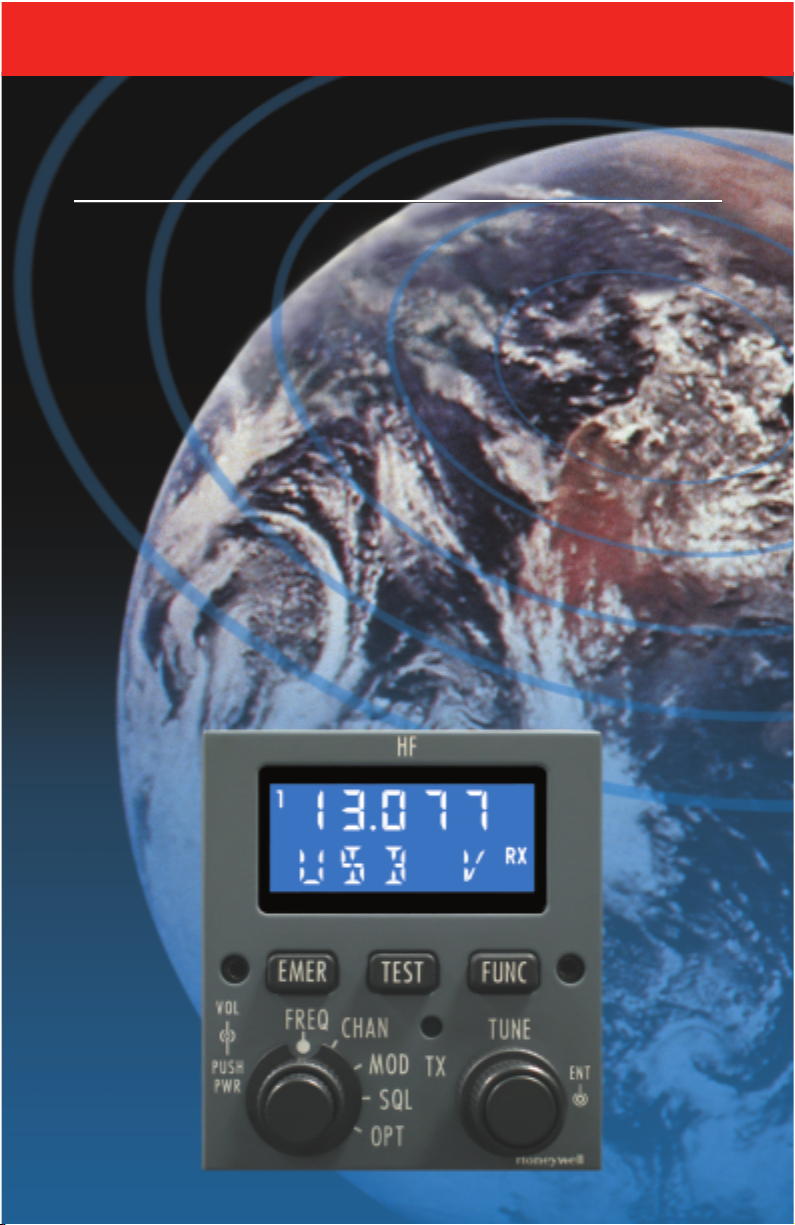
HF Communications System
(with PS440 Control Display Unit)
HF Communications System
(with PS440 Control Display Unit)
KHF 1050
KHF 1050
Pilot’s Guide
Pilot’s Guide
N
Page 2

WARNING
The enclosed technical data is eligible for export under License Designation NLR
and is to be used solely by the individual/organization to whom it is addressed.
Diversion contrary to U.S. law is prohibited.
COPYRIGHT NOTICE
Copyright ©2003 Honeywell International Inc. All rights reserved.
Reproduction of this publication or any portion thereof by any means without the
express written permission of Honeywell International Inc. is prohibited. For further information contact the Manager, Technical Publications; Honeywell; One
Technology Center; 23500 West 105th Street; Olathe, Kansas 66061.
Telephone: (913) 782-0400.
Page 3

KHF 1050 (PRIMUS HF 1050) SYSTEM DESCRIPTION . . . . . . . . . . . . . . . .1
SYSTEM OPERATION . . . . . . . . . . . . . . . . . . . . . . . . . . . . . . . . . . . . . . . .1
PS440 CONTROL DISPLAY UNIT . . . . . . . . . . . . . . . . . . . . . . . . . . . . . .1
CONTROLS . . . . . . . . . . . . . . . . . . . . . . . . . . . . . . . . . . . . . . . . . . . .1
DISPLAY . . . . . . . . . . . . . . . . . . . . . . . . . . . . . . . . . . . . . . . . . . . . . .2
PS440 OPERATION . . . . . . . . . . . . . . . . . . . . . . . . . . . . . . . . . . . . . . . .2
ON/OFF/VOLUME . . . . . . . . . . . . . . . . . . . . . . . . . . . . . . . . . . . . . . . .2
FAIL MODE . . . . . . . . . . . . . . . . . . . . . . . . . . . . . . . . . . . . . . . . . . . .3
SQUELCH . . . . . . . . . . . . . . . . . . . . . . . . . . . . . . . . . . . . . . . . . . . . . .3
DIRECT TUNING A FREQUENCY . . . . . . . . . . . . . . . . . . . . . . . . . . . .4
Selecting the Proper Operating Frequency . . . . . . . . . . . . . . . . . . .4
Simplex Direct Tuning . . . . . . . . . . . . . . . . . . . . . . . . . . . . . . . . . .5
Semi-Duplex Direct Tuning . . . . . . . . . . . . . . . . . . . . . . . . . . . . . .6
MODE SELECTION . . . . . . . . . . . . . . . . . . . . . . . . . . . . . . . . . . . . . . .7
CHANNEL OPERATION AND PROGRAMMING . . . . . . . . . . . . . . . . . .8
Channel Operation . . . . . . . . . . . . . . . . . . . . . . . . . . . . . . . . . . . . .8
Emergency Channel Operation . . . . . . . . . . . . . . . . . . . . . . . . . . . .8
Channel Programming . . . . . . . . . . . . . . . . . . . . . . . . . . . . . . . . .10
Clearing User Programmed Channels . . . . . . . . . . . . . . . . . . . . .10
Emergency Channel Programming . . . . . . . . . . . . . . . . . . . . . . . .11
Clearing User Programmed Emergency Channels . . . . . . . . . . . .12
CLARIFIER . . . . . . . . . . . . . . . . . . . . . . . . . . . . . . . . . . . . . . . . . . . .12
MARITIME RADIOTELEPHONE NETWORK CHANNEL OPERATION .12
TRANSMIT POWER SELECTION . . . . . . . . . . . . . . . . . . . . . . . . . . .13
DATA COMMUNICATIONS . . . . . . . . . . . . . . . . . . . . . . . . . . . . . . . .13
AVIATION SERVICES AVAILABLE TO HF USERS . . . . . . . . . . . . . . . . .14
ARINC AIR/GROUND INTERNATIONAL RADIO SERVICES . . . . . . . .14
UNIVERSAL WEATHER AND AVIATION INC/HOUSTON RADIO . . . .14
WLO MARINE RADIO . . . . . . . . . . . . . . . . . . . . . . . . . . . . . . . . . . . .14
Table of Contents
i
KHF 1050/PS440 Pilot's Guide
Revision 1 May/2003
Page 4

APPENDIX A . . . . . . . . . . . . . . . . . . . . . . . . . . . . . . . . . . . . . . . . . . . . . .15
CHARACTERISTICS OF HF SSB COMMUNICATIONS . . . . . . . . . . . . .15
HF SSB COMMUNICATIONS . . . . . . . . . . . . . . . . . . . . . . . . . . . . . .15
FREQUENCY . . . . . . . . . . . . . . . . . . . . . . . . . . . . . . . . . . . . . . . . . . .15
SKYWAVE PROPAGATION - WHICH FREQUENCY TO USE? . . . . . .16
WHY SINGLE SIDEBAND IS IMPORTANT IN HF COMMUNICATIONS .21
AMPLITUDE MODULATION (AM) . . . . . . . . . . . . . . . . . . . . . . . . . .21
SINGLE SIDEBAND OPERATION . . . . . . . . . . . . . . . . . . . . . . . . . . .21
SUPPRESSED CARRIER VS. REDUCED CARRIER . . . . . . . . . . . . . .22
SIMPLEX AND SEMI-DUPLEX OPERATION . . . . . . . . . . . . . . . . . . .22
APPENDIX B . . . . . . . . . . . . . . . . . . . . . . . . . . . . . . . . . . . . . . . . . . . . . .23
MARITIME RADIOTELEPHONE CHANNEL DESIGNATIONS . . . . . . . . .23
Table of Contents
ii
KHF 1050/PS440 Pilot's Guide
Revision 1 May/2003
Page 5
KHF 1050 (PRIMUS HF 1050) SYSTEM DESCRIPTION
The KHF 1050 System (also known as the Primus HF 1050 System) is a
solid-state high frequency (HF) single sideband (SSB) transceiver system providing voice and data communication. Data communication is
through an external modem.
This publication describes the operation of the KHF 1050 HF
Communication System using the PS440 Control Display Unit (CDU).
SYSTEM OPERATION
PS440 CONTROL DISPLAY UNIT
CONTROLS
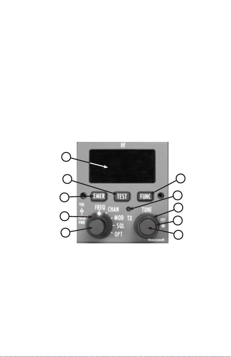
The control functions of the PS440 are described in the following sections. Refer to Figure 1 for control locations.
Revision 1 May/2003 KHF 1050/PS440 Pilot’s Guide
1
Figure 1 - PS440 Controls
5
4
3
6
7
8
2
9
1
1 ON/OFF/Volume - Inner concentric knob. Press ON and press OFF.
Rotate to adjust volume.
2 Function Selector - Outer concentric knob. Rotate to select FREQ,
CHAN, MOD, SQL or OPT.
3 Emergency Channel Access Button - Press to gain access to
selection of emergency channels.
4 Functional Test Button - Press to initiate the built-in functional test.
5 Display Area - Digital display of frequencies, modes, channel numbers,
etc.
6 Sub-Function Select Button - Press to enter and select sub-functions.
7 Transmit Lamp - Illuminates when the system is transmitting.
8 Outer Selector Knob - Right outer concentric knob. Rotate to select
frequency, channel numbers, etc.
9 Inner Selector Knob - Right inner concentric knob. Rotate to select
frequency, channel numbers, etc.
10 Enter Button - Press to store data entries.
10
Page 6
Revision 1 May/2003
KHF 1050/PS440 Pilot’s Guide
DISPLAY
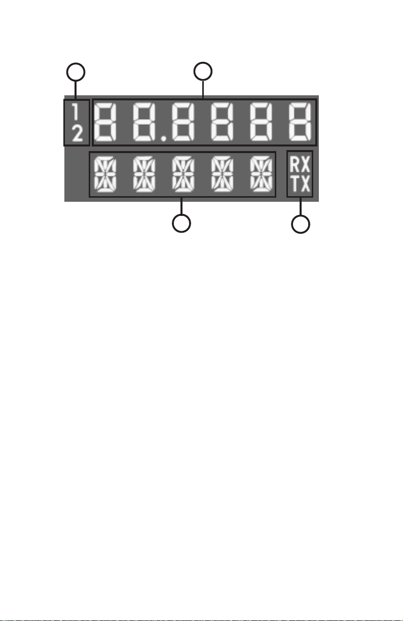
Figure 2 defines the display areas.
PS440 OPERATION
ON/OFF/VOLUME
This smaller inner concentric knob (lower left) turns the system off and
on and controls volume. Pressing the inner knob turns the system on.
Pressing and holding the inner knob for 3 seconds turns the system off.
Rotating the inner knob clockwise increases volume. Counterclockwise
rotation decreases volume.
A built-in functional test is performed at power-up. The test should take
no longer than 30 seconds. If any problems are found, the system will
enter a Fail Mode.
The functional test may also be initiated by pressing and holding the
TEST button for three seconds. After three seconds, all display segments will be lit and the TX lamp will be illuminated. Allow at least 30
seconds for the test to complete. Press the TEST button again to exit
the test mode.
NOTE: At temperatures below -30˚C, allow the system a one minute
warm-up period after turn-on before transmitting.
2
Figure 2 - PS440 Display
1
2
4
1 Controller Number - Identifies the designation of the Control Display
Unit. Pilot’s side would normally be #1 and co-pilot #2.
2 Frequency Display - Indicates transmit or receive frequency.
3 Transmit or Receive - RX indicates displayed data pertains to receive
state. TX indcates data pertains to transmit state.
4 Information Display - Alpha-numeric characters conveying information
such as selected mode, channel number, squelch type/value, power
setting, clarifier setting, etc.
3
Page 7

FAIL MODE
If there is a failure in the PS440 the bottom row on the display will show
PANEL.
A failure elsewhere in the system will display FAIL (ACP in the case of
an Antenna Coupler pressure warning or failure) on the top row of the
display.
Depending on the nature of the failure, the system will display the following on bottom row of the display:
RXEX Receiver/Exciter Failure
PA Power Amplifier Failure
CPLR Antenna Coupler Failure
PRS W Antenna Coupler Pressure Warning (service will be required
soon)
PRS F Antenna Coupler Pressure Failure (transmitter power has been
reduced to 50 Watts. The antenna coupler requires service.)
SQUELCH
The KHF 1050 system offers four types of squelch with corresponding
values as follows:
SBH - (Syllabic Squelch High). This is the default squelch and is usually
best for normal voice communications. A syllabic squelch opens upon
receiving a signal with voice-like characteristics while ignoring other signals. With syllabic squelch, there is the possibility that the first syllable of
a voice reception may be partially squelched. The possible adjustment
levels are open, meaning no squelch action (OPN), minimum (MIN),
medium (MED) and maximum (MAX).
SBL - (Syllabic Squelch Low). This squelch is also a syllabic squelch
and is intended for voice communications where the desired signal is
very weak and noisy. This squelch is more prone to opening on noise
than the SBH squelch. The possible adjustment levels are open (OPN),
minimum (MIN), medium (MED) and maximum (MAX).
SQH - (Signal/Noise Squelch High). This is a traditional signal-to-noise
squelch best suited for listening to non-voice signals, or voice signals
that do not respond well to one of the syllabic squelches. Compared to
the syllabic squelches, a higher signal level is generally required for this
squelch to perform well. The possible adjustment levels are 1-32, where
1 is open squelch.
SQL - (Signal Level Squelch). This is a signal strength squelch which
opens on any strong input signal. It opens quickly on strong signals, but
also opens on strong noise or static. Use of SQL is recommended for
use only with strong signals and under low noise conditions. This
Revision 1 May/2003 KHF 1050/PS440 Pilot’s Guide
3
Page 8
Revision 1 May/2003
4
KHF 1050/PS440 Pilot’s Guide
squelch is well suited for music broadcasts. The possible adjustment levels are
1-32, where 1 is open squelch.
Perform the following steps to set the
squelch:
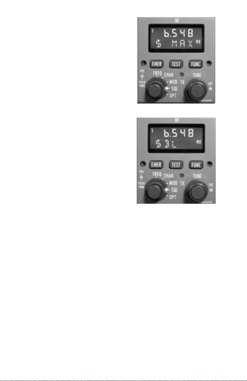
1. Rotate the left outer concentric knob to
the SQL position. See Figure 3. The
value of the active squelch is displayed on
the right bottom row of the display. At system power-up the last selected squelch will
be active.
2. Press the FUNC button to cycle through
the four types of squelch. Turn the right
inner knob to select the desired value for
the selected squelch type. See Figure 4.
NOTE: It is important to know that squelch
operation in HF is not as predictable as in
conventional VHF communications. It is
not unusual for conditions to make it
necessary to make squelch inactive
(open) to maintain satisfactory reception. Otherwise the signal may fade below
the threshold you have set on the squelch,
and you may miss an important message
from a ground station. This is unlike VHF
receiver squelch where you are normally
dealing with a strong, non-fading signal. For this reason SELCAL may be
a desirable option.
DIRECT TUNING A FREQUENCY
SELECTING THE PROPER OPERATING FREQUENCY
Long range communications are possible due to the signals being
reflected back to earth by the ionosphere. The ionosphere’s ability to
propagate HF radio signals is dependent on many factors. These
include time of day, season of the year, solar activity and latitude.
Various frequencies propagate differently as they travel through the
ionosphere. See Appendix A for more information.
It is important that the selected operating frequencies be appropriate for
the distance between the aircraft and the ground station or other aircraft.
If communications cannot be established on a particular frequency,
attempt to establish communications on other appropriate frequencies.
Table 1 summarizes the typical propagation distances of various frequencies. Occasionally, propagation distances significantly different
from Table 1 may be observed.
Figure 4
Figure 3
Page 9
In direct tune operation, the pilot may select directly any of 280,000 frequencies in the range of 2.0 to 29.999 or 29.9999 MHz. Installation configuration may limit the upper frequency to 22.999 or 22.9999 MHz.
There are two types of frequency operation. “Simplex” is tuning the
same frequency for receive and transmit. “Semi-duplex” (sometimes
called “split”) is tuning two different frequencies, one for receive and one
for transmit. It is important to know the requirements of the desired
ground station when tuning these frequencies. Virtually all aviation services operate
on simplex.
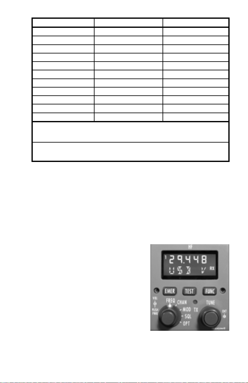
SIMPLEX DIRECT TUNING
1. Turn the left outer knob to FREQ. See
Figure 5. The frequency shown in the
upper row of the display is the receive frequency indicated by the RX on right of the
display.
2. Select the desired frequency using the
right inner and outer concentric knobs.
The outer knob changes the frequency in
.1 MHz increments. The inner knob changes the frequency in .001 MHz
(1 KHz) increments or .0001 MHz (100 Hz) increments, depending on
the configuration selected when the system was installed.
Revision 1 May/2003 KHF 1050/PS440 Pilot’s Guide
5
Figure 5
Frequency Band (MHz) Daytime Distance (Miles) Nighttime Distance (Miles)
2.8 & 3.0 Up to 100; Often unusable Up to 400
3.4 Up to 150; Often unsable Up to 800
4.4 Up to 200 Up to 1000
5.5 Up to 300 100 to 1200
6.5 100 to 600 200 to 1500
8.8 200 to 800 400 to 1500 or greater
10.0 300 to 1000 500 to 1800 or greater*
11.1 400 to 1200 600 to 1800 or greater*
13.3 600 to 1500 or greater Often unusable
17.9 700 to 1800 or greater* Often unusable
21.9 900 to 1800 or greater* Often unusable
The transition between daytime and nighttime distances may occur gradually
over a several hour period. During this transition, communication distances
between the daytime and nighttime distances listed will generally be realized.
* At times,communication may not be possible on this band during this timeframe. However, during periods of good propagation, worldwide communications may be realized.
Table 1 - Typical HF Signal Propagation Distance for Common
Aviation Bands
Page 10
Revision 1 May/2003
KHF 1050/PS440 Pilot’s Guide
6
The transmit frequency will automatically track the receive frequency
when tuning, providing for simplex operation. To verify the transmit frequency, press and hold the ENT button located on the end of the right
knobs. RX and TX will be illuminated on the display and the transmit frequency will be displayed in the upper row.
3. Tune the antenna coupler. Momentarily press the push-to-talk button
to initiate antenna tuning. During the tuning process the TX lamp (just
below the TEST button) will flash and the frequency numbers will blank.
A tune tone will be heard, if enabled during system installation. When
the TX lamp stops flashing and the frequency reappears, the antenna
tuning cycle is complete and you are ready to transmit on the selected
frequency.
In the event the antenna coupler is unable to tune to the selected frequency, the frequency digits and the TX lamp will flash. If enabled, a
tune tone will sound intermittently. Press push-to-talk once or twice to
clear the fault or initiate another tune cycle attempt. The fault may also
be cleared by selecting a different frequency. After the new frequency is
selected, press the push-to-talk to tune the antenna coupler.
NOTE: The KHF 1050 stores the antenna coupler tune information for
previously tuned frequencies. If the antenna coupler was previously
tuned for the current frequency (or nearby frequency) the antenna coupler may not need to be tuned and transmission may begin immediately.
It is advisable to always press the push-to-talk button after selecting a
new frequency to initiate antenna tuning. Otherwise poor reception may
be experienced or it may not be possible to hear a ground station which
is calling.
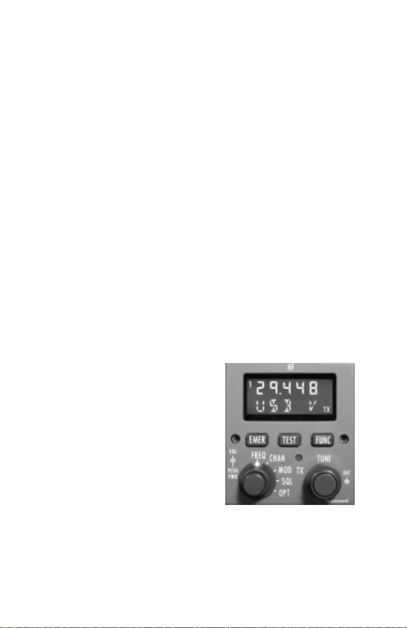
SEMI-DUPLEX DIRECT TUNING
If operating in a situation that requires a
transmit frequency that is different than the
receive frequency (semi-duplex) a different
transmit frequency may be tuned.
1. Turn the left outer knob to FREQ. See
Figure 5. The frequency shown in the
upper row of the display is the receive frequency indicated by the RX on right of the
display.
2. Press and hold the ENT button.
3. Momentarily press the FUNC button,
then release the ENT button. The transmit
frequency can now be tuned independent of the receive frequency. Note
that TX is now illuminated on the display indicating that the displayed frequency is the transmit frequency. See Figure 6.
Figure 6
Page 11
4. Select the desired frequency using the right inner and outer concentric
knobs. The outer knob changes the frequency in .1 MHz increments.
The inner knob changes the frequency in .001 MHz (1 KHz) increments
or .0001 MHz (100 Hz) increments, depending on the configuration
selected when the system was installed.
5. Press the ENT button again to accept the new transmit frequency. If
the ENT button is not pressed and the system detects no further activity,
the system will revert to the previous transmit frequency.
6. Momentarily press push-to-talk to tune the antenna to the new channel
frequency.
NOTE: Always press the push-to-talk button after selecting a new frequency to initiate antenna tuning. Otherwise poor reception may be
experienced or it may not be possible to hear a ground station which is
calling.
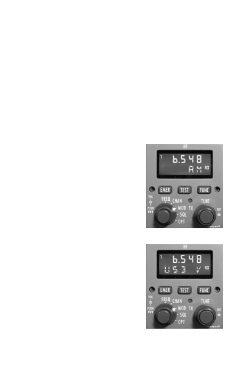
MODE SELECTION
Emission Mode selection options include
Upper Sideband Voice (USB V), Lower
Sideband Voice (LSB V), Upper Sideband
Data (USB D), Lower Sideband Data (LSB
D), AM Voice (AM) and Reduced Carrier
(RC). Upper Sideband Voice will always
be available, but availability of the other
choices depends upon options selected
when the system was installed.
It is important to know the correct Mode
that matches the requirements of the
ground station. Upper Sideband Voice
and Data are considered the standard and
most commonly used. Some older stations may still use AM Voice. Also, AM
Voice is best for listening to voice broadcast stations. Some stations have the ability to lock on to a transmitted carrier to
avoid frequency errors. When communicating with one of these stations, Reduced
Carrier may be used.
To select the desired mode turn the left
outer knob to MOD. See Figure 7.
Pressing the FUNC button will toggle
between modes. Also, turning the right
inner or outer knob will advance through
the modes. See Figure 8.
Revision 1 May/2003 KHF 1050/PS440 Pilot’s Guide
7
Figure 7
Figure 8
Page 12
Revision 1 May/2003
KHF 1050/PS440 Pilot’s Guide
8
CHANNEL OPERATION AND PROGRAMMING
The 100 programmable channels available with the PS440 Control
Display Unit are easily programmed on the ground or in the air.
Channels are 00-99. Channel 00 is always tuned to 2.182 MHz. In addition, there are six emergency channels, five of which can be programmed. Channels are EMR 2 - EMR 6. EMR 1 is tuned to 2.182
MHz. It is the default channel and cannot be changed.
Simplex and semi-duplex frequency tuning also applies when programming channels. It is important to know the requirements of the desired
ground station when programming frequencies.
In addition to assigning frequencies to a channel, a mode is also
assigned.
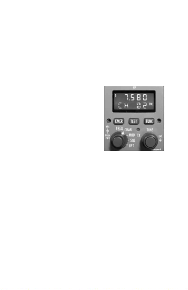
Channel Operation
The following steps illustrate how to select
already programmed channels.
1. Turn the left outer knob to CHAN as
shown in Figure 9. The last selected channel will be displayed.
2. Turn the right inner or outer knob to
select the desired channel number.
3. Momentarily press push-to-talk to tune
the antenna to the new channel frequency.
Emergency Channel Operation
Emergency channels typically use simplex operation. However channels
2 - 6 can be programmed for semi-duplex operation.
The emergency channels are programmed at the factory according to
Table 2. Only channels 2 - 6 may be changed.
Figure 9
Page 13
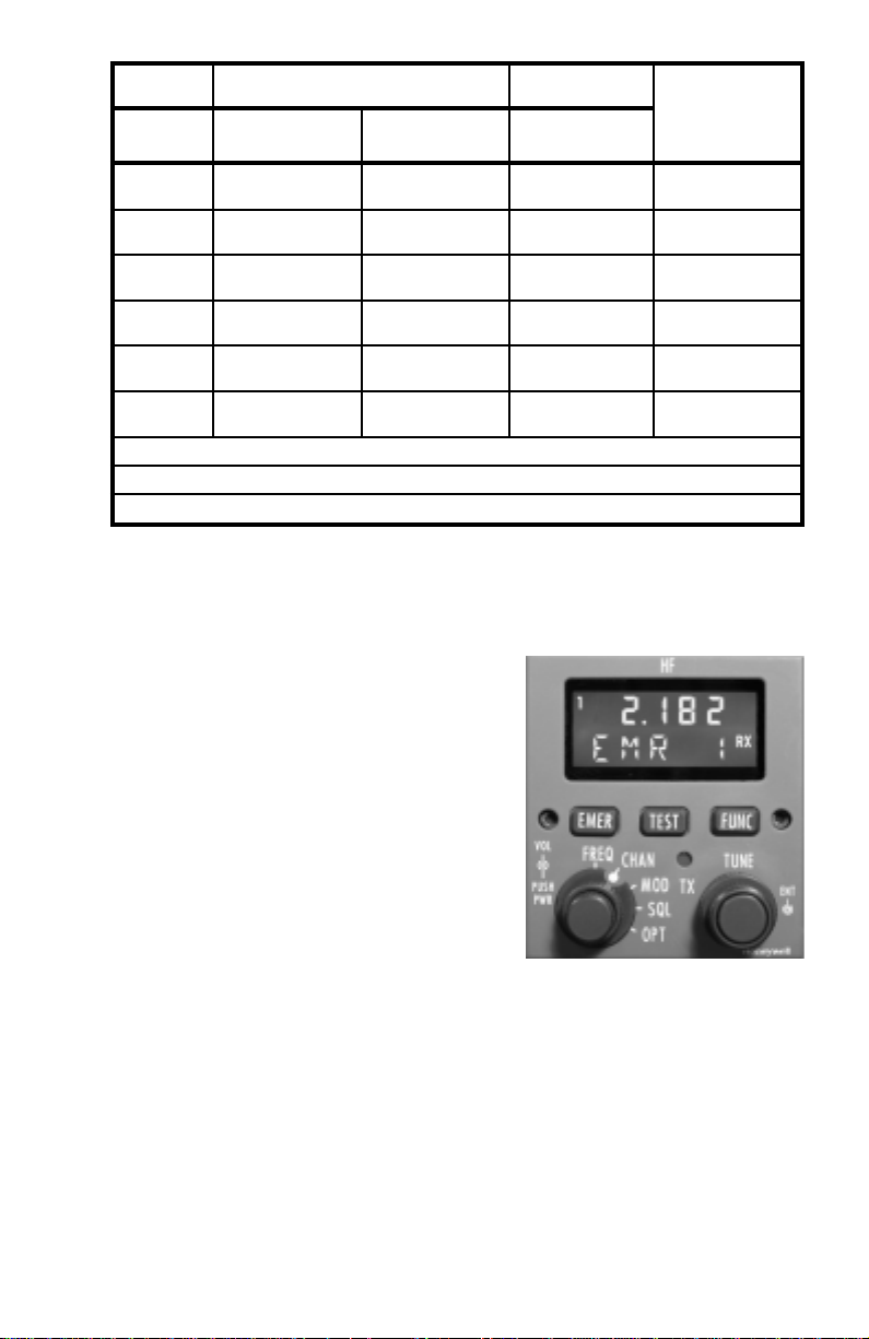
The following steps illustrate how to select already programmed emergency channels.
1. Press and hold the EMER button for
approximately 2 seconds. The display will
appear as shown in Figure 10 with EMR 1
as the default channel.
2. If other than EMR 1 is desired turn the
right inner or outer knob to select the
desired emergency channel number.
Even if the selected channel has previously been programmed for semi-duplex operation, simplex operation will initially be
selected. If desired, press the ENT button
to select semi-duplex operation. SPLT will
be displayed for two seconds in the lower
part of the display. Press the ENT button
again to return to simplex operation. SIMP will now be displayed for two
seconds in the lower part of the display. Repeated pressing of the ENT
button will toggle between simplex and semi-duplex operation.
3. Momentarily press push-to-talk to tune the antenna to the new channel
frequency.
4. Press the EMER button to exit the emergency channels.
Revision 1 May/2003 KHF 1050/PS440 Pilot’s Guide
9
Frequency (kHz) ITU Channel Assignment
Channel Simplex Tune
(Default)
Semi-Duplex
(also called Split)
EMR 1 2182 Simplex Only
----
International Distress
and Calling.
EMR 2 4125 Rx: 4417 Tx: 4125 421
International Distress
and Calling.
EMR 3 6215 Rx: 6516 Tx: 6215 606
Maritime Distress
and Calling.
EMR 4 8291 Simplex Only 833
Maritime Distress
and Calling.
EMR 5 12290 Rx: 13137 Tx: 12290 1221
Maritime Distress
and Calling.
EMR 6 16420 Rx: 17302 Tx: 16420 1621
Maritime Distress
and Calling.
Simplex operation is typically used for communicating with other aircraft, ships or emergency ground stations.
Semi-Duplex operation may be used for communications with Maritime Radiotelephone Network ground stations.
Upper Sideband Voice is the only emission mode available when using emergency channels.
Table 2 - PS440 Emergency Channels (Factory Default Programming)
Figure 10
Page 14

Revision 1 May/2003
KHF 1050/PS440 Pilot’s Guide
Channel Programming
The following steps show how to program channels into memory.
1. Turn the left outer knob to CHAN. The last selected channel will be
displayed. Refer to Figure 9.
2. Press and hold the FUNC button for approximately 3 seconds. The
channel window will start flashing indicating entering programming mode.
3. Turn the right inner or outer knob to select the desired channel number.
4. Press the ENT button on the end of the right knob. The selected
channel is stored and the receive frequency will begin flashing.
5. Use the right inner and outer knobs to select the desired receive frequency. Remember to check ground station requirements as to the
need for simplex or semi-duplex operation.
6. Press the ENT button. The selected receive frequency is stored and
the Mode will begin flashing.
7. Turn the right inner or outer knob to select the desired emission mode.
8. Press the ENT button. The selected Mode is stored and the transmit
frequency will now begin flashing.
9. If the channel requires simplex operation, again press the ENT button
to store the automatically displayed transmit frequency. The channel
window now displays the next available channel number.
10. If the channel requires semi-duplex operation, use the right inner and
outer knobs to select the desired transmit frequency. Press the ENT button. The transmit frequency is stored and the channel window now displays the next available channel number. Again, check the ground station requirements as to the need for simplex or semi-duplex operation.
11. Press and hold the FUNC button for approximately 3 seconds to exit
programming. The display reverts to the last channel programmed.
Clearing User Programmed Channels
Perform the following steps to clear user programmed channels from
memory.
1. Set the left outer knob to CHAN.
2. Press and hold the left inner knob for 3 seconds to the system off.
3. Press and hold the EMER, TEST and FUNC buttons simultaneously
while pressing the left inner knob to turn the system back on.
4. Continue holding the three buttons until CLMEM is displayed in the
lower part of the display.
10
Page 15

5. While still holding the three buttons, press the ENT button. All previously programmed channels are now deleted.
Emergency Channel Programming
Following steps show how to program emergency channels into memory.
1. Press and hold the EMER button for approximately 2 seconds. The
display will appear as shown in Figure 10 with EMR 1 as the default
channel.
2. Press and hold the FUNC button for approximately 3 seconds. The
channel window will start flashing indicating entering programming mode.
3. Turn the right inner or outer knob to select the desired channel number.
4. Press the ENT button on the end of the right knob. The selected
channel is stored and the receive frequency will begin flashing.
5. Use the right inner and outer knobs to select the desired receive frequency. Remember to check ground station requirements as to the
need for simplex or semi-duplex operation.
6. Press the ENT button. The selected receive frequency is stored and
the Mode will begin flashing. Only USB V is available when programming an emergency channel.
7. Press the ENT button. The selected Mode is stored and the transmit
frequency will now begin flashing.
8. If the emergency channel requires simplex operation, again press the
ENT button to store the automatically displayed transmit frequency. The
channel window now displays the next available emergency channel
number.
9. If the channel requires semi-duplex operation, use the right inner and
outer knobs to select the desired transmit frequency. Press the ENT button. The transmit frequency is stored and the channel window now displays the next available emergency channel number. Again, check the
ground station requirements as to the need for simplex or semi-duplex
operation.
NOTE: On any Emergency Channel with separate receive and transmit
frequencies, simplex operation will occur on the programmed channel’s
transmit
frequency when the channel is first selected.
10. Press the EMER button to exit.
Revision 1 May/2003 KHF 1050/PS440 Pilot’s Guide
11
Page 16

12
Revision 1 May/2003
KHF 1050/PS440 Pilot’s Guide
Clearing User Programmed Emergency Channels
Perform the following steps to revert back to the factory programmed
emergency channels.
1. Press the EMER button to enter the emergency channels.
2. Press and hold the left inner knob for 3 seconds to the system off.
3. Press and hold the EMER, TEST and FUNC buttons simultaneously
while pressing the left inner knob to turn the system back on.
4. Continue holding the three buttons until CLEMR is displayed in the
lower part of the display.
5. While still holding the three buttons, press the ENT button. All factory
programmed emergency channels are now restored.
CLARIFIER
The purpose of the Clarifier is to help eliminate the unnatural “tinny sound” found at
times with SSB audio voice quality as a
result of off-frequency ground station
transmissions. The Clarifier works by
allowing frequency adjustment of ±250 Hz
whether the channel involved is semiduplex or simplex tuned. It is not normally
used in the AM mode.
Long range HF signals received under less
than optimum propagation conditions may
still vary in quality and volume.
To use clarifier, perform the following steps:
1. Turn the left outer knob to OPT. The Clarifier will be displayed first,
denoted by the C as shown in Figure 11.
2. Turn the right inner knob to adjust the Clarifier frequency up or down
for reception.
3. Select any other function to exit the Clarifier. When another frequency
or channel is selected the Clarifier value will return to 000.
MARITIME RADIOTELEPHONE NETWORK (PUBLIC CORRESPONDENCE) CHANNEL OPERATION
All 246 ITU public correspondence channels in the maritime radiotelephone network are programmed permanently in the electronic memory of
the KHF 1050 System. These channels may be used by aircraft to make
telephone calls through the High-Seas-Operator Network. Refer to
Appendix B for channels and frequencies.
To use the ITU channels perform the following steps:
Figure 11
Page 17

1. Turn the left outer knob to OPT. The
Clarifier will be displayed first, denoted by
the C as shown in Figure 11.
2. Press the FUNC button until the last
tuned ITU channel appears in the lower
right of the display as shown in Figure 12.
The lower left will be blank.
3. Turn the right inner or outer knob to
select the desired ITU channel.
4. Momentarily press push-to-talk to tune
the antenna to the new channel frequency.
5. Select any other function to exit.
TRANSMIT POWER SELECTION
The KHF 1050 System transmit power can be adjusted for optimum
communication quality dictated by conditions such as ionospheric conditions and distance to station. Available settings are Minimum (MIN),
Medium (MED) and Maximum (MAX).
MIN = 50 Watts
MED = 100 Watts
MAX = 200 Watts
To change the transmit power, perform the
following steps:
1. Turn the left outer knob to OPT. The
Clarifier will be displayed first, denoted by
the C as shown in Figure 11.
2. Press the FUNC button until transmit
power is selected, denoted by the P and a
value in the lower part of the display as
shown in Figure 13.
3. Turn the right inner or outer knob to select the desired transmitter
power output.
4. Select any other function to exit.
DATA COMMUNICATIONS
The KHF 1050 System will transmit and receive data, such as fax transmissions, etc. Data communication requires an external modem be
installed with the system.
Before transmitting or receiving data, select the appropriate Mode (USB
D, LSB D or possibly AM) as previously discussed in Mode Selection.
Check the requirements of the desired station.
Revision 1 May/2003 KHF 1050/PS440 Pilot’s Guide
13
Figure 12
Figure 13
Page 18

14
Revision 1 May/2003
KHF 1050/PS440 Pilot’s Guide
AVIATION SERVICES AVAILABLE TO HF USERS
In addition to using the KHF 1050 for air traffic control functions, HF
users can also take advantage of other HF services.
ARINC AIR/GROUND INTERNATIONAL RADIO SERVICES
This service can be used to coordinate flight and ground activities,
advise dispatch of events, provide radio checks and a variety of other
related services.
Arrangements can be made with ARINC by calling 1-800-633-6882 in
the United States. Internationally, use the AT&T Access Code + 1-800633-6882. Or visit www.arinc.com/products/voice_data_comm/.
UNIVERSAL WEATHER AND AVIATION INC/HOUSTON RADIO
This service can be used to forward messages, perform phone patches,
provide flight following, give weather updates, provide radio and SELCAL
checks and forward ETAs to appropriate government agencies.
To make arrangements with Universal/Houston Radio, call 1-800-2315600 extension 8311 in the United States. Internationally, call 713-9441622 extension 8311. Or visit www.univ-wea.com.
WLO MARINE RADIO
This service in Mobile, Alabama allows aircraft equipped with the KHF
1050 system to make telephone calls through the Maritime
Radiotelephone Network (High-Seas Operator). Assigned a callsign of
WLO, this station operates on approximately twelve of the 246 channels
permanently programmed into the KHF 1050 system (see the ealier section on the Maritime Radiotelephone Network and Appendix A).
Information about High-Seas Operator stations in other parts of the world
can also be obtained from WLO.
Contact by calling 251-666-5110 or visit www.wloradio.com
Page 19

APPENDIX A
CHARACTERISTICS OF HF SINGLE SIDEBAND COMMUNICATIONS
HF SSB COMMUNICATIONS
High frequency single side band communications achieve reliable long
range transmission and reception over distances of thousands of miles.
The primary reason is due to skywave propagation which allows HF
radio waves which are beamed toward outer space to be reflected back
toward the earth’s surface by the ionosphere. Another reason is
because of a transmission process known as single sideband which puts
all the transmitter’s power into sending just a radio wave containing the
intelligence to be communicated. Both of these make HF radio highly
useful to aircraft flying over water or desolate land areas when they are
out of reach of VHF communications which are limited to line of sight
transmissions.
FREQUENCY
The frequency of a radio wave is the number of cycles of that radio wave
which pass a given point within one second. The longer the wavelength,
the lower the frequency. The frequency is often expressed as cycles per
second, with one complete wave representing a cycle. The term hertz
(Hz) is more commonly used today to represent one cycle per second.
Expression of the measurement Hz has a shorthand of its own. When
thousands of Hz are expressed, they are designated kilohertz (kHz),
and millions of Hz as megahertz (MHz). Thus, the notation 29.9999
MHz represents a signal which is passing a given point at 29,999,900
cycles per second. Expressed in kHz, the same figure would read
29,999.9 kHz representing 29,999.9 thousand cycles per second. In
using HF, you will encounter both MHz and kHz notations for frequencies.
The high frequency (HF) band covers from 2.0 MHz to 30 MHz (2,000
kHz to 30,000 kHz). The HF band lies between the medium frequency
(MF) band and the very high frequency (VHF) band. Pilots are familiar
with the characteristics of MF frequencies through the use of ADF equipment and know that these signals hug the ground and are sensitive to
variations in terrain and to atmospheric disturbances. On the other hand,
pilots know that VHF frequencies such as are used in VOR navigation
and normal communications with Air Traffic Control facilities generally
travel line-of-sight range and are not greatly affected by atmospheric disturbances. As will be discussed next, HF has its own characteristics
which allow long range communications to take place.
Revision 1 May/2003 KHF 1050/PS440 Pilot’s Guide
15
Page 20

16
Revision 1 May/2003
KHF 1050/PS440 Pilot’s Guide
SKYWAVE PROPAGATION - WHICH FREQUENCY TO USE?
As mentioned earlier, HF’s primary method of travel or propagation is via
skywaves which are radio waves that start out radiating into space and
are reflected off the ionosphere back to the earth’s surface. This reflecting of signals makes communications possible over very long distancesunder ideal conditions, more than 4,000 miles and typically in excess of
2,000 miles-possible. Because of variations in the ionosphere, HF communications require more analysis of conditions and operational decisions (such as frequency selection) than VHF communications.
The ionosphere is a multi-layered band of electrically charged particles
surrounding the earth. It varies in height above the surface of the earth
from approximately 30 to over 400 miles. The height and intensity varies
from one location to the next and according to the season of the year
and the time of day.
Because HF radio waves depend upon the ionosphere for reflection,
their propagation is affected by changes in the ionosphere. It is changes
in the density of the electrically charged particles in the ionosphere which
cause propagation to improve or deteriorate. Since the ionosphere is
formed primarily by the action of the sun’s ultraviolet radiation, it’s thickness changes in relation to the amount of sunlight passing through it.
Sunlight-induced ionization increases the particle density during the day
and the absence of it reduces the particle density at night. At midday,
when the sun’s radiation is at its highest, the ionosphere’s thickness may
expand into four layers of ionized gas. During the nighttime hours, the
ionosphere diminishes, normally merging into just one layer.
Solar disturbances including solar flares and magnetic storms can cause
propagation of HF radio waves to deteriorate rapidly. HF signals can
also suffer interference from such atmospheric disturbances as precipitation and thunderstorms.
The net result of all these factors is that because the ionospheric and
atmospheric conditions are constantly changing, HF communications
can vary in quality and strength. The signal received on the KHF 1050
may be accompanied by a considerable amount of static from atmospheric disturbances, or it may fade in and out at times because each
radio wave which hits the changing ionosphere may be reflected differently. Your reception and transmission success may vary from loud and
clear to nonexistent depending on your selection of frequency and the
conditions in the atmosphere and the ionosphere. One of the best things
the pilot can do to assure the best possible HF communications, based
on existing HF propagation conditions, is to select the proper frequency.
A good rule of thumb for the time of day is that the higher frequencies
are best during daylight (10 to 29.9999 MHz) and lower frequencies work
best at night (2 to 10 Mhz).
Page 21
This rule of thumb can be explained by a mirror analogy. It is the electrically charged particles in the ionosphere which reflect or bend radio
waves back toward earth like a mirror reflects light. Sunlight induces ionization and increases the density of these particles in the ionosphere during the day. The mirror becomes thicker and it reflects higher frequencies better. When the sun goes down the density of charged particles
decreases and the ionosphere becomes a mirror that can only reflect
lower frequencies in the HF band.
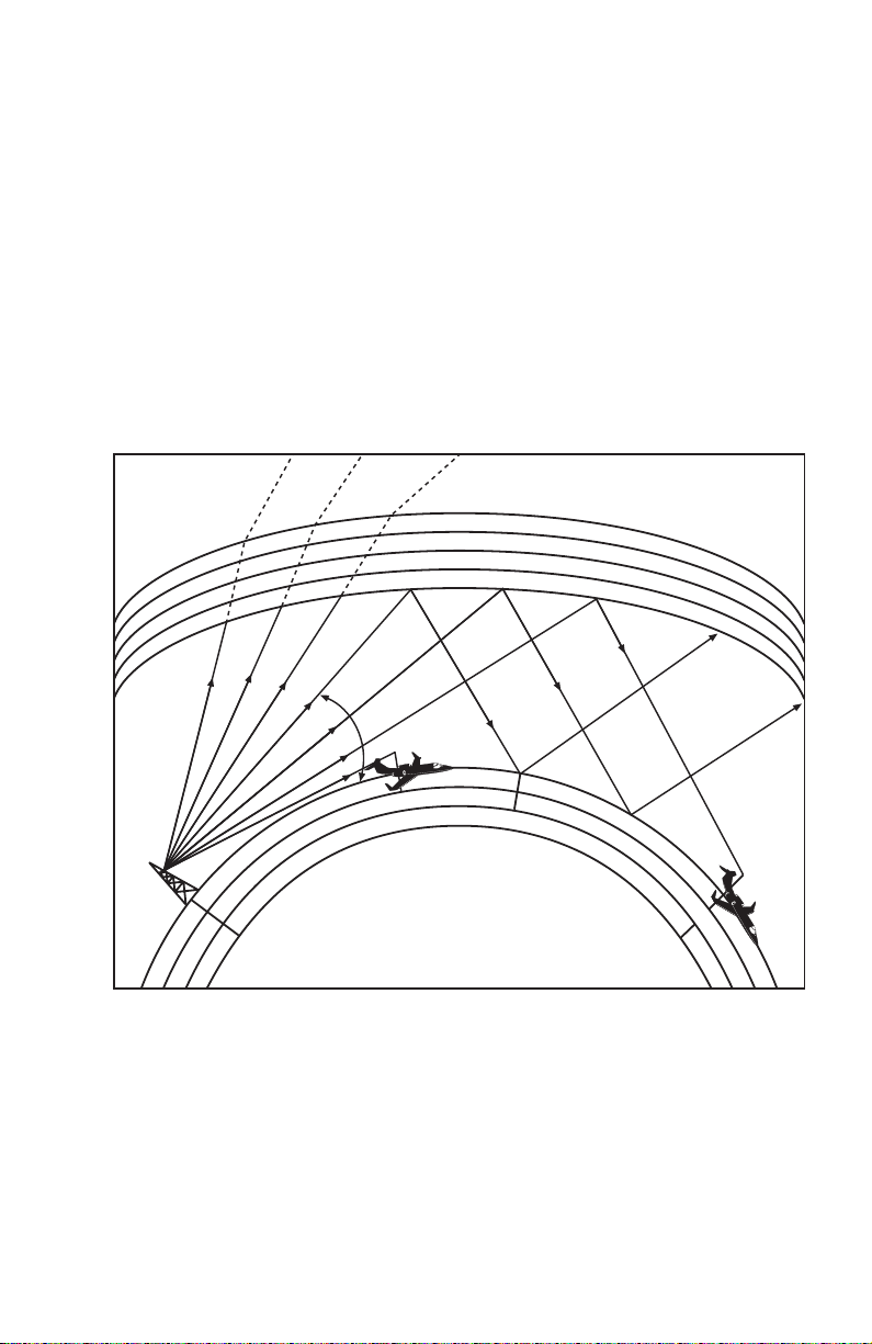
For any one particular frequency, as the angle at which an HF radio
wave hits a layer of the ionosphere is increased, a critical angle will be
reached from which the wave will just barely manage to be reflected
back to earth (Figure 1A). Waves entering at sharper angles than this
will pass through this layer of the ionosphere and be lost in space (or
may reflect off another layer of the ionosphere).
Changing the frequency under the same conditions will change the critical angle at which the HF radio waves will be reflected back to earth.
The highest frequency which is reflected back to the earth is called the
maximum useable frequency (MUF). The best HF communications are
usually obtained using a frequency as close to the MUF as possible
since radio waves higher than this frequency are not reflected and radio
waves lower than this frequency will be partially absorbed by the ionosphere.
Revision 1 May/2003 KHF 1050/PS440 Pilot’s Guide
17
Figure 1A - Effects Of Different Skywave Paths
REFRACTION
O
Z
E
I
V
K
A
S
W
M
D
U
N
M
I
U
N
I
O
M
R
G
IONOSPHERE
CRITICAL ANGLE
Q
E
N
A
T
S
I
D
P
S
DE
AIRCRAFT
T
Z
E
I
U
E
C
N
D
P
E
R
I
EARTH
O
N
E
A
T
H
S
K
Y
W
D
I
S
T
A
V
A
N
E
C
Z
E
O
N
AIRCRAFT
E
Page 22

18
Revision 1 May/2003
KHF 1050/PS440 Pilot’s Guide
You should also be aware of the possibility that you or the ground station
you are calling may be in a quiet zone. The linear distance from the
point of transmission to the point where the skywave returns to earth is
called the skip distance. There may be a quiet zone between the end of
the ground wave and the return of the skywave. No communication can
take place in this area. At any time, day or night, there is a “window” of
useable frequencies created by the reflecting properties of the ionosphere. At night this “window” will normally be in the lower range of HF
frequencies, and during the day it will be in the higher range of frequencies.
Normally you will not know what the MUF is at any particular time and
location unless you have a table of propagation forecasts. Just remember that the higher frequencies in the “window” of useable frequencies
are likely to be the most effective. The closer a frequency is to the MUF,
the better it is likely to be.
The effect of solar disturbances including solar flares and magnetic
storms is to change the particle density in the ionosphere. Therefore, the
“window” of useable frequencies may begin to close, with radio waves of
frequencies in the lower range dropping out first as they are absorbed by
the ionosphere.
Next, the radio waves of upper frequencies in the useable “window” may
start to penetrate the ionosphere and go into outer space. It is even possible for the entire “window” to close, particularly if you are flying in a
polar region in latitudes above 60 degrees north or 60 degrees south.
Solar disturbances have the most negative effects on HF communications in these regions.
If you are flying in polar regions and are having difficulty raising any
ground station located in the same region, remember this: even though
the “window” of useable frequencies may have closed in the polar
regions, another “window” may be open in regions closer to the equator
which are less affected by solar disturbances. Try calling a station closer
to the equator in latitudes lower than 60 degrees north or 60 degrees
south, and use a higher frequency. If you can raise a station in these
areas, that station may be able to relay your message.
There are even times when solar disturbances improve the usability of
higher frequencies in the HF band, particularly in equatorial regions.
Another phenomenon which occurs during solar disturbances may allow
you to communicate with a station even though the “window” is closed.
This is known as scatter propagation, in which a radio wave is broken up
in the ionosphere and scatters in various directions.
Because frequency propagation cannot be predicted with total accuracy,
ground stations responsible for aircraft HF communications will typically
operate on several different frequencies within the HF band. The pilot is
then able to choose the optimum communication frequency for the existing ionospheric conditions.
Page 23

One feature that will be particularly useful when a trial and error method
is used to find an HF frequency which is working well. This is the system’s capability to be programmed by the pilot with 100 channels using
the PS440 Control Display Unit. Rather than having to select the four to
six digits each time you want to try another frequency, you can preprogram the frequencies you need to contact a particular ground station.
Then if you call and fail to get through, you just change to another channel.
NOTE: It is advisable to program at least three frequencies for each station you plan to contact, in case one frequency suddenly becomes unusable. During times of solar disturbances, a useable frequency can fade
out in less than a minute. And the “window” of useable frequencies can
shift rapidly during solar disturbances or during sunset and sunrise when
the level of ionization in the ionosphere is changing rapidly.
Tables 1A and 2A show typical propagation distances due to reflection
from the ionosphere for various frequencies during different hours of the
day and for different seasons of the year. It may prove helpful in selecting the optimum HF frequency for the communications distance your
operation requires.
Revision 1 May/2003 KHF 1050/PS440 Pilot’s Guide
19
Table 1A - Typical Frequency Propagation Spring And Summer
Frequency (kHz)
Propagation (Miles)
Hours After Sunset
1 50 250 200 1000 500 3500 750 6000
2 100 600 250 1500 500 3500 750 6000
3 100 600 250 2000 500 3500
4 100 800 250 2500
5 100 1000 250 2500
6 100 1500 400 3000
7 100 1500 500 3500
8 250 2000 750 4000
9 250 2500 750 4000
10 250 2500 750 4000
11 100 1000 500 2500
Hours After Sunrise
1 100 500 400 2000
2 0 100 400 2000
3 0 100 250 1500
4 0 100 250 1500 500 1000
5 0 100 250 1500 500 1500
6 0 100 250 1500 500 2500 750 4000
7 0 100 250 1500 500 3500 750 4000
8 0 100 250 1500 500 3500 750 4000
9 0 100 250 1500 500 3500 750 4000
10 0 100 250 1500 500 3500 750 4000
11 0 100 150 500 500 3500 750 6000
12 0 200 150 500 500 3500 750 6000
13 50 250 150 750 500 3500 750 6000
4000 8000 12000 16000
Min Max Min Max Min Max Min Max
Page 24

20
Revision 1 May/2003
KHF 1050/PS440 Pilot’s Guide
Frequency (kHz)
Table 2A - Typical Frequency Propagation For Fall And Winter
Propagation (Miles)
Hours After Sunset
1 100 600 400 2000 500 3500 750 6000
2 100 800 400 2000 500 4000 750 6000
3 100 1000 400 2000 500 4000
4 100 1000 400 2500 500 4000
5 100 1000 400 3000 500 4000
6 100 1500 400 3500
7 250 2000 400 4000
8 250 2500 500 4000
9 500 3000 500 4000
10 500 4000 500 4000
11 500 3000 750 5000
12 250 2500 750 5000
13 250 1500 500 2500
Hours After Sunrise
1 100 1000 400 2000
2 100 500 400 2000
3 0 100 400 2000 3500 750 4000
4 0 100 400 2000 500 3500 750 4000
5 0 100 250 1500 500 3500 750 4000
6 0 100 250 1500 500 3500 750 4000
7 0 100 250 1500 500 4000 750 5000
8 0 100 250 1500 500 4000 750 5000
9 0 100 250 1500 500 4000 750 6000
10 0 100 250 1000 500 3500 750 6000
11 0 250 250 1500 500 3500 750 6000
4000 8000 12000 16000
Min Max Min Max Min Max Min Max
Page 25

WHY SINGLE SIDEBAND IS IMPORTANT IN HF COMMUNICATIONS
As mentioned earlier, there are two characteristics of HF SSB communications which allow long range capability. Skywave propagation has
been discussed in detail. The other characteristic is a transmission
process known as single sideband. Single sideband (SSB) high frequency (HF) communications was developed in the early 1950’s as a means
of increasing the effective range of HF signals. The KHF 1050 is capable of both amplitude modulation (AM) operation, such as is used in conventional VHF aircraft communications, and of SSB operation.
AMPLITUDE MODULATION (AM)
In order to understand SSB operation, a discussion of AM operation is
helpful. Amplitude Modulation (AM) is a transmission process in which
the selected frequency (called the carrier frequency) and two sidebands
(which are frequencies above and below the carrier frequency) are generated and transmitted. (Figure 2A.) It takes about two-thirds of the
transmitter’s power just to transmit the carrier frequency, yet the carrier
does not contain any of the intelligence to be communicated. Each of
these sidebands contains all the intelligence to be communicated.
Standard broadcast stations (550-1600 kHz) and short-wave broadcasts
use AM since it allows simpler receivers.
SINGLE SIDEBAND OPERATION
By electronically eliminating the carrier wave and one sideband, a single
sideband transmitter manages to pack all of its power in transmitting the
remaining single sideband. (Figure 3A). Either the upper sideband
(USB) or the lower sideband (LSB) can be used since each sideband
contains all the required intelligence. However, from a practical standpoint the USB is used almost exclusively in airborne HF SSB operations
and the LSB may be disabled. Upon receiving this SSB signal, the
receiver then generates the carrier frequency internally and combines it
with the one sideband in such a way that the intelligence (voice) can be
heard and understood by the pilot.
Revision 1 May/2003 KHF 1050/PS440 Pilot’s Guide
21
Figure 2A - Amplitude Modulation
AMPLITUDE MODULATION (AM)
fc = carrier frequency
fm = modulating frequency (voice)
fc-fm
LSB
fc fc+fm
USB
Page 26

22
Revision 1 May/2003
KHF 1050/PS440 Pilot’s Guide
NOTE: Lower sideband isn’t normally used in the aviation services.
During installation of the KHF 1050 system, LSB may be enabled for use
in regions or applications where its use authorized.
The result is that an SSB system has the effective transmit power of AM
units having many more times the transmitter power. Also, SSB communications allow the frequency band to be utilized more efficiently since
the space or “bandwidth” of only one sideband rather than two sidebands
is required to transmit the message.
SUPPRESSED CARRIER VS. REDUCED CARRIER
The single sideband (SSB) operation just described with the carrier frequency virtually eliminated is actually referred to as single sideband suppressed carrier. If just a small portion of the carrier is transmitted along
with the sideband, the operation is referred to as single sideband
reduced carrier.
SIMPLEX AND SEMI-DUPLEX OPERATION
The KHF 1050 is capable of both simplex and semi-duplex operation.
Simplex operation means that communication signals are transmitted
and received on the same frequency. Simplex operations are used
when communicating with Air Traffic Control (ATC), for example. Semiduplex operation means that messages are transmitted on one frequency and received on another. The HF operator selects separate transmit
and receive frequencies, then keys the microphone to transmit and
releases the push-to-talk switch to receive. Semi-duplex operation is
usually used for maritime radiotelephone (public correspondence) communications.
Figure 3A - Single Sideband
SINGLE SIDEBAND (SSB)
fc = carrier frequency
fm = modulating frequency (voice)
fc-fm
LSB
fc fc+fm
USB
Page 27

APPENDIX B
MARITIME RADIOTELEPHONE CHANNEL DESIGNATIONS
*THE AIRCRAFT/SHIP TRANSMIT FREQUENCIES FOR CHANNELS
428, 836 and 837 MAY VARY WORLDWIDE. The frequencies programmed into Honeywell products are those assigned by the FCC
(Federal Communication Commission, U.S.A.) for stations operating
under FCC authorization. Contact appropriate authorities for frequencies
authorized in other countries.
Revision 1 May/2003 KHF 1050/PS440 Pilot’s Guide
23
Table 1B - Maritime Radiotelephone Channel Designations (400s)
Channel Aircraft Receive Aircraft Transmit
(400s) (kHz) (kHz)
401 4357.0 4065.0
402 4360.0 4068.0
403 4363.0 4071.0
404 4366.0 4074.0
405 4369.0 4077.0
406 4372.0 4080.0
407 4375.0 4083.0
408 4378.0 4086.0
409 4381.0 4089.0
410 4384.0 4092.0
411 4387.0 4095.0
412 4390.0 4098.0
413 4393.0 4101.0
414 4396.0 4104.0
415 4399.0 4107.0
416 4402.0 4110.0
417 4405.0 4113.0
418 4408.0 4116.0
419 4411.0 4119.0
420 4414.0 4122.0
421 4417.0 4125.0
422 4420.0 4128.0
423 4423.0 4131.0
424 4426.0 4134.0
425 4429.0 4137.0
426 4432.0 4140.0
427 4435.0 4143.0
428* 4351.0 4160.0
Page 28

24
Revision 1 May/2003
KHF 1050/PS440 Pilot’s Guide
Channel Aircraft Receive Aircraft Transmit
Table 2B - Maritime Radiotelephone Channel Designations (600s)
Table 3B - Maritime Radiotelephone Channel Designations (800s)
(600s) (kHz) (kHz)
601 6501.0 6200.0
602 6504.0 6203.0
603 6507.0 6206.0
604 6510.0 6209.0
605 6513.0 6212.0
606 6516.0 6215.0
607 6519.0 6218.0
608 6522.0 6221.0
Channel Aircraft Receive Aircraft Transmit
(800s) (kHz) (kHz)
801 8719.0 8195.0
802 8722.0 8198.0
803 8725.0 8201.0
804 8728.0 8204.0
805 8731.0 8207.0
806 8734.0 8210.0
807 8737.0 8213.0
808 8740.0 8216.0
809 8743.0 8219.0
810 8746.0 8222.0
811 8749.0 8225.0
812 8752.0 8228.0
813 8755.0 8231.0
814 8758.0 8234.0
815 8761.0 8237.0
816 8764.0 8240.0
817 8767.0 8243.0
818 8770.0 8246.0
819 8773.0 8249.0
820 8776.0 8252.0
821 8779.0 8255.0
822 8782.0 8258.0
823 8285.0 8261.0
824 8788.0 8264.0
825 8791.0 8267.0
826 8794.0 8270.0
827 8797.0 8273.0
828 8800.0 8276.0
829 8803.0 8279.0
830 8806.0 8282.0
831 8809.0 8285.0
832 8812.0 8288.0
833 8291.0 8291.0
836* 8713.0 8113.0
837* 8716.0 8128.0
Page 29

Revision 1 May/2003 KHF 1050/PS440 Pilot’s Guide
25
Table 4B - Maritime Radiotelephone Channel Designations (1200s)
Channel Aircraft Receive Aircraft Transmit
(1200) (kHz) (kHz)
1201 13077.0 12230.0
1202 13080.0 12233.0
1203 13083.0 12236.0
1204 13086.0 12239.0
1205 13089.0 12242.0
1206 13092.0 12245.0
1207 13095.0 12248.0
1208 13098.0 12251.0
1209 13101.0 12254.0
1210 13103.0 12257.0
1211 13107.0 12260.0
1212 13110.0 12263.0
1213 13113.0 12266.0
1214 13116.0 12269.0
1215 13119.0 12272.0
1216 13122.0 12275.0
1217 13125.0 12278.0
1218 13128.0 12281.0
1219 13131.0 12284.0
1220 13134.0 12287.0
1221 13137.0 12290.0
1222 13140.0 12293.0
1223 13143.0 12296.0
1224 13146.0 12299.0
1225 13149.0 12302.0
1226 13152.0 12305.0
1227 13155.0 12308.0
1228 13158.0 12311.0
1229 13161.0 12314.0
1230 13164.0 12317.0
1231 13167.0 12320.0
1232 13170.0 12323.0
1233 13173.0 12326.0
1234 13176.0 12329.0
1235 13179.0 12332.0
1236 13282.0 12335.0
1237 13185.0 12338.0
1238 13188.0 12341.0
1239 13191.0 12344.0
1240 13194.0 12347.0
1241 13197.0 12350.0
Page 30

26
Revision 1 May/2003
KHF 1050/PS440 Pilot’s Guide
Table 5B - Maritime Radiotelephone Channel Designations (1600s)
Channel Aircraft Receive Aircraft Transmit
(1600) (kHz) (kHz)
1601 17242.0 16360.0
1602 17245.0 16363.0
1603 17248.0 16366.0
1604 17251.0 16369.0
1605 17254.0 16372.0
1606 17257.0 16375.0
1607 17260.0 16378.0
1608 17263.0 16381.0
1609 17266.0 16384.0
1610 17269.0 16387.0
1611 17272.0 16390.0
1612 17275.0 16393.0
1613 17278.0 16396.0
1614 17281.0 16399.0
1615 17284.0 16402.0
1616 17287.0 16405.0
1617 17290.0 16408.0
1618 17293.0 16411.0
1619 17296.0 16414.0
1620 17299.0 16417.0
1621 17302.0 16420.0
1622 17305.0 16423.0
1623 17308.0 16426.0
1624 17311.0 16429.0
1625 17314.0 16432.0
1626 17314.0 16435.0
1627 17320.0 16438.0
1628 17323.0 16441.0
1629 17326.0 16444.0
1630 17329.0 16447.0
1631 17332.0 16450.0
1632 17335.0 16453.0
1633 17338.0 16456.0
1634 17341.0 16459.0
1635 17344.0 16462.0
1636 17347.0 16465.0
1637 17350.0 16468.0
1638 17353.0 16471.0
1639 17356.0 16474.0
1640 17359.0 16477.0
1641 17362.0 16480.0
1642 17365.0 16483.0
1643 17368.0 16486.0
1644 17371.0 16489.0
1645 17374.0 16492.0
1646 17377.0 16495.0
1647 17380.0 16498.0
1648 17383.0 16501.0
1649 17386.0 16504.0
1650 17389.0 16507.0
1651 17392.0 16510.0
1652 17395.0 16513.0
1653 17398.0 16516.0
1654 17401.0 16519.0
1655 17404.0 16522.0
1656 17407.0 16525.0
Page 31

Revision 1 May/2003 KHF 1050/PS440 Pilot’s Guide
27
Table 6B. Maritime Radiotelephone
Channel Designations (1800s)
Channel Aircraft Receive Aircraft Transmit
(1800) (kHz) (kHz)
1801 19755.0 18780.0
1802 19758.0 18783.0
1803 19761.0 18786.0
1804 19764.0 18789.0
1805 19767.0 18792.0
1806 19770.0 18795.0
1807 19773.0 18798.0
1808 19776.0 18801.0
1809 19779.0 18804.0
1810 19782.0 18807.0
1811 19785.0 18810.0
1812 19788.0 18813.0
1813 19791.0 18816.0
1814 19794.0 18819.0
1815 19797.0 18822.0
Channel Aircraft Receive Aircraft Transmit
(2200) (kHz) (kHz)
2201 22696.0 22000.0
2202 22699.0 22003.0
2203 22702.0 22006.0
2204 22705.0 22009.0
2205 22708.0 22012.0
2206 22711.0 22015.0
2207 22714.0 22018.0
2208 22717.0 22021.0
2209 22720.0 22024.0
2210 22723.0 22027.0
2211 22726.0 22030.0
2212 22729.0 22033.0
2213 22732.0 22036.0
2214 22735.0 22039.0
2215 22738.0 22042.0
2216 22741.0 22045.0
2217 22744.0 22048.0
2218 22747.0 22051.0
2219 22750.0 22054.0
2220 22753.0 22057.0
2221 22756.0 22060.0
2222 22759.0 22063.0
2223 22762.0 22066.0
2224 22765.0 22069.0
2225 22768.0 22072.0
2226 22771.0 22075.0
2227 22774.0 22078.0
Page 32

28
Revision 1 May/2003
KHF 1050/PS440 Pilot’s Guide
2228 22777.0 22081.0
Figure 8B - Maritime Radiotelephone
Channel Designations (2500s)
Figure 7B - Maritime Radiotelephone
Channel Designations (2200s)
2229 22780.0 22084.0
2230 22783.0 22087.0
2231 22786.0 22090.0
2232 22789.0 22093.0
2233 22792.0 22096.0
2234 22795.0 22099.0
2235 22798.0 22102.0
2236 22801.0 22105.0
2237 22804.0 22108.0
2238 22807.0 22111.0
2239 22810.0 22114.0
2240 22813.0 22117.0
2241 22816.0 22120.0
2242 22819.0 22123.0
2243 22822.0 22126.0
2244 22825.0 22129.0
2245 22828.0 22132.0
2246 22831.0 22135.0
2247 22834.0 22138.0
2248 22837.0 22141.0
2249 22840.0 22144.0
2250 22843.0 22147.0
2251 22846.0 22150.0
2252 22849.0 22153.0
2253 22852.0 22156.0
Channel Aircraft Receiver Aircraft Transmit
(2500) (kHz) (kHz)
2501 26145.0 25070.0
2502 26148.0 25073.0
2503 26151.0 25076.0
2504 26154.0 25079.0
2505 26157.0 25082.0
2506 26160.0 25085.0
2507 26163.0 25088.0
2508 26166.0 25091.0
2509 26169.0 25094.0
2510 26172.0 25097.0
Page 33

Honeywell International Inc.
One Technology Center
23500 West 105th Street
Olathe, Kansas 66061
FAX 913-791-1302
Telephone: (913) 782-0400
Copyright ©2003 Honeywell International Inc.
All rights reserved.
006-18289-0000
Revision 1 May/2003
N
 Loading...