

Page 1
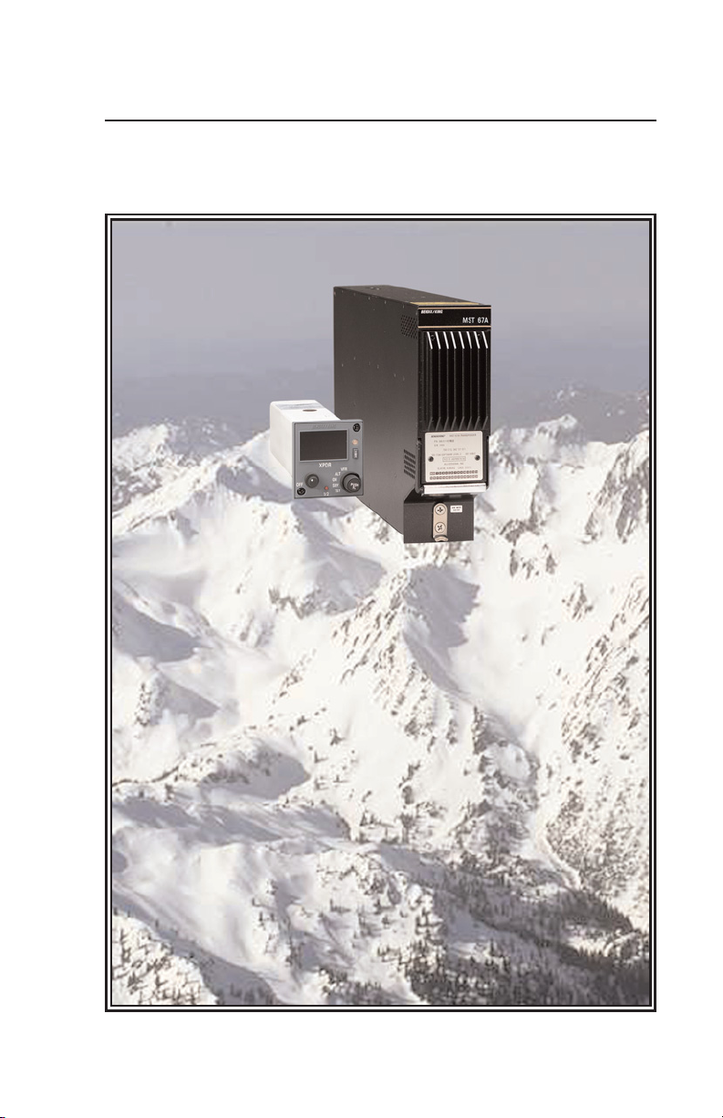
MST 67A
Pilot’s Guide
Honeywell
Mode S Transponder
Effective Date 8/04 006-18301-0000 Rev 1
Page 2

The information contained in this manual is for reference use only. If
any information contained herein conflicts with similar information
contained in the Airplane Flight Manual Supplement, the information in
the Airplane Flight Manual Supplement shall take precedence.
WARNING
The enclosed technical data is eligible for export under Licanse Designation
NLR and is to be used solely by the individual/organization to whom it is
addressed. Diversion contrary to U.S. law is prohibited.
COPYRIGHT NOTICE
Copyright © 2004 Honeywell International Inc.
All rights reserved.
Reproduction of this publication or any portion thereof by any means without
the express written permission of Honeywell International Inc. is prohibited.
For further information contact the Manager, Technical Publications;
Honeywell; One Technology Center; 23500 West 105th Street; Olathe,
Kansas 66061. Telephone: (913) 712-0400.
Page 3

Revision History and Instructions
Manual MST 67A Pilot’s Guide
Revision 1, August 2004
Part Number 006-18301-0000
This revision deletes the RMU 556 from page 2.
R-1
Page 4

Revision History and Instructions
Manual MST 67A Pilot’s Guide
Revision 0, July 2004
Part Number 006-18301-0000
This is the original version of this publication.
R-2
Page 5

MST 67A Pilot’s Guide
SYSTEM COMPONENTS . . . . . . . . . . . . . . . . . . . . . . . . . . . . . . . . .2
INTRODUCTION . . . . . . . . . . . . . . . . . . . . . . . . . . . . . . . . . . . . . . . . .3
SECTION I: CONTROLS AND DISPLAYS . . . . . . . . . . . . . . . . . . . .4
TransponderControl Unit; CTA 81A, B, C & D . . . . . . . . . . . . . . .5
KFS 578A Transponder Control Unit . . . . . . . . . . . . . . . . . . . . .9
PS 578A Transponder Control Unit . . . . . . . . . . . . . . . . . . . . . .11
CD 671C Transponder Control Unit . . . . . . . . . . . . . . . . . . . . .13
PS 550 Transponder Control Unit . . . . . . . . . . . . . . . . . . . . . . .16
SECTION II: SYSTEM CONSIDERATIONS . . . . . . . . . . . . . . . . . .19
Warnings and Limitations . . . . . . . . . . . . . . . . . . . . . . . . . . . . . .19
Cautions . . . . . . . . . . . . . . . . . . . . . . . . . . . . . . . . . . . . . . . . . . .19
Notes . . . . . . . . . . . . . . . . . . . . . . . . . . . . . . . . . . . . . . . . . . . . . .19
SECTION III: APPENDIX . . . . . . . . . . . . . . . . . . . . . . . . . . . . . . . . .20
Functional and Automatic Self Test . . . . . . . . . . . . . . . . . . . . . .20
Glossary of Terms . . . . . . . . . . . . . . . . . . . . . . . . . . . . . . . . . . .21
Table of Contents
1
Effective Date 7/04006-18301-0000 Rev 0
Page 6
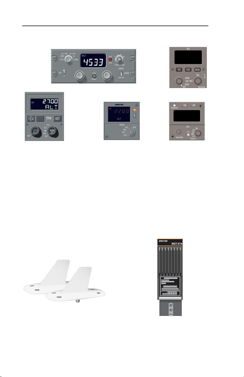
System Components
MODE S CONTROL PANELS
CTA 81A
CD 671C
KFS 578A
REMOTE-MOUNTED HARDWARE
PS 550
PS 578A
DUAL L-BAND OMNI
DIRECTIONAL
ANTENNAS
MST 67A
MODE S
TRANSPONDER
2
006-18301-0000 Rev 1Effective Date 8/04
Page 7

MST 67A Pilot’s Guide
Introduction
INTRODUCTION
Your Honeywell transponder is a radio transmitter and receiver which
operates on radar frequencies. It receives interrogations from ground
radar, airborne radar or TCAS, then returns a coded response of
pulses to the interrogating system. The reply can be any one of 4,096
codes, which differ in the position and number of pulses
transmitted.By replying to ground transmissions, your MST 67A
enables Air Traffic Control (ATC) computers to display aircraft identification, altitude and ground speed on Enroute, Approach or Departure
Control radar screens. When IDENT is selected, your aircraft is positively identified to the Air Traffic Controller. The MST 67A also works
as part of a TCAS II system.
The MST 67A provides you with optimal Mode S transponder performance and offers all the capabilities needed to operate in the evolving world airspace. The MST 67A incorporates the latest technology,
including the Elementary and Enhanced Surveillance functionality
and data link capability with full Level 3 compliance.
The MST 67A features a unique Flight ID function that converts the
transponder Mode S address (for US registered aircraft only) into the
tail number of your aircraft. For most Part 91 operators, this is also
your Flight ID, so it’s automatically stored in the transponder register,
eliminating the need to install and use an additional control head or
FMS. This makes compliance with Elementary Surveillance simple
and convenient.
The MST 67A provides flexibility by allowing you to choose either
diversity or non-diversity installation or to upgrade from non-diversity
to diversity to keep up with changing regulations.
The MST 67A can be controlled by a choice of control heads, and the
operation of the transponder using each is detailed in Section I.
3
Effective Date 7/04006-18301-0000 Rev 0
Page 8
Controls and Displays
SECTION I: CONTROLS AND DISPLAYS
SECTION I DESCRIBES CONTROLS AND DISPLAYS OF
THE MST 67A.
Note: If power is removed from the MST 67A, it will reset in the last
used condition.
4
006-18301-0000 Rev 0Effective Date 7/04
Page 9
MST 67A Pilot’s Guide
Controls and Displays
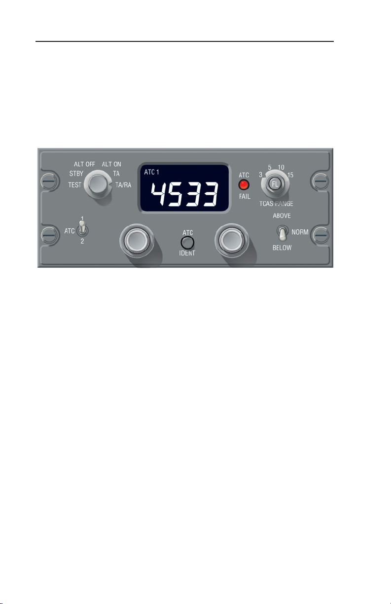
TRANSPONDER CONTROL UNIT; CTA 81A, CTA 81B, CTA 81C, CTA 81D
ATC
FAIL
FAIL
LAMP
5
3
FL
TCAS RANGE
ABOVE
BELOW
10
NORM
15
ABOVE/
BELOW
KNOBS
FUNCTION
SELECTOR
ALT OFF
STBY
TEST
1
ATC
2
ALT ON
TA
TA/RA
DISPLAY
WINDOW
ACT 12 R
ATC
IDENT
TRANSPONDER
SELECTOR
CODE
SELECTOR
KNOBS
IDENT
(PUSHBUTTON)
CODE
SELECTOR
KNOBS
CTA 81A & D Dual Mode S Control Unit, CTA 81C Single Mode
FUNCTION
SELECTOR
ATC 1 ON
STBY
TEST
ALT
TA TA/RA
NO
OFF
ON ATC 2
STBY
TEST
SELECTOR
ACT 12 R
ATC
IDENT
RANGE
ATC
FAIL
FLIGHT LEVEL
(PUSHBUTTON)
5
10
3
15
FL
TCAS RANGE
ABOVE
NORM
BELOW
Mode S Control Unit (CTA 81A shown)
CTA 81B Mode S/ATCRBS Control Unit
CTA 81A, CTA 81B CTA 81C AND CTA 81D CONTROLS AND
DISPLAYS
The CTA 81 ( ) Control Unit is the control for the transponder. The
CTA 81A/D controls two Mode S transponder. The CTA 81B controls
one Mode S transponder and one ATCRBS ARINC 572 transponder. The CTA-81C controls one Mode S transponder.
Note: Controls vary depending on CTA 81 ( ) configuration installed.
Control functions same as typical unit shown.
5
Effective Date 7/04006-18301-0000 Rev 0
Page 10

Controls and Displays
ACT 12 R
1
ATC
2
NO
ALT
OFF
The Display Window displays the 4096 ATC
code selection and whether transponder No. 1
or No. 2 is active. The letter R blinks on the
CTA 81B when indicating the interrogation
reply of ATCRBS transponder only.
ATC 1-2 selects the active transponder. The
other unit is placed in standby.
ALT ON/OFF turns altitude source ON or
OFF.
Concentric knobs select the 4096 ATC code
in the display window.
ATC
FAIL
ATC
IDENT
(Pushbutton)
The ATC FAIL Lamp indicates failure of the
selected transponder.
The ATC IDENT pushbutton is used to initi-
ate the IDENT feature for ATC. The IDENT
function is used at the request of an Air Traffic
Controller, and holds the Ident reply for 18 ± 1
seconds.
6
006-18301-0000 Rev 0Effective Date 7/04
Page 11

MST 67A Pilot’s Guide
FUNCTION SELECTOR CTA 81A/C/D CONTROL UNIT ONLY
(SELECTS OPERATING MODE)
Controls and Displays
ALT OFF
STBY
TEST
Moving the spring loaded knob to TEST position for one second initiates a comprehensive self test lasting approximately eight seconds.
Refer to the Test section in the Appendix for a detailed description of
test functions.
STBY places Mode S transponder and TCAS system in standby.
Use this position during ground operations.
ALT OFF activates Mode S transponder without altitude reporting,
TCAS system in standby.
ALT ON activates Mode S transponder with altitude reporting, TCAS
system in standby.
TA (Traffic Advisory) mode. N/A
TA/RA (Traffic Advisory and Resolution Advisory) mode. N/A
ALT ON
TA
TA/RA
7
Effective Date 7/04006-18301-0000 Rev 0
Page 12

Controls and Displays
FUNCTION SELECTOR CTA 81 B CONTROL UNIT ONLY
(SELECTS OPERATING MODE)
TA TA/RA
ATC 1 ON
ON ATC 2
STBY
TEST
The left ATC 1 TEST position (CCW) tests the Mode S Transponder.
The right ATC 2 TEST position (CW) tests the ATCRBS transponder
only.
Moving the spring loaded knob to either TEST position initiates a self
test in the respective unit. Refer to the Test section in the Appendix
for a detailed description of test function.
Selection of either STBY position places both transponder in standby.
Use standby during ground operations.
ATC 1 ON activates the Mode S transponder.
ON ATC 2 activates the ATCRBS transponder.
TA (Traffic Advisory) mode. N/A
TA/RA (Traffic Advisory and Resolution Advisory) mode. N/A
STBY
TEST
8
006-18301-0000 Rev 0Effective Date 7/04
Page 13

MST 67A Pilot’s Guide
Controls and Displays
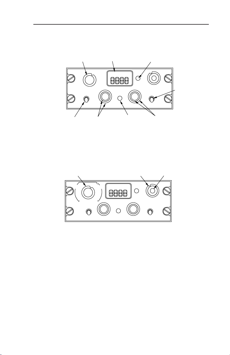
KFS 578A TRANSPONDER CONTROL UNIT
TRANSPONDER 1-2
MODE S
FLIGHT LEVEL
TRANSPONDER MODE
ON/OFF SWITCH
4096 CODE AND FLIGHT LEVEL TEST INDICATOR
ı
2
FL
2200
IDT
ALT
XPDR
ALT VFR
ON
OFF
TRANSPONDER 1-2
SELECT
PUSH
SBY
FL
TST
1/2
FUNCTION
PHOTOCELL
I
IDENT BUTTON
D
T
IDENT
4096 SQUAWK CODE SELECT
PUSH-ADVANCE CURSOR
FL-PUSH AND HOLD
SELECT
KFS 578A Single or Dual Mode S Control Unit (Dual Unit shown).
KFS 578A CONTROLS AND DISPLAYS
The KFS 578A Control Unit is the master control for the transponder.
The KFS 578A will also display the selected 4096 ATC code and current mode of operation in the display window. Versions are available to
control one or two transponder. A “Fail” annunciation indicates failure of
the selected transponder, antenna or control data.
Note: If the KFS 578A is interfaced to a MST 67A Mode S transponder
and the MST 67A senses a failure, a failure annunciation will be shown.
A maintenance check should be performed.
2
FL
2200
1/2
(Pushbutton)
D
T
(Pushbutton)
The Display Window Displays ATC code
selection, whether transponder #1 or #2 is
active, transponder mode, transponder ident
and own aircraft flight level (in TEST).
IDTALT
1/2 selects the active transponder. The other
unit is placed in standby.
I
IDT initiates IDENT feature for ATC. The
IDENT function is used at the request of an
Air Traffic Controller, and holds the Ident reply
for 18 ± 1 seconds.
9
Effective Date 7/04006-18301-0000 Rev 0
Page 14

Controls and Displays
KFS 578A FUNCTION SELECTOR & ATC CODE SELECT
ALT VFR
ON
PUSH
SBY
window will display the encoded altitude for four seconds, then the control unit will return to the previously selected mode. (Refer to the Test
section in the Appendix for a detailed description of test functions.)
SBY places the Mode S Transponde in standby. SBY is annunciated on
the display window. Use SBY during ground operations.
ON activates the selected transponder without altitude reporting. ON is
annunciated in the display window.
ALT activates Mode S transponder with altitude reporting.
Selecting VFR for more than 3 seconds changes the ATC code to the
pre-programmed VFR code (Typically 1200). VFR is annunciated in the
display window for the 3 seconds prior to switching the programmed
code. The control unit will return to the mode selected prior to making
the VFR selection.
FL
TST
The outer concentric knob on the right selects the
transponder mode of operation.
Rotating the function knob (CCW) to the TST position initiates a comprehensive self test lasting
approximately eight seconds. All segments of the
display are illuminated for 2 seconds, then the code
The VFR code can be programmed to be any code by the following
technique:
a. Place the function selector to VFR.
b. Select the VFR code as required.
c. Push the Ident (IDT) button, or wait 3 seconds, or rotate the Function
switch to the desired mode.
10
006-18301-0000 Rev 0Effective Date 7/04
Page 15

MST 67A Pilot’s Guide
Controls and Displays
PS 578A TRANSPONDER CONTROL UNIT
PS 578A Single or Dual Mode S Control Unit (Dual Unit shown).
PS 578A CONTROLS AND DISPLAYS
The PS 578A Control Unit is the master control for the transponder.
The PS 578A will also display the selected 4096 ATC code and current
mode of operation in the display window. Versions are available to control one or two transponder. A “Fail” annunciation indicates failure of the
selected transponder, antenna or control data.
Note: If the PS 578A is interfaced to a MST 67A Mode S transponder
and the MST 67A senses a failure, a failure annunciation will be shown.
A maintenance check should be performed.
The Display Window Displays ATC code
selection, Flight ID (FID) selection, whether
transponder #1 or #2 is active, transponder
mode, transponder ident and own aircraft
flight level (in TEST).
1/2 selects the active transponder. The other unit is
placed in standby.
(Pushbutton)
IDT initiates IDENT feature for ATC. The IDENT
function is used at the request of an Air Traffic
(Pushbutton)
Controller, and holds the Ident reply for 18 ± 1
seconds.
11
Effective Date 7/04006-18301-0000 Rev 0
Page 16

Controls and Displays
FID allows entry of an alphanumeric flight identification.
Selecting the right inner pushbutton will cycle through
(Pushbutton)
PS 578A FUNCTION SELECTOR & ATC CODE SELECT
Rotating the function knob (CCW) to the TST position initiates a comprehensive self test lasting approximately eight seconds. All segments
of the display are illuminated for 2 seconds, then the code window will
display the encoded altitude for four seconds, then the control unit will
return to the previously selected mode. (Refer to the Test section in the
Appendix for a detailed description of test functions.)
the eight characters to be changed. Rotating the right
inner knob will change the contents of the selected
(flashing) character.
The inner concentric knob on the left includes an on/off
switch.
Note: All knobs are continuous rotary and do not roll
over or stop.
The outer concentric knob on the right selects the
transponder mode of operation.
SBY places the Mode S Transponde in standby. SBY is annunciated on
the display window. Use SBY during ground operations.
ON activates the selected transponder without altitude reporting. ON is
annunciated in the display window.
ALT activates Mode S transponder with altitude reporting.
Selecting VFR for more than 3 seconds changes the ATC code to the
pre-programmed VFR code (Typically 1200). VFR is annunciated in the
display window for the 3 seconds prior to switching the programmed
code The control unit will return to the mode selected prior to making
the VFR selection.
12
006-18301-0000 Rev 0Effective Date 7/04
Page 17

MST 67A Pilot’s Guide
Controls and Displays
The VFR code can be programmed to be any code by the following
technique:
a. Place the function selector to VFR.
b. Select the VFR code as required.
c. Push the Ident (IDT) button, or wait 3 seconds, or rotate the Function
switch to the desired mode.
CD 671C TRANSPONDER CONTROL UNIT
4096 CODE &FLIGHT LEVEL TEST INDICATION
TRANSPONDER 1-2
IDENT
TRANSPONDER 1-2
SELECT
4096 SQUAWK CODE
SELECT
1
IDT
1 2 IDT
OFF
TPR
VFR
ALT
PUSH
ON
FL
SBY
TST
TRANSPONDER MODE
IDENT BUTTON
FL PUSH AND HOLD
FUNCTION SELECT
CD 671C Single or Dual Mode S Control Unit (Dual Unit shown).
CD 671C CONTROLS AND DISPLAYS
The CD 671C Control Unit is the master control for the transponder.
The CD 671C will also display the selected 4096 ATC code and current mode of operation in the display window. Versions are available
to control one or two transponder. A “Fail” annunciation indicates failure of the selected transponder, antenna or control data.
Note: If the CD 671A is interfaced to a MST 67A Mode S transponder
and the MST 67A senses a failure, a failure annunciation will be shown.
A maintenance check should be performed.
13
Effective Date 7/04006-18301-0000 Rev 0
Page 18

Controls and Displays
The Display Window displays the ATC
1
IDT
All display annunciations are seen during the control unit self-test.
The "R" annunciation is only seen during self-test. "FL" on the control
unit is only displayed during self-test and indicates the transponder's
encoded altitude. Continuous FL mode is selected by activating Ext.
SBY discrete and turning mode knob to “TST”
The 1/2 push button selects No. 1 or No. 2 as the active
1 2
IDT
transponder. The other unit is placed in standby. The
Display Window shows which transponder is the active
source.
The IDT push button initiates the IDENT feature for ATC.
The IDENT function is used at the request of an Air Traffic
Controller, and holds the Ident reply for 18 ± 1 seconds.
The inner concentric knob may include an optional
ON/OFF switch; clockwise is ON.
code selection, whether transponder #1
or #2 is active, transponder mode,
transponder ident and own aircraft flight
level (in TEST)
OFF
CD671A FUNCTION SELECTOR & ATC CODE SELECT
The dual concentric knobs on the right side of the unit are used to
select the ATC code and Transponder mode. The outer concentric
knob selects the transponder mode of operation. The mode is annunciated in the display window.
TST Rotating the outer function knob (CCW) to
the TST position initiates a comprehensive selftest lasting approximately eight seconds. All segments of the display are illuminated for 2 seconds,
then the code window will display the encoded
altitude for four seconds, then the control unit will
return to the previously selected mode.
14
006-18301-0000 Rev 0Effective Date 7/04
ALT
ON
SBY
VFR
PUSH
FL
TST
Page 19

MST 67A Pilot’s Guide
SBY places the Mode S Transponder in standby. SBY is annunciated in the display window. Use standby during ground operations.
ON activates the selected transponder without altitude reporting. ON
is annunciated in the display window.
ALT Activates Mode S transponder with altitude reporting.
VFR Selecting VFR for more than 3 seconds changes the ATC code
to the pre-programmed VFR code (typically 1200). VFR is annunciated in the display window for the 3 seconds before switching to the
programmed code. The control unit will return to the mode selected
prior to making the VFR selection. The VFR code can be programmed to any code by the following technique:
1. Place the function selector to VFR.
2. Select the VFR code as required.
3. Push the Ident (IDT) button, or wait 3 seconds, or rotate the
Function switch to the desired mode.
The inner concentric knob on the right selects the 4096 ATC code .
To select an ATC code, momentarily push this knob to start the left
hand digit in the ATC code flashing, twist the knob to change the
number. Momentarily push the knob again to move the flashing digit
one space to the right and twist the knob to change the digit. Repeat
for the third and fourth digit of the ATC code. The flashing digit will
stop flashing 3 seconds after the last change.
Controls and Displays
15
Effective Date 7/04006-18301-0000 Rev 0
Page 20

Controls and Displays
PS 550 TRANSPONDER CONTROL UNIT
PS 550 Single or Dual Mode S Control Unit (Dual Unit shown).
PS 550 CONTROLS AND DISPLAYS
The PS 550 Control Unit is the master control for the transponder.
The PS 550 will also display the selected 4096 ATC code and current
mode of operation in the display window. Versions are available to
control one or two transponder. A “Fail” annunciation indicates failure
of the selected transponder, antenna or control data.
Note: If the PS 550 is interfaced to a MST 67A Mode S transponder
and the MST 67A senses a failure, a failure annunciation will be shown.
A maintenance check should be performed.
The Display Window displays the ATC
code selection, whether transponder #1
or #2 is active, transponder mode,
transponder ident and own aircraft flight
level (in TEST).
All display annunciations are seen during
the control unit self-test.
The 1/2 push button selects No. 1 or No.
2 as the active transponder. The other
unit is placed in standby. The Display
Window shows which transponder is the
active source.
16
006-18301-0000 Rev 0Effective Date 7/04
Page 21

MST 67A Pilot’s Guide
The TST push button initiates a comprehensive self-test lasting approximately
eight seconds. All segments of the display are illuminated for 2 seconds, then
the code window will display the encoded
altitude for four seconds.
The MODE push button sequentially
selects the ATC, FL mode, FID and ADC.
ATC Mode - Allows entry of the four digit
ATC code.
Honeywell MST 67A configuration: The
right outer knob selects each of the four
positions for entry, and the right inner
knob selects the content.
Collins TDR-94D configuration: The right outer knob enters the first
two digits and the right inner knob enters the last two digits.
FID Mode - Allows entry of the eight digit alphanumeric flight ID code.
The right outer knob selects each of the eight positions for entry, and
the right inner knob selects the alphanumeric character.
Controls and Displays
ADC Mode - Allows selection of the air data computer used.
The ID push button in the center of the Code Selector
knob initiates the IDENT feature for ATC. The IDENT
function is used at the request of an Air Traffic
Controller, and holds the Ident reply for 18 ± 1 seconds.
PS 550 FUNCTION SELECTOR
The dual concentric knobs on the left side
of the unit are used to select the
Transponder mode. The outer concentric
knob selects the transponder mode of operation. The mode is annunciated in the display window.
STBY places the Mode S Transponder in standby. SBY is annunci-
ated in the display window. Use standby during ground operations.
17
Effective Date 7/04006-18301-0000 Rev 0
Page 22

Controls and Displays
ALT OFF activates the selected transponder without altitude reporting. ON is annunciated in the display window.
XPDR Activates Mode S transponder with altitude reporting.
18
006-18301-0000 Rev 0Effective Date 7/04
Page 23

MST 67A Pilot’s Guide
System Considerations
SECTION II: SYSTEM CONSIDERATIONS
SECTION II EXPLAINS CONSIDERATIONS OF THE SYSTEM; WARNINGS AND LIMITATION, CAUTIONS AND
NOTES.
WARNINGS AND LIMITATIONS
Refer to the Aircraft Flight Manual for the specific operational features
of the transponder installation.
CAUTIONS
None
NOTES
The MST 67A requires the availability of a suitable encoding altimeter
providing altitude input in order to report altitude.
Some enhanced functionality of the MST 67A is configured at the airplane level and is not configurable by the pilot. Refer to the MST 67A
Installation Manual and the Aircraft Flight Manual for details.
19
Effective Date 7/04006-18301-0000 Rev 0
Page 24

Appendix
SECTION III: APPENDIX
THE APPENDIX INCLUDES THE TEST FUNCTION, A
GLOSSARY OF TERMS AND RECOMMENDATIONS FOR
POST FLIGHT REPORTS.
FUNCTIONAL AND AUTOMATIC SELF TEST
The Mode S transponder Functional Test determines the operational
status of the entire system. The test is initiated by rotating the function selector knob on the Transponder Control Panel to the TEST
position.
Thereafter, the test continues automatically for a period of approximately eight seconds. During the test the transponder function is
inhibited. When the knob is held for longer than eight seconds the
system remains in test until it is released.
CTA 81B CLOCKWISE TEST POSITION
The CTA 81B function selector is moved to the right hand test position (switch fully clockwise) to test the ATCRBS transponder. During
the test, segments of the Transponder Control Unit display window
and the ATC Fail lamp illuminate.
POST FLIGHT REPORTS
If a failure of the system has occurred, give Maintenance as much
specific information about the problem as possible. Avoid phrases
such as “Transponder Inop.”
Provide information in terms of fault lights lit, audio announcements,
test pattern discrepancies and screen annunciations that indicate
which unit was observed to have failed.
20
006-18301-0000 Rev 0Effective Date 7/04
Page 25

MST 67A Pilot’s Guide
Appendix
GLOSSARY OF TERMS
ABBREVIATIONS AND DEFINITIONS
AFMS Airplane Flight Manual Supplement
AGL Above Ground Level
ATC Air Traffic Control. A federally operated
ground based system that manages aircraft
traffic flow.
ATCRBS ATC Radar Beacon System. A ground
based secondary radar and airborne
transponder system used to monitor traffic.
Absolute Altitude Altitude above Mean Sea Level (MSL). See
Pressure Altitude.
BITE Built-In Test Equipment. A feature that con-
tinuously monitors itself for operational
errors.
FID Flight Identification
IDENT SPI pulse added to Mode A replies as
method for ground to identify transponder.
SPI info bit is set in Mode S and reported in
the Mode S replies.
Indicated Altitude Altitude shown on the altimeter with baro-
metric correction setting set to local sea
level pressure. Used by the crew below
18,000 feet.
LRU Line Replaceable Unit. A self-contained
avionics component that can be replaced in
the field.
21
Effective Date 7/04006-18301-0000 Rev 0
Page 26

Appendix
ABBREVIATIONS AND DEFINITIONS (CONT’D)
Mode A Transponder ATCRBS transponder that replies to ATC
interrogations sending identification code
but without giving altitude data.
Mode C Transponder ATCRBS transponder that replies to ATC
interrogations giving identification code or
encoded altitude data.
Mode S Transponder Transponder that replies to ATC interroga-
tions giving an ATCRBS identification code,
encoded altitude and other data fields
including aircraft discrete address.
Pressure Altitude Indicated altitude when barometric pressure
is set to 29.92” Hg. (1013mb).
Rad Alt Radio Altitude.
Self Test A functional test that determines equipment
status. Self test differs from BITE performance monitoring because it is initiated by
the crew and is not performed continually or
automatically.
22
006-18301-0000 Rev 0Effective Date 7/04
Page 27

Honeywell International Inc.
One Technology Center
23500 West 105th Street
Olathe, Kansas 66061
FAX 913-791-1302
Telephone: (913) 712-0400
Copyright ©2004 Honeywell International Inc.
All rights reserved.
006-18301-0000
Rev 1 8/04
N
 Loading...