

Page 1
411iedSignai
ELECTRONIC AND AVIONICS SYSTEMS
INSTALLATION MANUAL
BENDIX/KING@
KY 196/197
VHF COMMUNICA TIONS
TRANSCEIVERS
MANUAL NUMBER 006-00169-0003
REVISION 3 SEPTEMBER, 1983
Page 2
WARNING
Information subject to the export control laws. This document. which includes
any attachments and exhibits hereto. contains information subject to
International Traffic in Arms Regulation (ITAR) or Export Administration
Regulation (EAR) of 1979. which may not be exported, released or disclosed to
foreign nationals inside or outside the U.S. without first obtaining an export
license. Violators of ITAR or EAR may be subject to a penalty of 10 years
imprisonment and a fine of $1,000.000 under 22 U.S.C. 2778 or Section
2410 of the Export Administration Act or 1979. Include this notIce with any
reproduced portion of this document.
COPYRIGHT NOTICE
01:>1996AlliedSignal, Inc.
Reproduction of this publication or any portion thereof by any means without
the express written permission of AlliedSignal Commercial Avionics Systems is
prohibited. For further information contact the Manager, Technical
Publications, AlliedSignal Commercial Avionics Systems, 400 North Rogers
Road, Olathe, Kansas, 66062. Telephone: (913) 782-0400.
Page 3

p
2.1
2.2
2.3
2.3.1
2.3.2
2.3.3
2.3.4
2.3.5
2.4
"~
3.1
3.1.1
3.1.2
3.1 .3
3.1.4
3.1.5
Figure
2-1
2-2
2-3
2-4
2-5
2-6
2-7
2-8
2-9
2-10
2-11
2-12
2-13
~3-1
3-2
Page
2-4
2-7
2-9
2-11
2-13
2-15
2-17
2-19
2-21
2-23
2-25
OnLy 2-27
O"Ly
2-2~
3-3
~-l.
Paragraph
1.1
1.2
1.3
1.4
1.5
1.6
KING
KY 196/196E/KY 197/197E
VHF COMMUNICATIONS TRANSCEIVER
TABLE OF CONTENTS
SECTION I
GENERAL INFORMATION
Introduction
Equipment Description
Technical Characteristics
Units and Accessories Supplied
Accessories Required, but Not Supplied
License Requirements
SECTION II
INSTALLATION
General
Unpacking and Inspecting Equipment
InstaLLation
Avionics Cooling Requirements For Panel Mounted Equipment
Mounting Rack Installation
Antenna InstalLation
CabLe Harness and Connector AssembLy
KY 196/196E/197/197E InstaLLation
Post InstaLLation Check
SECTION III
OPERATION
Operating Procedure
Turn On
Transmit Indicator
Mod~ of 0peration
Remote Frequency Transfer
Remote Channel Increment
LIST OF ILLUSTRATIONS
MoLex TerminaL and TooLs (3 Sheets)
Radio Removal TooL (KPN 071-6045-00)
KPN 030-0101-02 Connector AssembLy
KY 196/196E/197/197E OutLine and Mounting Drawing
KY 196/196E/197/197E InstaLLation AssembLy Drawing
KY 197/197E Interconnect Diagram with KMA 20 (13.75VDC)
To Provide 4 ohm Speaker OutPut, Ramp HaiLer and Intercom
KY 196/196E Interconnect Diagram with KMA 20 (27.5VDC)
To Provide 4 ohm Speaker OutPut, Ramp HaiLer and Intercom
KY 197/197E Interconnect Diagram with KA 25A (1~.75VDC)
To Provide 4 ohm Speaker Output
KY 196/196E Interconnect Diagram with KA 25A (27.5VDC)
To Provide 4 ohm Speaker Output
KY 197/197E Interconnect Diagram with KA 134 (1~.75VDC)
To Provide 4 ohm Speaker Output, Ramp HaiLer, and Intercom
KY 196/196E Interconnect Diagram with KA 134 (27.5VDC)
To Provide 4 ohm Speaker Output, Ramp HaiLer, and Intercom
KY 196/196E Interconnect to Provide Intercom and Headphone Output
KY 197/197E Interconnect to Provide Intercom and Headphone Output
Frequency Mode
Program Mode/Memory Mode
Rev. 3, September, 1983
IM0035-2
Paqe
1-1
1-1
1-2
1-4
1-4
1-4
2-1
2-1
2-1
2-1
2-1
2-1
2-2
2-3
2-3
3-1
3-1
3-1
3-1
3-3
3-3
Page 4
KY 196
064-1019-00
Non-Glare lens
KY 196E
064-1019-01
Non-Glare lens
KY 196
064-1019-02
Standard lens
KY 196
064-1019-05
Non-Glare lens,
Memory
Channels
KY 196E
064-1019-06
Non-Glare lens,
Memory
Channels
KY 196
064-1019-07
Standard lens,
Memory
Channels
KY 196
064-1019-10
Non-Glare lens,
Memory
Channels,
Remote
Transfer/Inc
KY 196E
064-1019-11
Non-Glare lens,
lIo1emory
Channels,
Remote
Transfer/Inc
KY 196
064-1019-12
Standard lens,
Memory
Channels,
Remote
Transfer/Inc
KY 197
064-1021-00
Non-Glare
lens
KY 197E
064-1021-01
Non-Glare
Lens
KY 197
064-1021-05
Non-Glare
lens,
Memory Channels
KY 197E
064-1021-06
Non-Glare
lens,
Memory
Channels
KY 197
064-1021-10
Non-Glare
lens,
Memory
Channels,
Remote
Transfer/Inc
KY 197E
064-1021-11
Non-Glare
lens,
Memory
Channels,
Remote
Transfer/Inc
1.2
EQUIPMENT
DESCRIPTION
KING
KY 196/196E/KY 197/197E
VHF COMMUNICATIONS TRANSCEIVER
SECTION I
GENERAL INFORMATION
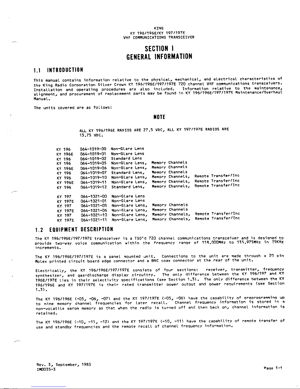
1.1 INTRODUCTION
This manual contains information relative to the physical, mechanical, and electrical characteristics of
the King Radio Corporation Silver Crown KY 196/196E/197/197E 720 channel VHF communications transceivers.
Installation and operating procedures are also included. Information relative to t"e
maintenance,
alignment, and procurement of replacement parts may be found in KY 196/196E/197/197E Maintenance/Overhaul
Manual.
The units covered are as follows:
NOTE
All KY 196/196E RADIOS ARE 27.5 VDC, All KY 197/197E RADIOS ARE
13.75 VDC.
The KY 196/196E/197/197E transceiver is a TSO'd 720 channel communications transceiver and is desiqned to
provide two-w::lYvoice communication within the frequency range of
11~.OOOMHz
to B,).975MHz in ~5KHz
increments.
The KY 196/196E/197/197E is a panel mounted unit. Connections to the unit are made throuqh a 20 pin
Molex printed circuit board edge connector and a BNC coax connector at the rear of t"e unit.
ElectricaLLy, the KY 196/196E/197/197E consists of four sections: receiver, transmitter, frequency
synthesizer, and gas-discharge display circuitry. The only difference between the KY 196/197 and I<Y
196E/197E lies in their selectivity specifications (see Section 1.3). The only difference between the KY
196/196E and KY 197/197E is thei r rated t ransmi tter power out out and power requi r~ments (see Secti on
1.3) .
The KY 196/196E (-aS, -06, -07) and the KY 197/197E (-OS, -06) "ave the capability of oreproqra~minq UP
to nine memory channel frequencies for later recall. Channel frequency information is stored in ::I
non-volatile earom memory so that when the radio is turned off and then back on, channel information is
retained.
The KY 196/196E (-10, -11, -12) and the KY 197/197E (-10, -11) have the capability of remote transfer of
use and standby frequencies and the remote recall of channel frequency information.
Rev. 3, September, 1983
IM0035-3
Paqe 1-1
Page 5
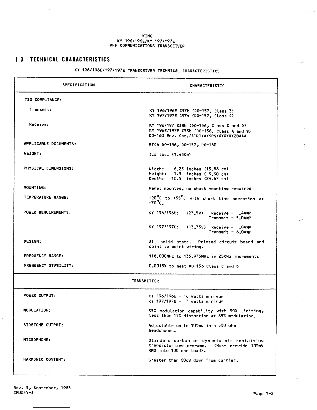
KY 1961196E:
(27.5V)
Receive
-
.4AMP
Transmit
-
5.0AMP
KY 197/197E:
(13.75V)
Receive
-
.~AMP
Transmit
-
6.0AMP
KING
KY 196/196E/KY 197/197E
VHF COMMUNICATIONS TRANSCEIVER
1.3 TECHNICAL CHARACTERISTICS
KY 196/196E/197/197E TRANSCEIVER TECHNICAL CHARACTERISTICS
SPECIFICATION
CHARACTERISTIC
TSO COMPLIANCE:
Transmit:
KY 196/196E C37b (00-157, Class 3)
KY 197/197E C37b (00-157, Class 4)
KY 196/197 C38b (00-156, Class C and D)
KY 196E/197E C38b (DO-156, Class A and B)
00-160 Env. Cat./A1D1/A/KPS/XXXXXXZBAAA
RTCA 00-156, DO-157, 00-160
Receive:
APPLICABLE DOCUMENTS:
WEIGHT:
3.2 lbs. (1.45Kq)
PHYSICAL DIMENSIONS:
Width:
Height:
Depth:
6.~5 inches (15.88 cm)
1.3 inches
(
3.30 cm)
10.5 inches (26.67 cm)
MOUNTING:
TEMPERATURE RANGE:
Panel mounted, no shock mounting required
-200C to +550C with short time operation at
+700C.
POWER REQUIREMENTS:
DESIGN:
All solid state. Printed circuit board and
point to point wirinq.
FREQUENCY RANGE:
118.000MHz to 135.975MHz in 25KHz increments
FREQUENCY STABILITY:
0.0015% to meet 00-156 Class C and D
TRANSMITTER
POWER OUTPUT:
KY 196/196E - 16 watts minimum
KY 197/197E - 7 watts minimum
MODULATION:
85% modulation capabi l ity with 90Y. l imitinq,
less than 15% distortion at 85% modulation.
SIDETONE OUTPUT:
Adjustable up to 1a~mw into 500 ohm
headphones.
MICROPHONE:
Standard carbon or dynamic mic containinq
transistorized pre-amp. (Must provide 10~mV
RMS into 100 ohm load).
HARMONIC CONTENT:
Greater than 60dB down from carrier.
Rev. 3, September, 1983
IM0035-3
Paqe 1-2
Page 6
KING
KY 196/196E/KY 197/197E
VHF COMMUNICATIONS TRANSCEIVER
SPECIFICATION
CHARACTERISTI C
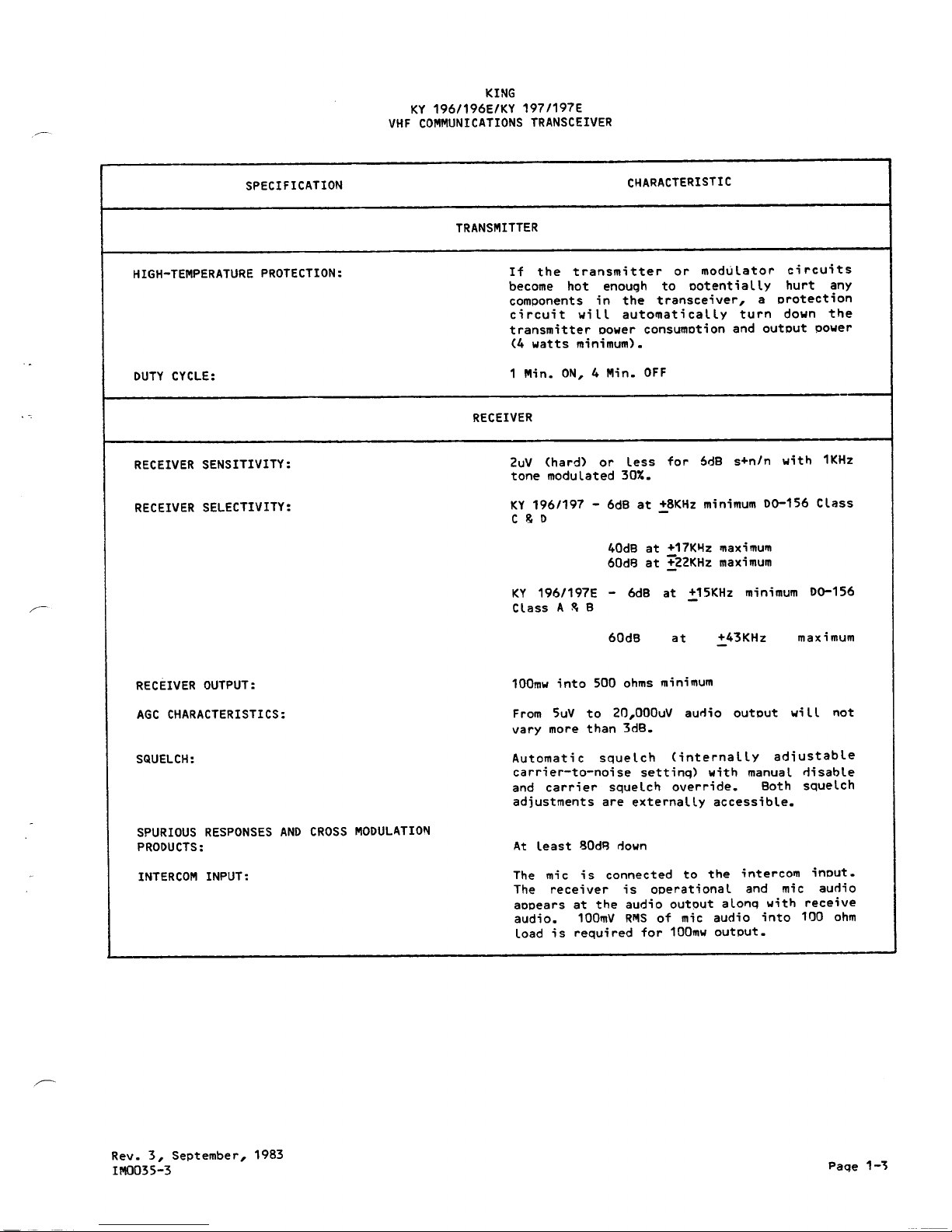
TRANSMITTER
HIGH-TEMPERATURE PROTECTION:
If the transmitter or modulator circuits
become hot enough to ootentially hurt any
components in the transceiver, a protection
ci rcuit wi II automati cally turn down the
transmitter oower consumotion and output power
(4 watts minimum).
DUTY CYCLE:
1 Min. ON, 4 Min. OFF
--
RECEIVER
RECEIVER SENSITIVITY:
2uV (hard) or less for 6dB s+n/n with 1KHz
tone modulated 30%.
RECEIVER SELECTIVITY:
KY 196/197 - 6dB at !8KHz minimum 00-156 Class
C & 0
40dB at +17KHz maximum
60d8 at !22KHZ maximum
KY 196/197E - 6dB at +15KHz minimum 00-156
Class A ~ B
60dB
at
+43KHz
maximum
RECEIVER OUTPUT:
100mw into 500 ohms minimum
AGC CHARACTERISTICS:
From 5uV to 20,000uV aurlio output wi II not
vary more than 3dB.
SQUELCH:
Automatic squelch (internally ad;ustable
carrier-to-noise settinq) with manual rlisable
and carrier squelch override. Both squelch
adjustments are externally accessible.
SPURIOUS RESPONSES AND CROSS MODULATION
PRODUCTS:
At least 80d8 down
INTERCOM INPUT:
The mic is connected to the intercolII input.
The receiver is operational and mic aurlio
appears at the audio output alonq with receive
audio. 100",V RMS of mic audio into 100 ohm
load is required for 100mw output.
Rev. 3, September, 1983
lM0035-3
Paqe 1-~
Page 7
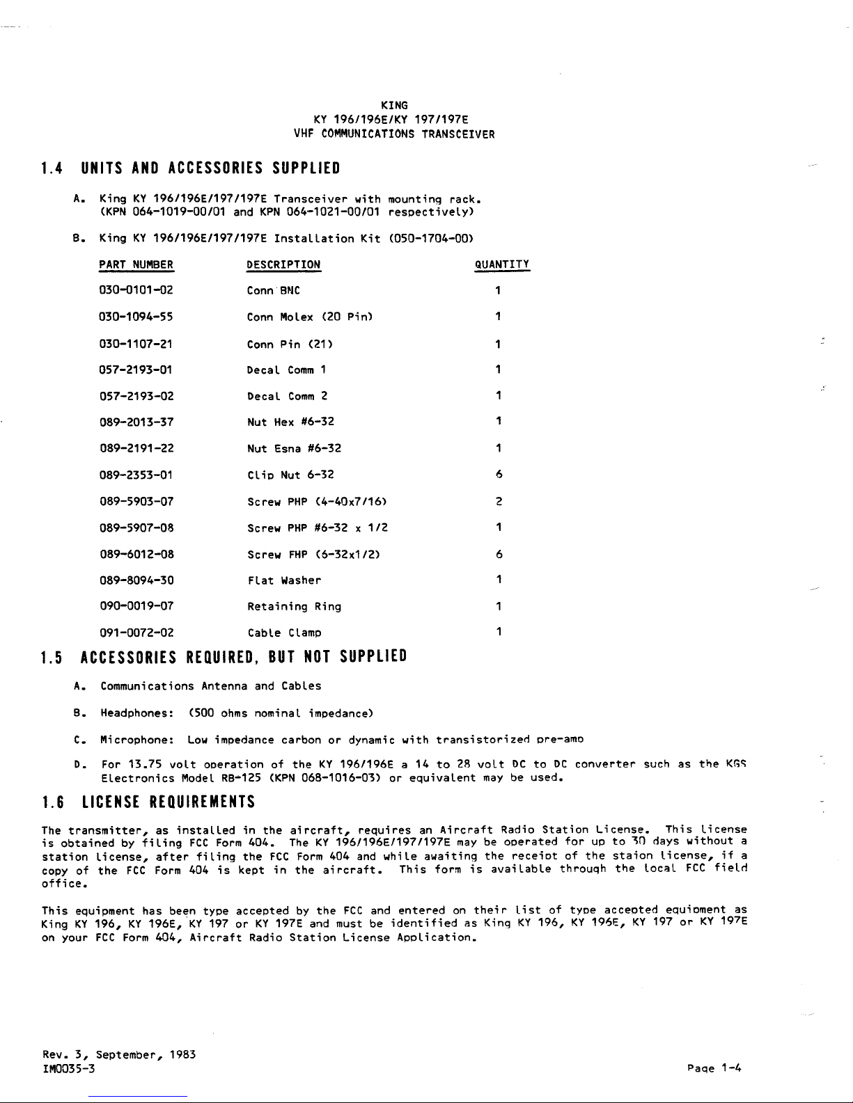
PART NUMBER DESCRIPTION
030-0101-02 Conn BNC
030-1094-55
Conn
Molex
(20
Pin)
030-1107-21
Conn Pin (21)
057-2193-01
Decal
Comm 1
057-2193-02
Decal Comm 2
089-2013-37
Nut
Hex #6-32
089-2191-22
Nut Esna #6-32
089-2353-01
Clip Nut 6-32
089-5903-07 Screw PHP (4-40x7/16)
089-5907-08 Screw PHP
#6-32 x 1/2
089-6012-08 Screw FHP
(6-32x1/2)
089-8094-30
Flat Washer
090-0019-07 Retaining Ring
091-0072-02
Cable Clamp
KING
KY 196/196E/KY 197/197E
VHF ~OMMUNI~ATIONS T~ANS~EIVE~
1.4 UNITS AND ACCESSORIES SUPPLIED
A. King KY 196/196E/197/197E Transceiver with mounting rack.
(KPN 064-1019-00/01 and KPN 064-1021-00/01 respectively)
B. King KY 196/196E/197/197E Installation Kit (050-1704-00)
QUANTITY
1
1
1
1
6
2
1
6
1
1.5
ACCESSORIES REQUIRED, BUT NOT SUPPLIED
A. Communications Antenna and Cables
B. Headphones: (500 ohms nominal impedance)
C. Microphone: Low impedance carbon or dynamic with transistorized pre-amo
D. For 13.75 volt operation of the KY 196/196E a 14 to 28 volt DC to DC converter such as the Kr,~
Electronics Model RB-125 (KPN 068-1016-03) or equivalent may be used.
1.6 LICENSE REQUIREMENTS
The transmitter, as instaLLed in the aircraft, requires an Aircraft Radio Station License. This License
is obtained by fiLing FCC Form 404. The KY 196/196E/197/197E may be operated for up to ~n days without a
station license, after fiLing the FCC Form 404 and while awaiting the receipt of the staion license, if a
copy of the FCC Form 404 is kept in the aircraft. This form is avaiLable throuqh the LocaL FCC field
office.
This equipment has been type accepted by the FCC and entered on their List of type accepted equioment as
King KY 196, KY 196E, 'KY 197 or KY 197E and must be identified as King KY 196, KY 196E, KY 197 or KY 197E
on your FCC Form 404, Aircraft Radio Station License AppLication.
Rev. 3, September, 1983
IM0035-3
Paqe 1-4
Page 8
KHIG
KY 196/196E/KY 197/197E
VHF COMMUNICATIONS TRANSCEIVER
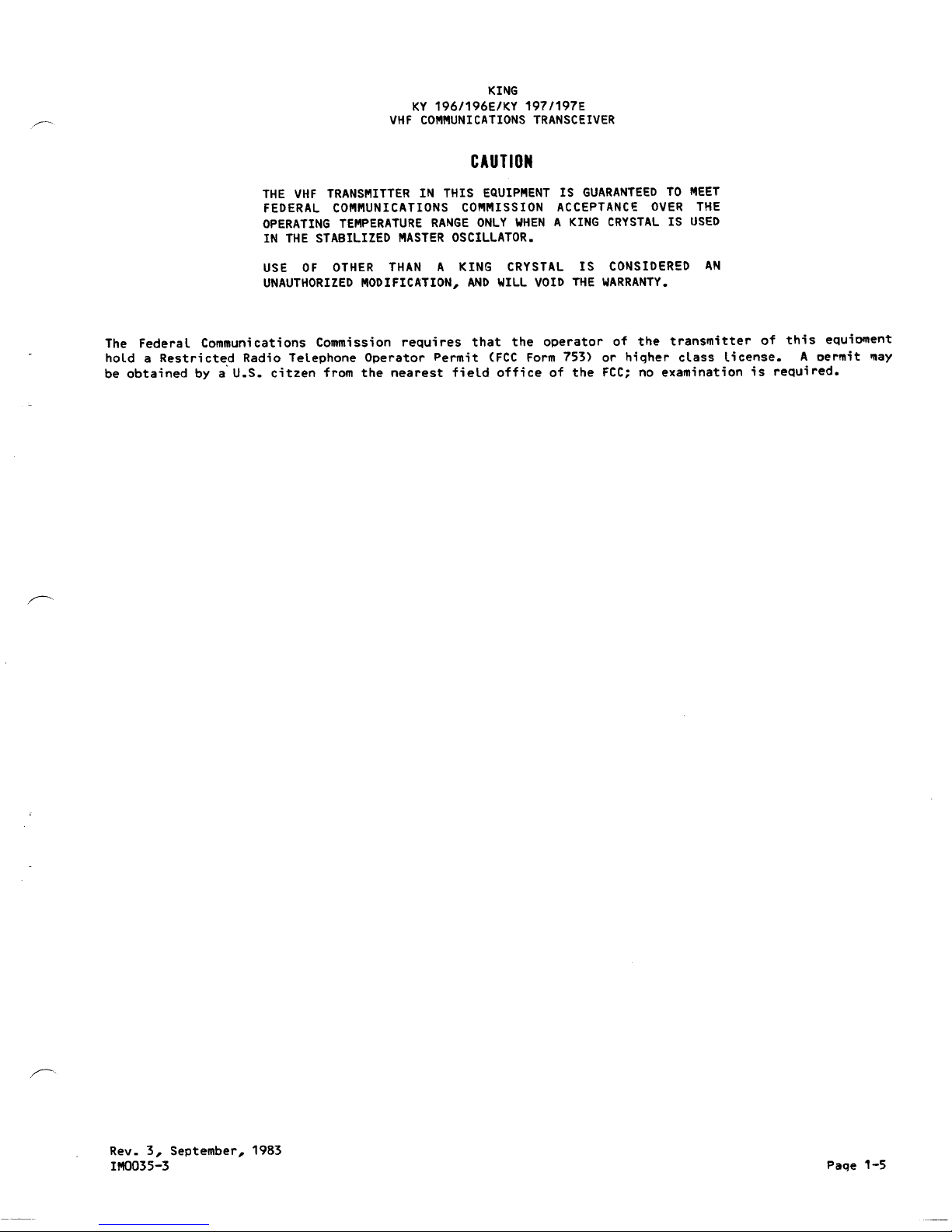
CAUTION
THE VHF TRANSMITTER IN THIS EQUIPMENT IS GUARANTEED TO MEET
FEDERAL COMMUNICATIONS COMMISSION ACCEPTANC~ OVER THE
OPERATING TEMPERATURE RANGE ONLY WHEN A KING CRYSTAL IS USED
IN THE STABILIZED MASTER OSCILLATOR.
USE OF OTHER THAN A KING CRYSTAL IS CONSIDERED AN
UNAUTHORIZED MODIFICATION, AND WILL VOID THE WARRANTY.
The Federal Communications Commission requires that the operator of the transmitter of this equioment
hold a Restricted Radio Telephone Operator Permit (FCC Form 753) or hiqher class license. A oermit may
be obtained by a'U.S. citzen from the nearest field office of the FCC; no examination is required.
Rev. 3, September, 1983
IMO035-3
Paqe 1-5
Page 9
KING
KY 196/196E/KY 197/197E
VHF COMMUNICATIONS TRANSCEIVER
I
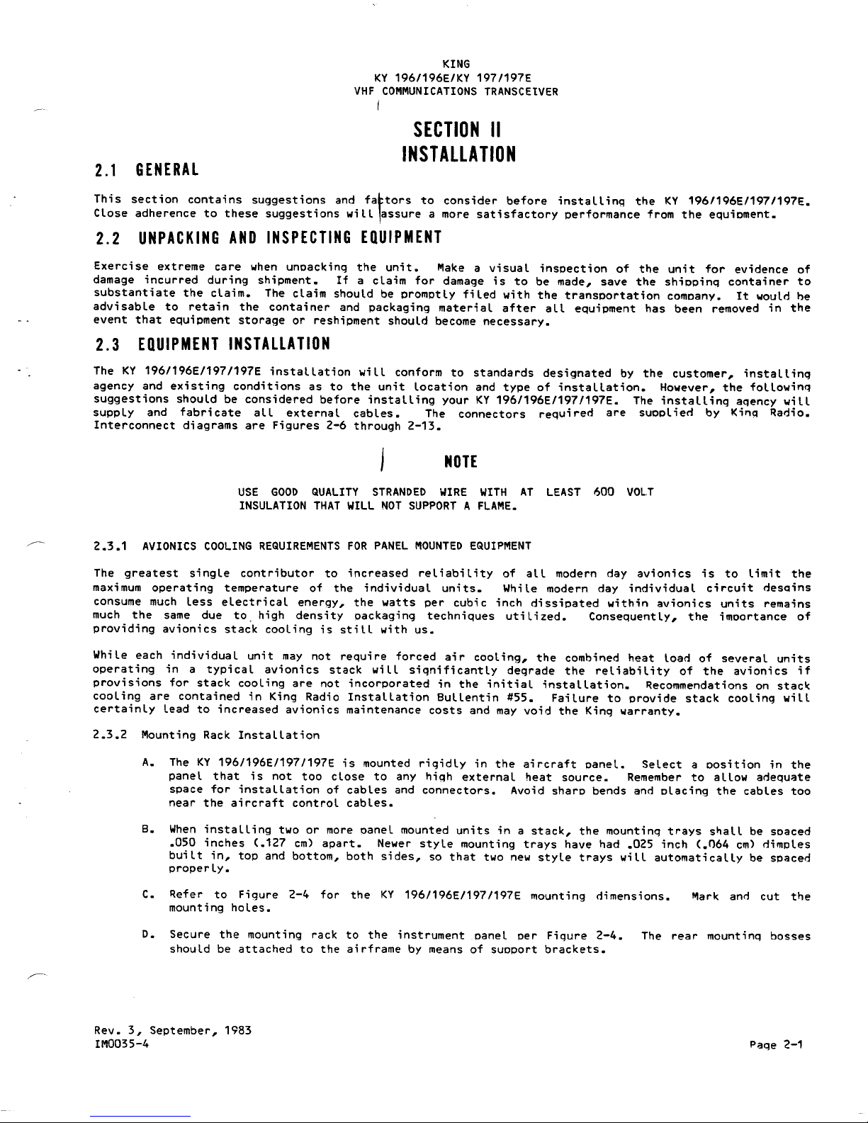
2.1 GENERAL
SECTION II
INSTALLATION
This section contains suggestions and fa~tors to consider before installing the KY 196/196E/197/197E.
Close adherence to these suggestions will 1assure a more satisfactory performance from the equipment.
2.2 UNPACKING AND INSPECTING EQUIPMENT
Exercise extreme care when unpacking the unit. Make a visual inspection of the unit for evidence of
damage incurred during shipment. If a claim for damage is to be made, save the shipping container to
substantiate the claim. The claim should be promptly filed with the transportation company. It would he
advisable to retain the container and packaging material after all equipment has been removed in the
event that equipment storage or reshipment should become necessary.
2.3 EQUIPMENT INSTAlLATION
The KY 196/196E/197/197E installation will conform to standards designated by the customer, installing
agency and existing conditions as to the unit location and type of installation. However, the following
suggestions should be considered before installing your KY 196/196E/197/197E. The installing agency will
supply and fabricate all external cables. The connectors required are supplien by King Radio.
Interconnect diagrams are Figures 2-6 through 2-13.
NOTE
USE GOOD
QUALITY STRANDED WIRE WITH AT LEAST
600
VOL.T
INSULATION THAT
WILL NOT SUPPORT A FLAME.
~
2.3.1 AVIONICS COOLING REQUIREMENTS
FOR PANEL MOUNTED
EQUIPMENT
The greatest single contributor to increased reliability of all modern day avionics is to limit the
maximum operating temperature of the individual units. While modern day individual circuit descdns
consume much less electrical energy, the watts per cubic inch dissipated within avionics units remains
much the same due to. high density packaging techniques utilized. Consequently, the imoortance of
providing avionics stack cooling is still with us.
While each individual unit may not reguire forced air cooling, the combined heat load of several units
operating in a typical avionics stack will significantly degrade the reliability of the avionics if
provisions for stack cooling are not incorporated in the initial installation. Recommendations on stack
cooling are contained in King Radio Installation Bullentin #55. Failure to provide stack cooling will
certainly lead to increased avionics maintenance costs and may void the King warranty.
2.3.2 Mounting Rack Installation
A. The KY 196/196E/197/197E is mounted rigidly in the aircraft panel. Select a position in the
panel that is not too close to any high external heat source. Remember to allow adequate
space for installation of cables and connectors. Avoid sharp bends and placing the cables too
near the aircraft control cables.
B. When installing two or more panel mounted units in a stack, the mounting trays shall be spaced
.050 inches (.127 cm) apart. Newer style mounting trays have had .025 inch <.064 cm) dimples
built in, top and bottom, both sides, so that two new style trays will automatically be spaced
properly.
C. Refer to Figure 2-4 for the KY 196/196E/197/197E mounting dimensions.
mounting holes.
"'ark anI"! cut the
D. Secure the mounting rack to the instrument panel per Figure 2-4. The rear mounting bosses
should be attached to the airframe by means of support brackets.
Rev. 3, September, 1983
IM0035-4
Page 2-1
Page 10
KING
KY 196/196E/KY 197/197E
VHF COMMUNICATIONS TRANSCEIVER
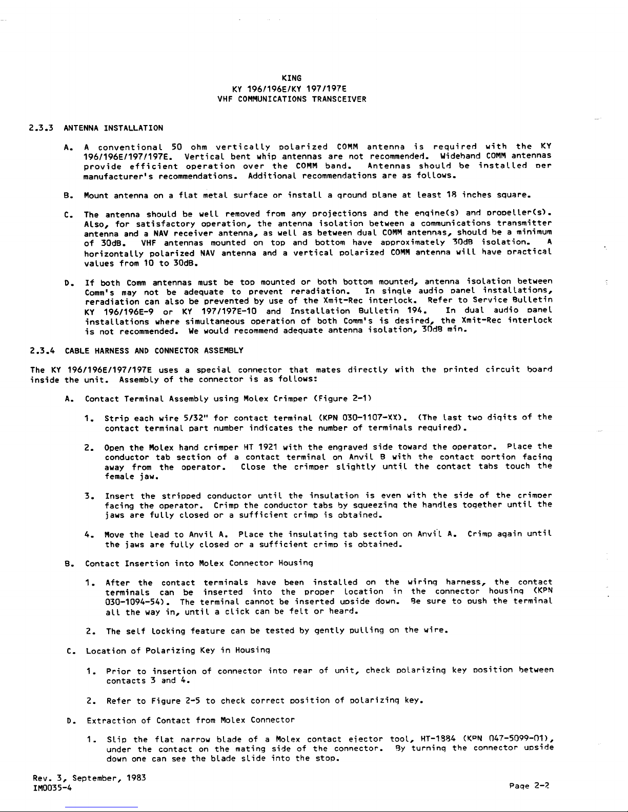
2.3.3
ANTENNA INSTALLATION
A. A conventional 50 ohm vertically polarized
COMM
antenna is requireri with the KY
196/196E/197/197E. Vertical bent whip antennas are not recommenderi. Widehand
COMM
antennas
provide efficient operation over the
COMM
band. Antennas should be installed oer
manufacturer's recommendations. Additional recommendations are as follows.
B. Mount antenna on a flat metal surface or install a qround plane at least 18 inches square.
C. The antenna should be well removed from any projections and the engine(s) anri propeller(s).
Also, for satisfactory operation, the antenna isolation between a communications transmitter
antenna and a NAVreceiver antenna, as well as between dual
COMM
antennas, should be a minimum
of 30dB. VHF antennas mounted on top and bottom have approximately "30dB isolation. A
horizontally polarized NAVantenna and a vertical polarized
COMM
antenna will have practical
values from 10 to 30dB.
D. If both Comm antennas must be top mounted or both bottom mounteri, antenna isolation between
Comm's may not be adequate to prevent reradiation. In single audio panel installations,
reradiation can also be prevented by use of the Xmit-Rec interlock. Refer to Service Bulletin
KY 196/196E-9 or KY 197/197E-10 and Installation Bulletin 194. In dual audio panel
installations where simultaneous operation of both Comm's is desired, the Xmit-Rec interlock
is not recommended. We would recommend adequate antenna isolation, 30dB min.
2.3.4 CABLE HARNESS AND CONNECTOR ASSEMBLY
The KY 196/196E/1971197E uses a speci a l connector that mates di rect ly wi th the printed ci rcui t board
inside the unit. Assembly of the connector is as follows:
A. Contact Terminal Assembly using Molex Crimper (Figure 2-1)
1. Strip each wire 5/32" for contact terminal (KPN 030-1107-XX). (The last two digits of the
contact terminal part number indicates the number of terminals required).
2. Open the Molex hand crimper HT 1921 with the engraved side toward the operator. Place the
conductor tab section of a contact terminal on Anvi l B with the contact oortion facing
away from the operator. Close the crimper slightly untH the contact tabs touch the
female jaw.
3. Insert the stripped conductor until the insulation is even with the side of the crimper
facing the operator. Crimp the conductor tabs by squeezing the handles together until the
jaws are fully closed or a sufficient crimp is obtained.
4. Move the lead to Anvil A. Place the insulating tab section on Anvi-l A. Crimp again until
the jaws are fully closed or a sufficient crimp is obtained.
8. Contact Insertion into Molex Connector Housing
1. After the contact terminals have been installed on the
terminals can be inserted into the proper location in
030-1094-54). The terminal cannot be inserted upside down.
all the way in, until a click can be felt or heard.
wiring harness, the contact
the connector housing (KPN
8e sure to push the terminal
2. The self locking feature can be tested by gently pulling on the wire.
C. Location of Polarizing Key in Housing
1. Prior to insertion of connector into rear of unit, check polarizing key position between
contacts 3 and 4.
2. Refer to Figure 2-5 to check correct position of polarizing key.
D. Extraction of Contact from Molex Connector
1. Slip the flat narrow blade of a Molex contact e;ector tool, HT-1884
(I(PN 047-5099-01),
under the contact on the mating side of the connector. 8y turning the connector upside
down one can see the blade slide into the stoP.
Rev. 3, September, 1983
IM0035-4
Paqe 2-;:!
Page 11
KING
KY 196/196E/KY 197/197E
VHF COMMUNICATIONS TRANSCEIVER
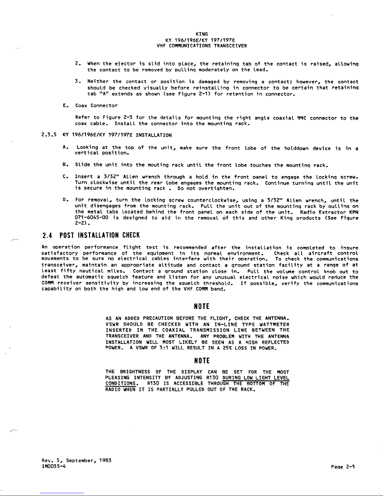
2. When the ejector is sLid into pLace, the retaining tab of the contact is raised, aLLowing
the contact to be removed by puLLing moderateLy on the Lead.
3. Neither the contact or position is damaged by removing a contact; however, the contact
shouLd be checked visuaLLy before reinstaLLing in connector to be certain that retaining
tab "A" extends as shown (see Figure 2-1) for retention in connector.
E. Coax Connector
Refer to Figure 2-3 for the ~etaiLs for mounting the right angLe coaxiaL 9~C connector to the
coax cabLe. InstaLL the connector into the mounting rack.
2.3.5 KY 196/196E/KY 197/197E INSTALLATION
A. Looking at the top of the unit, make sure the front Lobe of the hoLddown device is in a
verticaL position.
B. SLide the unit into the mouting rack untiL the front Lobe touches the mounting rack.
C. Insert a 3/32" ALLen wrench through a hoLd in the front paneL to engage the Locking screw.
Turn clockwise untiL the rear Lobe engages the mounting rack. Continue turning until the unit
is secure in the mounting rack Do not overtighten.
D. For removaL, turn the Locking screw counterclockwise, using a 3/32" ALLen wrench, untiL the
unit disengages from the mounting rack. PulL the unit out of the mounting rack by DulLing on
the metaL tabs Located behind the front paneL on each side of the unit. Radio Extractor KPN
071-6045-00 is designed to aid in the removaL of this and other King products (See Figure
2-2).
2.4
POST INST
AllA
TlON CHECK
An operation performance fLight test is recommended after the instalLation is compLeted to insure
satisfactory performance of the equipment in its normaL environment. Check all aircraft control
movements to be sure no electrical cables interfere with their operation. To check the communications
transceiver, maintain an appropriate aLtitude and contact a ground station faci l ity at a range of at
least fifty nautical miles. Contact a ground station close in. PuLL the voLume control knob out to
defeat the automatic squelch feature and listen for any unusual electrical noise which would renuce the
COMI\1
receiver sensitivity by increasing the squeLch threshold. If possible, verify the communications
capability on both the high and low end of the VHF
COMM
band.
NOTE
AS AN ADDED PRECAUTION BEFORE
THE FLIGHT, CHECK THE
ANTENNA.
VSWR SHOULD
BE
CHECKED
WITH
AN
IN-LINE TYPE WATTMETER
INSERTED IN THE
COAXIAL
TRANSMISSION LINE BETWEEN THE
TRANSCEIVER AND THE ANTENNA. ANY PROBLEM WITH THE AItITENItIA
INSTALLATION WILL MOST LIKELY BE SEEN AS A HIGH REFLECTED
?OWER. A VSWR OF 3:1 WILL RESULT IN A 25~ LOSS IN POWER.
NOTE
THE BRIGHTNESS OF THE DISPLAY CAN BE SET FOR THE MOST
PLEASING INTENSITY BY ADJUSTING R130 DURING LOW LIGHT LEVEL
CONDITIONS. R130 IS ACCESSIBLE THROUGH THE BOTTOM OF THE
RADIO WHEN IT IS PARTIALLY PULLED OUT OF THE RACK.
Rev. 3, September, 1983
I1\10035-4
Page2-~
Page 12

Rev. 2, June, 1982
IM0007-4
KING
KY 196/196E/KY 197/197E
VHF COMMUNICATIONS TRANSCEIVER
INSillAl
;~
,
CONDUCTOR CRIMP
SOLDERLESS
CONTACT TERMINAL
KPN 030-1107-30
-
HAND EJECTOR
KPN 047-5099-01
MOLEX PN HT-1884
FIGURE 2-1 MOLEX TERMINAL AND TOOLS
(Dwg. No. 696-6333-00, R-1)
(Sheet 1 of 3)
Page 2-4
Page 13

JAW TERMINAL WIRE SIZE
INSULATION RANGE
A
030-1107-30
18 to 24 AWG
.110
to
.055
B
030-1107-30
24 to 30AWG
.055
to
.030
KING
KY 196/196E/KY 197/197E
VHF COMMUNICATIONS TRANSCEIVER
Holding the hand
crimpers
as shown, release the crimper's ratchet pawl and open by squeezing tightly
on the handles, and then releasing pressure.
HAND CRIMPER
KPN 071.6041-00
MOLEX
PIN
6115
Close crimpers until ratchet begins to engage. Then insert the terminal into the jaws from the back
side. (See Figures at bottom of page)
For 24 to 30AWG wire, it will be necessary to start the crimp
in jaw A and then complete it in jaw B;
, WIRE STOP
Terminal is in correct position when insulation tabs are flush with outside face of crimp jaws.
FIGURE 2-1 MOLEX TERMINAL AND TOOLS
(Dwg. No. 696-6333-00, R-1)
(Sheet
2 of 3)
Rev. 2, June, 1982
IM0007-4
Page 2-5
Page 14

KING
KY 196/196E/KY 197/197E
VHF COMMUNICATIONS TRANSCEIVER
Once the terminal is in the correct position, close the jaws gently until the terminal is held loosely
in place. Push wire stop down so that it rests snugly behind the contact portion of the terminal.
Strip the wire insulation back 1/8 inch and insert the wire through the insulation tabs into the
conductor tabs until the insulation hits the conductor jaw face or until the conductor touches the
wire stop.
WIRE STOP
Squeeze the handles until the crimp jaws close and the ratchet releases.
Straighten the terminal if necessary, then release the plier grips and remove the crimped terminal.
CRIMPING PRESSURE ADJUSTMENT
If too much or too little pressure is needed to release the crimper's ratchet pawl at the end of
the crimp stroke, the ratchet can be easily adjusted. A spanner wrench provided with the tool can
be used to loosen the lock nut, and rotate the keyed stud clockwise for increased pressure and
counter-clockwise for decreased pressure. Once the desired pressure has been set, the lock nut
must be tightened again. Newer models may have a screwdriver adjustment.
~
KEYED STUD
NUT
(OPPOSITE SIDE)
FIGURE
2-1
MOLEX TERMINAL AND TOOLS
(Dwg. No. 696-6333-00,
R-1)
(Sheet 3 of 3)
Rev. 2, June, 1982
IM0007-4
Page 2-6
Page 15

Rev. 2, June, 1982
IM0007-4
KING
KY 196/196E/KY 197/197E
VHF COMMUNICATIONS TRANSCEIVER
KPN
071-6045-00/
REPLACEMENT HOOKS
047-4796.00,
SHORT HOOKS
047-4796.01,
LONG HOOKS
FIGURE 2-2 RADIO REMOVAL TOOL (KPN 071-6045-00)
(Dwg. No. 155-5395-00, R-O)
Page 2-7
Page 16

KING
KY 196/196E/KY 197/197E
VHF COMMUNICATIONS TRANSCEIVER
COAX:
CUT,STRIP AND SOLDER
AS SHOWN.
AVOID EXCESS SOLDER
ON CENTER CONDUCTOR.
V
~'
~,
'C
Lm~~TALUNG CA,
TACK SOLDER-2 PLACES.
NOTES:
I. AVOID APPLYING EXCESSIVE HEAT TO CONNECTOR BODY.
HEAT SINK SPRING CONTACTS DURING SOLDERING.
FIGURE 2-3 KPN 030-0101-02
CONNECTOR ASSEMBLY
(Dwg. No. 696-6328-00, R-O)
Rev. 2, June, 1982
IM0007-4
12S'ir~
j
LI2S\
SAMEASABOVE.~
"-SOLDER SHIELD OUTSIDE.
SEE NOTE I.
Page 2-9
Page 17

-----
RG-58A1U KPN 026-0015-00
USED ON NAV,COM,DME,XPONDER
AND RADIO TELEPHONE.
RG-124B/U KPN 024-0002-00
DME LOW LOSS AND T5-50
TIMES AA2413PN KPN 024-0013-00
TRANSPONDER LOW LOSS.
IJSE CAUTION WHEN SOLDERING SHIELD,
EXCESS !£AT WILL MELT CENTER
CONDUCTOR INSULATOR.)
Page 18

KING
KY 196/196E/KY 197/197E
VHF COMMUNICATIONS TRANSCEIVER
I-
I
i
9.000
(22.86)
-I
-,
.610
1(1.549)
I
.187 (.47) DIA.
6 PLACES
-
10.176
(25.847)
---------
~
4.200
(10.668)
/
\
\
,
6.312
(16.032)
~--
tjl
i
~.
I (~"
I '
,
: .600
MAX
, (1524)
1.480
(3.759)
NOTES\
I. DIMENSIONS IN
( )
ARE IN CENTIMETERS.
2. WEIGHT\ 3 I LBS. (.1.406
KQ)
3. TOLERANCES FOR PANEL CUTOUTS; ~..~go(:'<6t50)
4 WHEN INSTALLING TWO OR MORE PANEL MOUNTED UNITS IN A STACK, THE MOUNTING TRAYS
SHALL BE SPACED .050 INCHES (.127
CM'>
APART. NEWER STYLE MOUNTING TRAYS HAVE HAD
.025 INCH (D63CM) DIMPLES BUILT IN, TOP AND BOTTOM,BOTH SIDES, SO THAT TWO NEW STYLE
TRAYS WILL AUTOMATICALLY BE SPACED PROPERLY.
5. TO DETERMINE STACK HEIGHT, USE THE HEIGHT DIMENSION FOR A FRONT AIRCRAFT PANEL MOUNT.
FIGURE 2-4 KY 196/196E/197/197E OUTLINE AND MOUNTING DRAWING
(Dwg. No. 155-5309-00, R-4)
Rev. 2, June, 1982
IM0007 -4
Page 2-11
Page 19

LOCKING
SCREW
.-
1.300
(3.30)
L
I
I
I~
6.250
!i5.88}
I
..I
I
'1
1.300 ,
(3.302)
I
LI
I
I
I
~
I
1
CUTOUT DIMENSIONS FOR BEHIND
I
AIRCRAFT PANEL MOUNT
~
I
"j
6.188
!i5.72}
(SEE NOTE 5)
r
1.350
(3.429)
L
14
CUTOUT DIMENSIONS FOR FRONT
AIRCRAFT PANEL MOUNT
6.320
06.052)
.I
I
Page 20

KY 196/19
KING
VHF
COMMUNIC~~~~~S197/197E
TRANSCEIVER
POLARIZING
089-5903-08
047 -46
76
0
-
«REF)
089-5903-07
~
089-2353-01
~."
CLIP NUTS
~
(6 P
L
.6-32
ACES)
FIGURE 2-5 KY
196~196E/197/197E
Dwg. No.
155_5~~~~~~LATION
ASSEMBLY
, R-2)
DRAWING
Rev. 2
IM0007~4June,
1982
Page 2-13
Page 21

--
.--._--
22
030-0101-02
12345678910
FRONT VIEW - CONNECTOR
(LOOKING IN FROM FRONT OF RACK)
Page 22

KPN 030-1094-55
PI961
e
C
4
_.
K
5
Y
6
I
7
9
8
7
9
/
10
1
9
A
7 2
r---
E
3
"*=
D
2
E
F
K
H
Rev. 3, September, 1983
lM0035-4
KING
KY 196/196E/KY 197/197E
VHF COM~UNICATIONS TRANSCEIVER
N IC
-1~IIJrftAnR
INPUT
5OO~OUTPUT(COMM
2)
NAV 2 500-' INPUT
MIC AUDIO lCOMM
2)
.IIIC KEY (COMM 2)
~ 1tST-NC
(SE
NOTE
12)
AUDIO GROUND
--0.....-
MIC GROUND r
--.1-
NIC IItC INTERCOM-SEE NOTE I
(SEE NOTE 12)
13.75V POWER
(SEE NOTE II)
SWITCH ED A IC POWER
AIRCRAFT POWER -"9A-
13.75 VDC
A/C POWER
PowER GROUND
~(SEE NOTE 10)
>eMIT REC INTERLOCKISEE NOTE
9)
PI962
COMM ANTENNA _2
RAIoIP HAIL
OOFF
PIO P201
V.ON
I
-
COMM SPEAKER INPUTL
I
N/C-
,_.
ISlE NOTE
7)
.1._ SOO
~
INPUT :
I
MIC AUDIOl~1I .
MC KEYCCOIItO11-
NC-~ TES'r-
030-2061- 00
PIO P201
XMIT-REC INTERLOCK (SEE 110'II
6
14
16
27
25
19
20
21
22
5
2
3
4
lSEE NO
500~OUTPUTlCOl8l
15
29
28
26
II
, ,
;
WHITE LAMP
- "I
I
8LUE LAMP -
J
:
REMOTE
AM8ER LAMP _
I
OPTION
-
4!l FA SPEAKER lSEE NOTE
8)
NOtH;ynTCHED 5Oo.n. INFur
INST LIGHT DIMMER ~
~
13.75V
I ":' DIMMER
INST LIGHTDIMMER--;-- CONTROL
AICPOWER #20AWG I
RAMP HAILER 8~ ~ a-n1
N~TE
--F. -
AUDIO GROUND
.". ~ MIC GROUND
AIRCRAFT GROUND
""6AWG~ -
NIC Me
""TE~COM-SEE
NOTE I
AIRCRAFT SPEAKER 4
~
~ NOTE (SEE NOTE 12
HF MIC AUDIO ~
2
13.75V POWER
HF MICKEY r---(SEE NOTEII)
HF 500
~
INPUT L SWITCHED A/C POWER
ADF seC-INPUT
r--.
13.75 VDC -9A
-
AIRCRAFT POWER
AI C POWER r--PCVIER GROUND
::::
"n
;!;- (SEE NOTE 10)
MKR~
ANT .".
K
M
A
2
o
SEE
NOTE7
COMII ANTENNA" I
L
I
lL~
FIGURE 2-6 KY 197/197E INTERCONNECT
DIAGRAM
WITH KMA 20 (1~.75VDC)
TO PROVIDE 4 OHM SPEAKER OUTPUT, RAMP HAILER AND INTERCOM
(Dwg. No. 155-1320-00, R-S)
Paqe 2-15
Page 23

_
030-I084-SS
Plt61
H
I
8
C
4
S
6
T
.
9
10
PI1I12
L
K
Y
I
9
7
/
I
9
7
E
#
I
L MIC INTEFtCO"
$ NOT USED. INTERCOMIS PROVUXD 6Y U';ING Ex'!: MODE OF KMA 20 AND
C(JN>I£CTI"G FWIPlWL OIITPV1" TO A RESISTOk LOAD.
2. RAMP HAILER AND AIRCRAFT SPEAKER SHIELDS SHOULD BE CONNECTlD
TO PIN I AT KMA 20.
3. UNLESS NOTED. ALL WIRES 24 AWG MIN IMUM.
4. ALL ANTENNA
COAX
IS RGSB A/U.
5. UNLESS OTHERWISE SPECIFIED.ALL SYSTEM GROUNDS ARE AIRFRAME GROUNDS.
I. POWER BUSS CIRCUIT BREAKERSARETOBE MOUNTED iN THE AIRCRAFT BREAKER
PANEL OR INSTRUMEN"! PANEL SUCH THA"! THEY WILL BE ACCESSIBLE IN FLiGHT
AND SAFE FROM PHYSICAL DAMAGE.
7. THIS INTERCO ECT DRAWING IS FOR, KMA 20', SIN 11233 AND ABOVE. KMA 20',
Sffl 11232 AND BELOW WILL REQUIRE AN EXT Bll LOAD RESIS10R FOR RAMPHAIL
OUTPUT. SEE OoS"!ALL &ULLETIN
_
S6.
8. APPLICABLE TO KMA 20-09.-10.-11.-13 ANo.-I'
ONLY.
9. TX-RX INTERLOCK WIRING NECESSARY WHEN BOTH COMM ANT. ARE 10P MOUNTED, BOTH
COMM ANT. ARE BOTTOM MOUNTED OR IN DUAL COMM INSTALLATIONS IN FABRIC
AIRCRAFT. REFER TO ANTENNA INSTALLAT I ON RECOMMENDATIONS.
10. AI RCRAFT POWER WIRING SHOULD BE
TWO'"
IB AWG TO THE CIRCUIT BREAKER AND
POWER GROUND SHOULD BE
TWO'"
18AWG TO GROUND.
II. SWITCHED A/C POWER. PINS J AND 8 AND 13.7SV POWER PINS F AND 6 MUST BE JUMPERED
TOGETHER
WITH'"
20 AWG MINIMUM.
12. FOR REMOTE FREQUENCY TRANSFER / REMOTE FREQUENCY RECALL (064-102I-1Q/II) OR FIELD
MOD A_ENTARY GROUND AT PINE WILL CAUSE THE RADIO TO INCREMENT TO THE
NEXT FREQUENCY IN MEMORY AND DISPLAY IT IN THE STBY WINDOW. A MOMENTARY
GROUND AT PINT WILL TRANSFER THE USE AND STBY FREQUENCIES. A TWO POSITION
SPRING LOADED ROCKER SWITCH OR TWO SEPARATE MOMENTARY PUSHBUTTON SWITCHES
MAY BE USE 0 AT TH E INSTALLERS OPTION.
Pl961
r;}--AGC TEST/REMOTE INC--<>
OR
~~
l2j--REMOTE XFER
~
~
~
/
/
Page 24

KPN 030-1094-55
PI961
I
8
C
4
_.
K
5
Y
6
r
7
9
8
6
9
I
10
I
9
A
6
2
r--.
E
3
'*
D
2
E
F
H
K
L
Rev. 3, September, '1983
11'10035-4
KING
KY 196/196E/KY 197/197E
VHF COMMUNICATIONS TRANSCEIVER
N/C-'i~MNf~A~rR
INPUT
500 --
OUTPUT tCOMM 2)-
NAV"""
2
500'-'
INPUT
MIC AUDIO (COMM 21
MIC KEY (CONM 2)
SQ,
:EST-
N/C
(SEE NOTE 12)
AUDIO GROUN~
MIC GROUND
-=
N/C MIC INTEFoCOM-SEE NOTE I
(SEE NOTE 121
X:I.~7-
REC INTERLOCK (SEE NOTE
9)
27. 5 VOLT POWER
(SEE NOTE")
SWITCHEL) A/C
PO""EP
...-..
AIRCRAFT PCWER--1A-
27.5 vec
A/C
POWER
powE
R GROUNC
~
(SEE NOTE
10)
Pl962
COMM
ANTENNA #2
PIO P201
7
15
29
28
26
RAMP HAIL
oOFF
030-2061-00
PIC P201
K
M
A
2
o
COMM SPEAKER INPUT-
I
I
N/C
.-. ISEE NOTE 7 I
1
NAV#I500
~
INPUT :
I
I
I
I
WHITE LAMP
- '1
!
8LUE LAMP -
J
r
REMOTE
AM8ER LAMP _
:
OPTION
4n PA SPEAKER (SEE NOTE 81
NON-SWITCHED 50= INPuT
INST LIGHT DIMMER +- 27.5V
INSTLIGHTDIMMER+
N/C
g6~~~~L
A/C POWER 20 AWG I
RAMP HAILER 8- -o-~
~)
n1
NOTE
_ L.l.(,j
2
~
AUDIO GROUND.
I -AIRCRAFT GROUND
**'
16AWG
,,:,,' MIC GROUND
~
~ NIC MlC INTERCOM-SEE NOTE I
10
I
:.,
J.
AIRCRAFT SPEAKER 4
~
~ NOTE (SEE NOTE 12
12 , ,..,HF MICAUD]O
~
2
XMIT-REC INTERLOCKlSEENOTE
24
r--Y
HF MICKEY
27 V POWER
]3
I
. HF 500~ INPUT C:(S~!N8+-1]]]
30
,-'.
ADF5OC~INPUT
SWITCHEDA/C POWER
:- 27.5 voc-'7A- AIRCRAFT
POWER
31
I ".;
DME
500""-
INPUT
AI C POwER POWER GROUND
32 :., HEADPHONE ~.:;
1
~
(SEE NOTE 10)
:,~
~O
:; -=-
COMM ANTENNA# I
"r~
.
-4c
6
14
16
27
500
~
OUTPUT (CCIIIII
MIC AUDIO (CClllllIl
MIC KEY (COMM
I)
25
]9
20
2]
22
5
2
3
NIC-so. TEST
(SEE NOTE
12)
4
SEE
NOTE7
FIGURE 2-7 KY 196/196E INTERCONNECT DIAGRAM WITH
TO PROVIDE 4 OHM SPEAKER OUTPUT, RAMP HAILER
(Dwg. No. 155-1321-00,
R-5)
KMA 20 (27.5VDC)
AND INTERCOM
Page 2-17
Page 25

KPN 030-1014- 55
PIIISI
I
.
C
4
K
5
Y
6
7
I
.
9
9
6
10
/
I
9
A
6
2
E
3
D
#
E
I
~H
~K
~PI962
I. MIC INTERCOM IS NOT USED. INTERCOM IS PROVIIED BY USING EXT. MOOE OF KMA 20 AND
CONNECTING RAMPHAI~ OUTPUT TO A RESISTOR LOAD.
2. RAMP HAILER AND AIRCRAFT SPEAKER SHIELDS SHOULD E1E CONIIIECTED
TO PIN I AT KMA 20.
3. UN~ESS NOTED. A~L WiRES 24 AWG MIN IMUM.
4. AL~ ANTENNA COAX IS RG 58 AIU.
S. UN~ESS OTHERWISE SPECIFIED.ALL SYSTEM GROUNDS ARE AIRFRAME GROUNDS.
6. POWER BUSS CIRCUIT BREAKERS ARE "TOBE MOUNTED IN THE AIRCRAFT BREAKER
PANEL OR INSTRUMENT PANEL SUCH THAT THEY WILL BE ACCESSIBLE IN FLIGHT
AND SAFE FROM PHYSICAL OAMAGE.
7. THIS INTERCONflECT ORAWING IS FOR KMA 20', SIN 11233 AND ABOVE. KMA 20',
511I 11232 AND BELOW WILL REOUIREAN EXT.8n.
LOAD
RESIS10R FOR RAMPHAIL
OUTPUT. SEE
"'STAL~
&U~LETIN
""
56.
8. AP~ICAiLE TO
K"A
2~-09.-10.-11 .-13 AND,-14 ONlY.
9. TX-RX INTERCONNECT WIRING IS NECESSARY WHEN BOTH COMM ANT. ARE TOP MOUNTED. BOTH
COMM ANT. ARE BOTTOM MOUNTED OR IN DUA~ COMM INSTA~TIONS IN FABRIC AIRCRAFT.
REFER "TO
ANTENNA INSTA~LATION RECOMMENDATIONS.
10. AIRCRAFT POWER WIRING SHOU~ 8E
TWO'"
18 AWG
"TO
THE CIRCUIT BREAKER AND POWER
GROUND SHOULD BE
TWO'"
IB AWG TO GROUND.
II. SWITCHED A/C POWER. PINS J AND 8 AND 27.SV POWER PINS HAND 7. MUST BE ~UMPERED
TOGETHER WITH... 20 AWG MINIMUM.
IZ. FOR REMOTE FREQUENCY TRANSFER I REMOTE FREOUENCY RECALL (06~.IDZ HO/ll1l21
OR FIELC MOD I~. A MOMENTARY GROUND
AT PIN E WILL CAUSE THE RADIC
Te'
INCREMENT
TO THE NEX: F~::C:U::NCY !N MErI.CF"cYAND 01SPLLY
IT I~J THE
STay WINDOW. A MOMENTARY
GRCIJND AT F-IN
6 wiLL TRANSFER TI-tE USE toNO STBY. FREOUENCIES. A TWC POSITION
SPRING L.OADED FcOCKER
SWITCH CR TWO SEPARATE MOMENTARY PUSHBUTTON
SWITCHES
MI.Y 9E USED AT THE INSTI.~LERS
OPTION.
J
PI961
~AGC
TESTIREMOTE
6 REMOTE X FER
INC---O
~OR
a
Page 26

KING
KY 196/196E/KY 197/197E
VHF COMMUNICATIONS TRANSCEIVER
COMM I
COMM
2
CQMM.1
KPN 030-1094-55
PI961
KPN 030-2002-00
PIO P251 PIO P251
500n ALOIO OUT
ALOIO GND
C
{Xl
F
Ixi
soon AUCIO OUT
ALOIa GNO
3
I
I
MIC.GNO
~
n,
v
I
MICKEY
""
-~
..
~
.--:.
.
-
.
MIC ALDIO
"
r
' I '-'
(SEE NOTE
8) ,
.
SQ. TEST
_N/C
'-'
I
K
A
2
5
A
W SUMMINGAUDIOIN-
8it SPEAKER
-
MIC.GNO
'.'
40 SPKR~ CAB:N
L~
SPEAKER
E 4!l $PKR
LOAD
-
J 411 SPKR LOAD-
P MIC AUDIO IN-
T
}
(SEE NOTE
8)
~
N/C-SQ.TEST
N 50Dit AUDIO IN ISEE NOTE BI
~
- XIIIT REC INTERLOCK ISEE NOTE
5)
~
AIRFRAM G 0 ~20AWG
A
K
Y
I
9
7
/
I
9
7
E
MIC K£Y
N/C- MIC INTERCOM
MJC AUDIO
MIC KEY
A+ (13.75 OR 215V.DCI "20AWG
TRANSMIT CONTROL
XMlT REC INTERLOCK (SEE NOTE
5)
!SEE NOTE
8)
AlRCRAFTP~ ~1~.75V
I SEE NOTE 61 9AMP AC
P'R
---.
13.75V--0 ':
AC P't\R 9AMP
215V. AIC pOWER
I SEE NOTE6)
r
POWER
GF,OUNO
':"
ISEE NOTE 6
)
6
A
I
L
10
S_I7C>£OA/C POWER
I
(SEE NOTE.7)
13.75V
POWER
[
S"ITCHED AIC POWER
13.75v
powER
(SEE NOTE.7)
PIB62
ANi
RG.58
COM.,"" Arn#'
1
CQMM ANT"#2
NOTES,
I. SELECTOR SWITCH. DOUBLE POLE
-
DOUBLE THROW DPDT
(TO
BE SUPPLIED BY INSTALLER).
2. ALL
WIRES
#24
AWG UNLESS NOTED.
3. TERMINATE
AUDIO
SHIELDS
AT ONE END ONLY
AS SHOWN.
4.PIN
1I',N PARENTHESIS ARE COMMON.
5. TX-RX
INTERLOCK WIRING
15 NECESSAR1'
WHEN BOTH COMM
ANT. ARE TOP MOUNTED. WHEN
BOTH CQMM
A'\IT. ARE BOTTOM
MOUNTED,
OR IN DUAL COMM INSTAllATIONS
IN ~AB~IC
AIRCRAFT. REFER TO ANTENNA INSTAllATION RECOMMENDATIONS.
6. AIRCRAFT POWER WIRING SHOULD 8E TWO
#-
18 AWG TO THE CIRCUIT 8REAKER
AND POWER GROUND SHOULO 8E #-
18 AWG TO GROUND,
7. SWITCHED A/C POWER, PINS J AND 8 AND 13.7SV POWER PINS F AND 6 MUST BE
JUMPERED TOGETHER WITH fItI/I. 20 AWG MINIMUM.
8. FOR REMOTE FREQUENCY TRANSFER I REMOTE FREQUENCY RECALL 1064- 1021-10/11)
OR FIELD MOD 16. A MOMENTARY GROUNO AT
piN
E WILL CAUSE THE RADIO TO INCREMENT
TO THE NEXT FREQUENCY IN MEMORY AND DISPLAY IT IN THE STBY WINDOW. A MOMENTARY
GROUND AT
piN 7 WILL TRANSFER THE USE AND STBY FREQUENCIES. A TWO POSITION
SPRING LOADED ROCKER SWITCH OR TWO SEPARATE MOMENTARY PUSHBUTTON SWITCHES
MAY BE USED AT THE INSTALLERS OPTION.
P!9bl
i~
1
E, AGC TESTIREMOTE INC
~ OR
~REMOTE
XFER
-0 ~
FIGURE 2-8 KY 197/197E INTERCONNECT DIAGRAM WITH KA 25A (13.75VDC)
TO PROVIDE 4 OHM SPEAKER OUTPUT
(owg. No. 155-1325-00,
R-5)
Rev. 3, September, 1983
IMO035-4
COM~ 2
KPN 050-1094-55
pl961
-
.~,NT
R(~-58
E
5
7
K
Y
I
9
7
/
I
9
7
E
o
C
4
6
A
1
L
10
PI962
Paete '--19
Page 27

CCM<
1
KPN 030-1094-SS
Pl961
K
y
I
9
6
/
I
9
6
E
B
2
3
o
KING
KY 196/196E/KY 197/197E
VHF COMMUNICATIONS TRANSCEIVER
C()O< 1
CQIotoO
2
6
K
9
J
S
H
7.
A
1
L
10
PI962
KPN 030-2002-00
PIO P 2S1 PID P2S1
5000 Al.CID OUT
ALOIO
IN)
C
(Xl
SOOII AWIO OJT
-,
ALOIO INJ
SUMMINGAUDIO IN-
8JlSPEAKER
- Mle.GND.
4n SPKR
~
CAB:N
L..f"-..J
SPEAKER
4J1SPKR LOAD-
4J1 SPKR LOAO-
MIC AUDIO IN-
}
(SEE NOTE S I
NIC-SQ.TEST
_
SOO/l. AUDIO IN (SEE NOTE S
XMT REC INTERLOCK (SEE NOTE SI
F .. 0
F
(Xl
w
L
B
I
I
GND.
~
n,
" I
MICKEY
~~~
:0
~ .;.
NIC ALOIO
,.
I '-'
(SEE NOTE
S) I
so. TEST-NIC
'-'
I
+..
..
11
K
A
2
5
A
MIC Kt:Y
A+ U3.7S
OR27.SY.DCI"20_
TRANSMIT CONTROL
N/C- MIC INTERCOM
MIC AUDIO
WIC KEYXMT REC INTERLOCK (SEE NOTE 51
(SEE NOTE
S)
27.5V
AC POWER
:- 0
27. 5V
(SEE NOTE 6 I
7AMP AC
"""
27.SY AC POWER
.,6AWG
[
"ITCHED
27, 5Y.
(SEE NOTE
7)
27. SYPOYIER
,--
POWER GROUND
-=
(SEE NOTE
6)
ANT
RG-sB
ANT
RG-58
CC»4/< ANT# 1
COMM
ANT"
2
NOTES:
I. SELECTOR SWITCH. DOUBLE POLE -DOUBLE THROW DPDT
(TO
BE SUPPLIED BY INSTALLERI.
2. ALL WIRES #24/IING UNLESS NOTED.
3. TERMINATE AlJl)IO SHIELDS AT ONE END ONLY AS SHOWN.
4.PIN
"IN
PARENTHESIS ARE COMMON.
S .TX-RX INTERCONNECT WIRING IS NECESSARY WI£N BOrH COMMANT.
_
TOP IlCU\lTED,
BOTH COW ANT. ARE BOTTOM MOUNTED OR IN DUAL COMM INSTALLATIONS IN
FABRLC AIRCRAFT. REFER TO ANTENNA INSTALLATION RECOMMENDATIONS.
6. AIRCRAFT POWER WIRING SHOULD BE TWO
'*
IS AWG TO THE CIRCUIT BREAKER AND
POWER GROUND SHOULO BE TWO* IS AWG TO GROUND,
7. SWITCHED AlC POWER, PINS J AND SAND 27.SY POWER PINS HAND 7 MUST BE
JUMPER ED TOGETHER
WITH'"
20 AWG MINIMUM.
S. FOR REt<lOTE FREOUENCY TRANSFER I REMOTE FREQUENCY RECALL (064 -
1021 -10/11/12)
OR FIELD MOD IS. A MOMENTARY GROUND AT PIN E WILL CAUSE THE RADIO TO INCREMENT
TO THE NEXT FREQUENCY IN MEMORY AND DISPLAY IT IN THE STBY WINDOW. A MOMENTARY
GROUND AT PIN 6 WILL TRANSFER THE USE AND STBY, FREQUENCIES. A TWO POSITION
SPRING LOADED ROCKER SWITCH OR TWO SEPARATE MOMENTARY PUSHBUTTON SWITCHES
MAY BE USED AT THE INSTALLERS OPTION.
PI961
~AGC TEST/REMOTE INC O
OR
~~
6 REMOTE XFER ~
~
~
FIGURE
2-9 KY
196/196E INTERCONNECT
DIAGRAM
WITH KA 25A (27.5VDC)
TO PROVIDE 4 OHM SPEAKER OUTPUT
(Dwg. No. 155-1322-00, R-5)
Rev. 3, September, 1983
IMO035-4
-
3
E
S
6
F
K
y
I
9
6
/
I
9
6
E
o
C
4
9
J
8
H
7
A
1
L
10
PI962
Paqe 2-21
Page 28

KING
KY 196/196E/KY 197/197E
VHF COMMUNICATIONS TRANSCEIVER
CCIoW NO. 1
KPN 030-1094-55
P1961
CCMM NO.. 2
KPN 0.30-1094- 55
PI961
H
B
PIC P1341
KPN 030-1094-05
PIC PI341 XMIT-REC INTER!.CCK (SEE NOTE
7)
soon AUDIO. CUT
SPEAKER
LOAD
(16M-NIC
MIC AWID
""2
MIC KEY
"2
MIC GNJ
NAV 2 AUDIO-
CABIN SPKR
---8---f'l./1
CABIN
~
SPEAKER
SPEAKERLCADGND!leAWG)
JEE NCTE 10.)
AIRFRAM< GNJ 1
# 184rG I
13.7SV DIMMER CONTROL
NIC':MIC INTERCOM
INSTRLIGHTING:;;;:--l (SEENOTE
2)
:::~: :~'~~~~~~
-: NIC-SQ.TES
INSTR LIGHTING
HEAD PHONES -e-v
K
Y
I
9
7
I
K
Y
I
9
7
E
H
B
INTERLCCK
(SEE NCTE
7)
5Dcn
AlDIC CUT
N/C- SPEAKER LCAD (16.0.1
..
HIC AUUIC
I
MIC
KEY#,
HIC GNO
X MIT -REC
K
Y
I
9
7
/
K
Y
I
9
7
E
, ,
, ,
NAV I
MIC
~MIC
2
(SEE NCTE 10.)
N/C -21.SV
14
MIC INTERCQM- N/C
(SEE NCTE
2)
L- 13. 7512/~:5~LECT
N
15
22
21
2
Ie
AC POIIER
AC POWER
20.
..L
-=(sEE No.TE 10.
16
SQ. TEST-NIC
13.75V
(SEE NCTE 10.)
w
Q
-=
1;~i~:~~~ :
J
8
F
#2
13.75V AC
POWER
r=
r3.75V _
(SEE NCTE
e)
74MP AC POWER
Sr,ITCHED 27.5/13.
75l
(SEE NCTE 91
I>Df
AUDIO.
50.0.11
13.75V PerER
DME AUDIO.50011
MKR AUDIO. 500.11
PO«ER
GROIW---,
DIRECT AUDIO.5Con.
(SEE No.TE
e)
~
DIRECT AUDIO. 50011
DIRECT AUDIO
500.0.
K
9
J
8
~
ITCHED A/C POWER
(SEE NCTE
9)
13.75V P01iER
#1
6
A
1
L
ID
v
13
4
X
M
A
F
6
A
1
L
10.
RAMP
HAILER
'-
\ CR P.A.SPEAKER
SPEAKER \ POWt:R
GRQIJrI()
AU~.MIC AU~lq...,
!ISEE
NCTE
B)
INT/HAIL IN ~
RAMP HAILER
\
CR PA
-:..0 oCN
(SEE NCTE 31
oQFF
COP+1
AN"j" 2 -
ANT
!=lG-58
?1962
P1962
ANT
COMM
ANT # 1
RG-58
tfJTES.
1. 4LL WIRES tfJ. 24AWG UNLESS tfJTED
2. HIC INTERCOM IS NJT USED. INTERCOM IS PROVIDED BY USING RAMP HAILER OR PA SIDETOt£ IN EXT. MCJa;:
CI'
KA 134.
3. IF RAMP HAILER OR PA SIDETCJ<E IS DESIRED FCR INTERCOM, RAMP HAILER OR PA SPEAKER DUTPUT PIN 13. MUST BE
TEAt.UNATED
THRCUGH
A S~ITCH TO A LOAD RESISTCR.
4. P01iER BUSS CIRCUIT BREAKERS ARE TO BE MDLffi'EC IN THE AIRCRAFT BREAKER PAt£L OR INSTRUMENT PANEL SUCH THAT
THEY .ILL BE ACCESSIBLE IN FLIGHT ANJ SAFE FROM PHYSICAL DAMAGE.
5.
"'LESS
OTHERWISE SPECIFIED ALL SYSTEM GRQUNJS ARE AIRFRAME GROUNJS.
6 . PIN !'UMBERS IN PARENTHESES ARE ALL COMMJN.
7. TX
-
RX INTERLCCK WIRING NECESSARY WHEN BCTH CCMM ANT. ARE TOP MOUNTED, BOTH
CC*M
ANT. ARE Bo.TTOM
MOUNTED,CR IN DUAL CCMM INSTALLATICNS IN FABRIC ARCRAFT. REFER TO. ANTENNA INSTALLATICN RECOMMENDATIQNS.
a. AIRCRAFT POWER WIRING SHOULD BE
TWO"","
18AWG TO THE CIRCUIT BREAKER AND POWER
GROUND
SHOULD BE
TWO. ~ IB AWG TO. GROUND.
9. S.WITCHED A/C PCWER, PINS J ANDB 13.75V POWER PINS F AND 6 MUST BE JUMPERED TCGETHER WITH... 2CAWG
MINIMUM.
10.. FCR REMCTE FREQUENCY TRANSFER 1 REMCTE FREQUENCY RECALL (064'-1021-10./11) OR FIELD MOD 16. A Mo.MENTARY
GRCUND AT PIN E WILL CAUSE THE RADIO. TO. INCREMENT TO. THE NEXT FREQUENCY IN MEMo.RY AND DISPLAY IT IN
THE STBY WINDOW. A MOMENTARY GRCUND AT PIN7 WILL TRANSFER THE USE AND STBY FREQUENCIES. A TWO.
POSITICN SPRING LOADED RCCKER SWITCH CR TWO. SEPERATE MOMENTARY PUSHBUTTo.N SWITCHES MAY BE USED
AT THE INSTALLERS OPTICN.
PI961
IEl--AGC TESTIREMCTEINC--<>
7 REMCTE XFER =0
CR
l
FIGURE 2-10 KY 197/197E INTERCONNECT DIAGRAM WITH KA 134 (13.75VDC)
TO PROVIDE 4 OHM SPEAKER OUTPUT, RAMP HAILER AND INTERCOM
(Dwg. No. 155-1323-00, R-5)
Rev. 3, September, 1983
IM0035-4
Paqe 2-23
Page 29

KING
KY 196/196E/KY 197/197E
VHF COMMUNICATIONS TRANSC~IVER
COMM
NO. I
KPN 030-1094-SS
PI96
K
Y
I
9
6
I
K
Y
I
9
6
E
#1
F XMIT REC INTERLOCK
(SEE
NOTE
7)
B 500n ALOIO
(VT
N/C-SPEAKER LOAD (16-)
C
' ,', ~IC Au.JIO~'
4 ~.: MIC KEY. I
3 MIC
Gt.[)
2
NAV1 AUDIO
n
y
,-; MIC ALOIO
"'--'"='--
MIC KEY
. (SEE NOTE 10i
I N/C-
_13.7SV.
~MIC INTERCOM-N/C
(SEE
NOTE
2)
L- 13.1S/21 .~:
.
:LECT
I
PIC PI341
KPN 030-1094-05
PIO PI341 XMIT REC INTERLOCK (SEE NOTE 7
5000 ALOIO OUT
SPEAKER LOAO (161).)-NIC
MIC ALOIO "2
~IC KEY
"2
MIC
GI()
NAV2AUDIO-
CABINSPKR--B--r"1./1 CABIN
SPEAKER
SPEAKERLOADGND(lBAWG)
(SEE NOTE10
AIRFRAIE
GI() I
",lS0lG --:1
N/C
N~-MIC INTERCOM
INSTR
LIGHTING::;:;;:--l
(SEE NOTE
2)
AUX. AUDIO500.n.-NC
-=
NIC-SQ.TEST
AUX.MICKEY-NC
21.SV DI*ER
INSTR LIGHTING
CONTRa-
i
HEADPHONES-€>v
~
(SEE NOTE 10
Z7.5V ---
27.5V AC POWER
AC
!
PMRTAoP
I
smc~:::::::
(SEE NOTE')
21 . SV POftER
V
13
. ~ .-.
RAMP HAILER
4
SPEAKER ','.
OR
P.~A~
LOAO I
\ r (SEE NOTE
8)
AUX.MIC Al.JDI~..., .b
INT/HAILIN~
RAMP
HAI~ER
'-
<3-{A
-'-f
.DN
(SEENOTE3)
GOFF
:CMo1AN7" 2
-
ANT
RG-5e
..
14
IS
22
21
2
18
5
6
AC POI,ER AC POIIER
SQ. TEST -
NIC
21 . sv ...
2OM'G
(SEE NOTE
10)
W
16
20
1
A
1
L
10
Z?::'V AC~.:.
27.5V._
(SEE NOTE
8)
7AMP AC POWER
SI,ITCHED.AlC POWER
-,
'II'
16AWG
(SEE NOTE')
ADF /lL()IO 5Don.
21.5v POI.ER
DME ALOIO SOO.n.
MXR AUDIO SOO.n.
PQl\ER GRO!W--, DIRECT AUDIOSOOt>.
(SEE NOTE
8)
~
DIRECT
DIRECT
M
A
F
Pl962
ANT
NOTES
1. OLL WiRES 'JQ 24A'G
UNLESS NOTEC.
~IC INTERCOM IS NOT USED. !NTERCOM IS PROVIDED BY USING RAI'P HAILER OR PO SIDETQNE IN EXT.
I()QE
~ KA 134.
IF RAMP HOlLER
()R
PA S!DETONE IS DESIREQ FOR INTERCOM. ROMP HAILER OR PA SPEOKFR OUTPUT PIN 13. MUST BE
TERt.lINATED TI-fiOUGH A SP!!TCH
TO A LOAO
RESISTOP.
POWER BUSS CIRCUIT BREOKERS ORE TO BE M'JL~TED IN THE AIRCRAFT BRUKER PANEL OR INSTRUMENT PANE.t. SUCH THAT
iHEY I'\ILL
BE: ACC~SSIBLE I~ FLIGHT Af'l.) SAFE FROM PHYS!CAL DA~GE.
UNLESS OTHERWIS<: SPECIFIED ALL SYSTEM GROUNDS ARE AIRFRAME GROUNDS
PIN NUMBERS IN PARENTHESES ARE ALL COMMCN.
TX-RX INTERCONNEc:T WIRIN. IS NECESSARY WHEN BOTH COMM ANT. ARE TOP MOUNTED, BOTH CDMM ANT. ARE
BOTTOM MOUNTED OR IN DUAL COMM INSTALLATIONS IN FABRIC AIRCRAFT. REFER TO ANTENNA INSTALLATION
RECOMMENDATIONS.
8. AIRCRAFT POWER WIRING SHOULO BE TWO""8AWG TO THE CIRCUIT BREAKER AND POWER GROUND SHOULD
BE
TWO""B
AWG TO GROUND.
9. SWITCHED A/C POWER, PINS J AND BAND 27.SV POWER PINS HAND 7 MUST BE JUMPERED TOGETHER
WITH
'*
20 AWG MINIMUM.
10. FOR REMOTE FREQUENCY TRANSFER/REMOTE FREQUENCY RECALL (064-1021-10/11/12)
OR FIE!..D
,,"Or> 15. A MOMENTARY GROUND AT PIN E WIL!.. CAUSE THE RADIO TO INCREMENT
TO THE NExT FREQUENCY IN MEM0RY AND DISPLA': IT IN THE srBY WINDOW. A MOMENTARY
GROUND
AT PIN 6 WILL TRANSFER THE USE AND ST9Y, FREQUENCIES. A TWO POSITION
SPRING LOADED ROCKER SWITCH OR TWC SEPARATE ~},orI.ENTARY PUSHSUTTQN SWITCHES
Mt.Y BE USED t..: THE INSTALLERS OPTICiJ.
Pl961
W
AGC TEST/REMOTE
6 REMOT~ XFER
INC~
::::;;-<>i
0 R
o
~
FIGURETO2-11 KY 196/196E INTERCONNECT DIAGRAM WITH
PROVIDE 4 OHM SPEAKER OUTPUT, RAMP HAILER,
(Dwg. No. 155-1324-00, R-5)
KA 1~4 (27.5VDC)
A~O INTERCOM
Rev. 3, September, 1983
IMOO35-4
OOMMNO.2
KPN 030-1094-55
Pl961
F
B
E
K
Y
I
9
6
I
K
y
I
9
6
E
D
K
9
J
S
H
#2
1
L
10
Pl962
Page 2-25
Page 30

KPN 030-1094- 55
P 1961
B
2
C
K
D
Y
4
I
3
9 5
6
E
I
F
I
6
9 K
6
9
~E
8
H
7
A
~10
KING
KY 196/196E/KY 197/197E
VHF COMMUNICATIONS TRANSCEIVER
COM
MIC AUDIO
INTERCOM
MIC AUDIO
COMo
INTERCOMot?
I
HEADPHONE I
I
I
I
I
I
I
I
OUT
o
HEADPHONE .JACK
SQ. TEST
-
NIC
(SEE NOTE
8)
XMIT-REC INTER~OCK (SEE NOTE 51
(SEE NOTE
8)
---.
27.5V AIC POWER--
_
27.5vA/C POWER
(SEE NOTE
6)
7AMP
SWITCHEDAIC PO
:=J
ER
(SEE NOTE 71
27.5 V POWER
POWER GND
(SEE NOTE
6)
6. AIRCRAFT POWER WIRING SHOU~ BE-
TWO'"
18 AWG TO THE CIRCUIT BREAKER
AND POWER GROUND SHOU~D BE TWO... 18 AWG TO GROUND.
7. SWITCHED A/C POWER,PINS J AND 8 AND 27.5V POWER PINS HAND 7 MUST BE
JUMPERED TOGETHER
WITH'"
20 AWG MINIMUM.
8. FOR REMOTE FREQUENCY TRANSFER I REMOTE FREQUENCY RECA~~ 1064-1021-1)./11/'2)
DR FIE~D MOD 15 A MOMENTARY GROUND AT PIN E WI~~ CAUSE THE RADIO TO INCREMENT
TO TH:; NEXT FREQUENCY IN MEMORY AND DISPLAY IT IN THE STB't WINDOW. A MOMENTARY
GROUND AT PIN 6 WI~~ TRANSFER THE USE AND STBY. FREQUENCIES. A TWO POSITION
SPRING ~OADED ROCKER SWITCH CR TWO SEPARATE MOMENTARY PUSHBUTTON SWITCHES
MAY BE USED AT THE INSTALL.ERS OPTION.
KPN 030-0101-02
PI962
IT1=
'
E AGC TEST/REMOTE INC---o
6 REMOTE XFER ~
OR
ANT
RG58
NOTES:
I. INTERCOM OPERATION REQUIRES A MIKE WHICH PROVIDES AUDIO OUT WITH THE MIKE
KEY DE-ENERGIZED.
2. A~~ WIRES <II 24 AWG UN~ESS NOTED.
3. TERMINATE SHIE~S AT ONE END ONLY AS SHOWN.
4. A~L GROUNDS ARE AIRFRAME GROUlo[) UNLESS NOTED.
Xlf.IT
_
REC INTERLOCK WIRING NECESSAo<Y
WHE"-'
BOTH COMM ANT. ARE TOP MOUNTcC. BOTH
COMa-. A~ T. ",,~E oOTTO.'" ;~UNTE" OR IN uUAL. COMotiI 1'\I"'T04LL TIO~S IN FAftl:dC
A,R':RAFT CONNECT THIS LINE TO THE MIC KEY UNE OF THE OTHER TRANSCEIVER.
REFER TO ANTENNA INSTALLATION RECOMMENDATIONS.
FIGURE 2-12 KY 196/196E INTERCONNECT TO PROVIDE INTERCOM AND HEADPHONE OUTPUT ONLY
(Dwg. No. 155-1327-00, R-6~
Rev. 3, September, 1983
11110035-4
Paqe 2-27
Page 31

KPN 030-1094-
~~PI961
B
2
C
K
D
Y
4
I
3
9
~7
E
I
H
I
7
9
K
7
9
E
J
B
F
6
A
L
10
KPN 030-0101-02
PI962
KING
KY 196/196E/KY 197/197E
VHF COMMUNICATIONS TRANSCEIVER
COM
MIC AUDIO
INTERCOM
IRC AUDIO
COMo
INTERCOMO
t:?
I
HEADPHONE I OUT
I
I
I
I
I
I
I
MIC
AUDIO
MIC JACK
b
HEADPHONE JACK
SQ. TEST-NlC
(SEE NOTE
8)
X,,",T
-
REC. INTERLOCK (SEE NOTE~)
(SEE NOTE
8)
13.7SV Ale POWER~o--I3."'VA/C POWER
(SEE NOTE
6)
9AMP
SWITCHEDAIC
POWERl
(SEE NOTE 7
)
13.~ V POWER
POWER GND
(SEE NOTE
6)
6. AIRCRAFT POWER WIRING SHOULD BE TWO_18 AWG TO THE CIRCUIT BREAKER AND
POWER GROUND SHOULD BE TWO 18 AWG TO GROUND.
7. SWITCHED AIC POWER. PINS J AND 8 AND 13.7SV POWER PINS F AND 6 MUST BE
JUMPERED TOGETHER
WITH'"
20 AWG MINIMUM.
8. FOR REMOTE FREOUENCY TRANSFER I REMOTE FREOUENCY RECALL (064-1021-1011I) OR FIELD
110O.16. A MOMENTARY GROUND AT PIN E WILL CAUSE THE RADIO TO INCREMENT TO THE
NEXT FREOUENCY IN MEMORY AND DISPLAY IT IN THE STBY WINOOW. A MOMENTARY
GROUND AT PIN 7 WILL TRANSFER THE USE AND STBY FREQUENCIES. A TWO POSITION
SPRING LOADED ROCKER SWITCH OR TWO SEPARATE MOMENTARY PUSHBUTTON SWITCHES
MAY BE USED AT THE INSTALLERS OPTION.
ANT
RG~
Pl961
~t--AGC TEST/REMOTE INC---<>
7 REMOTE XFER ~
OR
NOTES:
I. INTERCOM OPERATION REQUIRES A MIKE WHICH PROVIDES AUDIO OUT WITH THE MIKE
KEY DE-ENERGIZED.
2. ALL
WIRES'"
24 AWG UNLESS NOTED.
3. TERMINATE SHIELDS AT ONE END ONLY AS SHOWN.
4. ALL GROUNDS ARE AIRFRAME GROUND UNLESS NOTED.
5. XMIT- REC INTERLOCK WIRING NECESSARY WIHEN BOTH COMM ANT. ARE TOP MOUNTED,
BOTH COMM ANT. ARE BOTTOM MOUNTED OR IN DUAL COMM INSTALLATIONS IN
FABRIC AIRCRAFT. CONNECT THIS LINE TO THE MIC KEY LINE OF THE OTHER
TRANSCEIVER. REFER TO ANTENNA INSTALLATION RECOMMENDATIONS.
FIGURE 2-13 KY 197/197E INTERCONNECT TO PROVIDE INTERCOM AND HEADPHONE OUTPUT ONLY
(Dwg. No. 155-1326-00, R-6)
Rev. 3, September, 1983
1..0035-4
Paqe 2-28
Page 32

KING
KY 196/196E/KY 197/197E
VHF COMMUNICATIONS TRANSCEIVER
SECTION III
OPERATION
3.1 OPERATING PROCEDURE
3.1 .1 TURN ON
To turn on the unit, rotate the VOL knob clockwise from the OFF position. A non-volatile memory stores
frequency and mode information on power down. When power is activated the USE and STANDBY windows will
display the frequencies displayer::lat power'down and the mode of operation will be the same as at power
down. Frequencies stored in memory channels are also retained.
After activating power, pull the VOL knob out to override the automatic squelch and rotate the VOL knob
to the desired audio level. Push the VOL knob back in to activate the automatic squelch.
NOTE
THE KY 196/197 SHOULD BE TURNED ON ONLY AFTER ENGINE STARTUP.
THIS IS A SIMPLE PRECAUTION WHICH HELPS PROTECT THE SOLID STATE
CIRCUITRY AND EXTENDS THE OPERATING LIFE OF YOUR AVIONICS
EQUIPMENT.
3.1.2 TRANSMIT INDICATOR
During COMM transmission, a lighted "T" will appear between the USE and STANDBY windows to indicate that
the transceiver is in the transmit mode of operation.
3.1.3 MODES OF OPERATION
A. Frequency Mode
In the Frequency Mode of operation frequencies are entered into the STANDBY window of the
display and can then be transferred into the USE window by pressinq the transfer button. The
Frequency Mode may be entered either by entering the Program Mode and entering rlashes (---)
into Channel 0 or alternately may be entered from the Direct Tune Mode.
To select frequencies in this mode, the MHz portion of the frequency displayed in the STANDRY
window may be incremented or decremented in 1 MHz steps by rotatinq the MHz knob either
clockwise or counterclockwise. MHz frequencies will rollover or roll under at each band edqe
(118 or 135 MHz). The KHz portion of the frequency displayed in the STANDRY window may be
incremented or decremented by rotating the 25K/MEM knob either clockwise or counterclockwise.
Frequency selection is in 50 KHz steps when the 25K/MEM is pushed in and is in
'-5
~Hz stees
when the 25K/MEM is pulled out. ~Hz frequencies rollover from 95 to 97 to OQ and roll under-
from 00 to 95 or 97 according to the position of the 25K/MEM knob. Frequencies are
transferred from the
STANDBY
to the USE window and vice versa by depressinq the transfer
button.
B. Program Mode
The Program Mode is used to program frequencies into memory for later recall and to select
either the Frequency Mode or the Channel Mode of operation.
To enter the Program Mode:
1. Depress and hold the transfer button until a flashing Channel number appears in the US~
window of the display (approximately three (3) seconds).
2. Pull the 25K/MEM knob out and rotate it until a "0" appears in the USE window.
3. Push the 25K/MEM knob in and rotate it until "uuu" is displayed in the
STANDRY
window of
the display.
Rev. 3, September, 1983
IM0035-5
Paqe ~-1
Page 33

KING
KY 196/196E/KY 197/197E
VHF COMMUNICATIONS TRANSCEIVER
To program frequencies into memory:
1. Pull the 25K/MEM knob out and rotate it to select a C~annel number (1-9).
2. To enter the frequency, push the 25K/MEM knob back in. The MHz portion of the frequency
may be incremented or decremented in 1 MHz steps with the MHz 'mob. As each band edge
(118 or 135 MHz) is reached, the next transition of the MHz knob will cause dashes (---)
to be displayed. Rollover to the opposite band edge will occur at the next switch
transition. The KHz portion of the frequency may be incremented or decremented in 25 KHz
steps with the 25K/MEM knob.
~. If it is desired to program less than nine
(9) channels, store dashes (---) in the
unwanted channels. In the Channel Mode, channels proqrammed with dashes will be skiooed.
4. When all channels have been programmed, press the transfer button to exit the Proqram
Mode. The radio will now be in the Channel Mode of operation. The radio will
automatically exit the Program Mode and enter the Channel Mode if at any time while in the
Program Mode a twenty (20) second interval lapses with no switch activity.
While in the Program Mode the radio remains tuned to the frequency displayed in the USE window
before this mode was entered.
C. Channel Mode
The Channel Mode is used to recall for use the channel information previously stored in t~e
Program Mode. In order to enter the Channel Mode, the Program Mode must first be entered and
"uuu" must be programmed into Channel O. After these requirements are met, either oressing
the transfer button or allowing twenty (20) seconds to elapse without any switch activity will
cause the radio to enter the Channel Mode.
To recall channel information, pull the 25K/MEM knob out and rotate it until the desired
channel number appears in the USE window. The channel number will be displayed for
approximately two
(2)
seconds after which the USE window will display the active frequency.
The frequency programmed into the channel selected will be displayed in the STANDRY window and
may be transferred to the USE window by pressing the transfer button. The radio will remain
tuned to the last active frequency displayed until the recalled channel information is
transferred to the USE window.
When operating in the Channel Mode, frequencies displayed in the STANDBY window may f}e
temporarily altered with the frequency selectors and transferred to the USE window. MHz and
KHz frequency selection is the same as in the Program Mode. If the orogrammed frequency for a
particular channel is changed in this manner, the original frequency remains in storaqe and
will be displayed the next time that channel is recalled.
D. Direct Tune Mode
The Direct Tune Mode allows direct selection of frequencies displayed in the USE window.
To enter the Direct Tune Mode, the radio must first be turned off. Hold the transfer button
depressed while simultaneously turning t~e radio on, then release the transfer button. Both
windows will display 120.00 and the frequency selectors may be used to enter frequencies
directly into the USE window. MHz and KHz frequency selection is t~e same as in t~e Frequency
Mode.
Entering the Direct Tune Mode automatically programs dashes (---) into Channel O. Therefore,
if the transfer button is depressed after entering this mode, the radio wi II enter t~e
Frequency Mode of operation.
To return to the Channel Mode after operating in the Direct Tune Mode, it is necessary to
first enter the Program Mode and program "uuu" into Channel O. Channel information oreviously
programmed remains stored in memory so it is not necessary to re-enter this information. The
Channel Mode may then be entered by deoressing the transfer button.
Rev. 3, September, 1983
111I0035-5
I)
aqe 3-2
Page 34

KING
KY 196/196E/KY 197/197E
VHF COMMUNICATIONS TRANSCEIVER
3.1.4 REMOTE FREQEUNCY TRANSFER
This feature requires the installation of a remote mounted momentary contact switch. DeDressinq the
remote transfer button will transfer frequencies from the STANDBY win~ow to the USE window and
vice-versa.
3.1.5 REMOTE CHANNEL INCREMENT
This feature requires the installation of a remote mounted momentary contact switch. To use this
feature the radio must fi rst be in the Channel Mode of ooeration. Deoressinq the remote channel
increment button will then cause the radio to increment through the memory channels. Channels will roll
over from 9 to O. Any channel previously Drogrammed with dashes (---) will be skiDDed and will not be
displayed.
ACTIVE
FREQ.
DISPLAY
I
STANDBY
FREQ. DISPLAY
ACTIVE-STANDBY
TRANSFER BUTTON
ON/OFF VOL
PUll-SQ. TEST
MHz KNOB
KHz KNOB
(
KNOB IN-50KHz STEPS
)
KNOB OUT-25KHz STEPS
FIGURE 3-1 FREQUENCY
MODE
(MEMORY
"0" PROGRAMMED TO ---)
Rev. 3, September, 1983
IM0035-5
Page ~-3
Page 35

KING
KY 196/196E/KY 197/197E
VHF COMMUNICATIONS TRANSCEIVER
FIGURE
3-2
PROGRAM MODE/MEMORY
MODE
(MEMORY "0" PROGRAMMED
TO UUU)
Rev. 3, September, 1983
IM0035-5
Page 3-4
 Loading...