

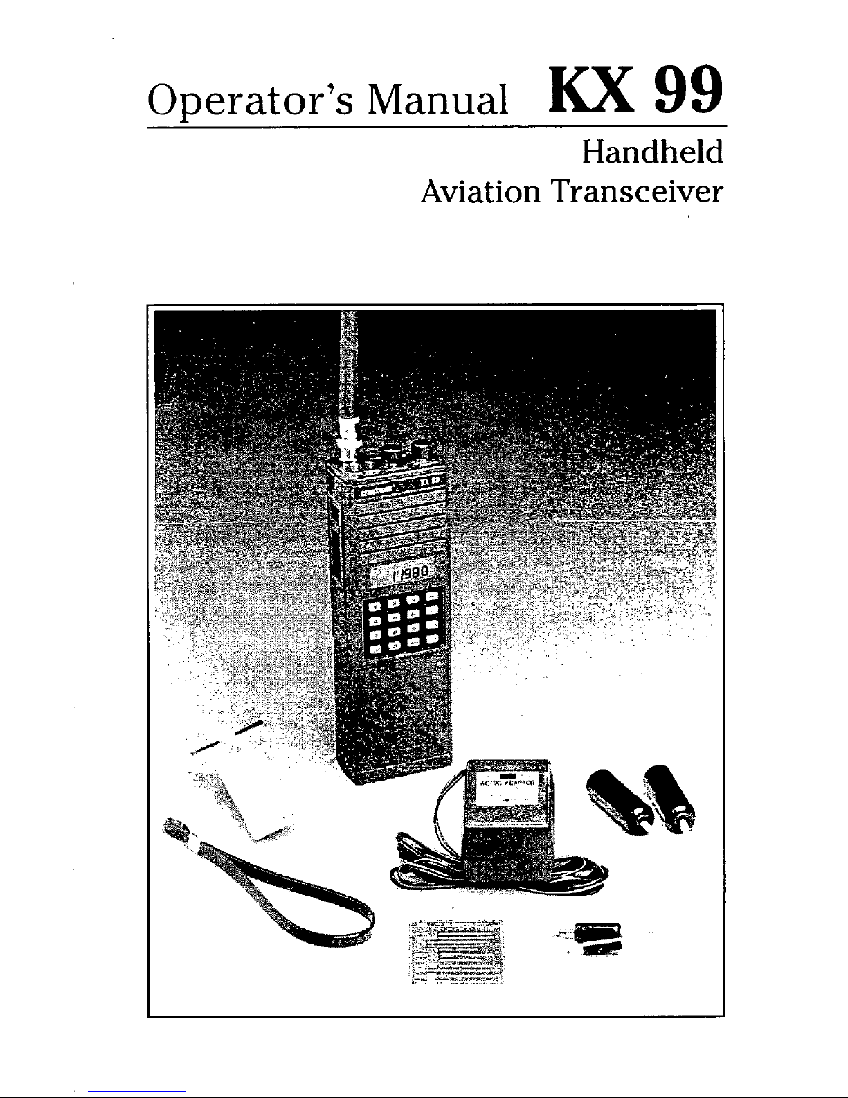
ODerator’s
Manual
Kx
99
Handheld
Aviation Transceiver
Table
of
Contents
Introduction
.........................................................................
2
General Information
Equipment Description
.............................................................
3
License Requirements
..............................................................
3
Antenna Requirements
.............................................................
4
Nickel Cadmium (NiCad) Battery Pack
.....................................
5
Alkaline Battery Pack
................................................................
5
Battery Pack Installation and Removal
.....................................
6
HeadphoneIMicrophone Adapter
..............................................
6
Low Battery Indicator
................................................................
6
KX
99
Controls
Top Controls
............................................................................
8
Front Controls
...........................................................................
9
Side Controls
.........................................................................
10
KX
99
Operation
Basic Communications Operation
.........................................
11
VOR
Navigation Modes
.........................................................
11
Basic NAV CDI Mode
............................................................
12
Course Selection (Changing the OBS Setting)
......................
12
Centering the CDI with a TO Indication
.................................
13
Centering the CDI with a
FR
(From) Indication
.....................
13
Displaying Bearing
to
the
VOR
Station
..................................
14
Displaying Radial from the
VOR
Station
................................
14
Programming Memory Locations
1-9
....................................
15
Recalling Memory Locations
.................................................
16
Duplex Operation
...................................................................
16
Scan Modes
...........................................................................
17
Memory Scan
........................................................................
17
Memory Lockout
....................................................................
18
Frequency Scan Mode
..........................................................
18
Priority Mode
.........................................................................
19
Priority Programming
.............................................................
20
NOAA Weather Radio Channels
...........................................
20
KX
99
Accessories
............................................................
27
In Case Service
Is
Required
......................
Inside Back Cover
Specifications
.......................................................
Back Cover
1
Introduction
This manual contains information
relative
to
the operation and program-
ming
of
the
KX
99
Transceiver.
It
is
best to review the entire manual
before attempting use
of
the
KX
99.
However, persons who require immediate communications capability but
do not have time to study the entire
manual can begin on page
1,
Basic
Communications Operation.
Information on available accessory
items is contained in the
last
section
of
this manual.
2
General Information
This
section contains a basic
description
of
the
KX
99
Transceiver
as well as suggestions and factors to
consider before using the KX
99.
Close adherence
to
these sugges-
tions
will
assure a more satisfactory
performance from the equipment.
Equipment Description
The KX
99
is a 760 channel,
hand-held VHF aircraft communica-
tions transceiver with a
1.5
watt
transmitter output. In addition, the
KX
99
is capable of receiving
200
Nav
channels and all
7
NOAA Weather
Radio Broadcast channels. While
audio is received on all
200
Nav
channels, localizer information is not
processed on the 40 localizer
frequencies. VOR information is
processed and displayed on the liquid
crystal display (LCD) in either a radial,
bearing,
or
Course Deviation Indicator
(CDI) left-right information format. The
KX
99
contains a single receiver.
Therefore,
it
cannot perform the
COMM function and the
NAV
function
simultaneously.
The unit is powered by a selfcontained battery pack. Frequencies
and features are entered via the
keypad on the front of the unit. The
keypad and display may be illuminated for night use. Power On/Off,
volume, squelch sensitivity, keyboard
lockout, and transmitter lockout
controls are located on the top of the
unit. Jacks for headphone and
microphone are also located on the
top of the unit. The flexible antenna
may also be removed
so
the unit may
be used with an external antenna.
License Requirements
If
the KX
99
Transceiver is
to
be
utilized in an aircraft an Aircraft Radio
Station License is required.
If
the
transceiver is
to
be used as a ground
station, then a Ground Station
Authorization is required. Included
with the KX
99
are a FCC Form
404,
Application for Aircraft Radio Station
License and a FCC Form 406,
Application for Ground Station
Authorization in the Aviation Services.
Additional copies may be obtain from
your nearest FCC Field Office.
This equipment has been
accepted by the FCC and entered on
their list of Type Accepted Equipment
as King Radio Corporation Model
KX
99,
(ASY7BL KX
99).
Caution:
The VHF transmitter in this
equipment is guaranteed to meet
FCC acceptance over the operating
femperature range only when a King
crystal is used in the stabilized master
oscillator. Use of other than
a
King
crystal is considered an unauthorized
modification, and will void the
warranty.
3
Antenna Requirements
The flexible antenna that is
included with the KX 99 is very
convenient and may be used for both
communications and navigation
purposes. However a more efficient
antenna may be required for some
applications. For maximum utilization
of the
KX
99 inside an aircraft,
automobile or other metal enclosure,
an external COMM antenna should be
used for communications and an
external NAV antenna should be used
for navigation. An external communi-
cations antenna will noticeably
improve the reception and transmis-
sion
of communication radio signals;
however, it is not recommended for
receiving navigation signals. The use
of
a horizontal type navigation
antenna will improve the reception
and the directional characteristics
of
the navigation signal but it is not
recommended for communications
transmissions from the KX 99. The
BNC type connector, located on the
top
of
the unit, is standard for use on
aircraft radios and antennas
so
little
difficulty should be encountered when
connecting
to
an existing aircraft
communications or navigation antenna.
VOR navigation signals are
received best by a horizontal antenna
while communications signals are
received best by a vertical antenna.
This is a good point to keep in mind
when trying
to
receive weak signals.
When using the flexible antenna in the
cockpit
or
an automobile,
try
to
place
the antenna in the center of a window
which is facing the station you are
trying
to
receive. Remember,
if
the
received station is weak and noisy,
that station is not likely to hear your
transmission. Obtain the best received
signal before attempting to call the
station.
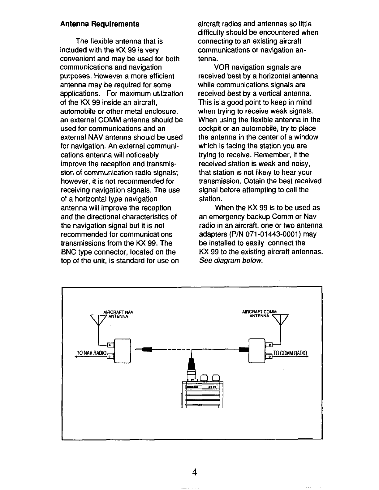
When the KX 99 is
to
be used as
an emergency backup Comm or Nav
radio in an aircraft, one
or two
antenna
adapters
(P/N
071
-01443-0001)
may
be installed
to
easily connect the
KX 99 to the existing aircraft antennas.
See
diagram
below.
4
Nickel Cadmium (NiCad)
Battery Pack
The standard power source
supplied with the
KX
99
is
a
9.6
volt,
720
mA hour, rechargeable nickelcadmium battery pack. The battery
that is shipped with the
KX
99 will not
be fully charged and should be
charged prior
to
use.
If possible, the battery should be
fully discharged before recharging.
This will maintain the maximum useful
charge in the battery and avoid
"memory" problems associated with
this type battery.
A
characteristic of
NiCad batteries is that they do not
hold their charge for long periods of
time such as an alkaline battery does.
Caution:
Do
not store a discharged battery
pack. Battery cell polarity may
reverse making it impossible for the
battery
to
fully recharge.
Do
not store a battery pack where it
might be accidentally shorted. The
current capability is tremendous.
Do
not crush or disassemble a
NiCad battery pack. There are toxic
chemicals inside.
Do
not dispose of the battery pack
in a fire. It may explode.
Do
not exceed the recommended
quick charge current. Use only the
approved chargers.
The
KX
99 comes standard with
a trickle charger capable
of
operating
on either
11
5V or 230V.
To
charge
the battery; plug the charger module
into an appropriate wall outlet and
plug the other end into the connector
marked "CHRG which is located on
top of the
KX
99.
It
takes approxi-
mately
12
hours
to
fully charge the
NiCad battery pack.
Caution:
To avoid possible damage
to
the KX
99
make absolutely certain
that the
7
15V/230V
select switch
located
on
the trickle charger is in the
correct position for the voltage
to
be
used.
The amount of time that the
NiCad battery pack will power the
KX
99 on one charge depends on a
number of factors:
The duty cycle (amount
of
time the
unit is transmitting versus time
receiving
a
signal versus squelched
standby operation). Transmitting
discharges the battery fastest.
The volume level of the received
signal.
The temperature.
A
colder battery
will not last as long.
'
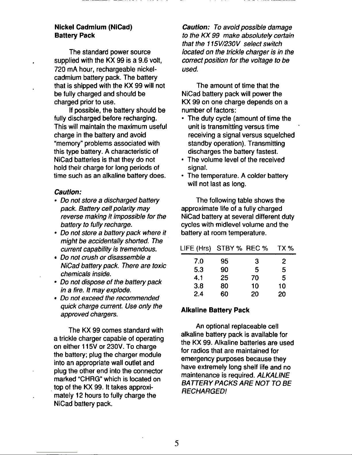
The following table shows the
approximate life of a fully charged
NiCad battery at several different duty
cycles with midlevel volume and the
battery at room temperature.
LIFE (Hrs)
STBY
Yo
REC
Yo
TX
Yo
7.0
95
3
2
5.3 90
5
5
4.1
25
70
5
3.8
80
10
10
2.4
60
20
20
Alkaline Battery Pack
An optional replaceable cell
alkaline battery pack is available for
the
KX
99.
Alkaline batteries are used
for radios that are maintained for
emergency purposes because they
have extremely long shelf life and no
maintenance is required.
ALKALINE
BATTERY PACKS ARE NOT TO
BE
RECHARGED!
5
The alkaline battery pack holds
8
'AA"
size cells. To gain access
to
the
8
cells, first remove the battery pack
from the KX
99
(see below). Next,
with one hand holding the outside of
the battery pack case, use the other
hand
to
press down firmly on the
center hub on the top of the case.
The battery cell holder will slide out
the bottom of the case.
Alkaline battery life will be
approximately the same as that
of
a
NiCad for a
90%
STBY,
5%
REC
and
5%
TX
duty cycle. However, alkaline
batttery life will be considerably less
than a NiCad at higher duty cycles
and considerably greater than a
NiCad at lower duty cycles.
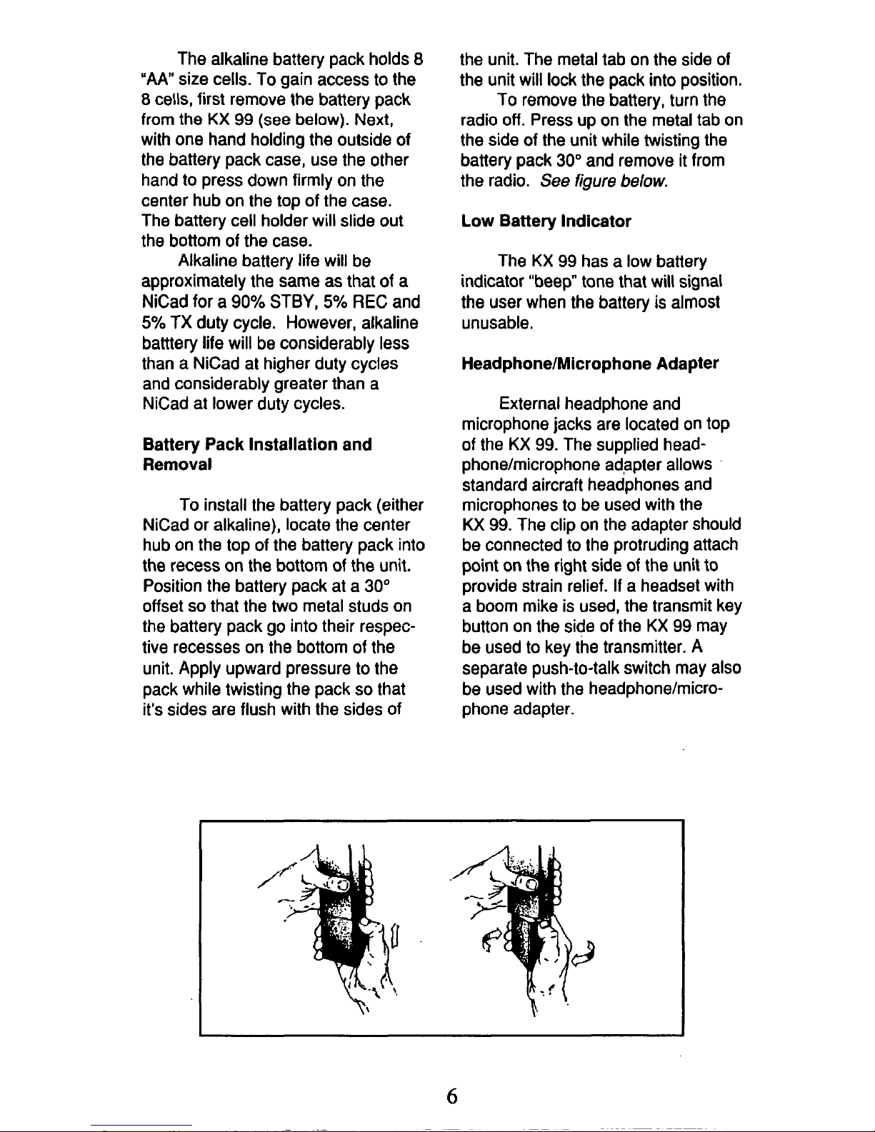
Battery Pack Installation and
Removal
To install the battery pack (either
NiCad or alkaline), locate the center
hub on the top of the battery pack into
the recess on the bottom of the unit.
Position the battery pack at a
30"
offset
so
that the two metal studs on
the battery pack go into their respec-
tive recesses on the bottom
of
the
unit. Apply upward pressure
to
the
pack while twisting the pack
so
that
it's sides are flush with the sides of
the unit. The metal tab on the side of
the unit will lock the pack into position.
To
remove the battery, turn the
radio
off.
Press up on the metal tab on
the side of the unit while twisting the
battery pack
30"
and remove it from
the radio.
See
figure
below.
Low
Battery Indicator
The KX
99
has a low battery
indicator "beep" tone that
will
signal
the user when the battery
is
almost
unusable.
HeadphonelMicrophone Adapter
External headphone and
microphone jacks are located on top
of the
KX
99.
The supplied headphone/microphone adapter allows
standard aircraft headphones and
microphones
to
be used with the
KX
99.
The clip on the adapter should
be connected
to
the protruding attach
point
on
the right side of the unit to
provide strain relief.
If
a headset with
a boom mike is used, the transmit key
button on the side of the
KX
99
may
be used
to
key the transmitter. A
separate push-to-talk switch may also
be used with the headphonelmicrophone adapter.
6
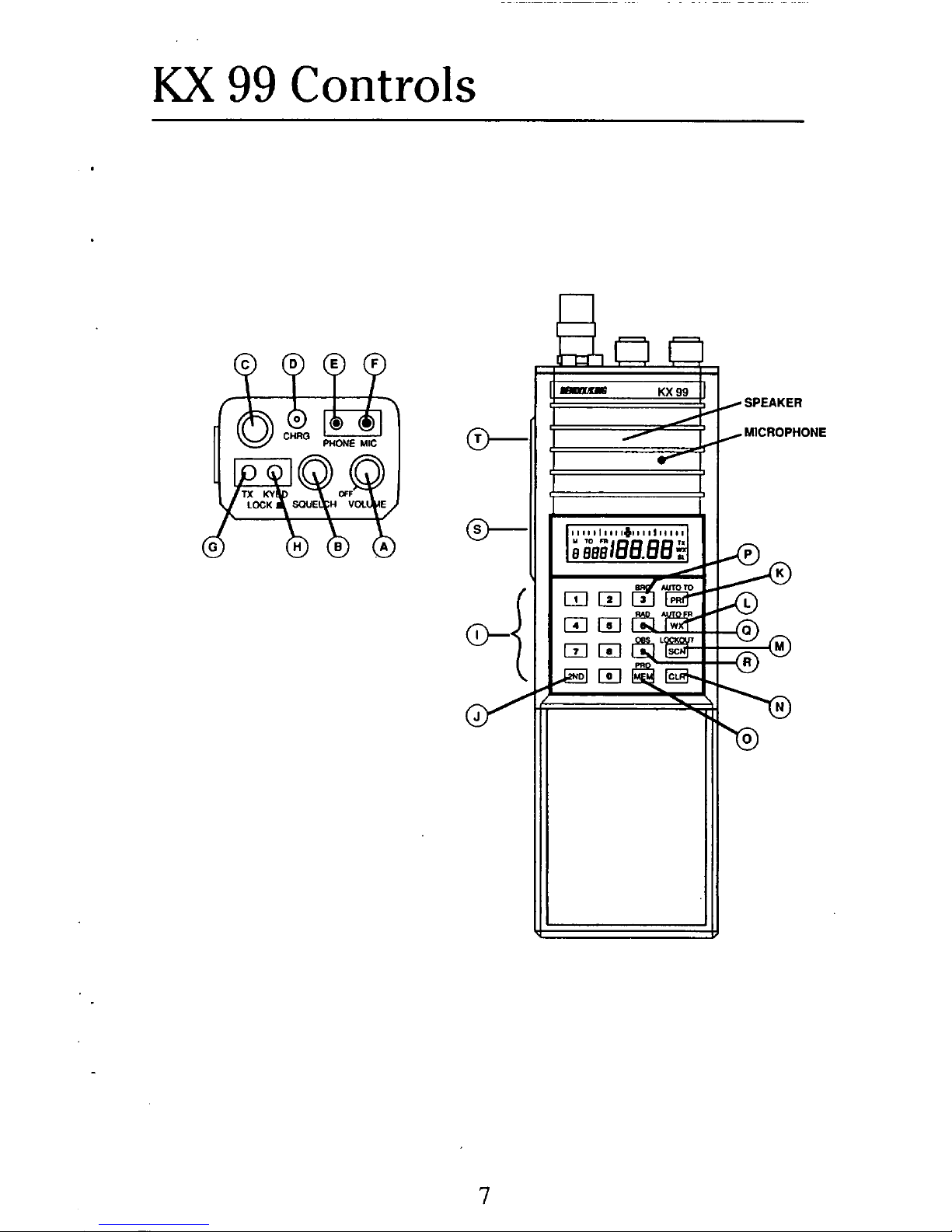
KX
99
Controls
SPEAKER
MICROPHONE
7
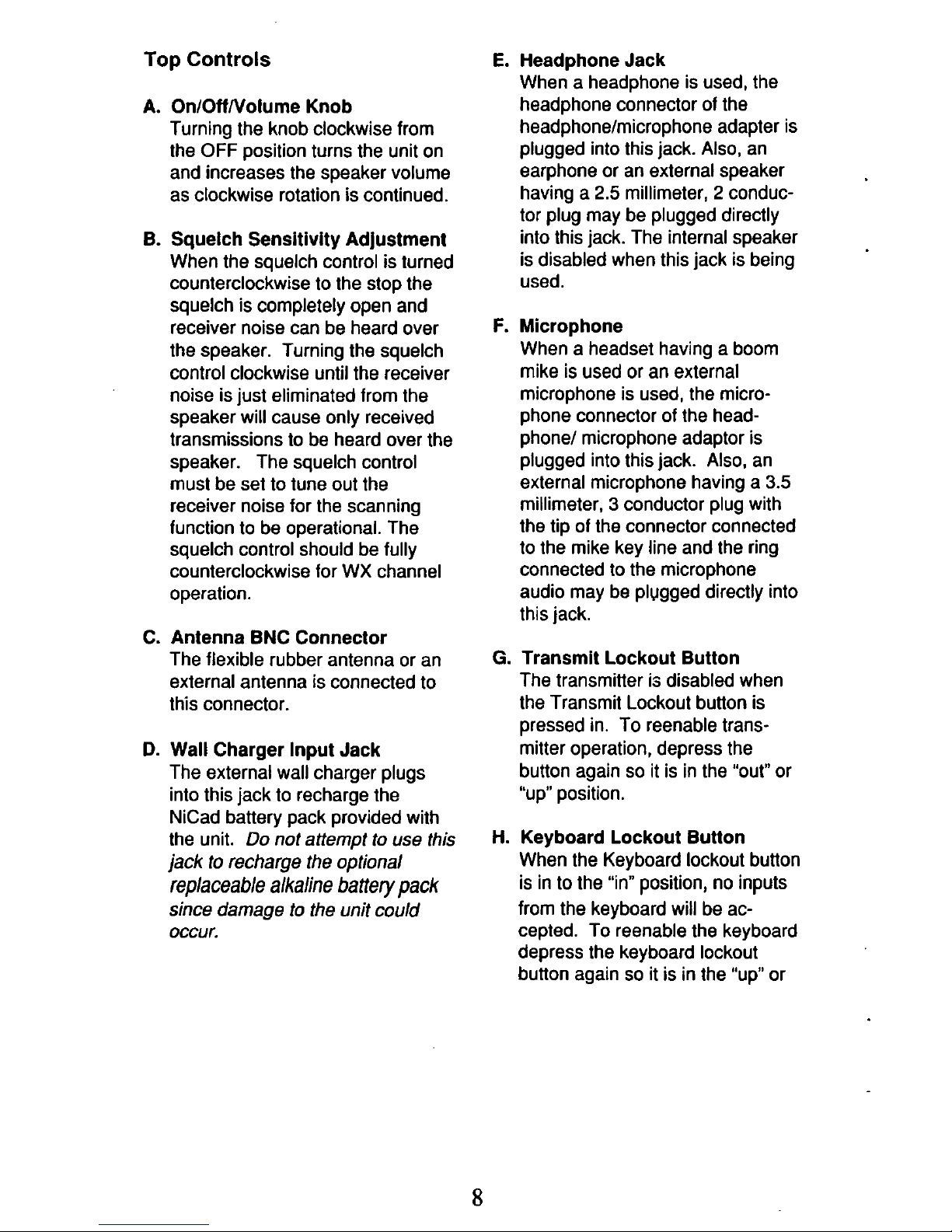
Top
Controls
A.
OnlOffNolume Knob
Turning the knob clockwise from
the
OFF
position turns the unit on
and increases the speaker volume
as clockwise rotation is continued.
B.
Squelch Sensitivity Adjustment
When the squelch control is turned
counterclockwise
to
the stop the
squelch is completely open and
receiver noise can be heard over
the speaker. Turning the squelch
control clockwise until the receiver
noise is just eliminated from the
speaker will cause only received
transmissions
to
be heard over the
speaker. The squelch control
must be set
to
tune out the
receiver noise for the scanning
function
to
be operational. The
squelch control should be fully
counterclockwise for WX channel
operation.
C. Antenna BNC Connector
The flexible rubber antenna or an
external antenna is connected
to
this
connector.
D.
Wall Charger Input Jack
The external wall charger plugs
into this jack
to
recharge the
NiCad battery pack provided with
the unit.
Do
not attempt to use this
jack
to
recharge the optional
replaceable alkaline battery pack
since damage
to
the unit
could
occur.
E.
Headphone Jack
When a headphone is used, the
headphone connector
of
the
headphone/microphone adapter is
plugged into this jack.
Also,
an
earphone or an external speaker
having a
2.5
millimeter, 2 conduc-
tor plug may be plugged directly
into this jack. The internal speaker
is disabled when this jack is being
used.
F.
Microphone
When a headset having a boom
mike is used or an external
microphone is used, the microphone connector
of
the headphone/ microphone adaptor is
plugged into this jack. Also, an
external microphone having a
3.5
millimeter, 3 conductor plug with
the tip
of
the connector connected
to
the mike key line and the ring
connected
to
the microphone
audio may be plugged directly into
this jack.
G.
Transmit Lockout Button
The transmitter is disabled when
the Transmit Lockout button is
pressed in. To reenable transmitter operation, depress the
button again
so
it is in the "out"
or
"up" position.
H. Keyboard Lockout Button
When the Keyboard lockout button
is in
to
the "in" position, no inputs
from the keyboard will be accepted. To reenable the keyboard
depress the keyboard lockout
button again
so
it is in the "up" or
8
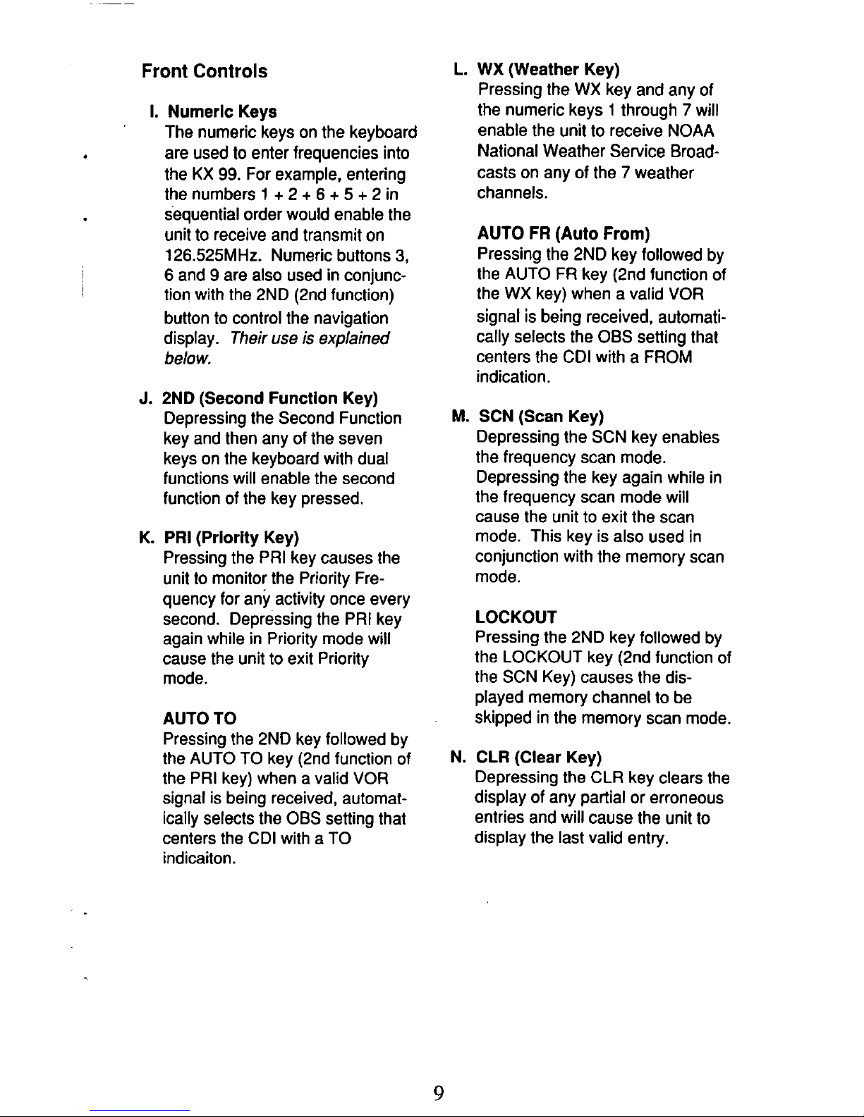
Front Controls
1.
Numeric Keys
'
The numeric keys on the keyboard
are used
to
enter frequencies into
the KX
99.
For example, entering
the numbers
1
+ 2 + 6 + 5 +
2 in
sequential order would enable the
unit
to
receive and transmit on
126.525MHz. Numeric buttons
3,
6 and 9 are also used in conjunction with the 2ND (2nd function)
button
to
control the navigation
display.
Their
use
is explained
below.
j
L. WX (Weather Key)
Pressing the WX key and any of
the numeric keys
1
through 7 will
enable the unit
to
receive NOAA
National Weather Service Broadcasts on any of the
7
weather
channels.
AUTO FR (Auto From)
Pressing the 2ND key followed by
the AUTO
FR
key (2nd function of
the
WX
key) when a valid
VOR
signal is being received, automatically selects the OBS setting that
centers the CDI with a FROM
indication.
J.
2ND
(Second Function Key)
Depressing the Second Function
key and then any of the seven
keys on the keyboard with dual
functions will enable the second
function of the key pressed.
K. PRI (Prlorlty Key)
Pressing the PRI key causes the
unit
to
monitor the Priority Frequency for any activity once every
second. Depressing the PRI key
again while in Priority mode will
cause the unit
to
exit Priority
mode.
AUTO TO
Pressing the 2ND key followed by
the AUTO
TO
key (2nd function of
the
PRI
key) when a valid
VOR
signal is being received, automatically selects the OBS setting that
centers the CDI with a
TO
indicaiton.
M.
SCN (Scan Key)
Depressing the SCN key enables
the frequency scan mode.
Depressing the key again while in
the frequency scan mode will
cause the unit to exit the scan
mode. This key is also used in
conjunction with the memory scan
mode.
LOCKOUT
Pressing the 2ND key followed by
the LOCKOUT key (2nd function of
the SCN Key) causes the dis-
played memory channel
to
be
skipped in the memory scan mode.
N.
CLR (Clear Key)
Depressing the CLR key clears the
display of any partial or erroneous
entries and will cause the unit
to
display the last valid entry.
9
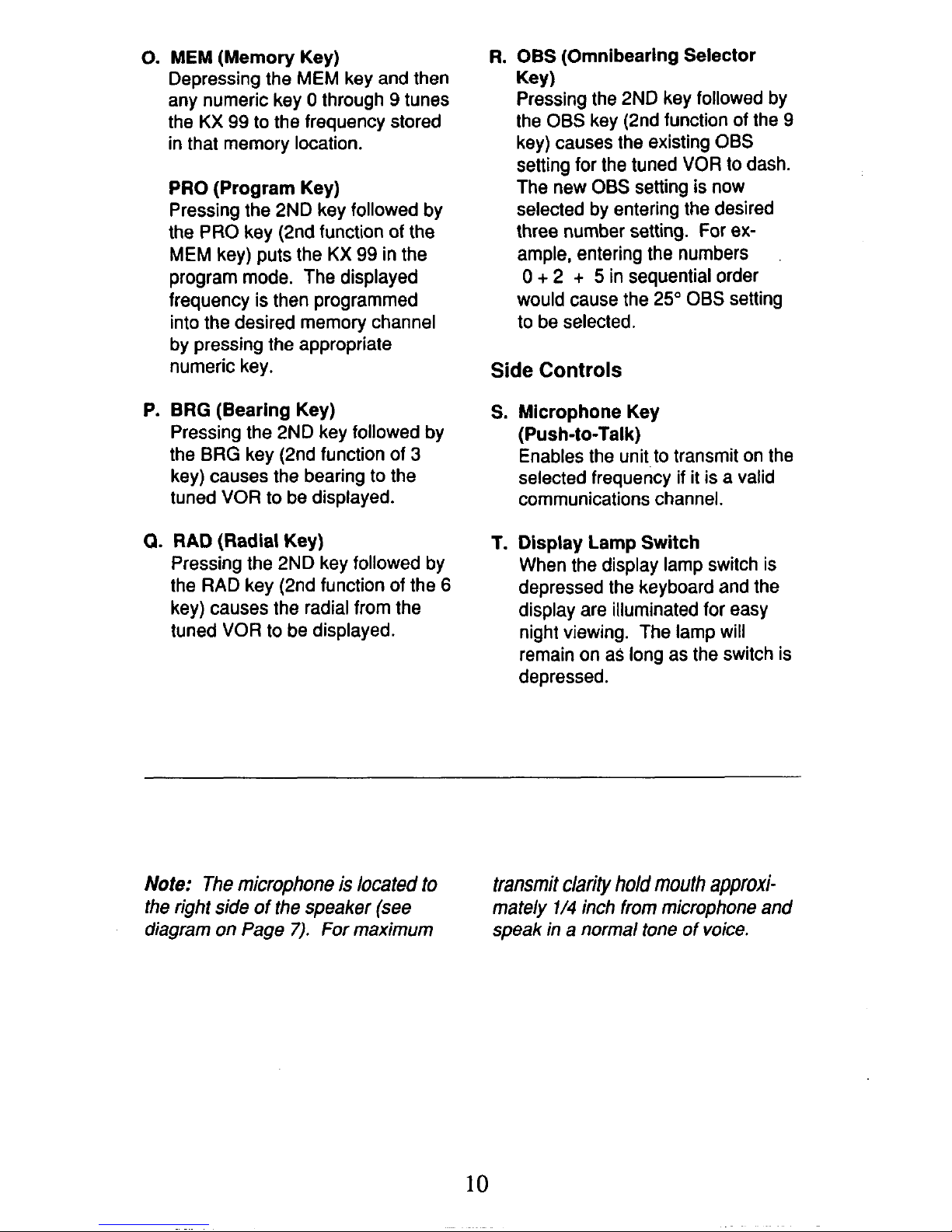
0.
MEM
(Memory Key)
Depressing the
MEM
key and then
any numeric key
0
through 9 tunes
the
KX
99
to
the frequency stored
in that memory location.
PRO (Program Key)
Pressing the 2ND key followed by
the PRO key (2nd function of the
MEM
key) puts the
KX
99
in the
program mode. The displayed
frequency is then programmed
into the desired memory channel
by pressing the appropriate
numeric key.
P.
ERG
(Bearing Key)
Pressing the 2ND key followed by
the
BRG
key (2nd function of
3
key) causes the bearing
to
the
tuned
VOR
to
be displayed.
0.
RAD
(Radial Key)
Pressing the 2ND key followed by
the RAD key (2nd function
of
the
6
key) causes the radial from the
tuned VOR
to
be displayed.
R.
OBS
(Omnibearing Selector
Key
1
Pressing the 2ND key followed by
the
OBS
key (2nd function of the 9
key) causes the existing
OBS
setting for the tuned VOR
to
dash.
The new
OBS
setting is now
selected by entering the desired
three number setting. For ex-
ample, entering the numbers
0
+
2 + 5
in sequential order
would cause the 25"
OBS
setting
to
be selected.
Side
Controls
S.
Microphone Key
(Push-to-Talk)
Enables the unit to transmit on the
selected frequency
if
it
is a valid
communications channel.
T.
Display Lamp Switch
When the display lamp switch is
depressed the keyboard and the
display are illuminated for easy
night viewing. The lamp
will
remain on as long as the switch is
depressed.
Note:
The microphone
is
located
to
the right side of the speaker (see
diagram on Page
7).
For maximum
transmit clarity
hold
mouth
approxi-
mately
1/4
inch from microphone and
speak in a normal tone of voice.
10
 Loading...