

Page 1

Pilot's Guide
KTR 909/909A
B
UHF Communications
Transceiver
Page 2

WARNING
The enclosed technical data is eligible for export under Licanse Designation
NLR and is to be used solely by the individual/organization to whom it is
addressed. Diversion contrary to U.S. law is prohibited.
COPYRIGHT NOTICE
Copyright ©1995 Honeywell International Inc.
All rights reserved.
Reproduction of this publication or any portion thereof by any means without
the express written permission of Honeywell International Inc. is prohibited.
For further information contact the Manager, Technical Publications;
Honeywell; One Technology Center; 23500 West 105th Street; Olathe,
Kansas 66061. Telephone: (913) 712-0400.
Page 3
UHF TRANSCEIVER
GENERAL INFORMATION
This pilot’s guide contains information about and instructions for operating the KTR
909/909A UHF Comm Transceiver with the KFS 599A UHF Comm Control Head.
The KTR 909 must be installed and operated with a KFS 599A UHF Comm
Control Head. The KTR 909A can be operated with either a KFS 599A UHF
Comm Control Head or a Radio Management System (RMS) using the ARINC 429
interface. This pilot’s guide only covers operation using the KFS 599A UHF
Comm Control Head. Refer to the RMS operating procedures on using the KTR
909A in an RMS installation.
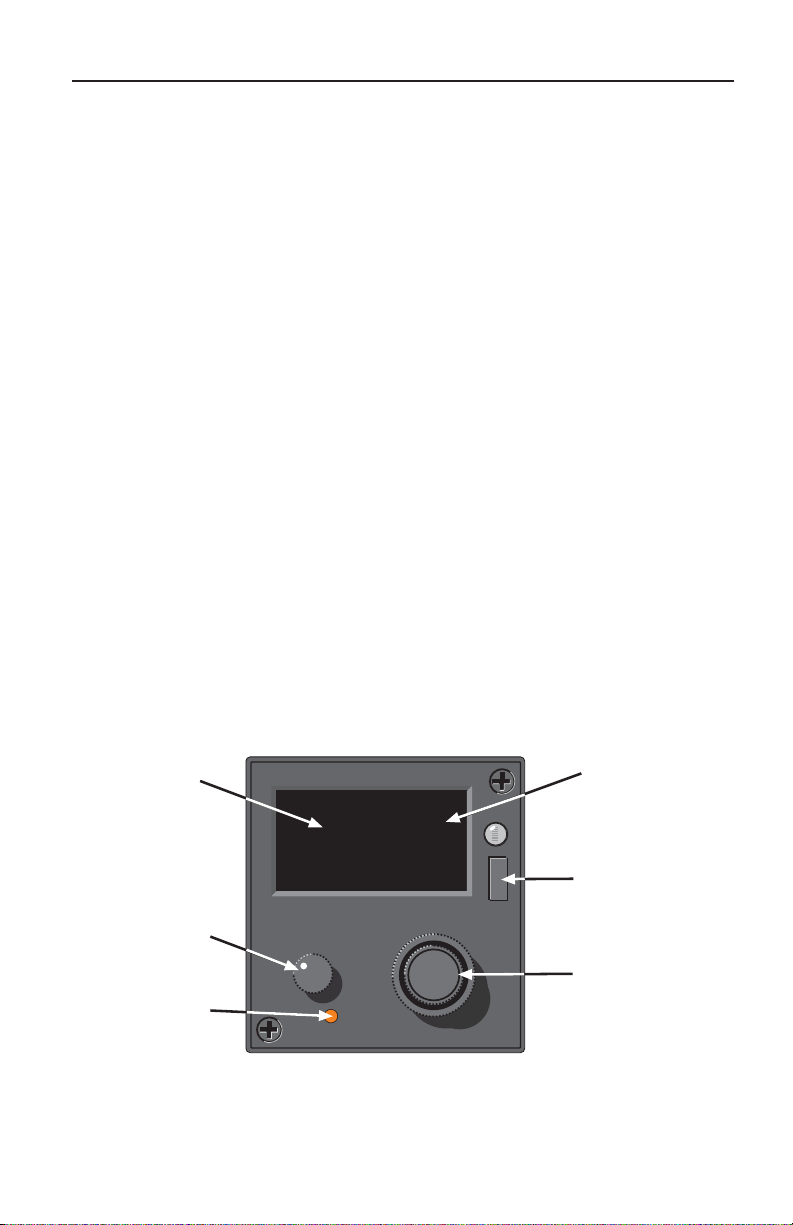
CONTROLS AND DISPLAYS
Controls
This section describes the operational controls of the KFS 599A UHF Comm
Control Head. The following controls are described:
• On/Off/Vol/Test Knob
• Channel Select Button
• Frequency/Channel Select Knob
• Push Tone Button
• Mode Select Button
Display
On/Off/Volume
and Test Knob
Channel Select
Button
B
CH20
399.97
UHF
VOL
OFF
CHAN
PUSH
TEST
MN
PUSH
TONE
1
TX
GD
Annunciators
M
O
D
E
Mode Select Button
Frequency/Channel
Select Knob and
Push Tone Button
Page 4
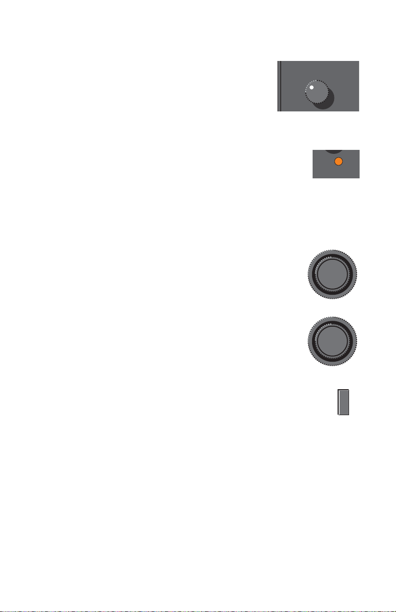
On/Off/Vol/Test Knob
U
The On/Off/Vol/Test Knob turns the KFS 599A UHF
Comm Control Head on, off, and adjusts volume when
rotated. Pressing this knob alternately removes and
applies squelch.
On units without volume control, the audio level is controlled by the aircraft audio/radio control system.
OFF
VOL
PUSH
TEST
Channel Select Button
The Channel Select button switches the unit between the manual and
preset frequency selection modes and also enables the programming
mode. Manual frequency selection (when top display line is blank)
allows direct tuning of the frequency. Preset frequency selection (Channel number
displayed in the top line) allows radio tuning using one of the twenty preset channels or the guard frequency. Pressing and holding the CHAN button for more than
three seconds activates the Program Mode.
CHAN
Frequency/Channel Select Knob
• Manual Frequency Mode — Outer knob tunes the transceiver in 1 MHz steps. Inner knob tunes the transceiver in
25 kHz steps.
• Preset/Guard Channel Mode — Both the outer and the
inner knobs change the channel number.
PUSH
TONE
Push Tone Button
Pressing this button activates the 1 kHz tone transmitter test (not
available while in the BOTH receiver mode).
PUSH
TONE
Mode Button
Pressing the MODE button selects the Main, Both, or ADF mode of operation.
The Main mode enables receiving and transmitting on the displayed frequency
and is indicated by the MN annunciator. In the Both mode, the receiver scans
the main and guard frequencies. Both the GD and the MN annunciators illuminate
during scan. When a signal is detected, the receiver stops on the active frequency
and illuminates the active frequency annunciator. Scanning will resume when the
receiver becomes inactive. The ADF mode activates an independent ADF receiver.
M
O
D
E
Displays
This section describes the different display formats of the KFS 599A UHF Comm
Control Head. These are:
• Preset Channel/Guard Display
• Manual Tuning Display
• Programming Mode Display
• ADF Mode Display
2
Page 5

The frequency range of the radio is 225.000 MHz through 399.975 MHz in 25 kHz
increments. When the farthest right digit is 2 or 7, the selected frequency is
XXX.X25 MHz and XXX.X75 MHz respectively. When the farthest right digit is 0
or 5, the selected frequency is XXX.X00 MHz and XXX.X50 MHz respectively
(e.g., when 399.97 is displayed, the selected frequency is 399.975 MHz).
Preset Channel/Guard Display
The Preset Channel/Guard Display
shows the current active channel on the
top line and the tuned frequency on the
bottom line. The example indicates the
radio is on Channel 20 and tuned to
399.975 MHz. The letters “Gd” are displayed on the top line when the Guard
channel is active.
Manual Tuning Display
The Manual Tuning Display shows the
current tuned frequency on the bottom
line with the top line blank. The
example indicates the radio is tuned to
399.975 MHz.
Programming Mode Display
This is available if the programming
option was enabled during installation.
The Programming Mode Display shows
the channel to be programmed on the
top line and the programmed frequency
on the bottom line.
ADF Mode Display
B
CH20
399.97
UHF
B
399.97
UHF
B
∏20
399.97
UHF
TX
MN
GD
TX
MN
GD
TX
GD
M
O
D
E
M
O
D
E
M
O
D
E
This is available if the ADF option was
enabled during installation. When the
ADF Mode is activated, the letters AdF
appear in either the top or the bottom
display line. They will be in the top line
if the manual frequency mode is active
(shown). The letters will be in the
bottom line if the preset channel select
mode is active.
B
TX
AdF
399.97
MN
GD
M
O
D
E
UHF
3
Page 6

Annunciators
Three annunciators are displayed on the right side of the top display line. These
annunciators are:
• Transmit (TX)
• Main (MN)
• Guard (GD)
Transmit Annunciator
The Transmit Annunciator (TX) is illuminated when the microphone is keyed or the
1kHz Tone knob is pressed.
Main Annunciator
The Main Annunciator (MN) is illuminated when the radio is transmitting on the
main frequency, the radio is monitoring the main frequency (Main Mode), or the
receiver is monitoring both the main and the guard frequencies (Both Mode).
While in the Both Mode, the MN and GD annunciators are on.
Guard Annunciator
The Guard Annunciator (GD) is illuminated when the receiver is monitoring both
the main and guard frequencies (Both Mode). While in the Both Mode, the MN
and GD annunciators are on. If the receiver detects a signal on the Guard frequency while in the both mode, the GD annunciator will be illuminated.
DETAILED OPERATING PROCEDURES
This section describes the detailed operating procedures for the KFS 599A UHF
Comm Control Head. The following topics are described:
• Power and Volume Control
• Selecting Receiver Mode
• Transmitting
• Entering a Manual Frequency
• Entering a Preset or Guard Frequency
• Programming a Channel
• X-Mode Operation
• Display Dimming
Power and Volume Control
Power is applied to the KFS 599A and the KTR 909/909A by rotating the
ON/OFF/VOL/TEST knob clockwise from the OFF detent position. The unit may
be turned off at any time by rotating this knob back into the OFF detent position.
Volume is controlled by rotating the ON/OFF/VOL/TEST knob. The audio level for
units without volume control is adjusted using the main aircraft audio/radio control
system.
4
Page 7

Selecting the Receiver Mode
One of three receiver modes may be selected using the Receive Mode Select
(MODE) key. The modes are Main, Both, and ADF.
Main Transmitting and Receiving on the displayed channel is enabled when
the MN annunciator is illuminated.
Both Scanning of both the Guard and Main receiver frequencies. When the
receiver detects a signal on either frequency, scanning stops on the
active channel. The annunciator associated with that frequency is
displayed. Transmitting while in the Both mode is accomplished on the
Main frequency. Scanning resumes when the active frequency becomes
idle.
ADF This is available if the ADF option was enabled during installation. When
the ADF mode is enabled and active, the MN annunciator is illuminated
and the letters AdF appear in the frequency display when preset channel
mode is active or in the channel display when manual frequency mode is
in use. The transmitter is disabled and an independent ADF receiver will
be enabled.
Transmitting
Note:
For normal voice communications, the transmitter is keyed by pressing the microphone PTT button or through the aircraft radio/audio control system, the TX
annunciator will be illuminated. For transmitting digital data, refer to the X-Mode
section.
A transmitter test is available that modulates the carrier with a 1kHz tone. This is
activated by pressing and holding the PUSH TONE button. When this button is
pressed, the TX annunciator will be illuminated.
Transmitting is disabled when the ADF receiver mode is selected or when
in the programming mode. Voice communications are disabled while in
the X-Mode.
Entering a Manual Frequency
The CHAN button is used to switch the radio between manual and preset channel
selection. When a frequency is selected manually, the receive and transmit frequencies are the same. To enter a frequency manually, perform the following
steps:
• Momentarily press the CHAN button to select the Manual Frequency
Mode (top display line is blank).
• Rotate the small Frequency/Channel Select Knob to change the
frequency in 25 kHz steps. Clockwise rotations increase while counterclockwise rotations decrease the displayed frequency.
• Rotate the large Frequency/Channel Select Knob to change the
frequency in 1 MHz steps. Clockwise rotations increase while counterclockwise rotations decrease the displayed frequency.
5
Page 8

Selecting a Preset or Guard Frequency
The CHAN button is used to switch the radio between manual and preset channel
selection. To select a preset frequency:
• Momentarily press the CHAN button to select the Preset/Guard
Frequency Mode (top display line shows either “CH” followed by a
number or “Gd”).
• Rotate either Frequency/Channel Select Knob to cycle through the available channels. Only programmed channels will be displayed. The Guard
channel is located between the highest and lowest numbered programmed frequencies.
Programming a Channel
This is available if the programming option was enabled during installation. This
mode allows programming any one of the 20 preset operating channels or the
Guard channel.
• Programming a channel with identical transmit and receive frequencies
(Simplex)
• Programming a channel with different transmit and receive frequencies
(Semi-Duplex)
• Changing a Semi-Duplex channel to a Simplex channel
• Deleting a programmed channel
Simplex Programming
This procedure will program a channel to have identical transmit and receive frequencies (simplex operation).
• Press and hold the CHAN button for at least three seconds. The top
display line will flash P01 indicating the programming mode is active on
channel 1.
• Rotate either the small or the large Frequency/Channel Select Knob to
change the channel number.
• Momentarily press the MODE button, the frequency display begins to
flash.
• Rotate the knobs to select the desired frequency, refer to the Entering a
Manual Frequency section (if the channel is not programmed, the large
knob will need to be turned first).
• If more channels need to be programmed, press the MODE button and
repeat this procedure.
• Press the CHAN button or wait ten seconds to exit the programming
mode.
The programmed channel will now be available in the Preset/Guard Frequency
Mode.
6
Page 9

Semi-Duplex Programming
This is available if the semi-duplex option was enabled during installation.
Different transmit and receive frequencies (semi-duplex) may be programmed into
every channel except the Guard. If semi-duplex operation is desired, then perform
the following steps:
• Press and hold the CHAN button for at least three seconds. The top display line will flash P01 indicating the programming mode is active on
channel 1.
• Rotate either the small or the large Frequency/Channel Select Knob to
change the channel number.
• Momentarily press the MODE button, the frequency display begins to
flash.
• Rotate the knobs to select the desired transmit frequency, refer to the
Entering a Manual Frequency section (if the channel is not programmed,
the large knob will need to be turned first).
• Momentarily press the PUSH TONE button to select this frequency as the
transmit frequency.
• Rotate the knobs to select the desired receive frequency, refer to the
Entering a Manual Frequency section (if the channel is not programmed,
the large knob will need to be turned first).
• If more channels need to be programmed, press the MODE button and
repeat this procedure.
• Press the CHAN button or wait ten seconds to exit the programming
mode.
This channel has now been programmed with different transmit and receive
frequencies.
Semi-Duplex to Simplex Conversion
To convert a semi-duplex channel to simplex (transmit and receive frequencies are
the same), perform the following steps:
• Press and hold the CHAN button for at least three seconds. The top
display line will flash P01 indicating the programming mode is active on
channel 1.
• Rotate either the small or the large Frequency/Channel Select Knob to
change the channel number.
• Momentarily press the MODE button, the frequency display begins to
flash.
• Rotate the large Frequency/Channel Select Knob until the display shows
dashes (between 399 and 225).
• Momentarily press the PUSH TONE button.
• Press the CHAN button or wait ten seconds to exit the programming
mode.
The former receive frequency is now the transmit and receive frequency.
7
Page 10

Programmed Channel Deprogramming
To deprogram a channel, perform the following steps:
• Press and hold the CHAN button for at least three seconds. The top
display line will flash P01 indicating the programming mode is active on
channel 1.
• Rotate either the small or the large Frequency/Channel Select Knob to
change the channel number.
• Momentarily press the MODE button, the frequency display begins to
flash.
• Rotate the large Frequency/Channel Select Knob until the display shows
dashes (between 399 and 225).
• Press the CHAN button or wait ten seconds to exit the programming
mode.
The channel is now deleted from the programmed channel list.
X-Mode Operation
This is available if the X-Mode option was enabled during installation. The radio
has the ability to be used for transmitting and receiving digital data using the XMode. The X-Mode is activated by the external digital data communication
system. When activated, normal voice communications are disabled and the
audio output is not squelched.
Display Dimming
This is available if the automatic dimming option was enabled during installation.
The display brightness is automatically controlled by the photocell on the front of
the unit.
DISCRETE INPUTS
Certain discrete inputs may have been installed that affect the operation of the
KTR 909/909A. Refer to the flight manual supplement for more information. The
functions available are:
• Control Disable
• Remote Channel Request
• Program Disable
• ADF Enable
• Semi-Duplex Inhibit
• Remote Guard
Control Disable
This switch will enable and disable the front panel controls of the KFS 599A.
8
Page 11

Remote Channel Request
This switch, when momentarily pressed, will perform one of two functions. If the
KFS 599A is in the manual frequency mode, it will change to the preset channel
mode. If the KFS 599A is already in the preset channel mode, it will change the
channel to the next higher programmed channel.
Program Disable
This line will disable and enable the programming function of the KFS 599A. The
Program Disable line is read only during the power-on sequence; any changes
made after power-on are not read.
ADF Enable
This line will enable and disable the ADF mode of the KFS 599A. The ADF
Enable line is read only during the power-on sequence; any changes made after
power-on are not read.
Semi-Duplex Inhibit
This line will disable and enable the use of the semi-duplex feature of the KFS
599A. Any channels programmed as semi-duplex will transmit on the receive frequencies while semi-duplex is disabled. The Semi-Duplex Inhibit line is read only
during the power-on sequence; any changes made after power-on are not read.
Remote Guard Select
While in the Main mode, pressing this switch will select the guard channel.
Pressing this switch while in the Guard mode will select the last active Main frequency.
Faults and Tests
Transmission Time-out Fault
If the transmitter is active for more than 90 seconds, a transmit time-out fault
occurs. This is indicated by the flashing of every illuminated segment of the display. The transmitter will go inactive until the fault is found or an interruption
occurs in the DC power supply. In most cases, the transmission time-out is
caused by the microphone PTT button being stuck or if a transmission exceeds 90
seconds (including 1kHz Tone Test).
1kHz Tone Test
Pressing the PUSH TONE button modulates the signal with a 1kHz tone. This verifies the operation of the transmitter and the audio system. This feature is disabled
while the unit is in the BOTH receive mode.
9
Page 12

NOTES:
10
Page 13

Honeywell International Inc.
One Technology Center
23500 West 105th Street
Olathe, Kansas 66061
FAX 913-791-1302
Telephone: (913) 712-0400
Copyright ©1995 Honeywell International Inc.
All rights reserved.
006-08737-0001
Rev 1 1/95
n
 Loading...