

Page 1

N
KTA870/
Pilot’s Guide
Multi-Hazard Awareness System
KMH880
B
Traffic Advisory System/
Rev. 3 006-18265-0000
Page 2

The information contained in this manual is for reference use only. If
any information contained herein conflicts with similar information
contained in the Airplane Flight Manual Supplement, the information in
the Airplane Flight Manual Supplement shall take precedence.
WARNING
The enclosed technical data is eligible for export under License Designation
NLR and is to be used solely by the individual/organization to whom it is
addressed. Diversion contrary to U.S. law is prohibited.
COPYRIGHT NOTICE
Copyright © 2001, 2002, 2004, 2005 Honeywell International Inc.
All rights reserved.
Reproduction of this publication or any portion thereof by any means without
the express written permission of Honeywell International Inc. is prohibited. For
further information contact the Manager, Technical Publications; Honeywell;
One Technology Center; 23500 West 105th Street; Olathe, Kansas 66061.
Telephone: (913) 712-0400.
Page 3

Revision History
Manual KTA870/KMH880 Pilot’s Guide
Revision 3, January 2005
Part Number 006-18265-0000
This revision clarifies the determination of when other aircraft are on the
ground, and clarifies the GA-EGPWS Self-Test process.
The following pages were changed or added:
Front Cover, Copyright, 14, 53, 54, Back Cover
R-1
Page 4

Revision History
Manual KTA870/KMH880 Pilot’s Guide
Revision 2, January 2004
Part Number 006-18265-0000
This revision is to correct errors and to remove references to a specific
type of database card.
The following pages were changed or added:
Front Cover, Copyright, 37, 41, 46, 59, 60, Back Cover
R-1
Page 5

Revision History
Manual KTA870/KMH880 Pilot’s Guide
Revision 1, March 2002
Part Number 006-18265-0000
This revision incorporates changes from the KGP 560.
R-2
Page 6

Revision History
Manual KTA870/KMH880 Pilot’s Guide
Revision 0, March 2001
Part Number 006-18265-0000
This is the original version of this publication.
R-3
Page 7

KTA 870/KMH 880 Pilot’s Guide
TAS System Components . . . . . . . . . . . . . . . . . . . . . . . . . . . . . . . 1
Traffic Displays: . . . . . . . . . . . . . . . . . . . . . . . . . . . . . . . . . . . . . 1
TAS Controls . . . . . . . . . . . . . . . . . . . . . . . . . . . . . . . . . . . . . . . 1
TAS Introduction . . . . . . . . . . . . . . . . . . . . . . . . . . . . . . . . . . . . . . 2
TAS: . . . . . . . . . . . . . . . . . . . . . . . . . . . . . . . . . . . . . . . . . 3
Section I : TAS Theory of Operation and Symbology . . . . . . . . 5
TAS Operation . . . . . . . . . . . . . . . . . . . . . . . . . . . . . . . . . . . . . . 6
TAS Sensitivity Level . . . . . . . . . . . . . . . . . . . . . . . . . . . . . 6
TAS Surveillance Volumes . . . . . . . . . . . . . . . . . . . . . . . . . 8
(1) Range Tracking Volumes . . . . . . . . . . . . . . . . . . . . 8
(2) Altitude Tracking Volumes . . . . . . . . . . . . . . . . . . . 8
TAS Aural Inhibits . . . . . . . . . . . . . . . . . . . . . . . . . . . . . . . . 8
TAS Traffic Display Symbols . . . . . . . . . . . . . . . . . . . . . . . . . . . 8
Non-Threat Traffic . . . . . . . . . . . . . . . . . . . . . . . . . . . . . . . . 9
Proximity Intruder Traffic . . . . . . . . . . . . . . . . . . . . . . . . . . . 9
Traffic Advisory (TA) . . . . . . . . . . . . . . . . . . . . . . . . . . . . . 10
No Bearing Traffic . . . . . . . . . . . . . . . . . . . . . . . . . . . . . . . 10
Off Scale Traffic . . . . . . . . . . . . . . . . . . . . . . . . . . . . . . . . . 11
TAS Indications and Voice Announcements . . . . . . . . . . . . . . 12
TAS Traffic Advisory Annunciation (TA): . . . . . . . . . . . . . . 12
Section II : TAS Controls and Displays . . . . . . . . . . . . . . . . . . . 15
TAS Controls . . . . . . . . . . . . . . . . . . . . . . . . . . . . . . . . . . . . . . 15
TAS Control & Display; KMD 550/850 . . . . . . . . . . . . . . . . 15
KMD 550/850 Traffic Page (TAS) Operational Controls. . . 16
TAS Control Panel; CP 66B . . . . . . . . . . . . . . . . . . . . . . . 17
Power Switch: . . . . . . . . . . . . . . . . . . . . . . . . . . . . . . . 18
Range Knob: . . . . . . . . . . . . . . . . . . . . . . . . . . . . . . . . 18
Display Select Switch: . . . . . . . . . . . . . . . . . . . . . . . . . 18
Altitude Limit Switch: . . . . . . . . . . . . . . . . . . . . . . . . . . 18
Weather Radar Indicators . . . . . . . . . . . . . . . . . . . . . . . . 19
RDS 81, 82, 84 & 86, RDR 2000, RDR 2100 and
Primus /Collins Color Indicators . . . . . . . . . . . . . . . . . 19
Weather Only Mode . . . . . . . . . . . . . . . . . . . . . . . . . . 20
Weather with TAS Traffic Mode . . . . . . . . . . . . . . . . . 20
TAS Only Mode . . . . . . . . . . . . . . . . . . . . . . . . . . . . . . 21
Wx & TAS Message Formats . . . . . . . . . . . . . . . . . . . . . . 21
TAS Mode Annunciations: . . . . . . . . . . . . . . . . . . . . . 21
TAS Fault Annunciations: . . . . . . . . . . . . . . . . . . . . . 22
Weather Only and Weather w/TAS Mode . . . . . . . . 22
TAS ONLY mode . . . . . . . . . . . . . . . . . . . . . . . . . . . . 22
Section III: TAS Operational Procedures . . . . . . . . . . . . . . . . . . 23
TAS Operating Procedures . . . . . . . . . . . . . . . . . . . . . . . . . . . 24
Before Takeoff . . . . . . . . . . . . . . . . . . . . . . . . . . . . . . . . . 24
Flight Procedures . . . . . . . . . . . . . . . . . . . . . . . . . . . . . . . 24
Table of Contents
Rev 2
i
006-18265-0000
Page 8

KTA 870/KMH 880 Pilot’s Guide Table of Contents
After Landing . . . . . . . . . . . . . . . . . . . . . . . . . . . . . . . . . . 25
Post Flight . . . . . . . . . . . . . . . . . . . . . . . . . . . . . . . . . . . . . 25
Section IV: TAS System Considerations . . . . . . . . . . . . . . . . . . 27
Limitations And Notes . . . . . . . . . . . . . . . . . . . . . . . . . . . . . . . 28
Limitations . . . . . . . . . . . . . . . . . . . . . . . . . . . . . . . . . . . . . 28
Notes . . . . . . . . . . . . . . . . . . . . . . . . . . . . . . . . . . . . . . . . 28
Appendix: TAS Self Test . . . . . . . . . . . . . . . . . . . . . . . . . . . . . . . 29
TAS Self Test . . . . . . . . . . . . . . . . . . . . . . . . . . . . . . . . . . . . . . 30
Failure Conditions: . . . . . . . . . . . . . . . . . . . . . . . . . . . . . . 31
Radio Altimeter . . . . . . . . . . . . . . . . . . . . . . . . . . . . . . . . . 31
Glossary of TAS Terms . . . . . . . . . . . . . . . . . . . . . . . . . . . . . . 32
Abbreviations and Definitions . . . . . . . . . . . . . . . . . . . . . . 32
EGPWS (Optional)
EGPWS Introduction . . . . . . . . . . . . . . . . . . . . . . . . . . . . . . . . . . 35
What is the GA-EGPWS? . . . . . . . . . . . . . . . . . . . . . . . . . . . . 36
Regulatory Standards . . . . . . . . . . . . . . . . . . . . . . . . . . . . . . . 37
GA-EGPWS Functions and Features . . . . . . . . . . . . . . . . . . . . . 39
Aircraft Position . . . . . . . . . . . . . . . . . . . . . . . . . . . . . . . . . . . . 39
Aircraft Altitude . . . . . . . . . . . . . . . . . . . . . . . . . . . . . . . . . . . . . 40
Terrain, Obstacles & Runway Database . . . . . . . . . . . . . . . . . 41
Terrain Inhibit Switch . . . . . . . . . . . . . . . . . . . . . . . . . . . . . . . . 43
Terrain Awareness Display . . . . . . . . . . . . . . . . . . . . . . . . . . . 44
“Look-Ahead” Alerting and Warning . . . . . . . . . . . . . . . . . . . . . 48
Runway Field Clearance Floor (RFCF) . . . . . . . . . . . . . . . . . . 49
Excessive Rate of Descent Alerting and Warning . . . . . . . . . . 50
Inadvertent Descent / Loss of Altitude After Take-Off . . . . . . . 51
GA-EGPWS Altitude Monitoring . . . . . . . . . . . . . . . . . . . . . . . . 52
Altitude Callout . . . . . . . . . . . . . . . . . . . . . . . . . . . . . . . . . . . . . 52
EGPWS NORMAL PROCEDURES . . . . . . . . . . . . . . . . . . . . . . . . 53
GA-EGPWS System Self-Test . . . . . . . . . . . . . . . . . . . . . . . . . 53
Recommended Procedures for EGPWS Warnings In Flight . . 55
“PULL UP” . . . . . . . . . . . . . . . . . . . . . . . . . . . . . . . . . . . . . 55
Recommended Procedures for EGPWS Alerts In Flight . . . . . 55
ADDITIONAL EGPWS INFORMATION . . . . . . . . . . . . . . . . . . . . . 57
Audio Message Priority . . . . . . . . . . . . . . . . . . . . . . . . . . . . . . 57
GA-EGPWS Cockpit Lamps & Switches . . . . . . . . . . . . . . . . . 58
GA-EGPWS System Limitations . . . . . . . . . . . . . . . . . . . . . . . 58
GA-EGPWS Continued Airworthiness and Database
Update Procedures . . . . . . . . . . . . . . . . . . . . . . . . . . . 59
GA-EGPWS Product Support . . . . . . . . . . . . . . . . . . . . . . . . . 60
Rev 2
ii
006-18265-0000
Page 9
KTA 870/KMH 880 Pilot’s Guide
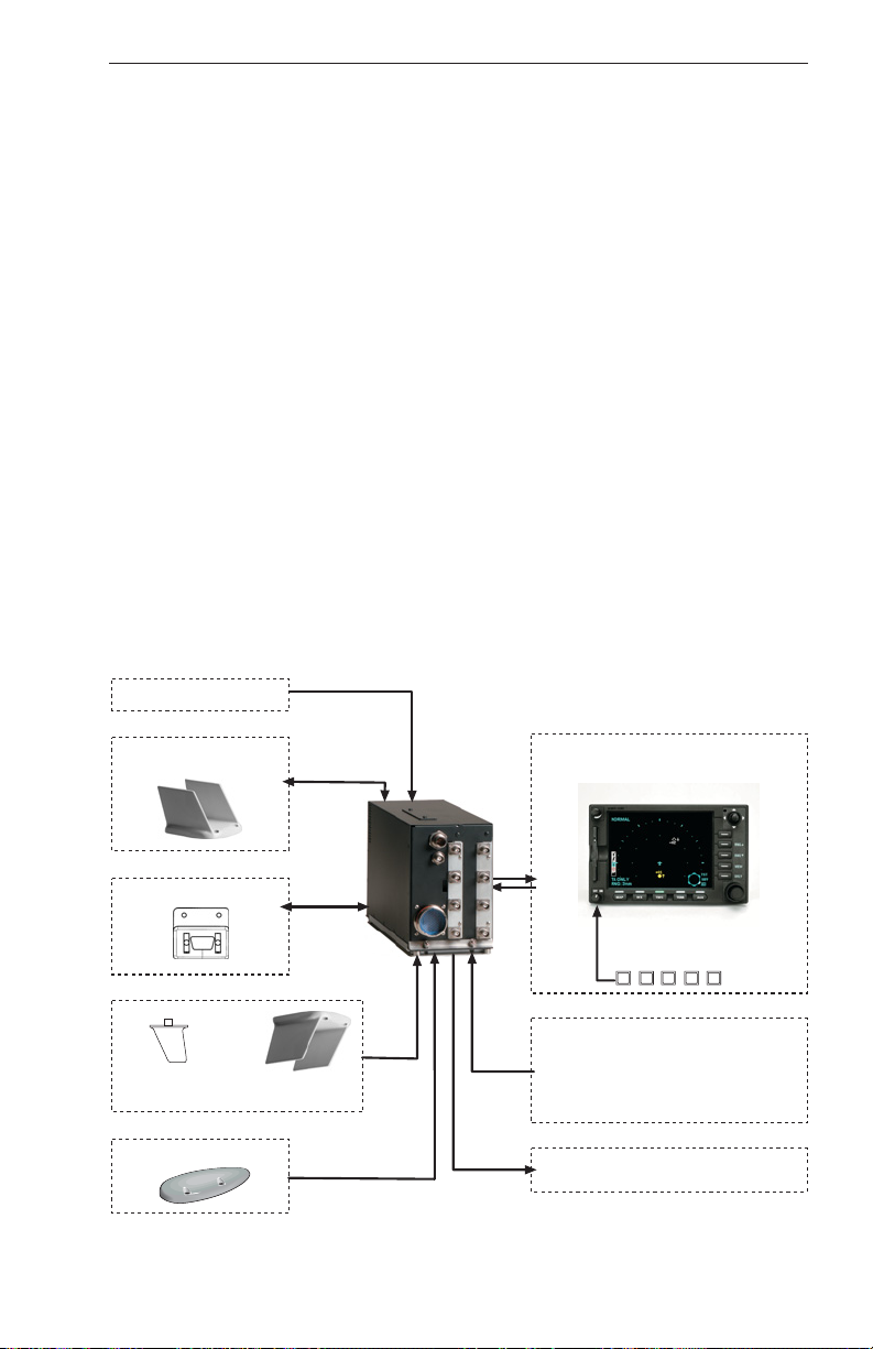
SYSTEM COMPONENTS
TRAFFIC DISPLAYS:
KMD 850
Compatible Radar Indicators via GC 362A
Compatible EFIS
TA/VSI
TAS CONTROLS:
KMD 850
CP 66B TCAS I Controller
Discretes
OPTIONAL EGPWS CONTROLS & DISPLAYS:
KMD 850
Compatible Radar Indicators
Discretes
AUDIO PANEL
Headphone/600 Ohm
TOP ANTENNA
Directional
KA 815
KTA 870/
KMH 880
TAS
PROCESSOR
TRAFFIC DISPLAY/CONTROL
Comprised of the following cards:
TAS System Components
Option 1
KMD 540
KAC 502 (EGPWS) and/or
KAC 504 (TAS)
CONFIGURATION MODULE
CM 805
OR
Option 2
No Control Unit
Discrete Control
TST
SBY
BOTTOM ANTENNA
Omni-Directional
(L-Band)
GPS ANTENNA
KA 92
PWR
AIRCRAFT SYSTEMS
OR
Directional
KA 815
• Barometric Altitude - Gilham, ARINC 429
• Heading - XYZ Synchro
• Suppression
• Discretes
• Outside Air Temperature
SYSTEM STATUS
• TAS VALID
• EGPWS INOP
A/B
FL
KTA 870/KMH 880 Block Diagram
Rev 2 006-18265-0000
1
Page 10

KTA 870/KMH 880 Pilot’s Guide
TAS Introduction
INTRODUCTION
TAS (an acronym formed from the phrase Traffic Advisory System) is an
airborne system used for detecting and tracking aircraft near your own
aircraft. TAS includes a TAS processor, antennas, a traffic display and a
means to control the system. The TAS processor and antennas detect
and track other aircraft by interrogating their transponders. Aircraft
detected, tracked, and displayed by TAS are referred to as Intruders.
TAS analyzes the transponder replies to determine range, bearing and
relative altitude, if the Intruder is reporting altitude. Should the TAS
processor determine that a possible collision hazard exists, it issues
visual and aural advisories to the crew. The visual advisory is shown by
symbols on the traffic display. Complementing the traffic display, TAS
provides appropriate synthesized voice announcements in the cockpit. A
complete list of traffic symbols and announcements is given in the
Theory of Operation and Symbology section of this Pilot’s Guide.
TAS is unable to detect any Intruding aircraft without an operating
transponder. TAS can detect and track aircraft with either an
ATCRBS (operating in Mode A or C) or Mode S transponders.
The traffic display shows the Intruding aircraft’s position. TAS identifies
the relative threat of each Intruder by using various symbols and colors.
The Intruder’s altitude, relative to your own aircraft’s altitude, is annunciated if the Intruder is reporting altitude. A trend arrow is used to indicate
if the Intruder is climbing or descending more than 500 feet per minute.
TAS traffic may be displayed on a weather radar indicator, on a dedicated TAS display, on a TAS compatible EFIS Display Unit or a TA/VSI
(combination traffic display and vertical speed instrument).
TAS modes and functions are controlled by switches located on a TAS
control panel or in combination with various other controls. A description
of controls is given in the Controls and Displays section of this Pilot’s
Guide.
ATC procedures and the “see and avoid concept” will continue to be the
primary means of ensuring aircraft separation. However, if communication is lost with ATC, TAS adds a significant backup for collision avoidance.
Rev 2
2
006-18265-0000
Page 11

KTA 870/KMH 880 Pilot’s Guide
TAS Introduction
TAS:
• Is compatible with the ATC System
• Determines if a threat exists from ATCRBS or Mode S Transponder
equipped aircraft
• Provides display and audio announcement to the crew
- Position information displayed on a traffic display
- Synthesized voice
• Incorporates sensor inputs and sophisticated algorithms to minimize
nuisance visual and aural annunciations.
Rev 2 006-18265-0000
3
Page 12

KTA 870/KMH 880 Pilot’s Guide
THIS PAGE INTENTIONALLY LEFT BLANK
TAS Introduction
Rev 2
4
006-18265-0000
Page 13
KTA 870/KMH 880 Pilot’s Guide
TAS Theory of Operation and Symbology
SECTION I : THEORY OF OPERATION AND
SYMBOLOGY
Section I describes TAS Theory of operation and symbology.
Rev 2 006-18265-0000
5
Page 14

KTA 870/KMH 880 Pilot’s Guide
TAS Theory of Operation and Symbology
TAS OPERATION
TAS monitors the airspace surrounding your aircraft by interrogating the
transponder of the Intruding aircraft. The interrogation reply enables
TAS to compute the following information about the Intruder:
1. Range between your aircraft and the Intruder.
2. Relative bearing to the Intruder.
3. Altitude and vertical speed of the Intruder, if the Intruder is
reporting altitude.
4. Closing rate between the Intruder and your aircraft.
Using this data TAS predicts the time to, and the separation at, the
Intruder’s Closest Point of Approach (CPA). Should TAS predict that
certain safe boundaries may be violated, it will issue a Traffic Advisory
(TA) to alert the crew that closing traffic is nearby.
TAS SENSITIVITY LEVEL
TAS separates the surrounding airspace into two altitude layers. A different sensitivity threshold level for issuing TAs (traffic advisories) is
applied to each altitude layer. Lower altitudes have less sensitive TA
threshold levels to prevent unnecessary advisories in the higher traffic
densities anticipated at lower flight levels, i.e., terminal areas.
TAS has two sensitivity levels (SL) which are described in Table 1, TAS
Sensitivity Levels. SL A is invoked using the following order of precedence: (1) when the TAS aircraft is below 2,000 feet AGL (if equipped
with radio altimeter) OR (2) when the landing gear is Extended (no radio
altimeter installed). SL B occurs under all other flight conditions. Table
2, Typical Traffic Advisory Conditions for Sensitivity Levels describes
what conditions will cause a TA to be issued. If aircraft is not equipped
with either a radio altimeter or retractable landing gear, TAS will stay in
SL B at all times.
Sensitivity
Level
SL A In sensitivity level A, TAS performs surveillance and tracking func-
tions and provides traffic advisories. The conditions for sensitivity
level A are any one of the following:
(1) Own aircraft is in-flight and is below 2,000 feet AGL, if a radio
altimeter is installed.
(2) Own aircraft is in-flight and the Landing Gear is extended, if a
radio altimeter is NOT installed.
Rev 2
DESCRIPTION
6
006-18265-0000
Page 15

KTA 870/KMH 880 Pilot’s Guide
TAS Theory of Operation and Symbology
SL B In sensitivity level B, TAS performs surveillance and tracking func-
tions and provides traffic advisories. The conditions for sensitivity
level B are based on own aircraft in-flight and:
(1) If radio altitude source is installed and own aircraft altitude is
above 2,000 feet AGL (radio altitude).
(2) If radio altitude source is NOT installed and own aircraft has
Landing Gear Retracted.
(3) If the aircraft has a fixed landing gear and no radio altimeter is
installed.
Table 1: TAS Sensitivity Levels
Sensitivity
Level
SL A The following conditions cause TAS to generate a TA in sensitivity
CONDITIONS FOR TRAFFIC ADVISORIES (TAs)
level A:
• TAS calculates that if current closing rate is maintained, separation of less than 600 feet in altitude between own and Intruder will
occur in 20 seconds.
• Separation between own and Intruder is less than 600 feet in altitude and less than 0.20 nautical mile range.
• NAR (Non-Altitude Reporting) Intruder is within 15 seconds or
0.20 nautical mile range.
SL B The following conditions cause TAS to generate a TA in sensitivity
Standby
or Fail • TAs are not generated.
Mode
level B:
• TAS calculates that if current closing rate is maintained, separation
of less than 800 feet in altitude between own and Intruder will
occur in 30 seconds.
• Separation between own and Intruder is less than 800 feet in altitude and less than 0.55 nautical miles in range.
• NAR (Non-Altitude Reporting) Intruder is within 20 seconds or
0.55 nautical mile range.
Table 2: Typical Traffic Advisory Conditions for Sensitivity Levels
Rev 2 006-18265-0000
7
Page 16

KTA 870/KMH 880 Pilot’s Guide TAS Theory of Operation and Symbology
TAS SURVEILLANCE VOLUMES
Surveillance volume is that volume of airspace within which other aircraft
with Mode S or ATCRBS transponders are tracked by own aircraft’s
TAS. The display volume is controlled by the operator and is not necessarily the same as the tracking volume.
(1) Range Tracking Volumes
The size of the range tracking volume is dependent on whether tracking
is occurring on a directional or OMNI antenna and attenuation levels
applied to the transmitted pulses from the TAS processor’s transmitter.
The typical range tracking volume is pictured as a circle.
The maximum range for TAS is 18 nm. However, there are instances
when you may see intruders out to 36 nm. TAS reduces range tracking
volumes in high density areas to reduce the number of receptions to be
processed by TAS and for interference limiting. TAS can track as many
as 45 aircraft and displays up to 30 of them.
(2) Altitude Tracking Volumes
TAS tracks other transponder equipped aircraft that are within a relative
altitude of +/-10,000 feet.
TAS AURAL INHIBITS
TAS will inhibit the aural annunciation using the following order of precedence: (1) below 400 feet AGL (if equipped with radio altimeter) OR (2)
when the landing gear is Extended (no radio altimeter installed). For
installations aboard aircraft with fixed landing gear and no radio altimeter
installed, the aural annunciation is not inhibited by the TAS processor,
unless weight-on-wheels indicates on the ground. The aural annunciation is enabled above 600 feet AGL in aircraft equipped with a radio
altimeter.
TAS TRAFFIC DISPLAY SYMBOLS
TAS will display three different traffic symbols on the traffic display. The
type of symbol selected by TAS is based on the Intruder’s location and
closing rate. Relative bearing and distance to the Intruder are shown by
the position of the Intruder symbol in relation to the own-aircraft symbol.
The symbols change shape and color as separation decreases between
your aircraft and Intruders to represent increasing levels of urgency.
The traffic symbols may also have an associated altitude tag that shows
relative altitude in hundreds of feet. A + sign and number above the
symbol means the Intruder is above your altitude. A - sign and number
beneath indicates the Intruder is below your altitude. A trend arrow
appears when the Intruder’s vertical rate is 500 feet per minute or
greater.
Rev 2
8
006-18265-0000
Page 17
KTA 870/KMH 880 Pilot’s Guide
TAS Theory of Operation and Symbology
No altitude number or trend arrow will appear beside any Intruder that is
Non-Altitude Reporting (NAR).
If TAS direction finding techniques fail to locate the azimuth of another
aircraft, a NO BEARING message appears on the screen when the
Intruder becomes a Traffic Advisory.
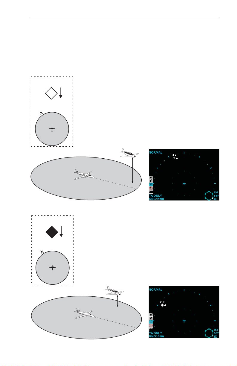
NON-THREAT TRAFFIC
+17
An open white diamond indicates that an Intruder’s relative altitude is greater than ±1200 feet, or its distance is
beyond 5 nm range. It is not yet considered a threat.
This traffic is 1700 feet above your own altitude,
descending at 500 feet per minute or greater.
+1700 Ft. and
Descending
PROXIMITY INTRUDER TRAFFIC
+10
A filled white diamond indicates that the Intruding aircraft is within ±1200 feet and within 5 nm range, but is
still not considered a threat.
This Intruder is now 1000 feet above your aircraft and
descending at 500 fpm or greater.
+1000 Ft. and
Descending
Rev 2 006-18265-0000
9
Page 18
KTA 870/KMH 880 Pilot’s Guide TAS Theory of Operation and Symbology
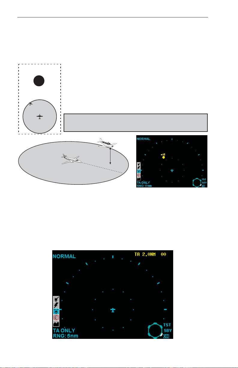
TRAFFIC ADVISORY (TA)
A symbol change to a filled yellow circle indicates that the Intruding aircraft is considered to be potentially hazardous. Depending upon TAS
sensitivity level, TAS will display a TA when time to CPA (Closest Point
of Approach) is 15 to 30 seconds.
+05
Here the Intruder is 500 feet above your aircraft. A
voice is heard in the cockpit, advising:
“Traffic, Traffic”
The crew should attempt to gain visual contact with the
Intruder and be prepared to maneuver upon visual
acquisition.
The crew should take no evasive action
based solely on the TAS display.
+500 Ft.
NO BEARING TRAFFIC
In installations with dual directional antennas with landing gear down,
when omnidirectional antenna is installed on the bottom of the aircraft, or
the intruder is located where the TAS cannot determine the azimuth of
the intruder, a “No Bearing” TA will be annunciated. If traffic can only be
seen by the bottom antenna as described above, a “No bearing” TA
would be annunciated as shown. Here the intruder is two nautical miles
away and co-altitude.
Rev 2
No Bearing TA
10
006-18265-0000
Page 19
KTA 870/KMH 880 Pilot’s Guide
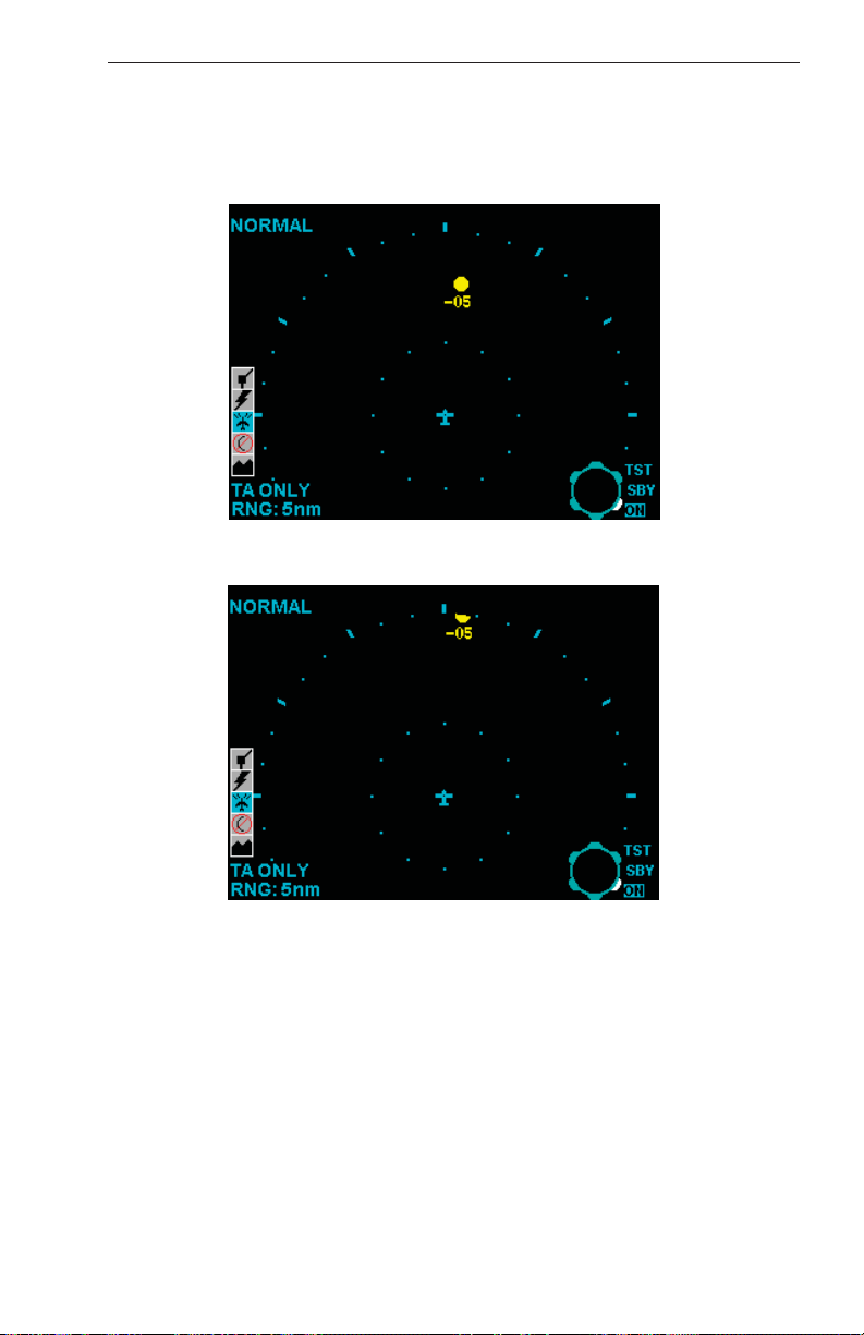
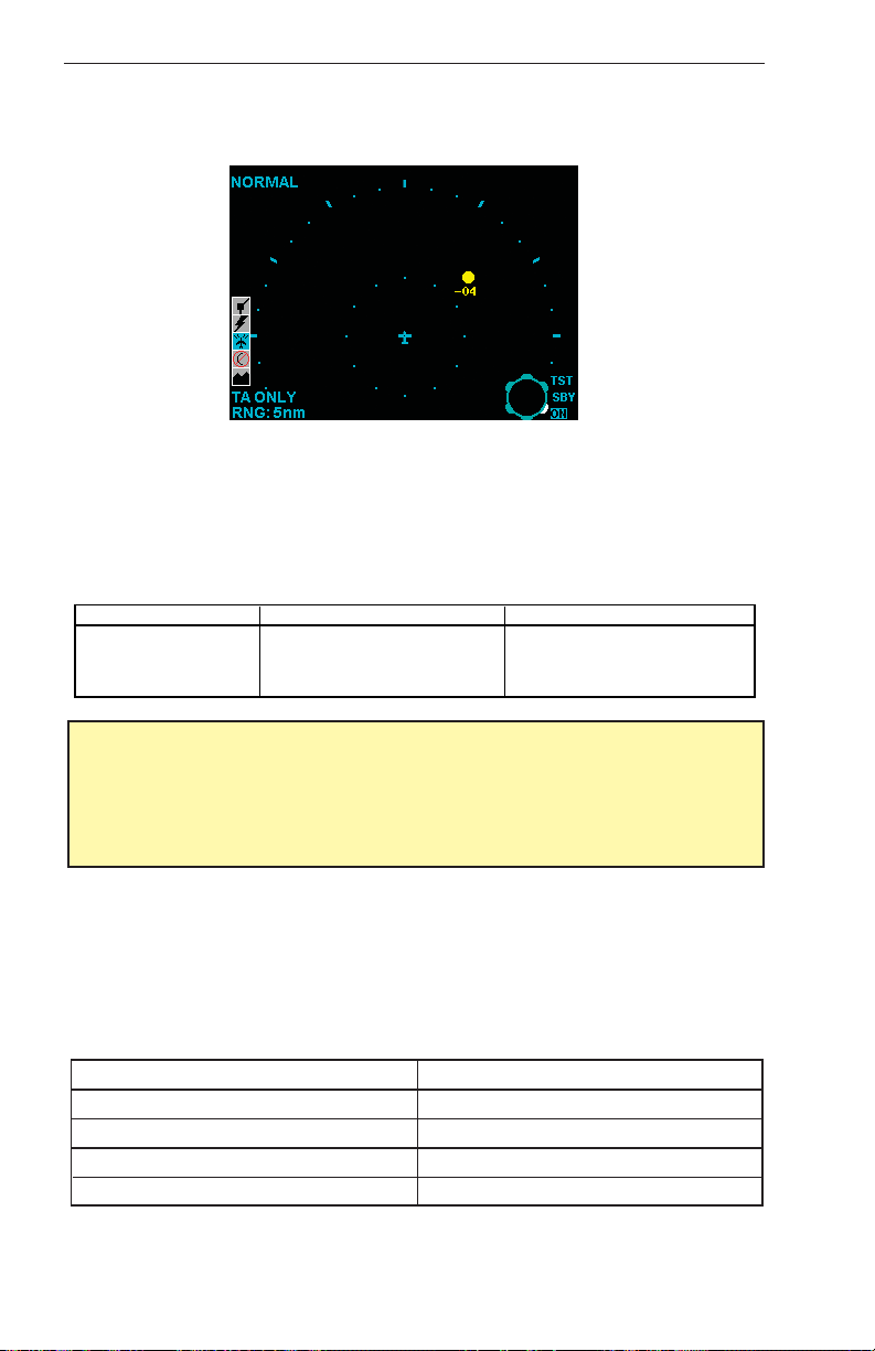
OFF SCALE TRAFFIC
Threat aircraft (TAs) that are beyond the selected display range are indicated by one half of the traffic symbol at the edge of the screen. The
position of the half-symbol represents the bearing of the Intruder.
TA traffic on 5 mile range.
TAS Theory of Operation and Symbology
Same TA traffic; beyond selected range.
Rev 2 006-18265-0000
11
Page 20
KTA 870/KMH 880 Pilot’s Guide TAS Theory of Operation and Symbology
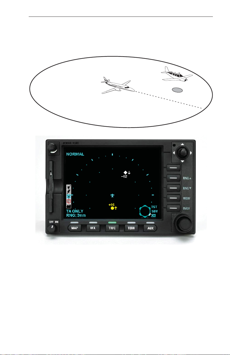
TAS INDICATIONS AND VOICE ANNOUNCEMENTS
“Traffic, Traffic”
Situation:
One Intruder is ahead near the 2:00 o’clock position, between 2 and 3
miles, 400 feet below your altitude and closing. TAS recognizes the
threat and issues a TA.
TAS TRAFFIC ADVISORY ANNUNCIATION (TA):
Aural Visual Crew Response
“TRAFFIC, TRAFFIC”
A filled yellow circle on the
Traffic Display
Conduct visual search for the
Intruder. If successful, maintain
visual acquisition to ensure
safe operation.
IMPORTANT:
The pilot should NOT initiate evasive maneuvers using information
on the Traffic Display only. Use the TA (Traffic Advisory) symbol to
visually acquire the Intruder and be prepared to maneuver upon visual acquisition.
Audio Announcements:
Synthesized voice announcements are issued by TAS over the aircraft
audio system. The following table lists all the audio messages, and advisories, in the TAS vocabulary.
Audio Messages
CONDITION ADVISORY MESSAGE
Traffic Advisory “TRAFFIC, TRAFFIC”
If Previous TA is Active “TRAFFIC”
Self Test Passed “TAS SYSTEM TEST OK”
Self Test Failed “TAS SYSTEM TEST FAIL”
Rev 2
12
006-18265-0000
Page 21

KTA 870/KMH 880 Pilot’s Guide
Intruders may be seen in surrounding airspace, but not on the TAS
display. The situations in which this may happen are:
TAS Theory of Operation and Symbology
• Most small aircraft have one transponder antenna located on the bot-
tom of the aircraft. When own aircraft is above one of these aircraft,
the transponder antenna can be shaded from the TAS interrogations.
When this occurs, the TAS interrogation may not reach the other aircraft’s transponder, or the other aircraft transponder’s reply may not
reach TAS’s antenna. A lack of replies prevents TAS from tracking
intruders. Transponder shading also occurs when the other aircraft is
maneuvering such that line of sight to its transponder antenna is
blocked.
• The TAS directional antennas have a bearing “cone of confusion”.
TAS is able to determine bearings for intruders that are located within
–10 degrees to +70 degrees elevation angle with respect to own aircraft’s horizontal plane for the top directional antenna (+10 degrees to
–70 degrees for a bottom directional antenna). Intruders that are
located outside of those elevation angles will be tracked with no bearing.
• TAS is unable to determine bearings for intruder tracked on the bot-
tom antenna when the own aircraft has a bottom monopole antenna
or a bottom directional antenna but the landing gear is extended. In
this case the intruder will be tracked, but not displayed, unless a
Traffic Advisory is issued against it.
• The other aircraft may have a poor transponder. Ground stations
have more gain and “hear” aircraft at farther distances than TAS.
• TAS is required to reduce transmitter power when in areas of high
density so that it does not adversely affect (overwork) other aircraft
transponders and prevent the ground ATC from tracking them. This is
known as Interference Limiting (IL). IL can reduce the nominal TAS
surveillance range to around 6 nmi. This means that TAS may not
detect a poorly performing transponder until it is much closer.
• TAS has a one-second update rate. When in areas of high density,
TAS may reduce its maximum surveillance range to either 10 nmi or
to the range of the 30th intruder in track plus 1 nmi. This allows TAS
to maintain its one-second update rate.
• TAS has an altitude surveillance volume of –10,000 feet to +10,000
feet relative to own aircraft’s altitude. Any intruders outside this volume are not a threat to own aircraft and therefore are not tracked by
TAS.
Rev 2 006-18265-0000
13
Page 22

KTA 870/KMH 880 Pilot’s Guide TAS Theory of Operation and Symbology
• The display may not be in the correct viewing mode to show the
intruder. The relative altitude modes for the display (KMD 550/850)
are:
- Normal mode: -2700 feet to +2700 feet
- Above mode : -2700 feet to +9000 feet
- Below mode: -9000 feet to +2700 feet
Other control head / display combinations may vary on the altitude
bands.
• Some displays do not always allow the same range on the sides and
aft as out the front. The selected range denotes the range out the
front, and the sides and aft will be shown to a lesser range.
• TAS does not display other aircraft deemed to be on the ground.
When own aircraft is below 1750 feet AGL, any aircraft within 400 feet
of the ground is considered to be on the ground, and therefore not displayed (TAS must be connected to a radar altimeter for this feature).
Rev 3
14
006-18265-0000
Page 23
KTA 870/KMH 880 Pilot’s Guide
TAS Controls and Displays
SECTION II: CONTROLS AND DISPLAYS
TAS CONTROLS
This section describes the control units for the TAS equipment. A couple
of control units are described. The TAS functions can be controlled by
various control panels or discrete switches. Not all the functions
described are required in every installation.
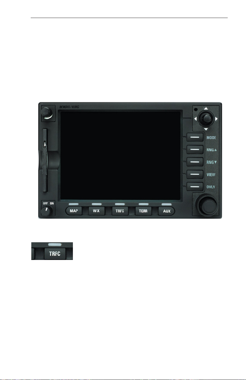
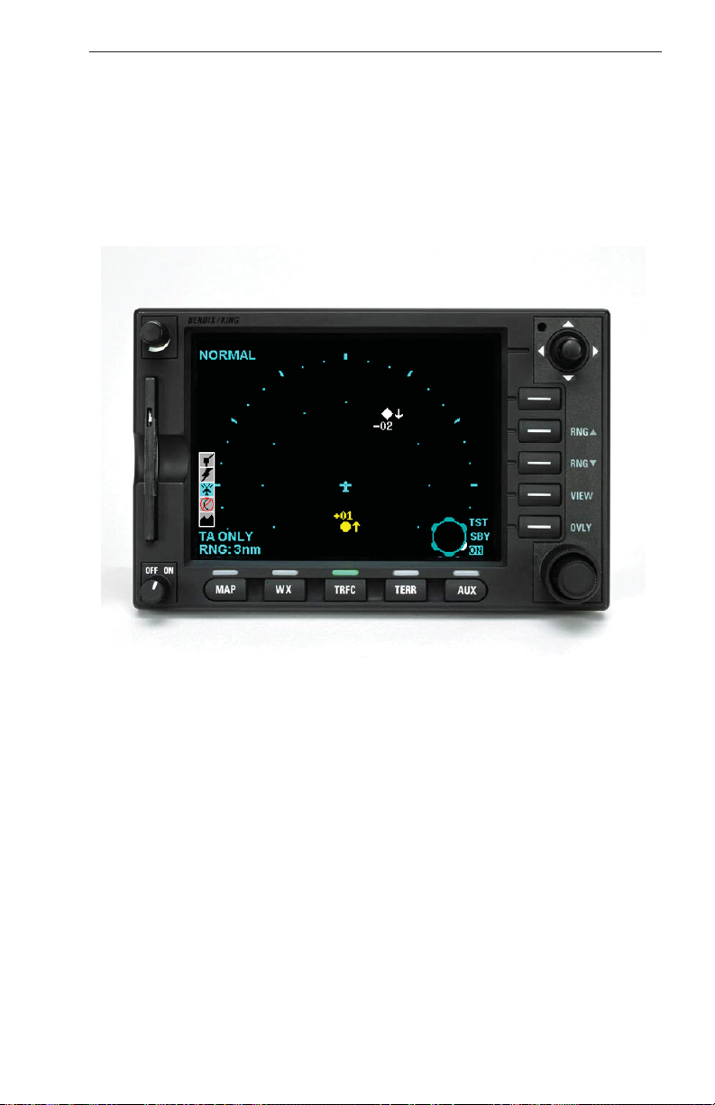
TAS CONTROL & DISPLAY; KMD 550/850
KMD 550/850
TAS Control & Display
To display the traffic page press the TRFC function
select key.
Rev 2 006-18265-0000
15
Page 24
KTA 870/KMH 880 Pilot’s Guide TAS Controls and Displays
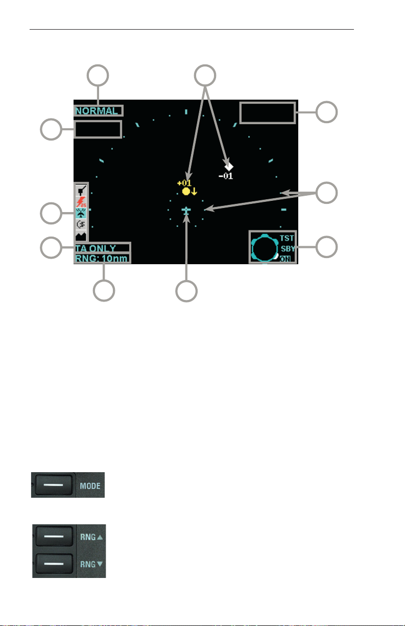
The following illustration defines the data that appears on the Traffic
Display Page:
5
6
7
4
8
3
2
1
1 Display Range - RNG:###nm
2 TAS Operating Mode - TAS TST, TAS SBY, TA Only, or TAS Fail
3 Icon Bar - Displays icons representing data available (black) and
displayed (color)
4 Current Flight Level - FL:###
5 Altitude Volume - NORMAL, ABOVE or BELOW
6 Traffic Intruder Symbols - Indicates type of traffic, altitude of traffic and
vertical trend of traffic.
7 “No Bearing” Intruder Dispay Area - AA X.XNM ±XX
8 Range Rings - Outer ring radius is selected range, inner ring radius is
always two nautical miles
9 Outer Knob Icon - Shows current knob selection
10 Aircraft Symbol - Stylized airplane indicating aircraft position
10
9
KMD 550/850 TRAFFIC Page (TAS) OPERATIONAL CONTROLS
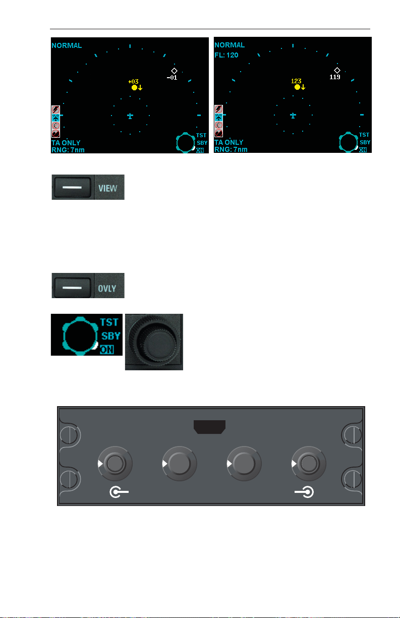
MODE - Toggles the altitude tag between relative or
absolute altitude as shown in Figures 1 and 2. This
key may be enabled or disabled in system configuration.
RNG/RNG - Advances the indicator to the next
range. The upper button increases range, the lower
button decreases it. The selected range is displayed in
the lower left corner of the display with the inner range
ring always 2 nm.
Rev 2
16
006-18265-0000
Page 25
KTA 870/KMH 880 Pilot’s Guide
TAS Controls and Displays
Figure 1
VIEW - Toggles between altitude volume views of
NORMAL, ABOVE and BELOW. This key may be
enabled or disabled in system configuration. NORMAL
displays traffic that is between -2700 feet and +2700
feet relative to own aircraft. ABOVE displays traffic that
is between -2700 feet and +9000 feet relative to own
aircraft. BELOW displays traffic that is between -9000
feet and +2700 feet relative to own aircraft.
OVLY - Allows selection of flight plan for overlay on
traffic data. The GPS flight plan data can be overlaid
on the traffic display, if the desired data is available.
Outer Knob - Selects between Test
(TST), Standby (SBY) and On mode of
operation. This control may enabled or
disabled in system configuration. If the
KMD 550/850 is used with a TCAS II system, this control will not be available.
TAS CONTROL PANEL; CP 66B
TCAS
40
20
ON
SBY
OFF
TST
15
10
5
PUSH TO TST
3
FAIL
TCAS
WX
T/WX
Figure 2
B
ABOVE
NORM
BELOW
PUSH FOR FL
FL
CP 66B
TAS Control Panel
The CP 66B can have up to four separate knobs as shown above.
Depending upon the system interface, the Range Knob and/or Display
Selector may be removed.
Rev 2 006-18265-0000
17
Page 26

KTA 870/KMH 880 Pilot’s Guide TAS Controls and Displays
The CP 66B amber Fail Annunciator will light during self test and in normal operation will flash if a system failure has been detected. If a failure
has been detected, turning the Power Switch to OFF will turn off the
flashing annunciator.
Power Switch:
The OFF position deactivates selector switches and
push buttons and extinguishes FAIL annunciation if on.
The SBY position places the TAS in Standby mode. In
Standby mode, surveillance and tracking operations
are disabled and the traffic display is blanked except for a “TAS STBY”
(“TCAS STBY”) mode annunciation.
The ON position enables the tracking and surveillance operations at the
selected range, display and altitude limit.
Pressing the TEST button in the center of the knob initiates a comprehensive self test lasting approximately eight seconds. Refer to the
Appendix for a description of the self test function.
Range Knob:
The TAS RANGE knob is used to select the range on the
traffic display. The range selections are 3, 5, 10, 15, 20,
and 40. All ranges are in nautical miles.
Note:
This feature may not be available in all installations or this feature
may be superseded by a range control on the traffic display bezel.
Display Select Switch:
The Display Select Switch is used in installations where
the weather radar indicator is the traffic display. It selects
between T/Wx (TAS w/Weather), Wx (Weather Only), and
TCAS (Traffic Only) presentations on the radar screen.
Details of the various modes are described later in this
section under Weather Radar Indicators.
ON
SBY
OFF
15
10
5
TCAS
WX
T/WX
20
TST
40
3
Altitude Limit Switch:
The Altitude Limit Select Switch selects altitude display
limits. It has no effect on the TAS logic giving TAs. There
are three selections available.
ABOVE - Traffic that is between 8700 feet above and 2700 feet below
own aircraft will be displayed. Typically ABOVE is used during the climb
phase of flight.
NORM - Traffic that is between 2700 feet above and 2700 feet below will
be displayed. Typically NORM is used during the en route phase of
flight.
Rev 2
18
ABOVE
NORM
BELOW
006-18265-0000
FL
Page 27

KTA 870/KMH 880 Pilot’s Guide
TAS Controls and Displays
BELOW - Traffic that is between 2700 feet above and 8700 feet below
will be displayed. Typically BELOW is used during the descent phase of
flight.
The FL (Flight Level) push button in the center of the Altitude Limit
Select Switch replaces Intruder’s relative altitude with absolute altitude
for 15 seconds. During this period the altitude is displayed in flight level
format. That is, 19,000 ft. is displayed as 190. After 15 seconds the
absolute reading reverts to relative altitude.
The FL function is flagged below 18,000 feet MSL on most traffic displays unless barometric corrected altitude is available from an air data
source. FL is not inhibited on the Radar indicator when used with
GC 362A.
If FL is selected while inhibited, “FL - - -” will show in place of own flight
level.
WEATHER RADAR INDICATORS
RDS 81, 82, 84 & 86, RDR 2000, RDR 2100 and Primus /Collins Color Indicators
The GC 362A TAS Graphic Processor allows TAS traffic to be displayed
on a variety of Color Radar indicators. A T/Wx (TAS/Weather) select
button is required to switch between Weather Only, Weather with TAS
Traffic overlaid and TAS Only display modes. The T/Wx switch may be
a separate momentary push button or included on another control panel.
Compatible Weather Radar Indicators
Brand Mode
Bendix/King
Collins
Honeywell
B
GC 362A
Rev 2 006-18265-0000
RDS-81,82,84,86 & RDR 2000/2100
WXR System with IND-270
200/300SL/400/870/P90/650/800
BRT
RNG 5
Wx
VP
MAP
NAV
TEST
GAIN
+10
-02
BENDIX
-10
WX ON
ON
TST
SBY
OFF
UP
0
DN
19
LOG
RNG
RNG
TRK
TRK
TILT
Page 28

KTA 870/KMH 880 Pilot’s Guide TAS Controls and Displays
WEATHER ONLY MODE
In this mode of operation, only
weather radar information is
displayed until a Traffic
80
Advisory is issued by the TAS
Processor. The range is controlled by the weather radar
range control in this mode of
operation. When a Traffic
60
Advisory occurs, the display
will revert to the default TAS
display (either TAS Only or
WX
TA AUTO
40
20
Weather/TAS Overlay) selected during installation by the
pop-up default discrete. When TAS determines the Traffic Advisory is
over, the display will revert to the weather radar picture. The TAS mode
is annunciated by TA AUTO in the lower left hand corner of the screen.
WEATHER WITH TAS TRAFFIC MODE
A full time TAS display overlays the weather display in this
mode. The display origin may
be either at the bottom of the
screen or the center of the
screen, depending on the specific installation. Weather will
be displayed in the upper 90°
or 120° sector, depending on
which radar is being used.
Weather is blanked in the
areas where TAS traffic is displayed. The range displayed in
this mode is that which was selected for weather radar. If weather radar
is in the standby mode or other non-radar mode, the display will be the
same as that in the TAS Only mode. This mode is maintained unless
another mode is manually selected. The TAS operational mode is
annunciated along with the pilot selected weather radar mode in the
lower left hand corner of the screen unless the radar is in standby, in
which case the TAS mode is displayed in the upper right hand corner.
Rev 2
20
006-18265-0000
Page 29

KTA 870/KMH 880 Pilot’s Guide
TAS ONLY MODE
TAS Controls and Displays
In this mode the screen’s origin
point is 1/3 up from the bottom
RNG 5
of the screen. Only TAS information is displayed. This mode
is maintained unless another
mode is manually selected.
-05
+25
The range displayed is that
selected on the TAS control
panel. A 2 nm range ring is
displayed on ranges 3, 5, 10,
and 15 nm. The 2 nm range
TA ONLY
ring consists of discrete dots
(cyan) at each of the 12 clock
positions. The 2 nm range ring is not displayed on ranges 20 and 40 nm;
instead, a half-range ring is displayed. The half-range ring consists of discrete dashes (cyan). The TAS operational mode is annunciated in the
lower left hand corner of the screen.
Note:
On the “TAS ONLY” display “WX ON” will be annunciated in the
upper right hand corner if the weather radar is transmitting. See Weather
Radar operating guide.
At power-up the screen initially displays the Radar with TAS Overlay
mode. When the Test mode is selected on the TAS control panel the self
test pattern is displayed unless TAS system failures are detected. If system failures are detected the screen is blanked and a list of faults is displayed.
WX & TAS MESSAGE FORMATS
TAS Mode Annunciations:
TEXT Color Description
TCAS STBY (Blue) TAS in Standby
TEST (Blue) TAS in TEST
TA ONLY (Blue) TA ONLY Mode
TA AUTO (Blue) TA ONLY Pop-Up
Note:
When the Radar is placed in Standby, the TAS mode annunciation
is moved to the upper right hand corner and the display is in the WX only
or TAS/WX modes.
Rev 2 006-18265-0000
21
Page 30

KTA 870/KMH 880 Pilot’s Guide TAS Controls and Displays
TAS Fault Annunciations:
Weather Only and Weather with TAS Mode.
In the event of a failure, all TAS information will be removed from the display. One of the following failure messages will be annunciated in the
upper left corner of the screen.
TEXT
TCAS (Yellow) TAS System Failure.
GP FAIL (Yellow) GC362A Failure.
Additional failure information will be available in the TAS ONLY mode, if
the failure will permit mode change.
Color Description
TAS ONLY Mode
In the event of a failure, all TAS information will be removed from the display. If the failure will disallow mode change, the mode shall revert to the
Weather Only mode and the fault shall be displayed as above.
Otherwise, one or more of the following failure message will be annunciated in yellow text.
TCAS SYSTEM FAIL TCAS PROCESSOR
UPPER ANTENNA LOWER ANTENNA
RADIO ALT #1 RADIO ALT #2
ATTITUDE HEADING
TRAFFIC DISPLAY #1 TRAFFIC DISPLAY #2
ALT DATA #1 & #2 GP RAM
NO RADAR 429 DATA NO TCAS 429 DATA
Rev 2
22
006-18265-0000
Page 31

KTA 870/KMH 880 Pilot’s Guide
TAS Operational Procedures
SECTION III: OPERATIONAL PROCEDURES
TAS Traffic Display Test Page
SECTION III DESCRIBES OPERATION OF THE TRAFFIC
ADVISORY SYSTEM
Rev 2 006-18265-0000
23
Page 32

KTA 870/KMH 880 Pilot’s Guide TAS Operational Procedures
TAS OPERATING PROCEDURES
TAS warns the operator with an aural and visual Traffic Advisory whenever TAS detects another transponder equipped aircraft and predicts the
Intruder to be a threat. The pilot should NOT initiate evasive maneuvers
using information from the traffic display only or on a traffic advisory (TA)
only, without visually sighting the traffic. These displays and advisories
are intended only for assistance in visually locating the traffic and lack
the resolution and coordination ability necessary for use in evasive
maneuvering. The flight crew should attempt to visually acquire the
intruder aircraft and maintain/attain a safe separation in accordance with
the regulatory requirements and good operating practice. If the flight
crew can not acquire the aircraft, air traffic control should be contacted to
obtain any information that may assist concerning the intruder aircraft.
Based on the above procedures minor adjustment to the vertical flight
path consistent with air traffic requirements are not considered evasive
maneuvers.
BEFORE TAKEOFF
TAS should be tested using the pilot initiated self test feature during
cockpit preparation. After passing self test, TAS should remain in SBY
before takeoff.
TAS Traffic on the Radar Display:
If the weather radar indicator is used as the TAS Traffic Display, select
Radar to “STBY”, “TST” or “ON”. Note that the weather radar RT is radiating when in the radar is On. See the weather radar operator’s guide
for proper radar operation. Select the “T/WX” (TAS/Weather) Display
Mode switch to display TAS, i. e., “TA AUTO” or “TA ONLY”.
Before taking the active runway, TAS should be turned ON. Range, if
available, may be selected to 10 nm or lower. Above/Norm/Below, if
available, may be selected to ABOVE.
FLIGHT PROCEDURES
The TAS TA (traffic advisory) should alert the flight crew to use extra vigilance to identify the Intruding aircraft. Any time the traffic symbol
becomes a yellow circle or “TRAFFIC, TRAFFIC” is announced in the
cockpit, conduct a visual search for the Intruder. If successful, maintain
visual acquisition to ensure safe separation.
Rev 2
24
006-18265-0000
Page 33

KTA 870/KMH 880 Pilot’s Guide
Use of the TAS self-test function in-flight will inhibit TAS operation for up
to eight seconds.
During initial departure, select the 10 nm TAS range or lower because
the traffic density is the greatest near the airport.
During the climb phase of flight, select the 10 nm range or greater and
continue to use the Above display volume mode, if available. If a TA
occurs, select the 10 nm range or lower on the TAS traffic display.
During cruise, the longer TAS ranges may be used. The
Above/Norm/Below selection should be NORM. A 10 NM (or greater)
range may be selected for high altitude cruise.
During Descent and Approach, Below may be selected using the
Above/Norm/Below switch. A TAS range of 10 nm or lower may be
used.
1. If a stall warning occurs during a TA, immediately execute the stall
recovery procedure. TAS will continue to provide TA alerts during a stall
warning.
2. If a TA occurs while in the landing configuration, conduct a visual
search for the Intruder. A TA does not mandate a missed approach.
3. If a TA is encountered during a high speed buffet, adjust pitch force
as necessary to reduce buffet.
TAS Operational Procedures
4. While it is extremely rare, EGPWS or Wind Shear may issue an alert
while a TA (traffic advisory) is in progress. If this occurs, TAS will automatically inhibit the TAS audio alerts, but visual display of TAs will continue.
AFTER LANDING
After departing the active runway, TAS should be turned to Standby
(SBY) or Off.
Post Flight
If a failure of the TAS system has occurred, give Maintenance as much
specific information about the problem as possible. Avoid phrases such
as “TAS Inop.” Provide information in terms of fault lights lit, audio
announcements, test pattern discrepancies and screen annunciations
that indicate which unit was observed to have failed.
Rev 2 006-18265-0000
25
Page 34

KTA 870/KMH 880 Pilot’s Guide TAS Operational Procedures
THIS PAGE INTENTIONALLY LEFT BLANK
Rev 2
26
006-18265-0000
Page 35
KTA 870/KMH 880 Pilot’s Guide
TAS System Considerations
SECTION IV: SYSTEM CONSIDERATIONS
Traffic Display
SECTION IV EXPLAINS CONSIDERATIONS OF THE TAS SYSTEM;
WARNINGS AND LIMITATION, AND NOTES.
Rev 2 006-18265-0000
27
Page 36

KTA 870/KMH 880 Pilot’s Guide TAS System Considerations
LIMITATIONS AND NOTES
LIMITATIONS
Refer to the Airplane Flight Manual.
NOTES
The capability of TAS is dependent upon the type of transponder in the
Intruding aircraft:
The Intruding aircraft must be equipped with a properly operating
transponder for normal TAS operation. TAS is unable to detect any aircraft without an operating transponder.
If the Intruder is Non-Altitude Reporting (NAR), TAS will display only the
range and bearing. It can issue a TA (Traffic Advisory) based on distance and direction of flight. TAS assumes Non-Altitude Reporting
(NAR) traffic is at the same altitude as your own aircraft.
Options for TAS also include the following:
* The maximum number of targets displayed (3 - 30) can be selected via
the configuration module.
* The TAS display may have pilot selectable range or may be a fixed
range controlled by the aircraft wiring.
* The TAS system can be automatically placed in standby when the air-
craft is on the ground.
* The manually initiated system self test can be inhibited in flight.
* TAS can be wired to give EGPWS and Wind Shear a higher aural
warning priority.
If a radio altimeter is installed, the TAS aural warning (TRAFFIC, TRAFFIC) is inhibited below 400 feet AGL during descent and below 600 feet
during ascent. If no radio altimeter is installed, then the aural warning is
inhibited whenever the Landing Gear is EXTENDED.
It is possible to see an aircraft flying the same course and direction as
your own aircraft, yet TAS may not consider it a threat. TAS calculates
the closure rate of the Intruder, and derives the time to the Closest Point
of Approach (CPA). If there is no closure rate, no advisory will be
issued, unless the Intruder is very close (within approximately 0.2 mile).
Conversely, traffic at the same altitude very far ahead (about 10 miles)
may be shown as a TA by TAS because of a very rapid closure rate.
On a bottom monopole antenna installation, the TAS bearing and display of a Non-Altitude (NAR) aircraft may appear erratic when the intruding aircraft is close in range but distant vertically. This may make the
NAR traffic symbol momentarily disappear or move around the TAS display. The range distance for the NAR will be accurate but the intruder
may be well above or well below your aircraft. Use NORMAL visual scan
techniques to scan for this and other intruding aircraft.
Rev 2
28
006-18265-0000
Page 37
KTA 870/KMH 880 Pilot’s Guide
APPENDIX: TAS SELF TEST
TAS Appendix
THE APPENDIX INCLUDES
A DESCRIPTION OF TAS SELF TEST.
Rev 2 006-18265-0000
29
Page 38
KTA 870/KMH 880 Pilot’s Guide TAS Appendix
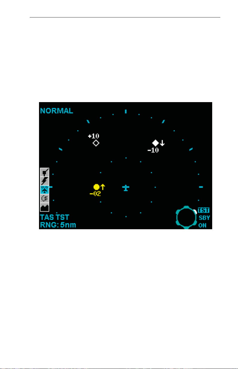
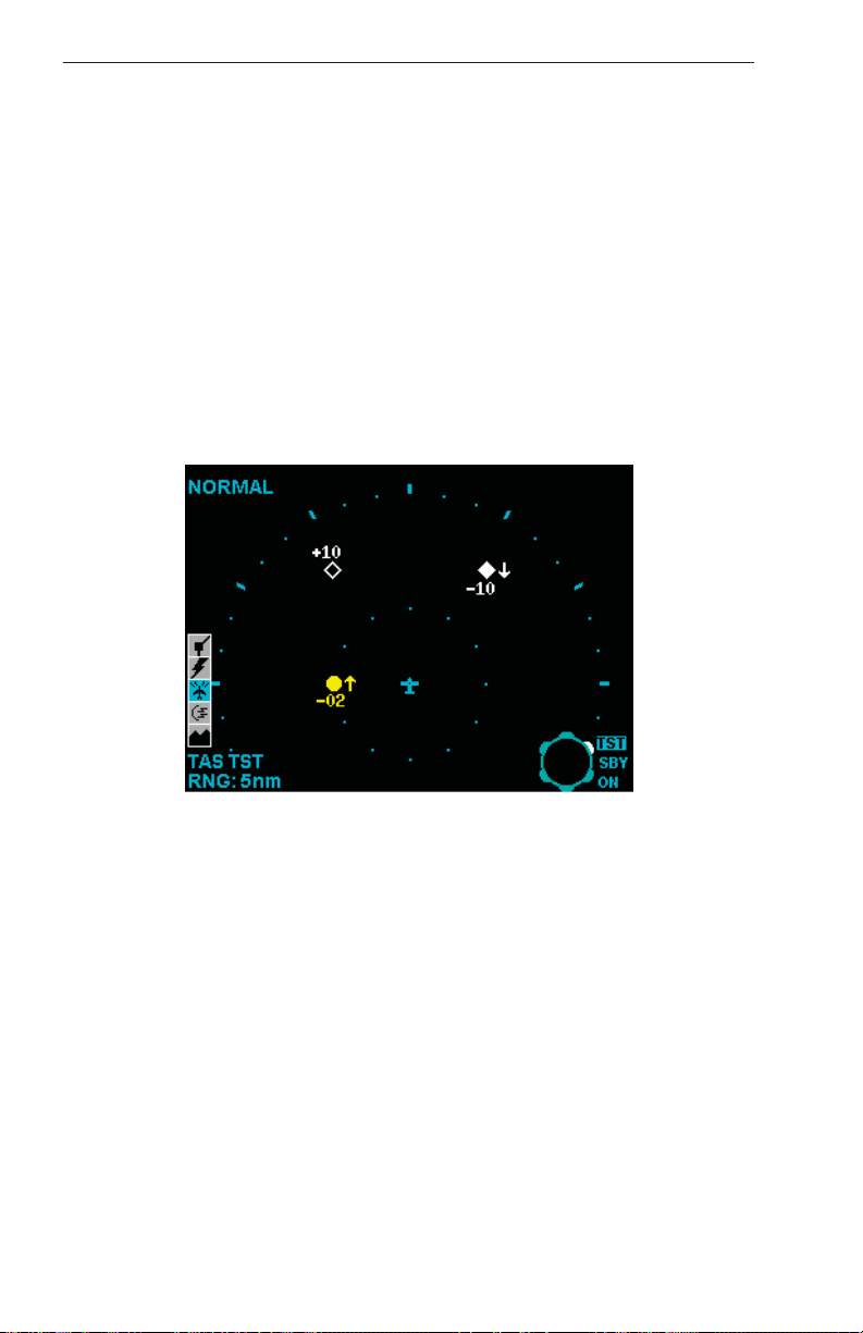
TAS SELF TEST
The TAS self test determines the operational status of the entire TAS system. Select self test on the KMD 550/850. Once begun, self test continues automatically for approximately eight seconds. During self test, normal TAS operation is inhibited. For optimum display during self test, selection of the 5 nm range is recommended.
During the first few seconds of the test sequence, the traffic display
allows verification of each type of Intruder symbol. The test generates
the symbols arranged as shown. The traffic display annunciates the
phrase “TAS TST”.
Use of the TAS self test function in flight will inhibit normal TAS
operation for up to 8 seconds. For this reason, the pilot should use
caution when initiating the test in flight.
KMD 550/850 TAS Test Pattern; 5NM range
A Traffic Advisory (yellow circle) will appear at 9 o’clock, range of 2
miles, 200 feet below and climbing.
Proximity traffic (solid white diamond) will appear at 1 o’clock, range 3.6
miles, 1000 feet below, descending.
Non-Threat traffic (open white diamond) will appear at 11 o’clock, range
of 3.6 miles, flying level 1000 feet above.
Rev 2
30
006-18265-0000
Page 39

KTA 870/KMH 880 Pilot’s Guide
At the conclusion of a successful Self Test, a synthesized voice
announces:
TAS Appendix
“TAS SYSTEM TEST OK”
FAILURE CONDITIONS:
Should a failure be detected during self test, the audio message says:
“TAS SYSTEM TEST FAIL”
A “TAS” flag will be annunciated on the traffic display. A self test failure
may indicate that the auxiliary equipment required for TAS is not operational. Check the associated equipment.
Should a display failure be detected at any time, the Display Fail flag will
appear on the KMD 550/850. A “Display Fail” flag is not caused by the
TAS processor.
RADIO ALTIMETER
If RALT is installed and is inoperative, TAS will be Inoperative.
Rev 2 006-18265-0000
31
Page 40

KTA 870/KMH 880 Pilot’s Guide TAS Appendix
GLOSSARY OF TAS TERMS
ABBREVIATIONS AND DEFINITIONS
AFM or AFMS Airplane Flight Manual or Airplane Flight Manual
Supplement.
AGL Above Ground Level. Height above the ground.
ATC Air Traffic Control. A federally operated ground based system that
manages aircraft traffic flow.
ATCRBS ATC Radar Beacon System. A ground based secondary
radar and airborne transponder system used to monitor traffic.
Absolute Altitude The altitude shown on a traffic display is described
as Absolute whenever the FL mode has been selected. Otherwise, TAS
displays the Relative Altitude between your own aircraft’s pressure altitude and the encoded altitude of the Intruder aircraft.
Altitude Tag Data tag shown above or below threat symbol giving the
relative altitude of the Intruder.
BITE Built-In Test Equipment. A feature of TAS that continuously monitors itself for operational errors.
CPA Closest Point of Approach. CPA refers to predicted point at which
the Intruder will be closest to your own aircraft.
EGPWS Enhanced Ground Proximity Warning System.
FLFlight Level. This is a TAS mode that allows the annunciation of
Absolute Altitude on the traffic display. The traffic display will indicate
the altitude in hundreds of feet, I. E., 190 is 19,000 feet.
GA General Aviation.
Indicated Altitude Altitude shown on the altimeter with barometric cor-
rection setting set to local sea level pressure. Indicated altitude is used
by the crew below 18,000 feet but not used for TAS processing.
Intruder Any aircraft that is in the surveillance range of TAS.
LRU Line Replaceable Unit. A self-contained avionics component that
can be replaced in the field.
Mode A Transponder ATCRBS transponder that replies to ATC interrogations sending identification code but without giving altitude data.
Mode C Transponder ATCRBS transponder that replies to ATC interrogations giving identification code or encoded altitude data.
Rev 2
32
006-18265-0000
Page 41

KTA 870/KMH 880 Pilot’s Guide
Mode S Transponder Transponder that replies to ATC interrogations
giving an ATCRBS identification code, encoded altitude and other data
fields including discrete aircraft address and airspeed capability.
NAR Non-Altitude Reporting traffic.
Non-Threat Intruder An aircraft that has entered the TAS surveillance
volume at a distance greater than 5 miles or altitude greater than 1200
feet above or below your own aircraft.
Pressure Altitude Indicated altitude when barometric pressure is set to
29.92” Hg. (1013mb). Pressure altitude is used by TAS to determine the
relative altitude of traffic.
Proximity Intruder An aircraft that is within 5 miles range and within
1200 feet above or below your own aircraft but does not meet the TAS
definition of a threat.
Rad Alt or RALT Radio Altitude is the height above the ground as determined by a radio altimeter. RALT is used by TAS to inhibit TAs close to
the surface. Radio altitude above terrain is absolute. As such, RALT
height is sometimes referred to as absolute altitude in some systems.
RALT systems typically function below 2,500 ft AGL.
Relative Altitude The difference in altitude between two aircraft. TAS
calculates relative altitude as the difference between your own aircraft’s
pressure altitude and the encoded pressure altitude of the Intruder.
TAS Appendix
Self Test A functional test that determines equipment status. Self test
differs from BITE performance monitoring because it is initiated by the
crew and is not performed continually or automatically.
Sensitivity Level TAS has two sensitivity levels (SL). SL A shall be
automatically invoked using the following order of precedence: (1) when
the TAS aircraft is below 2,000 feet AGL (if equipped with radio altimeter) OR (2) when the landing gear is Extended (no radio altimeter
installed). SL B occurs under all other flight conditions. If aircraft is not
equipped with either a radio altimeter or retractable landing gear, TAS
shall stay in SL B at all times.
Surveillance Volume The volume of airspace surrounding your aircraft
that TAS scans for Intruding traffic. The TAS system scans approximately 20 NM around and 10000 feet above and below the aircraft. The
volume will automatically begin to decrease when flying into a high density area.
TA Traffic Advisory. An audio and visual indication that another aircraft
is a potential threat.
Threat An aircraft that has satisfied TAS threat detection logic and thus
requiring a Traffic Advisory.
Rev 2 006-18265-0000
33
Page 42

KTA 870/KMH 880 Pilot’s Guide TAS Appendix
THIS PAGE INTENTIONALLY LEFT BLANK
Rev 2
34
006-18265-0000
Page 43

KTA 870/KMH 880 Pilot’s Guide
EGPWS Introduction
INTRODUCTION
The Bendix/King General Aviation Enhanced Ground Proximity Warning
System (GA-EGPWS) brings state-of-the-art technology in Terrain
Display, Situational Awareness, Terrain Alerting and Warning, and
Obstacle Alerting and Warning to the General Aviation pilot. The GAEGPWS is an affordable, extremely lightweight, compact and rugged
computer that is easily installed in single- and multi-engine piston aircraft
as well as small turbo-props and other aircraft. The terrain function can
be provided entirely by the KMH 880, or can be provided by a combination of a KTA 870 in combination with a KGP 560.
Based on 30 years experience in the development and advancement of
Ground Proximity Warning Systems for Air Transport, Regional and
Commuter Airlines, Military aircraft and Corporate aviation, Honeywell
brings this vital safety technology to all segments of General Aviation.
Using our proprietary world-wide terrain database, obstacle database,
runway database, state-of-the-art GPS technology, and proven Terrain
Display with Alerting and Warning functions, the system provides the
General Aviation pilot with superior situational awareness with respect to
terrain and known obstacles. In addition, the system contains the most
advanced alerting and warning functionality to warn the pilot of danger
with respect to terrain, man-made obstacles and other primary scenarios
associated with the dangers of Controlled Flight Into Terrain (CFIT).
Use of a terrain display is optional, but recommended in order to
enhance full situational awareness. If a terrain display is not installed in
the system, all alerts and warnings are still present.
This Pilot’s Guide outlines the basic requirements for system operation
and recommended procedures for use of the GA-EGPWS by the
General Aviation pilot. This Guide does NOT supersede FAA Approved
Data or FAA Flight Manual Supplements, or FAA Required Procedures.
Each pilot should be thoroughly familiar with his or her aircraft, its systems, and FAA and/or company requirements for that aircraft as
equipped with the General Aviation Enhanced Ground Proximity
Warning System.
Rev 2 006-18265-0000
35
Page 44

KTA 870/KMH 880 Pilot’s Guide EGPWS Introduction
WHAT IS THE GA-ENHANCED GROUND PROXIMITY WARNING SYSTEM?
The Bendix/King GA-EGPWS is a small lightweight computer that can be
installed in most single- and multi-engine piston aircraft, small turboprop
aircraft and other aircraft in which a Terrain Avoidance & Warning
System is applicable.
The system uses information from an existing GPS (already in the aircraft) or internal GPS receiver contained in the GA-EGPWS computer.
The only other required input is uncorrected barometric pressure from
the aircraft’s transponder or altitude reporting/encoding device. An additional input of Outside Air Temperature (OAT) is optional and recommended. See section on Aircraft Altitude.
The system can also accept inputs from various digital air data computers, when such equipment is available on an aircraft. The terrain database, obstacle database, runway database and alerting / warning functionality are contained in the GA-EGPWS computer, and require no pilot
action for system operation.
Outputs generated by the system are:
* Terrain / Obstacle Display
* Voice alerts / Warnings / Callouts
* Visual alerts / Warnings
During normal flight operations, the system remains essentially silent,
using GPS, altitude and temperature (optional) data in combination with
its various database information to provide the pilot with a display of the
aircraft position relative to surrounding terrain and known obstacles,
thereby providing unprecedented situational awareness for the pilot.
Pilot workload in interacting with the system during normal flight is minimal.
Rev 2
36
006-18265-0000
Page 45

KTA 870/KMH 880 Pilot’s Guide
Should the aircraft fly into danger where a conflict with terrain or a known
obstacle is imminent, the system will provide both visual and aural alerts
and warnings to the pilot. The system also provides alerts and warnings
for excessive rates of descent and inadvertent descents or altitude loss
after take-off.
The system provides an aural altitude callout when 500 feet above runway elevation during a landing approach, and also monitors altimeter
systems in the aircraft to provide alerts for possible altimeter malfunctions or errors.
Pilot reactions to alerts and warnings differ according to weather conditions, visibility, type of warning, phase of flight and aircraft performance
considerations. Pilots should be thoroughly familiar with FAA, company,
or other approved operational procedures as required by their aircraft
and type of operation. Pilots should train to react properly to GAEGPWS alerts and warnings just as one would train to react to an aircraft
stall, engine failure or any other emergency situation.
EGPWS Introduction
REGULATORY STANDARDS
The GA-EGPWS satisfies the requirements for Terrain Avoidance &
Warning Systems (TAWS) as defined by FAA TSO C151b, Class B and
C, when installed in aircraft in accordance with approved procedures.
(See System Installation Manual).
Rev 2 006-18265-0000
37
Page 46

KTA 870/KMH 880 Pilot’s Guide EGPWS Introduction
THIS PAGE INTENTIONALLY LEFT BLANK
Rev 2
38
006-18265-0000
Page 47

KTA 870/KMH 880 Pilot’s Guide
EGPWS Functions and Features
GA-EGPWS FUNCTIONS AND FEATURES
AIRCRAFT POSITION
The GA-EGPWS uses Global Positioning System (GPS) information
from either an aircraft-installed GPS receiver, or an internal GPS receiver
contained in the GA-EGPWS computer itself. It is good for the pilot to be
aware of the actual position source being used by the system, as the
internal GPS is not used for navigation of the aircraft.
GPS signals arrive at an antenna on the aircraft and are then processed
by the GA-EGPWS computer to provide both horizontal (lateral) and vertical position (altitude) information. This position in space is then compared to the terrain, obstacle and runway database information contained in the GA-EGPWS computer to produce a “virtual” picture which
can then be displayed to provide Situational Awareness for the pilot.
Other GPS information such as true track, groundspeed, vertical velocity,
N/S and E/W velocity, and signal accuracy measurements are also
processed by the GA-EGPWS computer to provide a complete picture of
not only the aircraft position in three dimensions, but also an excellent
picture of the aircraft’s flight path.
This total package of information is then used to provide the Terrain
Display for the pilot, and to provide alerting and warning functionality to
protect the pilot and passengers from possible conflicts with terrain,
known obstacles, and other scenarios associated with the dangers of
Controlled Flight Into Terrain (CFIT).
Rev 2 006-18265-0000
39
Page 48

KTA 870/KMH 880 Pilot’s Guide EGPWS Functions and Features
AIRCRAFT ALTITUDE
In addition to the altitude information provided by the GPS, the GAEGPWS uses uncorrected barometric pressure altitude information from
the aircraft’s encoding altimeter, blind altitude encoder or transponder.
This altitude information allows the system to do two main tasks.
First, by using a special “derived-altitude” developed by Honeywell called
“Geometric Altitude”, the GPS and uncorrected pressure altitude information is blended together by the system to provide accurate altitude
information, which is using the same Mean Sea Level (MSL) reference
as the terrain, obstacle and runway databases in the system. The blending functionality of “Geometric Altitude” means it is much less susceptible
to errors or malfunctions in the use of normal altimeter systems. (The
pilot is NOT required to enter an altimeter setting specifically for the GAEGPWS system).
Where aircraft are routinely operated in extreme weather conditions
(either hot or cold), Honeywell strongly recommends the optional temperature input be used with the GA-EGPWS. This additional factor in the
blending formula of “Geometric Altitude” provides an even more accurate
vertical position to the system, and prevents serious discrepancies
between actual altitude and “Geometric Altitude” under extreme temperature conditions, especially during rapid climbing or descending flight
profiles.
The second benefit of using “Geometric Altitude” in the system is that the
pilot will now have an independent monitor of altitude. The system can
detect an abnormal difference between “Geometric Altitude” and the
uncorrected pressure altitude. Optionally, the system can provide a voice
callout and display a message to the pilot should such an abnormal difference occur.
Geometric Altitude
Rev 2
40
006-18265-0000
Page 49

KTA 870/KMH 880 Pilot’s Guide
On some terrain displays, an indication of MSL or GSL altitude will
appear. This altitude is the reference altitude for the display and the terrain awareness algorithm. This reference altitude is based on internally
calculated Geometric Altitude and NOT corrected barometric altitude that
must be used when navigating within the National Airspace System.
Geometric Altitude is the height above mean sea level (MSL) derived
from the GPS receiver, filtered by the vertical figure of merits from the
same GPS and complemented by short term variations in barometric altitude. It represents the aircraft's calculated true height above MSL and
serves as the reference altitude for color-coding of the terrain display and
the altitude input to the look-ahead algorithm. On some displays the
Geometric Altitude number may be labeled ‘MSL', ‘GSL' (Geodetic Sea
Level) or have no label. Exact location and display definition of this altitude is detailed in the Operating Guide and/or Flight Manual
Supplements of the display system.
Because Geometric Altitude is primarily comprised of GPS altitude, this
reference altitude will often differ from cockpit displayed corrected barometric altitude. The geometric altitude is not to be used for naviga-
tion. It is presented to provide the crew with additional situational awareness of true height above sea level upon which terrain alerting and display is based. GPS altitude is an altitude above mean-sea-level and it is
the geodetic height above the WGS-84 ellipsoid corrected by the geoid
height in the GPS receiver itself. With Selective Availability turned off as
currently, the accuracy is usually better than 75 feet and with Selective
Availability turned on, short term accuracy is in the order of 400 feet, but
the geometric altitude should be within 100 feet.
EGPWS Functions and Features
TERRAIN, OBSTACLES & RUNWAY DATABASE
The GA-EGPWS contains a removable database card, which is inserted
into the unit through a slot in the top surface of the computer. This card
contains all the terrain data, known obstacles data (where available), and
runway data used by the system. This card must be installed in the computer for proper operation. Instructions for update procedures and installation of the database card are discussed later in this guide.
Terrain data is supplied from the same proprietary database used by
other Honeywell EGPWS products, and is divided into three regions
worldwide. (See pictures following). The terrain data is divided into grid
patterns of various sizes, from areas about 1/4 nm square resolution to
areas of about 5 nm square. This allows a large area of data to be
stored in the unit, and allows high-resolution data near airports, with
lower resolution data where terrain is not a factor and airports are
sparse.
Rev 2 006-18265-0000
41
Page 50

KTA 870/KMH 880 Pilot’s Guide EGPWS Functions and Features
Data for known obstacles such as towers, buildings, antennas, etc. is
contained on the same data card as the terrain and airport data.
Presently, there are some 70,000-plus obstacles in the database, but
they are all in the area of North America. As more reliable information
becomes available, Honeywell will expand the capability to provide alerting and warning for obstacles in other areas of the world.
Obstacles in the database are those known obstacles more than 100
feet AGL, so obstacles of lower height will not produce GA-EGPWS
“Obstacle” alerts or warnings. However, terrain elevations are “rounded”
up to the next 100 feet, so alerting and warning protection is generally
available for known obstacles that are less than 100 feet AGL.
75°
60°
45°
30°
15°
0°
15°
30°
45°
60°
165°150° 135°120°105° 90° 75° 60° 45° 30° 15° 0° 15° 30° 45° 60° 75° 90° 105° 120°135°150° 165°180°
Regional Database: Americas (shaded areas)
75°
60°
45°
30°
15°
0°
15°
30°
45°
60°
75°
60°
45°
30°
15°
0°
15°
30°
45°
60°
75°
60°
45°
30°
15°
0°
15°
30°
45°
60°
165°150° 135°120°105° 90° 75° 60° 45° 30° 15° 0° 15° 30° 45° 60° 75° 90° 105° 120°135°150° 165°180°
Regional Database: Atlantic (shaded areas)
Rev 2
42
006-18265-0000
Page 51

KTA 870/KMH 880 Pilot’s Guide
EGPWS Functions and Features
75°
60°
45°
30°
15°
0°
15°
30°
45°
60°
165°150° 135°120°105° 90° 75° 60° 45° 30° 15° 0° 15° 30° 45° 60° 75° 90° 105° 120°135°150° 165°180°
75°
60°
45°
30°
15°
0°
15°
30°
45°
60°
Regional Database: Pacific (shaded areas)
Runway database information in the GA-EGPWS computer contains all
known public runways that are 2000 feet in length or longer. This runway data is used to adjust the alerting and warning functions of the system so as to provide a dynamic system that is essentially free of nuisance or unwanted warnings. A list of runways in the database can be
accessed at the Internet website: http:\\ www.egpws.com. A list of the
most recent database versions available for the GA-EGPWS can also be
found there.
TERRAIN INHIBIT SWITCH
The GA-EGPWS requires the installation of a "Terrain Inhibit" switch as
part of the system installation. When engaged by the pilot, this switch will
inhibit all visual and aural alerts and warnings associated with the GAEGPWS. Also, an external annunciator lamp is illuminated and a message will be displayed indicating “Warnings Inhibited”. The terrain display, if installed, remains operational.
The purpose of the "Terrain Inhibit" switch is to allow aircraft to operate
without nuisance or unwanted warnings at airports that are not in the
system database. Examples might be private airports or those with runways shorter than 2000 feet. Additionally, there may be some "VFRonly" airports where unique terrain features are in close proximity to the
runway, and the "Terrain Inhibit" may be used when operating in good
VFR conditions. The "Terrain Inhibit" switch should be NOT engaged for
normal operations.
Rev 2 006-18265-0000
43
Page 52
KTA 870/KMH 880 Pilot’s Guide EGPWS Functions and Features
TERRAIN AWARENESS DISPLAY
The GA-EGPWS can be interfaced to numerous types of cockpit displays. Graphical display of GA-EGPWS terrain and obstacle data is the
most important enhancement to Situational Awareness. This is especially true for lower performance aircraft. In addition to showing terrain
ahead of the aircraft, (depending on configuration settings and display
types) the system shows Geometric altitude (MSL/GSL), Magnetic
Heading or Track. The color and intensity of the terrain displayed instantly alerts the pilot to areas of dangerous terrain and conversely to areas of
less precipitous terrain. Range of the Terrain Display is selectable by the
pilot from 1 nm to 320 nm, again depending upon the display type
installed in the aircraft.
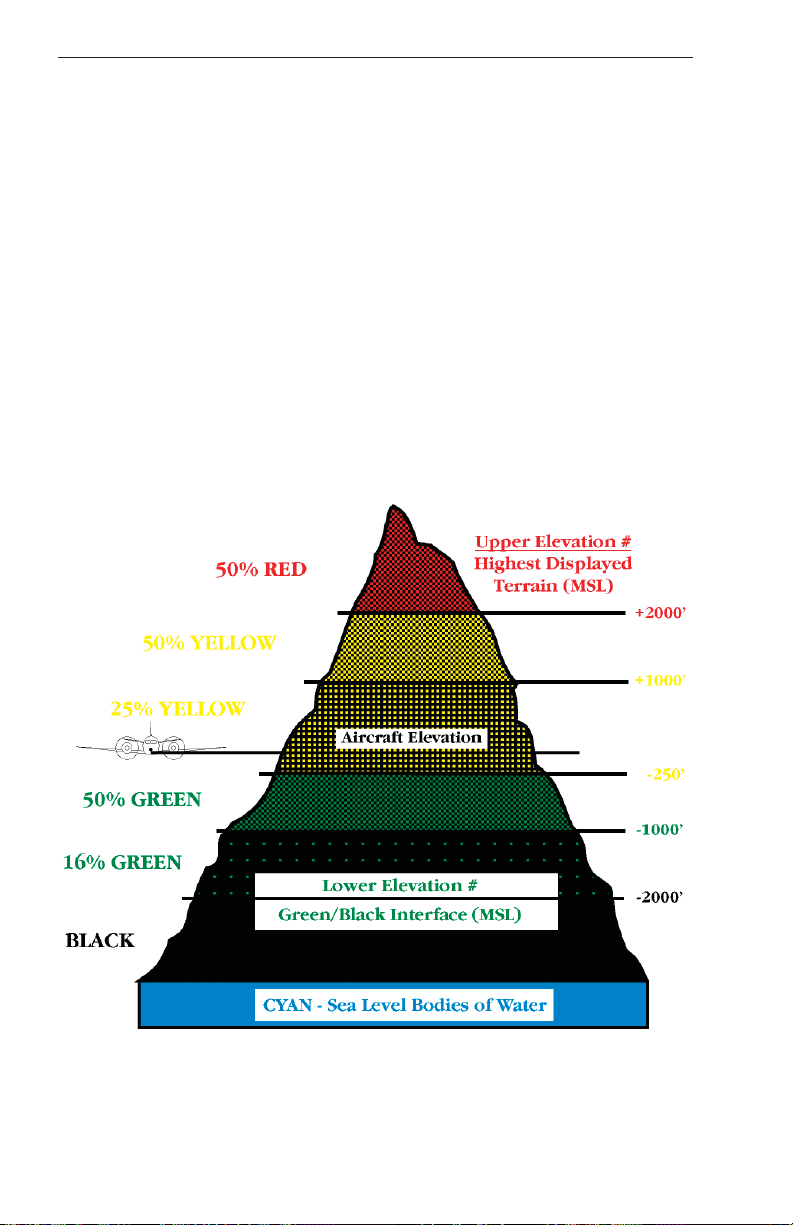
The following figure shows the Terrain Display color patterns when the
aircraft is at lower altitudes, with terrain near or above the aircraft altitude
for the display range selected by the pilot.
Rev 2
44
006-18265-0000
Page 53
KTA 870/KMH 880 Pilot’s Guide
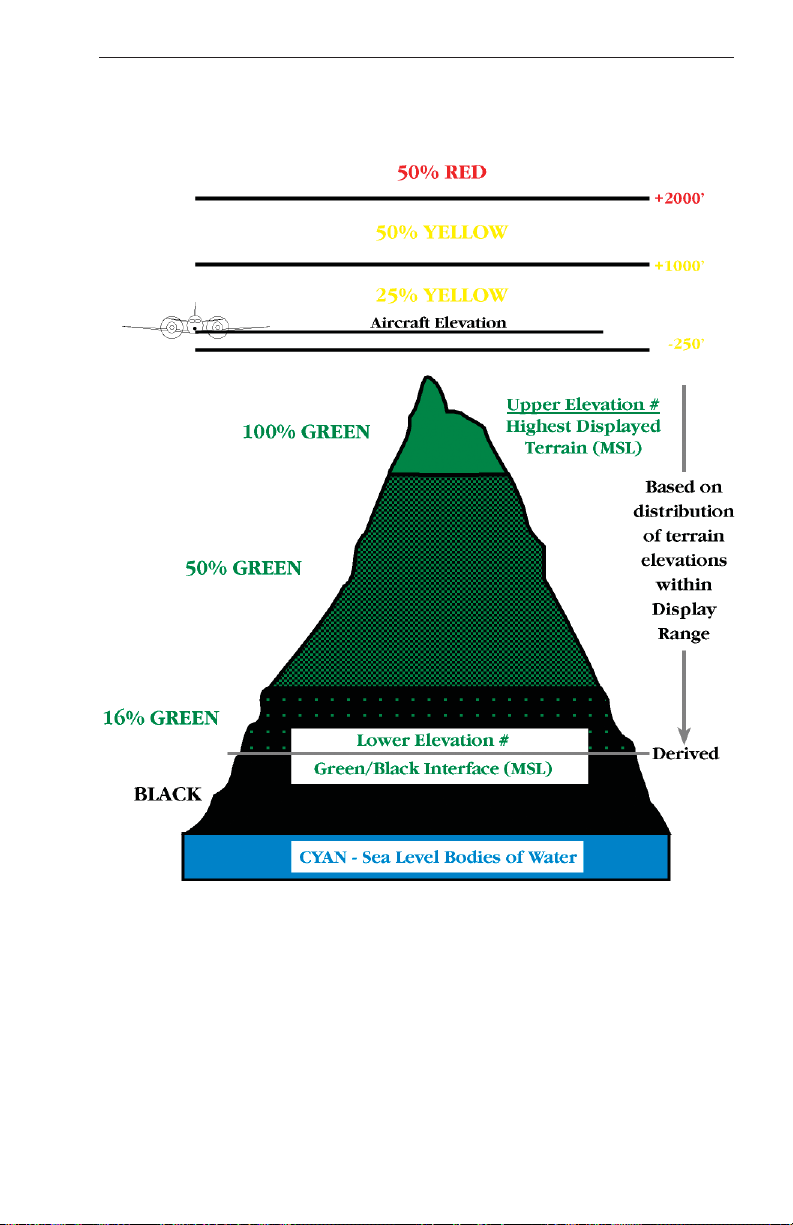
The following figure shows the Terrain Display color patterns when the
aircraft is at higher altitudes, where terrain is a least 250 feet below the
aircraft altitude for the display range selected by the pilot.
EGPWS Functions and Features
The system will adjust colors on the Terrain Display automatically as the
aircraft altitude changes. The Terrain Display also transitions between
the lower altitude “relative” display and the higher altitude “peaks” display
automatically, so no pilot action is required for system operation.
Depending upon display type aircraft interface capabilities, the Terrain
Display can show various presentations of the terrain around and in front
of the aircraft, i.e. a “rose” or 360° compass view, a 1/3 - 2/3 360° view,
90° or 120° “arc” views with or without a vertical profile.
Rev 2 006-18265-0000
45
Page 54
KTA 870/KMH 880 Pilot’s Guide EGPWS Functions and Features
Installations without a heading input into the GA-EGPWS will either have
a NORTH oriented or BLANK display when on the ground. Depending
upon configuration the display will automatically transition to a TRACK
UP (MAG XXX TRK) orientation upon reaching a configurable airspeed
(typically 10 to 45 kts GPS ground speed). Once the display has transitioned to the TRACK UP display, the depiction of terrain is oriented to the
current GPS track of the aircraft. The display will continue in this TRACK
UP mode until transition below a configurable GPS speed when it will
automatically transition back to either the NORTH UP or BLANK display.
The BLANK display annunciates that the display is currently unavailable
(DISPLAY UNAVAIL).
Installations with a heading input into the GA-EGPWS will present a terrain depiction oriented to the current heading of the aircraft (HEADING
UP). These installations will not transition between different orientations
of the display and will typically present the current heading as `MAG
XXX HDG'.
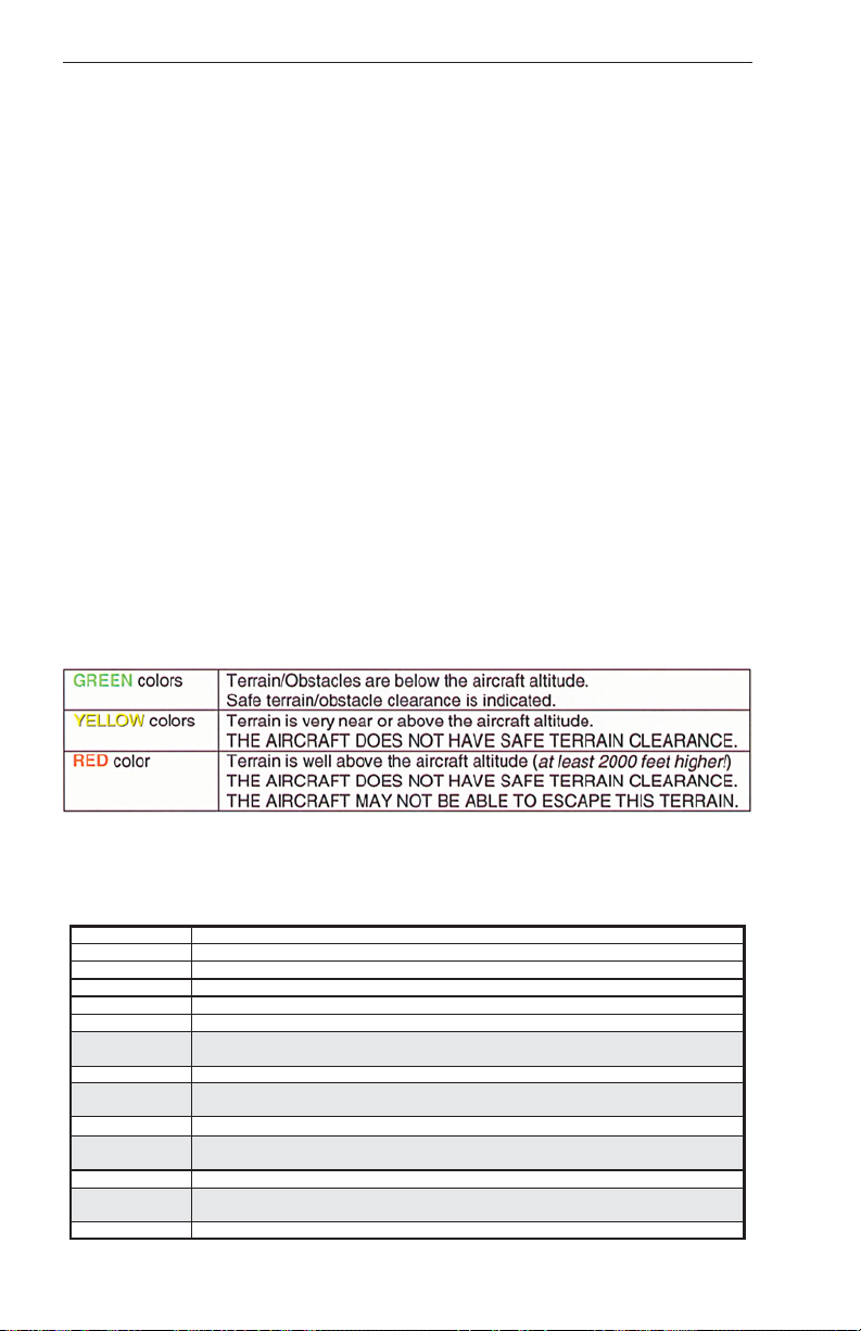
The most important function of the system is to provide the pilot with easily interpreted information about terrain/obstacles relative to the aircraft,
and thus increase the pilot’s Situational Awareness. In brief, when using
the Terrain Display during flight, the normal presentation of green, yellow
and red colors indicate:
The following chart outlines all the various colors used by the GAEGPWS Terrain Display and their functions in providing Situational
Awareness to the pilot. Some display types may not support all colors
Color
Solid Red
Solid Yellow
50% Red Dots
50% Yellow Dots
25% Yellow Dots
Solid Green
(Peaks only)
50% Green Dots
(Peaks only)
16% Green Dots
(Peaks only)
Black
16% Cyan
(Peaks only)
Magenta Dots
Rev 2
Indication
Terrain/Obstacle Threat Area - Warning.
Terrain/Obstacle Threat Area - Caution.
Terrain/Obstacle that is more than 2000 feet above aircraft altitude.
Terrain/Obstacle that is between 1000 and 2000 feet above aircraft altitude.
Terrain/Obstacle that is 250 feet below to 1000 feet above aircraft altitude.
Shown only when no Red or Yellow Terrain/Obstacle areas are within range on the
display. Highest Terrain/Obstacle not within 250 feet of aircraft altitude.
Terrain/Obstacle that is 250 feet below to 1000 feet below aircraft altitude.
Terrain/Obstacle that is the middle elevation band when there are no Red or Yellow
terrain areas within range on the display.
Terrain/Obstacle that is 1000 to 2000 feet below aircraft altitude.
Terrain/Obstacle that is the lower elevation band when there are no Red or Yellow
terrain areas within range on the display.
No significant Terrain/Obstacle.
Area having sea level elevation (0 feet MSL).
Unknown terrain. No terrain data in the database for the magenta shown.
46
006-18265-0000
Page 55

KTA 870/KMH 880 Pilot’s Guide
EGPWS Functions and Features
listed, or may display colors in slightly different densities than those listed, but the system is designed to present the most appropriate Terrain
Display capable on the various display types which are usable by the
system.
NOTE: Green colors indicating terrain/obstacles below the aircraft are
NOT shown when the aircraft is on the ground, to reduce display clutter
and to show only terrain that is significantly higher than the aircraft in the
departure area. Green colors will appear when the aircraft has climbed
approximately 500 to 800 feet above the elevation of the runway.
The following pictures show two examples of the Terrain Display.
Display Orientation
Geometric Altitude
Displayed as MSL or GSL
Here Magnetic Heading is
up and at 150°.
Display Range
Nautical Miles
Range Rings
Outer ring is selected
range, inner ring is half
the selected range. Here
outer ring is 20nm and the
inner ring is 10nm.
Peaks Elevation
Maximum elevation
displayed over minimum
elevation. Here maximum
elevation is 14,300ft. and
minimum is 10,000ft.
GA-EGPWS Terrain Display at 12,000 feet approaching Aspen, CO
Rev 2 006-18265-0000
47
Page 56
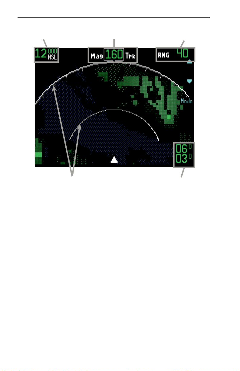
KTA 870/KMH 880 Pilot’s Guide EGPWS Functions and Features
Geometric Altitude
Displayed as MSL or GSL
Range Rings
Outer ring is selected
range, inner ring is half
the selected range. Here
outer ring is 40nm and the
inner ring is 20nm.
Display Orientation
Here Magnetic Track is
up and at 160°.
Display Range
Nautical Miles
Peaks Elevation
Maximum elevation is
displayed over minimum
elevation. Here maximum
elevation is 6,000ft. and
minimum is 3,000ft.
GA-EGPWS “Peaks” Terrain Display at 12,000 feet near Seattle, WA
“LOOK-AHEAD” ALERTING AND WARNING
Using aircraft position, altitude and flight path information, the system
provides an envelope of protection for the aircraft that is independent
from the Terrain Awareness Display. This “Look-Ahead” function compares the aircraft flight path to terrain and obstacle database information,
and distance to known runways.
When the “Look-Ahead” function detects a terrain or obstacle threat
approximately one minute ahead of the aircraft, the voice alert “Caution
Terrain, Caution Terrain” (or “Caution Obstacle, Caution Obstacle”) is
given, and a bright, solid yellow “threat area” is shown on the Terrain
Display. Should the aircraft flight path continue toward the threat area,
the alert message will repeat approximately every 7 seconds.
Rev 2
48
006-18265-0000
Page 57
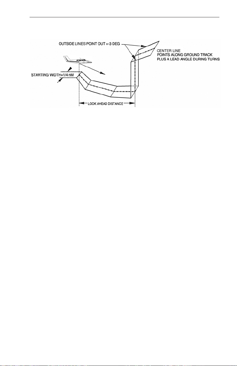
KTA 870/KMH 880 Pilot’s Guide
The following illustration is a general representation of the “Look-Ahead”
functionality.
If the aircraft flight path approaches to within approximately 30 seconds
of a threat area, the voice message “Terrain Ahead” (or “Obstacle
Ahead”) or optionally “Terrain Terrain, Pull Up” (or “Obstacle-Obstacle,
Pull Up”) will be given continuously and the threat area on the Terrain
Display will be shown in a bright, solid red color.
In either case, when the pilot reacts and changes the aircraft flight path
to one that will safely avoid the detected threat area, the voice alerts will
cease and the threat area(s) shown on the Terrain Display will be
removed.
EGPWS Functions and Features
RUNWAY FIELD CLEARANCE FLOOR (RFCF)
The GA-EGPWS provides additional alerting protection for situations
where aircraft descend to an altitude that is too low considering the aircraft’s distance from a known runway. This is called the Runway Field
Clearance Floor (RFCF).
NOTE: This alert function is ONLY active when the aircraft is within 5 nm
of a known runway in the system database.
Using the aircraft distance to a known runway and Geometric Altitude,
the system establishes a “floor” of protection below the aircraft.
Penetration of this floor will cause the yellow caution alert annunciator
lamp to illuminate, and the voice alert “Too Low, Too Low” to be heard.
If aircraft altitude continues to descend, the voice alert will be heard
again, and at an increasing frequency.
When the pilot reacts to the alert and climbs back above the RFCF for
the current distance from the known runway, the annunciator lamp will
extinguish and the voice alerts will cease.
Rev 2 006-18265-0000
49
Page 58

KTA 870/KMH 880 Pilot’s Guide EGPWS Functions and Features
The following figure is a graphical representation of the Runway Field
Clearance Floor.
Runway Field Clearance Floor (RFCF)
EXCESSIVE RATE OF DESCENT ALERTING AND WARNING
The GA-EGPWS uses both GPS Vertical Velocity and pressure altitude
to compute vertical velocity information when the aircraft does not provide specific air data for this purpose. In either case, when the aircraft is
descending toward terrain at a high rate for its relative altitude above terrain, the system will provide alerting and warning to the pilot. This function is always active.
The following graph represents the envelope of protection provided for
Excessive Rate of Descent scenarios:
Excessive Descent Rate
Rev 2
50
006-18265-0000
Page 59

KTA 870/KMH 880 Pilot’s Guide
Initially, the voice alert “Sink Rate” will be heard, and the yellow caution
alert annunciator lamp will illuminate. If the aircraft continues in the high
rate of descent, the “Sink Rate-Sink Rate” voice alert will be repeated at
an increasing frequency.
Should the aircraft penetrate the warning boundary, the voice alert “Pull
Up” will be heard continuously and the red warning annunciator lamp will
illuminate.
In both cases, as the pilot reacts to decrease the high rate of descent
and the aircraft flight path exits the alerting/warning envelope, the annunciator lamp will extinguish and the voice alerts will cease.
Sometimes, the alerting and warning functionality for excessive rate of
descent may be overridden by the terrain “Look-Ahead” functionality.
This is normal as the “Look-Ahead” function has a higher priority in the
system alerting/warning logic. (See the Alerting/Warning Priority chart
later in this guide.)
EGPWS Functions and Features
INADVERTENT DESCENT / LOSS OF ALTITUDE AFTER TAKE-OFF
The GA-EGPWS uses known runway position and elevation information
to monitor altitude during take-off and initial climb. This function is active
until the aircraft reaches an altitude of approximately 700 feet above the
runway elevation used for take-off.
Should the aircraft experience an inadvertent descent or loss of altitude
after take-off, the system will illuminate the yellow caution annunciator
lamp and provide “Don’t Sink-Don’t Sink” voice alerts to the pilot. The
voice alerts will be repeated with increasing frequency.
The following graph shows this alerting envelope:
Descent After Takeoff
Rev 2 006-18265-0000
51
Page 60

KTA 870/KMH 880 Pilot’s Guide EGPWS Functions and Features
As the pilot adjusts the flight path of the aircraft and a positive rate of
climb is re-established, the voice alert “Don’t Sink” will cease and the yellow caution annunciator lamp will extinguish.
NOTE: It is important for the pilot not to over-react to this situation. While
it is important to react quickly and positively to re-establish a positive rate
of climb, the pilot should remember that in the take-off / initial climb segment, the margin above stall speed for many aircraft is fairly small, and
thus must be respected.
GA-EGPWS ALTITUDE MONITORING
The GA-EGPWS monitors the various altitude and temperature (if used)
inputs that it receives during flight for the computation of Geometric
Altitude. If there is an abnormal difference detected among these altitude values, the system can provide visual and voice alerts to the pilot.
Normal differences that are the result of non-ISA temperature conditions
or are due to high or low-pressure systems will not normally activate the
altitude monitor. Large errors due to faulty equipment or malfunctioning
pitot-static systems will normally be detected by the monitor.
When an abnormal altitude discrepancy is detected by the system, there
will be a single voice callout of “Check Altitude”. There will also be the
text message Chk Alt shown on the Terrain Display as long as the condition that triggered the alert persists.
The pilot should check all aircraft altimeters to ensure that the correct
altimeter setting is set, that altimeter systems cross-check and that the
pilot’s altimeter is not stuck and indicating an erroneous altitude.
ALTITUDE CALLOUT
The GA-EGPWS provides an altitude callout for the pilot, to indicate a
position approximately 500 feet above the elevation of the runway being
approached. When the aircraft is within 5 nm of a known runway, the
altitude callout function is active, and is then triggered when Geometric
Altitude shows the aircraft 500 feet above the known runway elevation
(from the system database). Example: “Five-Hundred”.
This callout is not accompanied by any annunciator lamp indications and
will occur only once per approach. The Altitude Callout is reset when the
aircraft climbs more than 700 feet above the runway elevation.
Rev 2
52
006-18265-0000
Page 61

KTA 870/KMH 880 Pilot’s Guide
EGPWS Normal Procedures
NORMAL PROCEDURES
GA-EGPWS SYSTEM SELF-TEST
Prior to flight, the system should be tested for proper operation.
Normally, this is done by the pilot during the BEFORE TAKE-OFF check.
All aircraft power and systems should be up and running, and the GAEGPWS “Not Available” annunciator lamp should be off.
NOTE: Because the system requires GPS information to operate, it may
be several minutes after power-up before the aircraft GPS system supplies accurate information to the GA-EGPWS. If the internal GPS card is
used to supply position information, it may take additional time for satellite acquisition depending upon the frequency of use of the system. The
internal GPS card requires a current almanac to locate GPS satellite
positions. This almanac can take several minutes to load. When an
accurate GPS position is acquired and the rest of the GA-EGPWS system is available, the “NOT AVAILABLE” lamp will extinguish.
To perform a normal GA-EGPWS Self-Test:
• Press the Self-Test switch. When a Self-Test is initiated, the GAEGPWS first checks for any configuration (installation or database)
errors. If any are detected, it is audibly enunciated and the test is terminated. If none are detected, the test continues through a sequence
resulting in turning on and off all system annunciators, enunciating
specific audio messages, and if enabled, displaying a video test pattern on the terrain display. Any functions determined inoperative are
also enunciated. The Self-Test terminates automatically at its conclusion.
The following is a description of the expected results of a typical level
1 Self-Test. Actual annunciation nomenclature and sequence may differ depending on the installation.
• Observe that the amber “Not Available” and red “Warning” annunciator lamps associated with the system illuminate.
• Observe that the voice callout “EGPWS SYSTEM, OK” is heard.
• Observe that the red “Warning” annunciator lamp extinguishes, and
the amber “Caution” annunciator lamp illuminates.
• Observe that the GA-EGPWS Terrain Display shows the Test
Pattern.
• Observe that the Terrain Display Test Pattern is removed.
• Observe that the amber “Caution” and amber “Not Available” annunciator lamps associated with the system extinguish.
Rev 3 006-18265-0000
53
Page 62

KTA 870/KMH 880 Pilot’s Guide EGPWS Normal Procedures
Pressing the Self-Test switch as the Level One Self-Test is completed
will initiate Level Two of the internal test capability. Level Two provides
information about any faults the system may be detecting. Normally, this
will not be necessary. If a normal Self-Test is unsuccessful, a Level Two
test is automatically initiated by the system.
Further Self-Test levels may be accessed after Level Two by following
instructions to “Press to Continue” at the end of Level Two and so on.
These further levels provide information about the installation configuration, part number, and software / database versions, etc. All levels of
Self-Test may be performed on the ground, but only Self-Test Level One
and Two are accessible during flight. If the “Not Available” annunciator
lamp illuminates during flight, a Self-Test will indicate the reason.
GA-EGPWS Self-Test: Level 1 Messages
GA-EGPWS Self-Test: Level 2 Messages
NOTE: This Level 2 list contains the most commonly heard messages.
Other messages may be given, depending upon installation / equipment
types. Messages may be heard in various combinations.
Rev 3
54
006-18265-0000
Page 63

KTA 870/KMH 880 Pilot’s Guide
EGPWS Normal Procedures
RECOMMENDED PROCEDURES FOR GA-EGPWS WARNINGS IN FLIGHT
“PULL UP”
If in Instrument conditions or at night where visual judgement of
the situation is not assured:
1. Level wings and simultaneously pitch up at a rate of 2 to 3 degrees
per second to the aircraft’s BEST ANGLE of CLIMB attitude and
speed. (RESPECT AIRCRAFT STALL CONDITION).
2. Apply Maximum Power.
3. Continue maximum climb until all visual and aural warnings cease.
4. Advise Air Traffic Control as necessary.
If in Visual conditions during the day:
1. Evaluate aircraft flight path with respect to terrain.
2. Take corrective action as necessary to recover safe terrain clearance.
3. Advise Air Traffic Control as necessary.
RECOMMENDED PROCEDURES FOR GA-EGPWS ALERTS IN FLIGHT
Rev 2 006-18265-0000
55
Page 64

KTA 870/KMH 880 Pilot’s Guide EGPWS Normal Procedures
THIS PAGE INTENTIONALLY LEFT BLANK
Rev 2
56
006-18265-0000
Page 65

KTA 870/KMH 880 Pilot’s Guide
Additional EGPWS Information
ADDITIONAL INFORMATION
AUDIO MESSAGE PRIORITY
Only ONE message is produced at any one time.
The highest priority voice message takes precedence, and may IMMEDIATELY interrupt any lower priority message as shown in the table
below. If the aircraft is in a situation that meets more than one condition
for an alert or warning at the same time, the higher priority message will
be heard until that condition is resolved. If the lower priority condition is
still in effect at that time, the lower priority voice message will be heard.
The following tables show the voice output that is activated for each callout, alert and warning condition. The messages are arranged from highest priority at the top, to lowest priority at the bottom of the tables.
ALERT/WARNING CONDITION
PULL UP
TERRAIN AWARENESS PREFACE
TERRAIN AWARENESS WARNING
OBSTACLE AWARENESS PREFACE
OBSTACLE AWARENESS WARNING
TERRAIN AWARENESS CAUTION
OBSTACLE AWARENESS CAUTION
RFCF TOO LOW TERRAIN
ABOVE FIELD CALLOUT
SINK RATE
DON’T SINK
ALTITUDE MONITOR CALLOUT
PULL UP
TERRAIN AHEAD
TERRAIN AHEAD
OBSTACLE AHEAD
OBSTACLE AHEAD
CAUTION TERRAIN
CAUTION OBSTACLE
TOO LOW (PAUSE) TOO LOW
500 ABOVE
SINK RATE
Note: The basic warning is “SINK RATE (PAUSE) SINK RATE”.
However, if the Pull-up curve is violated only a single “SINK
RATE” may occur prior to the pull up voice.
DON’T SINK (PAUSE) DON’T SINK
CHECK ALTITUDE
AUDIO MENU
NOTES
1
1, 2
1, 3
1, 2
1, 3
4
4
5
Table 1: Standard Voice Callout Menu
Note 1: These are the only voices that can interrupt.
Note 2: The preface voices will always be given prior to the warning
voice.
Note 3: Voice message is continuous.
Note 4: Voice message will repeat every 7 seconds.
Note 5: This callout is optional.
Rev 2 006-18265-0000
57
Page 66

KTA 870/KMH 880 Pilot’s Guide Additional EGPWS Information
ALERT/WARNING CONDITION
PULL UP
TERRAIN AWARENESS PREFACE
TERRAIN AWARENESS WARNING
OBSTACLE AWARENESS PREFACE
OBSTACLE AWARENESS WARNING
TERRAIN AWARENESS CAUTION
OBSTACLE AWARENESS CAUTION
RFCF TOO LOW TERRAIN
ABOVE FIELD CALLOUT
SINK RATE
DON’T SINK
ALTITUDE MONITOR CALLOUT
PULL UP
TERRAIN TERRAIN
PULL UP
OBSTACLE OBSTACLE
PULL UP
CAUTION TERRAIN (PAUSE) CAUTION TERRAIN
CAUTION OBSTACLE (PAUSE) CAUTION OBSTACLE
TOO LOW TERRAIN
500
SINK RATE
Note: The basic warning is “SINK RATE (PAUSE) SINK RATE”.
However, if the Pull-up curve is violated only a single “SINK
RATE” may occur prior to the pull up voice.
DON’T SINK (PAUSE) DON’T SINK
CHECK ALTITUDE
AUDIO MENU
NOTES
1
1, 2
1, 3
1, 2
1, 3
4
4
5
Table 2: Alternate Voice Callout Menu
Note 1: These are the only voices that can interrupt.
Note 2: The preface voices will always be given prior to the warning
voice.
Note 3: Voice message is continuous.
Note 4: Voice message will repeat every 7 seconds.
Note 5: This callout is optional.
GA-EGPWS COCKPIT LAMPS & SWITCHES
A representative sample of a possible annunciator and switch installation
is pictured below. Other configurations are at the discretion of the
installer and operational requirements of the aircraft.
EGPWS
WARN
CAUT
NOT
AVAIL
TEST
ALERT INHIBIT
Typical Annunciator
GA-EGPWS SYSTEM LIMITATIONS
* The GA-EGPWS is a Situational Awareness tool, and an alerting and
warning device. It is not to be used for navigation of the aircraft.
* The GA-EGPWS must have an operating source of GPS information,
with enough satellites in view to provide GPS data within the accuracy
requirements of the system.
* Without the optional Outside Air Temperature (OAT) input for correc-
Rev 2
58
006-18265-0000
Page 67

KTA 870/KMH 880 Pilot’s Guide
tions, “Geometric Altitude” may have errors during rapid climbs or
descents in non-ISA conditions. This may affect alerting/warning times
and proper altitude reference on the Terrain Display.
* The Terrain, Obstacle and Runway database information is not all-
inclusive.
* The GA-EGPWS “Look-Ahead” alerting and warning, and Runway
Field Clearance Floor (RFCF) functions are gradually “de-sensitized”
as an aircraft nears a known runway. Aircraft operating in close proximity to known runways may experience very short or no advance warnings with respect to terrain or obstacles in this area. (See sections on
GA-EPWS “Look-Ahead” and RFCF).
Additional EGPWS Information
GA-EGPWS CONTINUED AIRWORTHINESS AND DATABASE UPDATE PROCEDURES
Normal maintenance activities performed on the GA-EGPWS should
follow standard industry maintenance practices. System maintenance
practices may included updating the Terrain, Obstacle and Runway
database. Other maintenance practices, such as re-programming the
Configuration Module, are addressed in the System Installation
Manual. Database load procedures and database update cards are
exclusively supplied by Bendix/King Avionics.
The GA-EGPWS database is contained in a removable card installed
in the top of each unit. It is up the GA-EGPWS customer to determine
if a specific database is applicable to their operation. Honeywell estimates that the GA-EGPWS customer will update their database
approximately once per year. Information regarding new releases and
the content details of the database may be obtained via the internet at
the following sites: www.bendixking.com and www.egpws.com.
Please see the following section, GA-EGPWS Product Support, for
contact information to order database updates.
If possible, clearance to the top of the GA-EGPWS should be provided
to facilitate removal and installation of the terrain database card. The
terrain database card is removed and installed with power NOT
APPLIED to the system. The GA-EGPWS computer may be removed
from the aircraft to extract and install database cards if the mounting
location does not provide enough clearance.
Updating the terrain database is accomplished by:
1. Moving the soft plastic cover over the database card out of the way.
2. Pressing the card ejector button located within the unit.
Rev 2 006-18265-0000
59
Page 68

KTA 870/KMH 880 Pilot’s Guide Additional EGPWS Information
3. Removing the old database card.
4. Inserting the new database card and replacing the cover. Be sure to
align the arrows on the database card and GA-EGPWS computer.
If possible, mount the GA-EGPWS such that the above can be accomplished without requiring disassembly of the aircraft or removal of the
GA-EGPWS.
GA-EGPWS PRODUCT SUPPORT
Customer Support:
1-800-712-0400
To order database updates, contact Navigation Services at the following
numbers:
1-800-247-0230 if calling from within the United States or Canada
(913) 712-3145 if calling from outside the United States or Canada
(913) 712-3904 FAX
e-mail: nav.database@honeywell.com
Database updates may also be ordered on-line by visiting
www.gpsdatabase.com
NOTE: If ordering a database card for the GA-EGPWS, the serial number of the unit must be given at the time of ordering to ensure getting the
proper type of card.
Rev 2
60
006-18265-0000
Page 69

Honeywell International Inc.
One Technology Center
23500 West 105th Street
Olathe, Kansas 66061
FAX 913-791-1302
Telephone: (913) 712-0400
Copyright ©2001, 2002, 2004, 2005 Honeywell International Inc.
All rights reserved.
006-18265-0000
Rev 3 1/05
N
 Loading...