

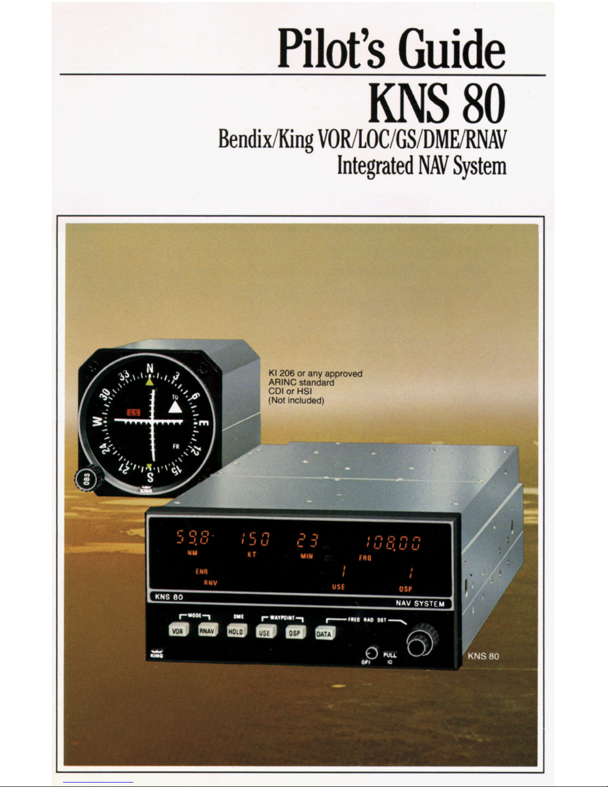
Pilot’s
Guide
KNS
80
Bendi x/King VORILOCIGSIDMERNAV
Integrated
NAV
System
Introduction
.......................................
3
KNS
80
controls, functions and displays
................
RNAV Review
....................................
,
...
What is a waypoint?
..............................
RNAV Geometry
...................................
Linear crosstrack deviation
...................
Variations in along-track distance
while operating in RNAV modes
..................
7
Along Track/Crosstrack error (Chart)
................
KNS
80
System applications
.......................
How
to
use the KNS
80
...............................
IU
Turn
on
..........................................
11
Load waypoint 1 data
.............................
12
Load waypoints
2,3
&
4 data
......................
14
Takeoff and fly
to
waypoint 1
.......................
15
Way point passage
................................
Fly direct to a VORTAC
............................
17
DME
Hold
.......................................
18
RNAV Approach
..................................
19
KNS
80
Specifications
........................
Back Cover
Changeover to next waypoint
......................
,
,
2
KNS
80
c
)<I
206
INTRODUCTION
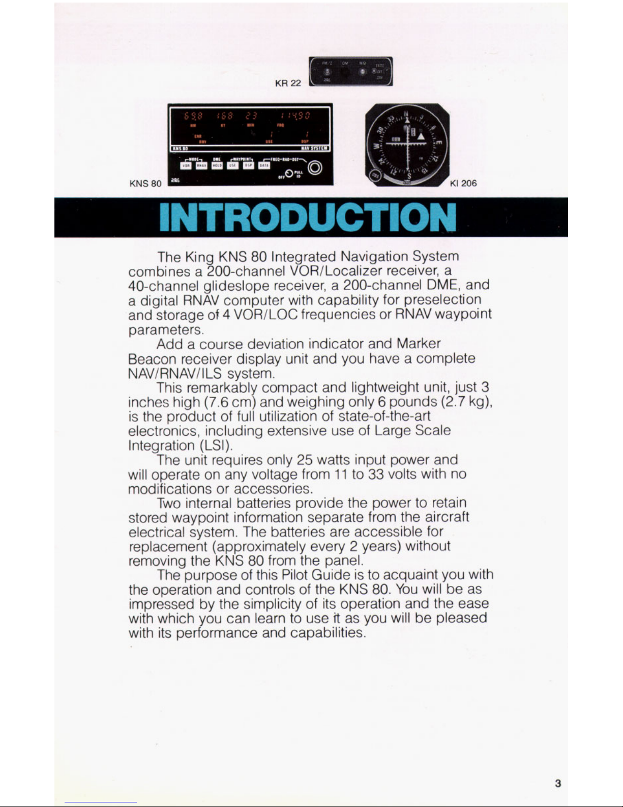
The King KNS
80
Integrated Navigation System
combines a 200-channel VOR/Localizer receiver, a
40-channel glideslope receiver, a 200-channel
DME,
and
a digital RNAV computer with capability for preselection
and storage
of
4 VOR/LOC frequencies or RNAV waypoint
parameters.
Add a course deviation indicator and Marker
Beacon receiver display unit and you have a complete
NAV/RNAV/
I
LS
system.
This remarkably compact and lightweight unit, just
3
inches high
(7.6
cm) and weighing only 6 pounds (2.7 kg),
is the product of full utilization of state-of-the-art
electronics, including extensive use of Large Scale
Integration
(LSI).
The unit requires only 25 watts input power and
will operate on any voltage from
11
to
33
volts with no
modifications or accessories.
Two internal batteries provide the power to retain
stored waypoint information separate from the aircraft
electrical system. The batteries are accessible for
replacement (approximately every 2 years) without
removing the KNS
80
from the panel.
The purpose of this Pilot Guide is to acquaint you with
the operation and controls of the KNS
80.
You
will be as
impressed by the simplicity of its operation and the ease
with which you can learn to use
it
as
you will be pleased
with its performance and capabilities.
3
Controls, functions and displays
9.-
12.
-
I
1.
111111
I-
Battery
compartment
3.
4. 5.
8.
6.
7.
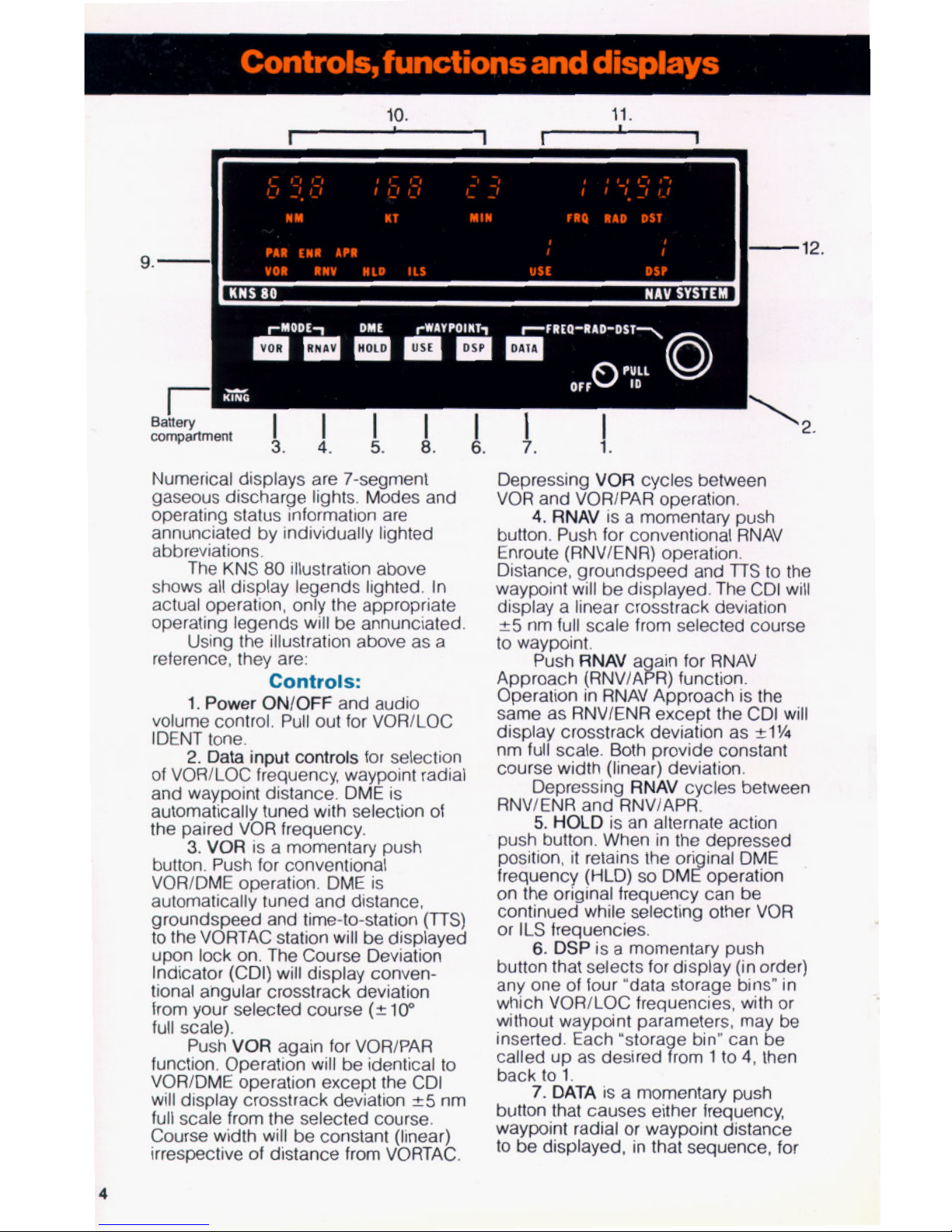
Numerical displays are 7-segment
gaseous discharge lights. Modes and
operating status information are
annunciated by individually lighted
abbreviations.
The KNS
80
illustration above
shows all display legends lighted. In
actual operation, only the appropriate
operating legends will be annunciated.
Using the illustration above as a
reference, they are:
Controls:
1.
Power
ON/OFF and audio
volume control. Pull out for VOR/LOC
IDENT tone.
2. Data input
controls
for selection
of VOR/LOC frequency, waypoint radial
and waypoint distance. DME is
automatically tuned with selection of
the paired VOR frequency.
3.
VOR is a momentary push
button. Push for conventional
VOR/DME operation. DME is
automatically tuned and distance,
groundspeed and time-to-station
(TTS)
to the VORTAC station will be displayed
upon lock on. The Course Deviation
Indicator (CDI) will display conventional angular crosstrack deviation
from your selected course
(210"
full scale).
Push VOR again for VOR/PAR
function. Operation will be identical to
VOR/DME operation except the CDI
will display crosstrack deviation
25
nm
full scale from the selected course.
Course width will be constant (linear)
irrespective of distance from VORTAC.
Depressing VOR cycles between
VOR and VOR/PAR operation.
4.
RNAV is a momentary push
button. Push for conventional RNAV
Enroute (RNV/ENR) operation.
Distance, groundspeed and
TTS
to the
waypoint will be displayed. The CDI
will
display a linear crosstrack deviation
*5
nm full scale from selected course
to waypoint.
Push RNAV a ain for RNAV
Approach (RNV/A!R) function.
Operation in RNAV Approach is the
same as RNV/ENR except the CDI will
display crosstrack deviation as
21%
nm full scale. Both provide constant
course width (linear) deviation.
Depressing RNAV cycles between
RNVlENR and RNVIAPR.
5.
HOLD is an alternate action
push button. When in the depressed
position, it retains the ori inal DME
frequency (HLD)
so
DMZoperation
on the original frequency can be
continued while selecting other VOR
or ILS frequencies.
6.
DSP is a momentary push
button that selects for display (in order)
any one of four "data storage bins" in
which VOR/LOC frequencies, with or
without waypoint parameters, may be
inserted. Each "storage bin" can be
called up as desired from 1 to
4,
then
back
to
1.
7.
DATA is a momentary push
button that causes either frequency,
waypoint radial or waypoint distance
to
be displayed, in that sequence, for
4
the “data storage bin”
(1,
2,
3
or
4)
which is being displayed.
DATA
may be used for either
loading data into
a
“storage bin” or
checking previously loaded data.
8.
USE
is a momentary push
button that selects the VOR/LOC
frequency and waypoint parameters
to
be used for navigation. Pushing
USE
transfers the data displayed (DSP)
to
“in use”
(USE).
To “use” a waypoint, it
must first be displayed by means of
DSP.
It
may then be put into use by
pushing
USE.
This
is
a safety
procedure which requires the display
of a frequency and waypoint
parameters prior
to
actual use.
Anytime
USE
or
DSP
is pushed,
frequency
(FRQ)
will be displayed. This
is a safety feature which forces the
frequency of the facility selected
to
be
displayed before use. Radial (RAD)
and distance (DST) may subsequently
be displayed by use of the
DATA
button:
Displays:
9.
Selected function (VOR,
VOR/PAR, RNVIENR, RNV/APR,
HLD, ILS) are annunciated on the
bottom left side of the display area.
10.
Distance (NM), groundspeed
(KT) and time-to-station (MIN)
to
VORTAC or waypoint are displayed in
the upper left side of the display area.
When the DME is not locked on due
to
no DME signal (VOR facility only; failure
of the DME ground station; range
beyond line of sight) or an airborne
DME failure, dashes will appear in
place of numbers.
11.
The
data
selected by the data
input controls is displayed in the upper
right side of the unit. VOR/LOC
frequency
(FRQ),
waypoint radial
(RAD) and waypoint distance (DST)
are displayed in sequence by
pushing the DATA button. The “data
storage bin”
(1
through
4)
is
selected in
sequence by-pushing the DSP button.
12.
The selected “data storage bin”
in use
(USE)
and the “data storage bin”
being displayed (DSP) are indicated by
the
two
sets of numbers (from 1
to
4)
disdaved in the lower riaht side of the
display area.
-
When the “data storaae bin” “in
use” is different from that dsplayed, the
DSP number
will
flash
to
indicate that
the system is navigating on data
different from that being displayed.
13.
Flag Operation
(CDI
or
HSI)
VOR
or
ILS
Mode:
Invalid
VOR/LOC operation
is
annunciated by
the VOR/LOC flag in the CDI or
HSI.
Glideslope flag indicates invalid GS
information. Dashes in the DME display
annunciate invalid DME.
VOR/PAR
Mode: VOR/LOC flag
in the CDI or
HSI
annunciates VOR
and/or DME invalid. Dashes in the DME
display annunciate DME invalid.
RNAV
Modes: CDI or
HSI
flags
same as VOWPAR Mode. Dashes in
distance display annunciate invalid
DME and/or invalid VOR.
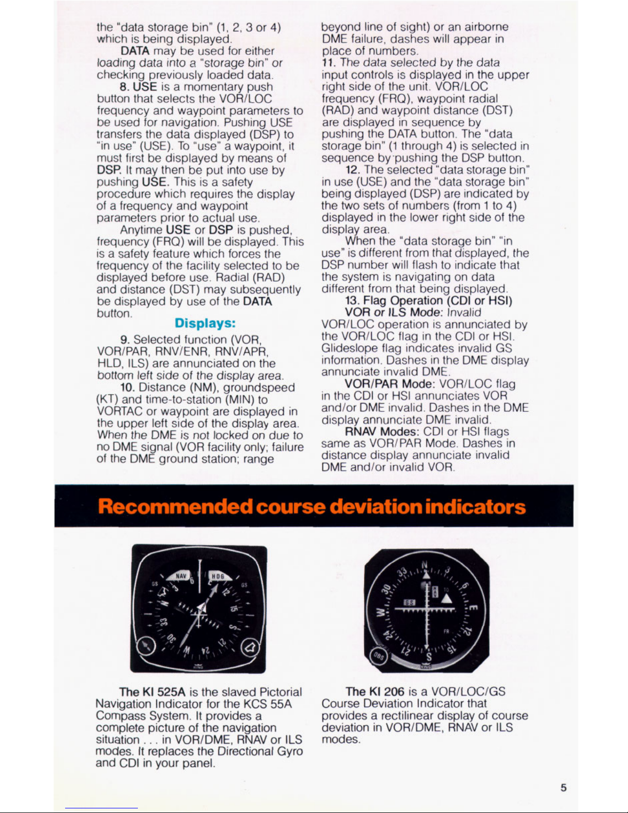
Recommended course deviation indicators
The
KI
525A
is the slaved Pictorial
The
KI
206
is a VOR/LOC/GS
Course Deviation Indicator that
provides
a
rectilinear display of course
deviation in VOWDME, RNAV or ILS
modes.
Navigation Indicator for the KCS 55A
Compass System.
It
provides a
complete picture
of
the navigation
situation
. . .
in VOR/DME, RNAV
or
ILS
modes.
It
replaces the Directional Gyro
and CDI in your panel.
5
RNAV
Review
Area navigation (RNAV) is a method
of point-to-point navigation along any
desired course within the service area
of
a VOR/DME (VORTAC) station, without the
need for flight over the station. This course
is
defined by “waypoints”
What is a waypoint?
A
waypoint is a predetermined
geographic position located within the
service area of a VORlDME station.
It
may
be used for route definition and/or progress
reporting.
A
waypoint is often called a
phantom station because
it
provides the
same navigation information that a “real”
VOR/DME station at that location would
provide.
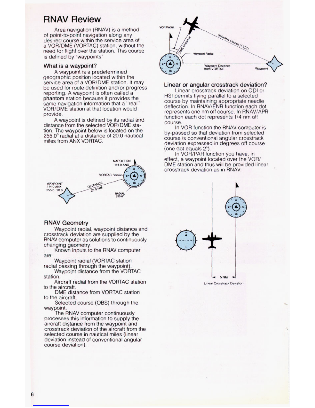
A waypoint is defined by its radial and
distance from the selected VORlDME station. The waypoint below is located on the
255.0”
radial at a distance of
20.0
nautical
miles from
ANX
VORTAC.
WAVPOINT
I
VORTAC Staban
RNAV
Geometry
Waypoint radial, waypoint distance and
crosstrack deviation are supplied by the
RNAV computer as solutions
to
continuously
changing geometry.
Known inputs
to
the RNAV computer
are:
Waypoint radial (VORTAC station
radial passing through the waypoint).
Waypoht distance from the VORTAC
station.
Aircraft radial from the VORTAC station
to
the aircraft.
DME distance from VORTAC station
to the aircraft.
Selected course
(OBS)
through the
waypoint.
The RNAV computer continuously
processes this information
to
supply the
aircraft distance from the waypoint and
crosstrack deviation of the aircraft from the
selected course in nautical miles (linear
deviation instead
of
conventional angular
course deviation).
Linear
or
angular crosstrack deviation?
Linear crosstrack deviation on CDI
or
HSI
permits flying parallel
to
a selected
course by maintaining appropriate needle
deflection In RNAVlENR function each dot
represents one nm off course In RNAVIAPR
function each dot represents
114
nm off
course
In VOR function the RNAV computer
IS
by-passed
so
that deviation from selected
course is conventional angular crosstrack
deviation expressed in degrees off course
(one dot equals
2“)
In VOR/PAR function you have, in
effect, a waypoint located over the VORl
DME station and thus will be provided linear
crosstrack deviation as in RNAV
Linear
Crasstrack
Deviation
6
 Loading...