

Page 1
N
Revision 3 Jun/2004
006-18235-0000
Multi-Function Display
KMD 850
Digital Weather Radar Function
Pilot’s Guide Addendum
B
For Software Version 01/13 or later
Page 2

WARNING
Prior to export of this document, review for export license requirement is needed.
COPYRIGHT NOTICE
©2000-2002, 2004 Honeywell International Inc.
Reproduction of this publication or any portion thereof by any means without
the express written permission of Honeywell International Inc. is prohibited. For
further information contact the Manager, Technical Publications; Honeywell,
One Technology Center, 23500 West 105th Street, Olathe, Kansas 66061.
Telephone: (913) 782-0400.
The information contained in this manual is for reference use only. If
any information contained herein conflicts with similar information
contained in the Airplane Flight Manual Supplement, the information in
the Airplane Flight Manual Supplement shall take precedence.
Page 3

R-1
Revision History
Manual KMD 550/850 Digital Weather Radar Pilot’s Guide
Addendum
Revision 3, June 2004
Part Number 006-18235-0000
Summary
Auto Standby may now be disabled during system configuration
Miscellaneous corrections
Page 4

R-2
Revision History
Manual KMD 550/850 Digital Weather Radar Pilot’s Guide
Addendum
Revision 2, January 2002
Part Number 006-18235-0000
Summary
Complete manual revision
Miscellaneous corrections
Page 5

R-3
Revision History
Manual KMD 550/850 Digital Weather Radar Pilot’s Guide
Addendum
Revision 1, April 2001
Part Number 006-18235-0000
Summary
Added Stabilization function on WX Radar Page
Changed format of TILT field
Radar faults now supported
Added Auto Tilt
Added Manual Gain
Added Sector Scan
Added Automatic Range Limiting
Added 5 nm and 320 nm range settings
Page 6

Revision History
Manual KMD 550/850 Digital Weather Radar Pilot’s Guide
Addendum
Revision 0, October 2000
Part Number 006-18235-0000
Summary
This is the original release of this publication.
R-4
Page 7

Rev 2 Jan/2002
KMD 850 Wx Radar Addendum
Table of Contents
INTRODUCTION . . . . . . . . . . . . . . . . . . . . . . . . . . . . . . . . . . . . . . . . . . . . . . . .1
NORMAL OPERATION . . . . . . . . . . . . . . . . . . . . . . . . . . . . . . . . . . . . . . . . . .2
OPERATIONAL CONTROLS SUMMARY . . . . . . . . . . . . . . . . . . . . . . . .3
WEATHER RADAR OVERVIEW . . . . . . . . . . . . . . . . . . . . . . . . . . . . . . .4
POWER ON . . . . . . . . . . . . . . . . . . . . . . . . . . . . . . . . . . . . . . . . . . . . . . . .5
TEST MODE . . . . . . . . . . . . . . . . . . . . . . . . . . . . . . . . . . . . . . . . . . . . . . .6
ON MODE . . . . . . . . . . . . . . . . . . . . . . . . . . . . . . . . . . . . . . . . . . . . . . . . .7
VERTICAL PROFILE . . . . . . . . . . . . . . . . . . . . . . . . . . . . . . . . . . . . . . . . .8
OVERLAYS . . . . . . . . . . . . . . . . . . . . . . . . . . . . . . . . . . . . . . . . . . . . . . . .8
GROUND MAPPING (MAP) MODE . . . . . . . . . . . . . . . . . . . . . . . . . . . . .9
AUTO STANDBY . . . . . . . . . . . . . . . . . . . . . . . . . . . . . . . . . . . . . . . . . . .9
SET MODE . . . . . . . . . . . . . . . . . . . . . . . . . . . . . . . . . . . . . . . . . . . . . . . .10
STAB ON/OFF . . . . . . . . . . . . . . . . . . . . . . . . . . . . . . . . . . . . . . . . .10
AUTO TILT . . . . . . . . . . . . . . . . . . . . . . . . . . . . . . . . . . . . . . . . . . . .10
MANUAL GAIN . . . . . . . . . . . . . . . . . . . . . . . . . . . . . . . . . . . . . . . . .11
SECTOR SCAN . . . . . . . . . . . . . . . . . . . . . . . . . . . . . . . . . . . . . . . .11
ERROR AND FAULT MESSAGES . . . . . . . . . . . . . . . . . . . . . . . . . . . . . . . .11
i
Page 8

Rev 2 Jan/2002
KMD 850 Wx Radar Addendum
Table of Contents
ii
Intentionally left blank
Page 9

Rev 2 Jan/2002 KMD 850 Wx Radar Addendum
1
INTRODUCTION
The Weather Radar Function of the Bendix/King KMD 850 Multi
Function Display allows for the display and control of several Honeywell
weather radar systems. Weather Radar indicates the presence and
strength of precipitation and is intended to allow the operator to avoid
thunderstorms and associated turbulence.
This Pilot’s Guide Addendum describes the operation of the KMD 850
display for controlling the weather radar sensor. The general operation of
the KMD 850 is described in the other sections of the KMD 550/850
Pilot’s Guide. For detailed information on the proper use and interpretation of the weather radar data please reference the pilot’s guide that was
provided with the weather radar sensor.
Note: The KMD 850 can interface with many different types of radar
and the screen displays may vary compared to the examples
shown in this manual.
The Bendix/King KMD 850 is shown below with the Weather Radar
Page selected.
Page 10

2
Rev 2 Jan/2002
KMD 850 Wx Radar Addendum
NORMAL OPERATION
To display the WX Radar page press the WX button. Note that in some
installations this button may have to be pushed multiple times to switch
between radar and stormscope.
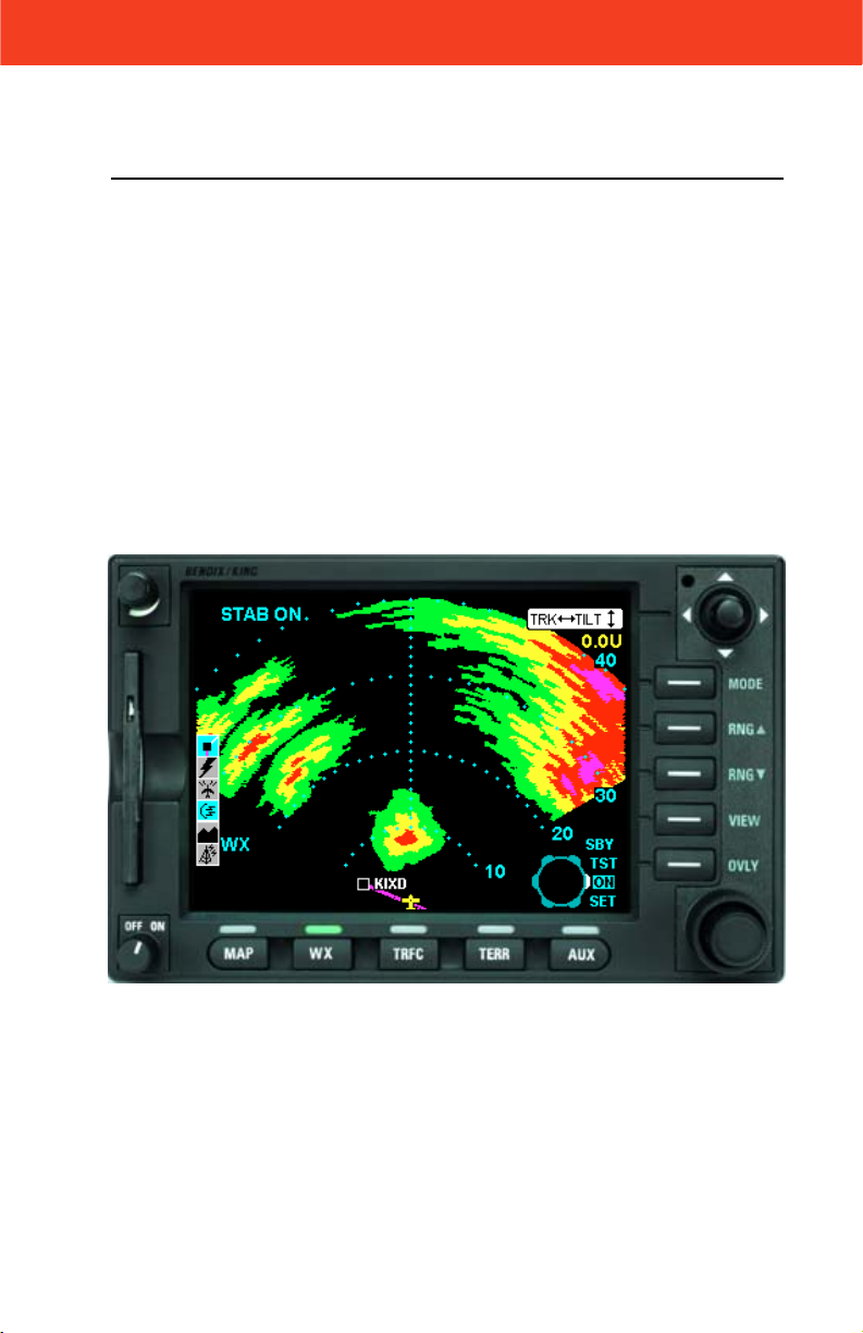
The following illustration defines the data that appears on the WX Radar
Page when the radar is active and the horizontal view is displayed:
56
7
8
4
3
9
10
1 Aircraft Symbol
2 Knob Function Label - Rotating the outer knob selects between
Standby (SBY), Test (TST), ON and SET modes.
3 Display Range Indications
4 Tilt Angle - XX.X Degrees up (U) or down (D).
5 Joystick Function Label - Moving the joystick up and down adjusts
the radar tilt. Moving the joystick left and right adjusts the location of
the yellow track line.
6 Stabilization Indication
7 Track Angle
8 WX Radar Mode Indication - TEST, WX, WX/ARL (Auto Range Limiting
or MAP (Ground Mapping Mode)
9 Available Functions - Displays icons representing data available
(black) and displayed (color)
10 Fault Message Window - See Error and Fault Messages
1
2
Page 11

Rev 2 Jan/2002 KMD 850 Wx Radar Addendum
3
OPERATIONAL CONTROLS SUMMARY
MODE - Toggles between WX, WX/ARL (Auto Range
Limiting) and MAP (ground mapping) modes.
NOTE: Not all weather radar systems support Auto
Range Limiting.
RNG - Range keys clear the display and either
increase or decrease the displayed range.
VIEW - Toggles between Horizontal and Vertical
Profile views.
OVLY - Lit when overlays are available. Allows selection of flight plan, lightning data (if available) or traffic
for overlay on the weather radar display.
Joystick - Moving the joystick up and
down adjusts the antenna tilt up to 15
degrees up or down. Moving the joystick
left or right displays the yellow track line
and moves it left or right of centerline.
Outer Knob - Selects between Standby
(SBY), Test (TST), On and SET mode of
operation.
Inner Knob - Adjusts radar gain. On
most installations this capability is only
available when in ground mapping (MAP)
mode.
Mid-range Gain
Full Gain
Page 12

Rev 2 Jan/2002
KMD 850 Wx Radar Addendum
4
WEATHER RADAR OVERVIEW
The radar display has been calibrated to show five levels of target intensity: Black (level 0), Green (level 1), Yellow (level 2), Red (level 3), and
Magenta (level 4). The meaning of these levels is shown in the following
chart as to their approximate relationship to the Video Integration
Processor (VIP) intensity levels used by the National Weather Service.
These levels are valid only when; (1) the Wx mode is selected; (2) the
displayed returns are within the STC range of the radar; (3) the returns
are beam filling; (4) there are no intervening radar returns.
NOTE: Refer to your Weather Radar Pilot’s Guide for complete
details on the the proper use of weather radar.
Radar Display and Thunderstorm Levels
Versus Rainfall Rates
Video Integrated Processor (VIP)
Display
Level
4
(Magenta)
Storm
In./Hr. In./Hr.mm/Hr.
mm/Hr.
Greater
Than
50
Category
Greater
Than
2
CategorizationsRainfall Rate
VIP
Level
6Extreme
Rainfall Rate
Greater
Than
125
Severe turbulence,
large hail, lightning,
5
extensive wind gust,
and turbulence.
Severe turbulence,
lightning,organized
2-550-1255Intense
wind gusts, hail
likely.
Remarks
1-225-504
0.5-112-253Strong
Severe turbulence
likely, lightning.
Severe turbulence,
possible lightning.
Light to moderate
turbulence is
possible with
lightning.
Light to moderate
turbulence is
possible with
lightning.
3
(Red)
2
(Yellow)
1
(Green)
0
(Black)
12-50
4-12
1-4
Less
Than
1
0.5-2
0.17-0.5
0.04-0.17
Less
Than
0.04
Very
Strong
0.1-0.52.5-122Moderate
.01-0.10.25-2.51Weak
Page 13

Rev 2 Jan/2002 KMD 850 Wx Radar Addendum
5
POWER ON
When the KMD 850 is initially turned on and the WX key is pressed to
select the WX Radar page the following screen will be displayed:
This indicates that the weather radar sensor has been energized, is in
standby mode, and is communicating properly with the KMD 850 MFD.
While in standby the radar is not transmitting. The radar icon on the icon
bar shows a color radar dish with no energy waves being radiated from
it.
NOTE: The On/Off control of the KMD 850 does not control primary
power to the radar. The only way to remove primary power from
the radar is to pull the radar circuit breaker.
Page 14

6
Rev 2 Jan/2002
KMD 850 Wx Radar Addendum
TEST MODE
Rotating the outer knob one click clockwise will put the radar in test
mode which should display a test pattern similar to the following:
The display should show 4 bands of color with a green band from 10 to
20 miles, a yellow band from 20 to 30 miles, a red band from 30 to 40
miles, and a magenta band from 40 to 50 miles. The RNG keys can be
used to adjust the range scale that is shown.
Pressing the VIEW key will display a test pattern in vertical profile view
similar to the following:
Page 15

Rev 2 Jan/2002 KMD 850 Wx Radar Addendum
7
ON MODE
Rotating the outer knob one more click clockwise to the ON position
causes the radar to begin actively transmitting and scanning. The radar
icon on the icon bar now indicates energy being transmitted by the radar
dish.
NOTE: Whenever the weather radar icon is shown as then the
radar is transmitting and appropriate precautions should be taken.
To better paint the storm we adjust the tilt angle by moving the joystick
up and down to the appropriate value as described by the weather radar
pilot’s guide. This example shows a tilt of 7 degrees down has been
selected. The tilt angle is shown in the top right corner of the display.
To determine what direction the storm cells are off the nose of the airplane we adjust location of the yellow track line by moving the joystick
left or right. This example shows the track line pointing to one of the
heaviest storm cells that is 45 degrees to the right. The track line angle is
shown at the top left corner of the display.
Page 16

8
Rev 3 Jun/2004
KMD 850 Wx Radar Addendum
VERTICAL PROFILE
If the radar has vertical profile capability then the track line is also used
to select the area of the storm to observe vertically. Once the track line is
in the proper location then pushing the VIEW key will switch to vertical
profile view as shown. Pressing the VIEW key again will switch back to
horizontal profile view.
If the azimuth track angle is changed while the vertical profile view is
active, “WAIT” will be displayed just below the track angle indication (in
this case R 45) until the radar repositions the antenna.
OVERLAYS
The flightplan, lightning strikes and traffic can be overlaid on top of the
radar by pressing the OVLY key and using the appropriate softkeys to
turn the overlays on.
NOTE: The flightplan can only be overlaid on the radar if a heading
source is available.
Page 17

Rev 3 Jun/2004 KMD 850 Wx Radar Addendum
9
GROUND MAPPING (MAP) MODE
The radar can be put into Ground Mapping mode by pressing the MODE
key. Ground Mapping Mode is indicated by the word MAP in the lower
left corner of the display.
In Ground Mapping mode the inner knob controls the radar gain. The
present setting is indicated by the white arc on the knob icon.
AUTO STANDBY
To help reduce the possibility of leaving the radar in the ON mode after
landing, the KMD 850 has an Auto Standby capability. The KMD 850 will
automatically put the radar into Standby when the aircraft’s ground
speed goes below 30 knots. The message “WX Alert - Radar switched
to STANDBY mode.” will pop up on any page when this occurs as
shown in the following figure.
Note: This feature may be enabled or dis-
abled during system configuration only by a qualified service technician.
Page 18

10
Rev 2 Jan/2002
KMD 850 Wx Radar Addendum
SET MODE
When the Outer Control
Knob is placed in the SET
position, a display similar to
Figure 1 will be displayed.
These Soft Keys allow
access to the functions
shown. Not all these functions will be available in all
weather radar installations.
STAB ON/OFF
Pressing the STAB ON/OFF Key will toggle radar antenna stabilization
on or off, which is reflected in the upper left of the display.
NOTE: The RDS 84 and RDS 86 radars do not support manual stabilization ON/OFF control and will ignore the command from the KMD
850. The annunciation in the top left of the display will always
reflect the present stabilization status of the radar system.
AUTO TILT
Pressing the AUTO TILT
Key will toggle between
manual and automatic radar
antenna tilt control. When in
manual mode, the tilt display
fields in the upper right
corner of the display will be
similar to Figure 1. When in
automatic mode, the fields
will be similar to that shown
in Figure 2, with an “A” in
front of the tilt value to indicate Auto Tilt Mode.
Manual Tilt Mode
In manual mode the radar antenna tilt angle is adjusted by moving the
Joystick up or down. The antenna tilt may be adjusted up or down 15°.
See the radar system operator’s manual for proper tilt management.
Figure 1
Figure 2
Page 19

Rev 2 Jan/2002 KMD 850 Wx Radar Addendum
11
Auto Tilt Mode
Allows the antenna position to be automatically adjusted by radar system
to maintain a common beam intercept point with the earth e.g. if the last
10% of the display is ground returns, then during ascent or decent the
antenna tilt is automatically changed to maintain ground returns on 10%
of the display.
MANUAL GAIN
Pressing the MANUAL GAIN Key will toggle between manual and automatic gain control in the WX mode. This feature must be enabled within
the radar system’s configuration to be functional here.
SECTOR SCAN
Pressing the SECTOR
SCAN Key will toggle Sector
Scan on or off as shown in
Figure 3. Not all radar systems support this feature.
In rapidly changing areas of
weather, the radar scan
updates can be made faster
by isolating the desired
viewing area in a 60° sector.
To accomplish this turn
Sector Scan on as discussed
in the previous paragraph. Using the Joystick, position the Track Line
over the desired viewing area. The radar will now update weather only
within this 60° sector.
Figure 3
Page 20

12
Rev 2 Jan/2002
KMD 850 Wx Radar Addendum
ERROR AND FAULT MESSAGES
If the KMD 850 is not
receiving any data from the
weather radar sensor, the
following message will be
displayed and the radar icon
will be shown with a red
circle and slash through it.
This may indicate that the
radar is not receiving primary
power (e.g. an open circuit
breaker), a problem in the
wiring connection between
the radar and the MFD display, or a faulty radar.
Any self test failures reported
by the radar such as TxFLT
will be displayed in the Fault
Message Window in the
bottom left corner of the display.
The following table defines the possible fault messages displayed in the
Fault Message Window.
Page 21

N
Honeywell International Inc.
One Technology Center
23500 West 105th Street
Olathe, KS 66061
Telephone (913) 782-0400
FAX 913-712-1302
©2000 - 2002, 2004 Honeywell International Inc.
All rights reserved.
006-18235-0000 Printed in U.S.A.
Revision 3 Jun/2004
 Loading...