

Page 1
B
Multi-Function Display
Pilot’s Guide
KMD 550/850
Revision 9 Feb/2009
006-18222-0000
N
For Software Version 02/02 and later
Page 2

The information contained in this manual is for reference use only. If
any information contained herein conflicts with similar information
contained in the Airplane Flight Manual Supplement, the information in
the Airplane Flight Manual Supplement shall take precedence.
Covered by US Pat. 6512975
WARNING
Prior to export of this document, review for export license requirement is
needed.
COPYRIGHT NOTICE
Copyright ©2000 - 2005, 2007, 2009 Honeywell International Inc.
All rights reserved.
Reproduction of this publication or any portion thereof by any means without
the express written permission of Honeywell International Inc. is prohibited.
For further information contact the Manager, Technical Publications;
Honeywell International Inc.; One Technology Center; 23500 West 105th
Street; Olathe, Kansas 66061. Telephone: (913) 712-0400.
Page 3

R-1
Revision History
Manual KMD 550/850 Pilot’s Guide
Revision 9, February 2009
Part Number 006-18222-0000
Summary
Added XM products:
Precipitation Type (at Surface)
Freezing Levels
Winds Aloft
Translated Metars
Temporary Flight Restrictions (TFR’s)
Page 4

R-2
Revision History
Manual KMD 550/850 Pilot’s Guide
Revision 8, March 2007
Part Number 006-18222-0000
Summary
Added XM functionality
Added DTK readout on Map page
Updated SUA boundary labels
Page 5

R-3
Revision History
Manual KMD 550/850 Pilot’s Guide
Revision 7, September 2005
Part Number 006-18222-0000
Summary
Changed Stormscope®to registered trademark
Updated displays
Miscellaneous corrections
Page 6

R-4
Revision History
Manual KMD 550/850 Pilot’s Guide
Revision 6, June 2004
Part Number 006-18222-0000
Summary
Changed lightning symbols to white
Changed airspace classifications
Changed display color for Danger, Prohibited and Restricted
Airspace
Added black border to active flight plan leg display
Updated startup pages
Miscellaneous corrections
Page 7

R-5
Revision History
Manual KMD 550/850 Pilot’s Guide
Revision 5, January 2003
Part Number 006-18222-0000
Summary
Complete manual revision
Page 8

R-6
Revision History
Manual KMD 550/850 Pilot’s Guide
Revision 4, January 2003
Part Number 006-18222-0000
Summary
Complete manual revision
Page 9

R-7
Revision History
Manual KMD 550/850 Pilot’s Guide
Revision 3, May 2002
Part Number 006-18222-0000
Summary
Complete manual revision
Page 10

R-8
Revision History
Manual KMD 550/850 Pilot’s Guide
Revision 2, November 2001
Part Number 006-18222-0000
Summary
Improved display of traffic overlay on the Map Page
Small Traffic Window is no longer displayed when the Map Page is in
the north-up orientation.
The Map Setup Page may be configured to be inaccessible to the .
operator
Inner and outer knobs are enabled to select airport information from
the Map Page by entering identifier, name or city
Page 11

R-9
Revision History
Manual KMD 550/850 Pilot’s Guide
Revision 1, April 2001
Part Number 006-18222-0000
Summary
Revised Database Warning Page
Added GCO frequencies to Airport MORE INFO Window
Added Heliroutes and Helipads to Map Page
Airplane symbol now oriented to heading on Map Page
Added traffic display functions
Changed lightning symbols and Function Display Icon for strikes with
in 25 nm
Corrected miscellaneous errors
Page 12

R-10
Revision History
Manual KMD 550/850 Pilot’s Guide
Revision 0, October 2000
Part Number 006-18222-0000
Summary
This is the original release of this publication.
Page 13

INTRODUCTION . . . . . . . . . . . . . . . . . . . . . . . . . . . . . . . . . . . . . . . . . . . . . . .1
GENERAL INFORMATION . . . . . . . . . . . . . . . . . . . . . . . . . . . . . . . . . . . . .3
FUNCTION SELECT KEYS . . . . . . . . . . . . . . . . . . . . . . . . . . . . . . . . . . .4
POWER KEYS . . . . . . . . . . . . . . . . . . . . . . . . . . . . . . . . . . . . . . . . . . . .4
POWER LABELS . . . . . . . . . . . . . . . . . . . . . . . . . . . . . . . . . . . . . . . . . .4
SOFT LABELS . . . . . . . . . . . . . . . . . . . . . . . . . . . . . . . . . . . . . . . . . . . .5
JOYSTICK . . . . . . . . . . . . . . . . . . . . . . . . . . . . . . . . . . . . . . . . . . . . . . .5
CONTROL KNOB . . . . . . . . . . . . . . . . . . . . . . . . . . . . . . . . . . . . . . . . . .5
FAULT INDICATOR . . . . . . . . . . . . . . . . . . . . . . . . . . . . . . . . . . . . . . . . .5
STORMSCOPE®OPTION . . . . . . . . . . . . . . . . . . . . . . . . . . . . . . . . . . . .7
OBSTACLE LABELS . . . . . . . . . . . . . . . . . . . . . . . . . . . . . . . . . . . . . . . .7
MAP TOPOGRAPHIC AND URBAN AREAS DISPLAY . . . . . . . . . . . . . . .7
STARTUP DISPLAY . . . . . . . . . . . . . . . . . . . . . . . . . . . . . . . . . . . . . . . .8
POP-UP HELP DISPLAYS . . . . . . . . . . . . . . . . . . . . . . . . . . . . . . . . . . .8
OPERATION . . . . . . . . . . . . . . . . . . . . . . . . . . . . . . . . . . . . . . . . . . . . . . . .9
SELECTING A MAP DISPLAY . . . . . . . . . . . . . . . . . . . . . . . . . . . . . . . . .9
USING THE MAP . . . . . . . . . . . . . . . . . . . . . . . . . . . . . . . . . . . . . . . . . .9
Data Interrogation . . . . . . . . . . . . . . . . . . . . . . . . . . . . . . . . . . . . . .11
Airport Information . . . . . . . . . . . . . . . . . . . . . . . . . . . . . . . . . . . . .12
Navaid Information . . . . . . . . . . . . . . . . . . . . . . . . . . . . . . . . . . . . .16
General Icon Information . . . . . . . . . . . . . . . . . . . . . . . . . . . . . . . . .16
Airspace Interrogation . . . . . . . . . . . . . . . . . . . . . . . . . . . . . . . . . . .17
Display Flight Plan Data . . . . . . . . . . . . . . . . . . . . . . . . . . . . . . . . . .17
OVERLAYING DATA . . . . . . . . . . . . . . . . . . . . . . . . . . . . . . . . . . . . . . .18
DISPLAYING WEATHER RADAR (KMD 850 ONLY), STORMSCOPE
®
OR FLIGHT INFORMATION SERVICES . . . . . . . . . . . . . . . . . . . . . . . . .19
DISPLAYING TRAFFIC . . . . . . . . . . . . . . . . . . . . . . . . . . . . . . . . . . . . .19
SELECTING ENHANCED GROUND PROXIMITY WARNING SYSTEM . .19
VIDEO DISPLAY . . . . . . . . . . . . . . . . . . . . . . . . . . . . . . . . . . . . . . . . . .19
Table of Contents
KMD 550/850 Pilot's Guide
Rev 9 Feb/2009
i
Page 14

SYSTEM SETUP . . . . . . . . . . . . . . . . . . . . . . . . . . . . . . . . . . . . . . . . . . . .21
INTRODUCTION . . . . . . . . . . . . . . . . . . . . . . . . . . . . . . . . . . . . . . . . . .21
MAP SETUP . . . . . . . . . . . . . . . . . . . . . . . . . . . . . . . . . . . . . . . . . . . . .21
TEMPORARY FLIGHT RESTRICTIONS (TFR) . . . . . . . . . . . . . . . . . . . .23
WX-500 STORMSCOPE®SETUP . . . . . . . . . . . . . . . . . . . . . . . . . . . . .25
DATA CARDS . . . . . . . . . . . . . . . . . . . . . . . . . . . . . . . . . . . . . . . . . . . . . .27
DATA AREAS . . . . . . . . . . . . . . . . . . . . . . . . . . . . . . . . . . . . . . . . . . . .27
CHANGING THE DATA CARD . . . . . . . . . . . . . . . . . . . . . . . . . . . . . . . .28
DATABASE INFORMATION . . . . . . . . . . . . . . . . . . . . . . . . . . . . . . . . .28
DATABASE CYCLE INFORMATION . . . . . . . . . . . . . . . . . . . . . . . . . . . .28
DEFINITIONS, ACRONYMS AND ABBREVIATIONS . . . . . . . . . . . . . . . . .29
DEFINITIONS . . . . . . . . . . . . . . . . . . . . . . . . . . . . . . . . . . . . . . . . . . . .29
ACRONYMS AND ABBREVIATIONS . . . . . . . . . . . . . . . . . . . . . . . . . . .30
WX-500 STORMSCOPE®OPERATION . . . . . . . . . . . . . . . . . . . . . . . . . .35
INTRODUCTION . . . . . . . . . . . . . . . . . . . . . . . . . . . . . . . . . . . . . . . . . .35
FUNCTIONAL DESCRIPTION . . . . . . . . . . . . . . . . . . . . . . . . . . . . . . . .35
OPERATION . . . . . . . . . . . . . . . . . . . . . . . . . . . . . . . . . . . . . . . . . . . . .35
Selecting Stormscope®or Weather Radar . . . . . . . . . . . . . . . . . . .35
Power-up . . . . . . . . . . . . . . . . . . . . . . . . . . . . . . . . . . . . . . . . . . . . .36
Heading Stabilization . . . . . . . . . . . . . . . . . . . . . . . . . . . . . . . . . . . .36
Clear All Discharge Points . . . . . . . . . . . . . . . . . . . . . . . . . . . . . . . .36
Switch Between Weather Views . . . . . . . . . . . . . . . . . . . . . . . . . . . .36
Switch Between Display Modes . . . . . . . . . . . . . . . . . . . . . . . . . . . .37
Cell Display Mode . . . . . . . . . . . . . . . . . . . . . . . . . . . . . . . . . . . .37
Strike Display Mode . . . . . . . . . . . . . . . . . . . . . . . . . . . . . . . . . . .38
Changing Display Range . . . . . . . . . . . . . . . . . . . . . . . . . . . . . . . . .38
Operation in Stormscope
®
Mode with Flight Plan Overlay . . . . . . .39
Operation in Map Display . . . . . . . . . . . . . . . . . . . . . . . . . . . . . . . . .39
WX-1000E STORMSCOPE®OPERATION . . . . . . . . . . . . . . . . . . . . . . . .41
Table of Contents
ii
KMD 550/850 Pilot's Guide
Rev 9 Feb/2009
Page 15

INTRODUCTION . . . . . . . . . . . . . . . . . . . . . . . . . . . . . . . . . . . . . . . . . .41
FUNCTIONAL DESCRIPTION . . . . . . . . . . . . . . . . . . . . . . . . . . . . . . . .41
OPERATION . . . . . . . . . . . . . . . . . . . . . . . . . . . . . . . . . . . . . . . . . . . . .41
Selecting Stormscope®or Weather Radar . . . . . . . . . . . . . . . . . . .42
Power-up . . . . . . . . . . . . . . . . . . . . . . . . . . . . . . . . . . . . . . . . . . . . .42
Switch Between Weather Views . . . . . . . . . . . . . . . . . . . . . . . . . . . .42
Changing Display Range . . . . . . . . . . . . . . . . . . . . . . . . . . . . . . . . .42
Operation in Stormscope®Mode with Flight Plan Overlay . . . . . . .43
Operation in Map Display . . . . . . . . . . . . . . . . . . . . . . . . . . . . . . . . .43
APPENDIX A, DISPLAY ICONS . . . . . . . . . . . . . . . . . . . . . . . . . . . . . . . .A-1
Table of Contents
KMD 550/850 Pilot's Guide
Rev 9 Feb/2009
iii
Page 16

Table of Contents
iv
KMD 550/850 Pilot's Guide
Rev 9 Feb/2009
Intentionally left blank
Page 17

INTRODUCTION
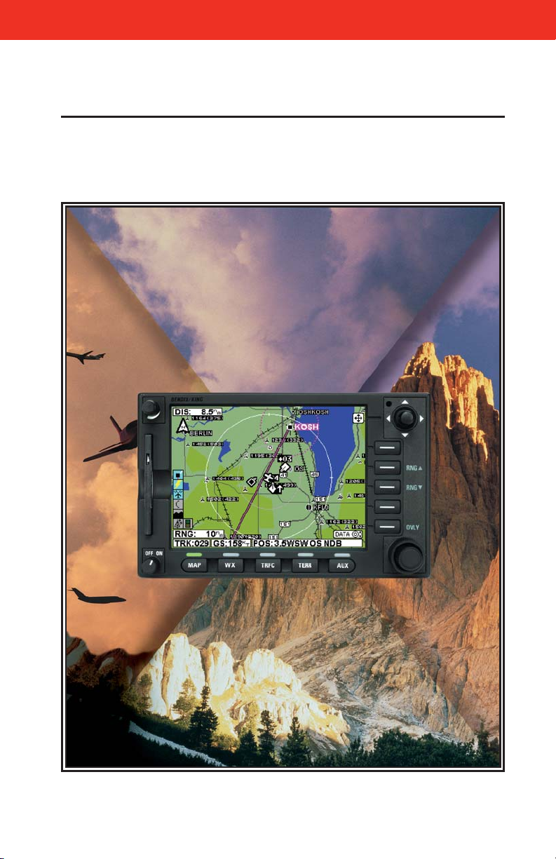
All of us at Honeywell congratulate you on choosing this product. You
are now the owner of one of the most sophisticated yet simple-to-use
multifunction displays available today. We understand you probably
can’t wait to see it in action but before you try to use it please take the
time to read through this manual and understand its many interesting
and useful features. Time spent in familiarizing yourself with your new
KMD 550/850 unit will be more than repaid by trouble-free operation
later, and more importantly safe and accurate navigation.
We have made the operation of this unit as intuitive as possible through
the use of Power Keys and on-screen help, thus reducing pilots’ dependence on the manual. You should very quickly find that handling it efficiently and expertly becomes second nature to you. Don’t be afraid to
experiment. No matter which key you activate, your unit will not be damaged. If you do get into a mess, simply switch off and back on again to
reset all functions. We must mention just one word of caution. Never
remove the database card while the unit is switched on and never
attempt to switch the unit on when there is no database card
installed.
We thank you for your decision to purchase a KMD 550/850 and wish
you many happy and safe hours flying.
Whenever you are using the unit for navigation in the air you should treat
it as a supplemental display system. You should always carefully compare indications from your KMD 550/850 unit with the information available from all other navigation sources including GPS, NDBs, VORs,
DMEs, visual sightings, charts, etc. For safety, any discrepancies
observed should be resolved immediately.
This equipment is not a replacement for your chart. It is intended as an
aid to navigation only. The database within the equipment has been
compiled from the latest official information available, and although
every care has been taken in the compilation, the manufacturers will not
be held responsible for any inaccuracy or omissions therein. NEVER
USE THE TERRAIN DISPLAYED ON THIS EQUIPMENT AS YOUR
SOLE REFERENCE FOR TERRAIN AVOIDANCE.
Rev 9 Feb/2009 KMD 550/850 Pilot's Guide
1
Introduction
Page 18

2
Rev 9 Feb/2009
KMD 550/850 Pilot's Guide
Introduction
Intentionally left blank
Page 19
Rev 9 Feb/2009 KMD 550/850 Pilot's Guide
3
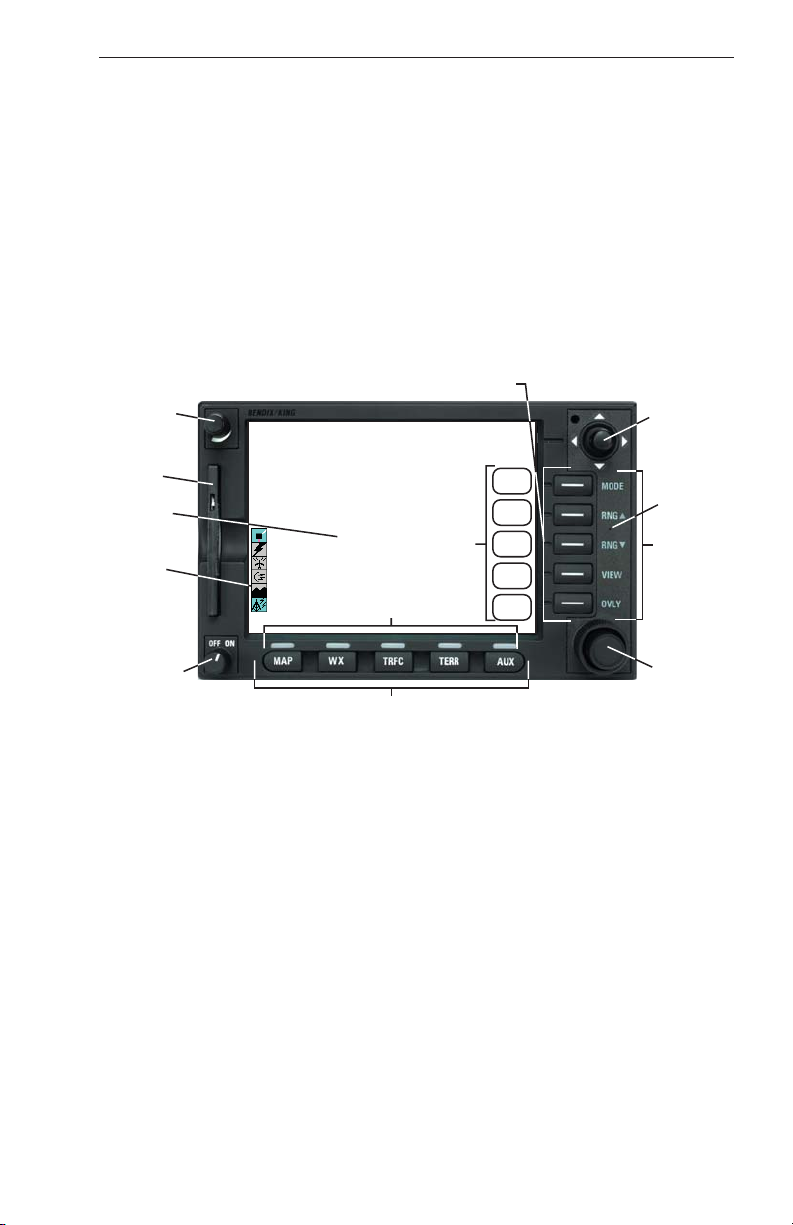
GENERAL INFORMATION
This section of the manual provides an overview of the software architecture and display presentation of the KMD 550/850 Multifunction Display.
This manual also provides an explanation of each of the individual displays that the KMD 550/850 unit presents.
The operating system of the Bendix/King KMD 550/850 keeps to a minimum the number of key presses necessary to activate the various functions, especially those most frequently used in the air. The provision of a
joystick makes it considerably easier to operate the unit and allows for
fast and efficient access to most functions.
1. Brightness Control
2. Data Card
3. Display
4. Available Functions Legend
5. On/Off Control
6. Function Select Indicators
7. Function Select Keys
8. Control Knobs (Inner and Outer Knob)
9. Power Labels
10. Soft Labels
11. Joystick
12. Power Keys
13. Fault Indicator
See Appendix A for a description of Functions Legend and map display
icons.
General Information
12
1
2
3
10
4
6
11
13
F
9
5
8
7
Page 20

4
Rev 9 Feb/2009
KMD 550/850 Pilot's Guide
FUNCTION SELECT KEYS
These keys are used to select available data sources (as indicated on
the key) for display on the LCD. When a function key is pressed, the
annunciator above it will illuminate to show that this function is presently
being displayed. Pressing the same Function Select Key multiple times
will sequence through the available pages associated with that function.
The following diagram shows the available pages under each function.
Note that not all pages will be available in all installations.
POWER KEYS
These five keys are used to manipulate the page being displayed. Their
present functionality can be indicated by the use of Soft Labels on the
left side of the key or Power Labels on the right side of the key.
POWER LABELS
When the Power Label is illuminated on the right side of the key, that
key’s function is dedicated to the function described by the label and that
function is active. The following is a list of the dedicated functions:
MODE- Pressing this key will sequence through all available modes
associated with the displayed page.
RNGΔ- Pressing this key will increase the range scale one level on
the displayed page. Range scales on other pages will not
be affected.
RNG∇- Pressing this key will decrease the range scale one level on
the displayed page. Range scales on other pages will not
be affected.
VIEW- Pressing this key will sequence through the available views
associated with the displayed page.
General Information
WX TRFC TERR AUXMAP
Topo On
Map
Topo Off
Map
WX Radar*
Stormscope
Datalink Wx
Graphical
Products
Datalink Wx
Textual
Products
TAS/TCAS/TIS
* KMD 850 Only
EGPWS
Setup Pages
External
NTSC Video
Page 21

Rev 9 Feb/2009 KMD 550/850 Pilot's Guide
5
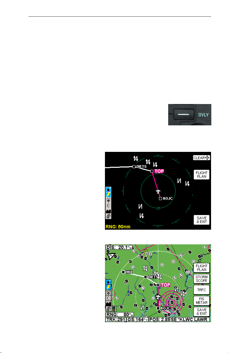
OVLY- Pressing the Overlay Key allows data from more than one
source to be displayed simultaneously on the display. Soft
Labels will indicate which data sources are available for
overlay.
SOFT LABELS
Soft Labels are located to the left of the Power Keys in the LCD area.
The description indicated in the label describes the key’s present function related to the displayed page. Whenever a new function is selected,
by pressing a key with a Soft Label, a new display is shown along with its
new key labels. This capability of displaying Soft Labels that are only
applicable to a particular screen is referred to as ‘Soft Keying’, and
allows one key to perform multiple functions without the complications of
multiple key presses on a conventional keypad.
JOYSTICK
This is a pointing device which moves a mouse-like pointer around the
display. It is primarily used for pointing at items on the map for further
information and for measuring range and bearing to specific points.
When the WX Radar function is selected, the joystick controls antenna
tilt angle and track. Data link weather also uses the joystick to perform
product display selection. It is also used to modify configuration settings
on the AUX setup pages.
CONTROL KNOB
The inner and outer Control Knobs, located in the lower right of the unit,
have various functions as indicated by a soft label when active. For
example, if the weather (WX) Function Select Key is pressed, the inner
knob may control the gain on the weather radar. The outer knob will act
as the radar function selector for ON, Standby (SBY) and Test (TST).
Data link weather also uses the joystick to do product display selection.
FAULT INDICATOR
The Fault Indicator is located between the Range buttons. If this tiny “F”
is illuminated, a system hardware problem is exists. This could be
caused by the unit failing a self test or an improper installation configuration.
If the Fault Indicator appears, cycle the unit power. If the fault re-occurs,
the unit needs to be taken to an authorized service center to correct the
configuration or repair the unit.
General Information
Page 22

6
Rev 9 Feb/2009
KMD 550/850 Pilot's Guide
NOTE:
IF THE FAULT INDICATOR IS LIT, ALL DISPLAYED DATA SHOULD
BE TREATED AS SUSPECT AND CROSS-CHECKED FOR ACCURACY BEFORE USE.
The following illustration describes the data that appears on the Map
Display Page.
General Information
16
15
14
13 12
11
17
10
18
1
6
2 5
1 Display Range - RNG:####nm
2 Current Track - TRK:###
3 Current Ground Speed - GS:###kt
4 Distance to Pointer - PDIS: ###.#nm
5 Position Readout - Current aircraft position
6 Control Knob Label - Indicates Control Knob is active for data entry
7 Bearing to Pointer - PBRG: ###
8 MORE INFO Soft Label
9 Range Rings - Outer ring radius is selected range, inner ring radius is
one half the selected range
10 RESET STICK Soft Label
11 Joystick Label
12 Lightning Overlay
13 Desired Track - Active leg oriented to magnetic desired track (magenta)
14 GPS Flight Plan Overlay - Current GPS flight plan
15 Aircraft Symbol - Indicates present position. Stylized airplane when
heading input is present, a plus symbol with no heading.
16 Distance to Waypoint - DIS:###.#nm
17 North Pointer
18 Available Functions - Displays icons representing data available (black)
and displayed (color)
3
4
9
8
7
Page 23

Rev 9 Feb/2009 KMD 550/850 Pilot's Guide
7
STORMSCOPE®OPTION
The KMD 550/850 has the ability to interface and control an L3 WX-500
or WX-1000E Stormscope®‘black box’ thunder storm sensor. When the
Stormscope®interface is on and the overlay is enabled, lightning icons
will also appear on the display.
OBSTACLE LABELS
Obstacles are labeled with two numbers. The first number is the height
of the obstacle in FEET ABOVE MSL. The second number (in brackets)
is the height of the obstacle in FEET AGL.
MAP TOPOGRAPHIC AND URBAN AREAS DISPLAY
On all TOPO ON map displays, the land is shaded to show rising ground
in seven elevation levels similar to those seen on a paper chart. In addition, all built up or urban areas are shaded light gray. Oceans, rivers and
lakes are blue. The levels and colors for the terrain shading vary with the
data card installed and are depicted as follows:
TERRAIN
Color Atlantic (MSL) Americas & Pacific (MSL)
Light Green 0 - 499 feet 0 - 999 feet
Medium Green 500 - 999 feet 1000 - 1999 feet
Dark Green 1000 -1999 feet 2000 - 2999 feet
Light Brown 2000 - 2999 feet 3000 - 4999 feet
Medium Brown 3000 - 4999 feet 5000 - 8999 feet
Dark Brown 5000 - 8999 feet 9000 - 12999 feet
Dark Red 9000 feet and above 13000 feet and above
A color key can be displayed on the TOPO ON Map display. Move the
joystick pointer to any terrain area away from icons or control areas and
press the MORE INFO Key.
General Information
Page 24
8
Rev 9 Feb/2009
KMD 550/850 Pilot's Guide
CAUTION
NEVER USE THE TOPOGRAPHIC ELEVATION DISPLAYED ON
THIS EQUIPMENT AS YOUR SOLE REFERENCE FOR TERRAIN
AVOIDANCE.
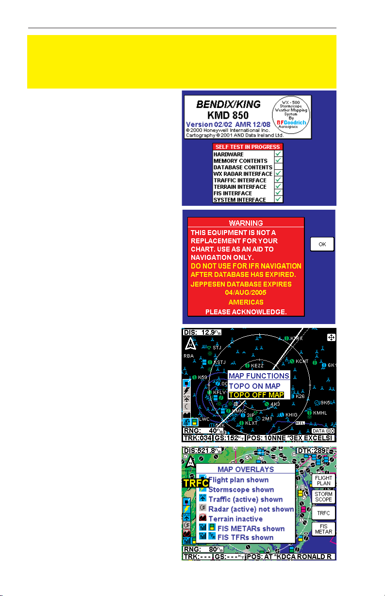
STARTUP DISPLAY
This display will be seen after
power-up. The Stormscope®logo
will only be present if a WX-500
Stormscope®is installed and
enabled. Notice the self test
results are also displayed.
Pressing the OK Soft Key will show
the next display. The expiration
date of the Jeppesen database
must be acknowledged by again
pressing the OK soft key.
POP-UP HELP
DISPLAYS
Pop-up status displays are shown
if a Function Key or available
Power Key is pressed and held for
longer than 2 seconds. These can
help provide a reference for monitoring the status of selected functions and overlays. The first
example is a MAP Function Select
Key pop-up. Second is the pop-up
displayed when pressing and
holding the OVLY Key.
General Information
Page 25

Rev 9 Feb/2009 KMD 550/850 Pilot's Guide
9
OPERATION
SELECTING A MAP DISPLAY
Press the MAP Function
Select Key to toggle between
TOPO ON or TOPO OFF.
With TOPO ON classes of
data are displayed as a specific color. With TOPO OFF
all cartographic data is automatically removed and the
Jeppesen Nav Data is presented on a black background.
A color key can be displayed
on the Map display when in
TOPO ON mode. Move the
joystick pointer to any terrain
area away from icons or control areas and press the
MORE INFO Key. A color
key will be displayed as in
Figure 3. To exit, clear by
moving the joystick and
press the RESET STICK
Key.
NOTE: The number displayed in the colored boxes
of the legend in Figure 3 represent the lowest limit of the
altitude range for that color.
Refer to the chart shown previously in MAP TOPOGRAPHIC AND URBAN
AREAS DISPLAY to determine the altitude range for
each color.
USING THE MAP
After power-up, the map will
initially be displayed at a
range setting of 80nm.
Operation
Figure 1 - TOPO ON
Figure 2 - TOPO OFF
Figure 3
Page 26

10
Rev 9 Feb/2009
KMD 550/850 Pilot's Guide
Operation
If there is no valid GPS or FMS position fix data available, the words NO
EXTERNAL POSITION DATA will be shown across the center of the
display in a box. If the fix is lost at any time during normal operation of
the unit, the same NO EXTERNAL POSITION DATA box will be overlaid
on the map.
NOTE: Do not use the map for navigation while this message is displayed.
The map will be shown in either North Up orientation or Track Up orientation depending upon the setting selected in the Map Setup section and
reflected by the North Pointer in the upper left of the display. The DIS
field in the upper left of the display indicates distance to waypoint.
The displayed data is updated every second. Press
the RNG ΔΔ(range up) or RNG ∇∇(range down) key at
any time to zoom the map in and out to whichever
one of the twelve pre-set scales desired. The available range settings are 1, 2.5, 5, 10, 20, 40, 80, 160,
320, 500, 1000 and 2000nm. The levels of detail
appearing at each zoom level can be changed in the
Map Setup section.
When active, Auto Zoom
automatically adjusts the
range setting up or down as
needed to keep the flight
plan active waypoint within
the viewable area of the Map
display. The flight plan must
be overlayed on the Map display for Auto Zoom to be
enabled.
Auto Zoom is enabled in
either of the following ways:
1. Pressing RNG
ΔΔ
while on
the 2000nm range setting.
2. Pressing and holding either RNG Key for 2 seconds or more. While
the RNG Key continues to be pressed, a hold-to-help box willl be displayed as shown in Figure 4.
While Auto Zoom is enabled, AUTO is displayed in small black text to
the right of the current range setting (see Figure 4).
Auto zoom can be canceled in one of the following ways:
1. Pressing either RNG Key.
2. The flight plan becomes invalid.
Figure 4
Page 27

3. The flight plan overlay is removed via the OVLY menu.
The small boxes marked TRK: and GS: display your present track and
ground speed. Track will be magnetic (i.e.: true with local variation automatically taken into account).
The box marked POS: will display your present position as a distance
and bearing from the nearest item in the database. The geographical
item used to describe the position is chosen on the basis of the POSI-
TION REF: setting in the Map Setup.
If you have chosen VORs as the position reference, your position will be
reported as a distance (range) and bearing from the nearest VOR. If you
have chosen VORs & AIRPORTS as the position reference and your
position is within 5nm of a VOR, your position will be reported as a distance and bearing from that VOR even if there is an airport nearer (i.e.
VORs have priority). If there is no VOR within 5nm then your position
will be reported with respect to the nearest VOR or airport with no priority
being given for either.
If you have chosen ALL DATA as the position reference, your position
will be reported against a table of priorities. If your position is within five
miles of an airport, it is your distance and bearing from that airport that
will be displayed, even if there is a navaid, user waypoint or town nearer.
All airport names are shown preceded by an asterisk character (*)
in order to distinguish them from towns or cities with similar names
that may have significantly different locations. If your position is
found to be within five miles of a VOR beacon and more than five miles
from an airport, then your position will be shown with respect to the VOR
beacon, even if there is a user waypoint, NDB or town nearer. NDBs
have next priority with towns last.
DATA INTERROGATION
As soon as the joystick is
moved, a display similar to
Figure 5 will be displayed.
The map freezes in its present position with respect to
the joystick pointer. A line
appears between present
position and the joystick
pointer. (The reason the
map is made to stop moving
is that this makes accurate
positioning of the joystick
pointer much easier.) The aircraft icon will still be displayed in the
proper location on the map.
Rev 9 Feb/2009 KMD 550/850 Pilot's Guide
11
Operation
Figure 5
Page 28

Simultaneously, boxes labeled PDIS and PBRG are displayed. These
show the distance and bearing from present position to the joystick
pointer. This function can be used to measure distance and bearing to
any point on the map. The window formed by the extremities of the
display can be moved around the map by "bumping" the display borders left, right, up or down with the pointer. The RNG ΔΔand RNG
∇∇
keys can still be used to zoom the map in and out. Press RESET
STICK and the joystick pointer will vanish, the display will return to the
moving map, and the map will be placed back in its present position at
the zoom level that was selected prior to activating the joystick. If the
joystick is not moved for 30 seconds, the display will time-out back to
the moving map.
In addition to finding it useful for measuring distances and bearings,
the joystick can be used for other tasks. By placing the pointer over
any data icon and pressing MORE INFO, a display similar to Figure 5
will appear. Additional data and information on the selected item is
displayed.
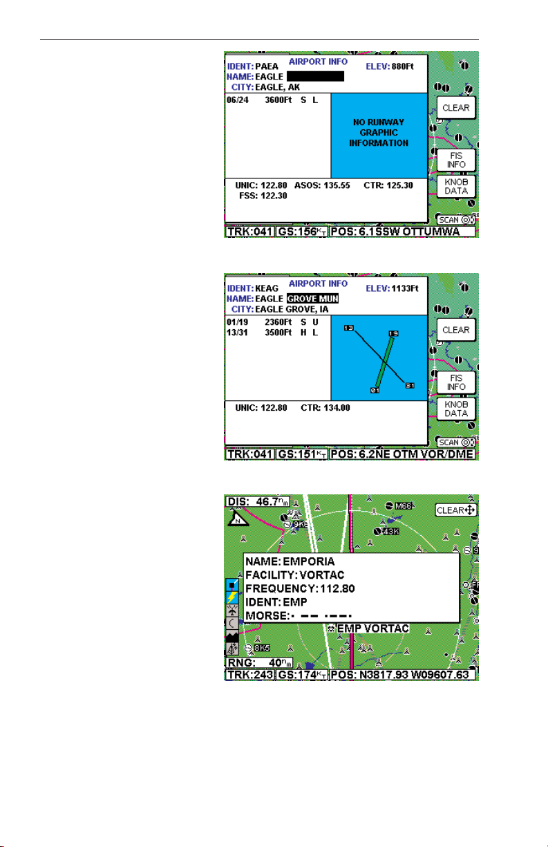
AIRPORT INFORMATION
As shown in Figure 6, you
can display airport information by placing the joystick
pointer over an airport icon
and pressing MORE INFO.
All the information given here
is derived from the built-in
Jeppesen database.
Runway surfaces are shown
as an H for hard and an S for
soft. Lighting is shown as an
L for lit and a U for unlit.
In addition to using the joystick to get airport information, the Control Knob may
also be used. Sometimes it
is not desirable to pan the
map to an airport location
some distance from the present position. In this case
simply turn either knob and
the AIRPORT INFO Page
will appear as in Figure 6.
12
Rev 9 Feb/2009
KMD 550/850 Pilot's Guide
Operation
Figure 6
Figure 7
Page 29

Rev 9 Feb/2009 KMD 550/850 Pilot's Guide
13
Operation
Finding Airports by Entering Identifier
1. The cursor will be over the first character of the airport identifier.
Select the desired character by turning the inner knob.
2. Turn the outer knob one click clockwise to move the cursor to the
next character field as shown in Figure 7. Turn the inner knob to select
the desired character.
3. Continue changing fields and entering characters until the desired airport information is displayed.
4. Press the CLEAR Soft Key to return to the moving map or press the
FIS INFO Soft Key (if FIS is installed) to view the FIS TEXT Page for the
selected airport. Then press the MAP key to return to the moving map.
Finding Airports by Scanning Identifiers
1. The cursor will be over the first character of the airport identifier as
shown in Figure 6. Select the desired character by turning the inner
knob.
2. Turn the outer knob one click clockwise to move the cursor to the
next character field as shown in Figure 7. Turn the inner knob to select
the desired character.
3. Press the KNOB SCAN
Soft Key. Note that the
Control Knob label has
changed to SCAN and the
cursor is on the last two character fields. See Figure 8.
4. Turning the inner knob will
now sequence through all
airport identifiers in the database beginning with KM,
which were the first two characters selected in Figure 8.
The outer knob may be used
to select one or all the fields for scanning. The more characters selected
in the identifier, the shorter the scan list.
5. Press the CLEAR Soft Key to return to the moving map or press the
FIS INFO Soft Key (if FIS is installed) to view the FIS TEXT Page for the
selected airport. Then press the MAP key to return to the moving map.
Figure 8
Page 30

Finding Airports by Name or City
When the identifier of the desired airport is known (or a part thereof), the
methods previously described can be used for selection. However, if the
identifier is not known, the name of the airport can be entered. The
system will also allow entry
of just the first few characters
of the airport name to help
find it in the database. If neither the identifier nor the
location name is known, the
city/state can be scanned.
To Enter Airport Name:
The following example
shows entering EAGLE
GROVE MUN as an airport.
1. If necessary, press the
KNOB DATA Soft Key so
that DATA is displayed as
the Control Knob label.
2. Turn the outer knob clockwise to select the first character in the name field as
shown in Figure 9.
3. Turn the inner knob to
select an E as in Figure 10.
4. Turn the outer knob clockwise until the cursor is positioned for the next character.
Turn the inner knob to select
an A as in Figure 11.
14
Rev 9 Feb/2009
KMD 550/850 Pilot's Guide
Operation
Figure 9
Figure 10
Figure 11
Page 31

Rev 9 Feb/2009 KMD 550/850 Pilot's Guide
15
Operation
5. Turn the outer knob clockwise until the cursor is positioned for the next character.
Turn the inner knob to select
a G as in Figure 12.
6. Since EAGLE is now dis-
played, turn the outer knob
clockwise until the cursor is
positioned for the next character entry as shown in
Figure 13.
7. Turn the inner knob to
select a G as in Figure 14.
The desired airport is now
displayed because it is the
first database instance with a
G in this field.
8. Press the CLEAR Soft
Key to return to the moving
map or press the FIS INFO
Soft Key (if FIS is installed) to
view the FIS TEXT Page for
the selected airport. Then
press the MAP key to return
to the moving map.
To Scan for Airport Name:
The following example shows
scanning for EAGLE GROVE
MUN as an airport.
1. Repeat Step 1 through 5
of the previous procedure.
2. Press the KNOB SCAN
Soft Key. The Control Knob
label will now display SCAN .
Figure 13
Figure 14
Figure 12
Page 32
16
Rev 9 Feb/2009
KMD 550/850 Pilot's Guide
3. Turn the outer knob clockwise until the cursor is positioned as in Figure 15.
4. Turn the inner knob to
sequence through all the airport names in the database
beginning with EAGLE, stopping at the desired name as
in Figure 16.
NOTE: This same method
may be used with the name
of the city where the airport is
located.
5. Press the CLEAR Soft
Key to return to the moving
map or press the FIS INFO
Soft Key (if FIS is installed) to
view the FIS TEXT Page for
the selected airport. Then
press the MAP key to return
to the moving map.
NAVAID INFORMATION
As explained previously, you
can access additional Navaid
information by placing the
joystick pointer over a VOR
or NDB icon and pressing
MORE INFO. Full details of
the Navaid are listed, type,
frequency and ident as
shown in Figure 17. The fifth
line in the box is a visual representation of the Morse
Code identifier.
GENERAL ICON
INFORMATION
As explained previously, you can display additional information about an
icon by placing the joystick pointer over any data icon that is not an airport, VOR or NDB and pressing MORE INFO. All available information
concerning the chosen data item is then listed.
Operation
Figure 16
Figure 17
Figure 15
Page 33
Rev 9 Feb/2009 KMD 550/850 Pilot's Guide
17
Operation
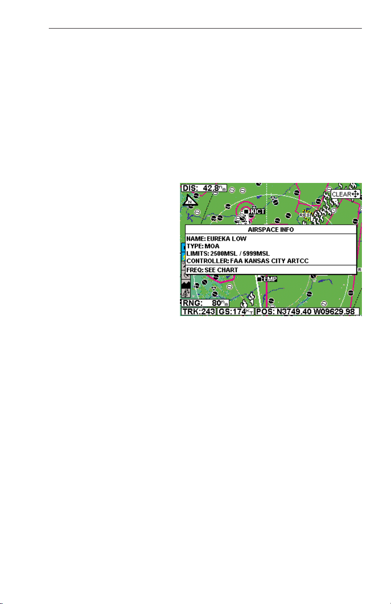
AIRSPACE INTERROGATION
In order to interrogate a piece of airspace on the Map display, move the
joystick operated pointer and point at one of the airspace boundaries.
After releasing the joystick, the software will search the airspace database and after a short time will re-draw the piece of airspace to which
you have pointed in a bolder line with a basic information tag attached.
IMPORTANT:
When a single airspace boundary line is shared by two different
pieces of airspace (which is very common), the airspace with the
lower vertical limit will always be highlighted.
Once it is determined the
piece of airspace highlighted
is the piece for which information is wanted (you may
have to zoom out to verify
this, but beware, some airspace switches off as you
zoom out dependent on the
settings made in Map Setup),
press MORE INFO and additional information will be displayed as in Figure 18.
The information shown on
this display is all the information from the internal Jeppesen database that is relevant to the airspace
selected. If some of the fields are blank or say SEE CHART, this means
that Jeppesen data is not available for that particular item.
DISPLAY FLIGHT PLAN DATA
If the host GPS is outputting data in the Bendix/King equivalent ARNAV
R-30 (RS232) data sentence format, in LEG mode, the active flight plan
will be sent to the KMD 550/850 and can be displayed as an overlay on
the map (see Overlaying Data). An exception to this is during the curved
flight segments of approaches (i.e. DME arcs, procedural turns and
holds) when most GPS units stop outputting flight plan data but continue
to output positional data. During a DME arc or procedural turn, the KMD
550/850 will continue to show position, track and ground speed but the
curved line depicting the arc or turn will not be displayed. In OBS mode,
some GPS units will not be able to provide flight plan data. Present position is still provided and flight plans will be displayed as soon as the
mode is returned to LEG.
Figure 18
Page 34

18
Rev 9 Feb/2009
KMD 550/850 Pilot's Guide
If the KLN 94 is supplying the
GPS data, and the KLN 94 is
configured to produce the
“Enhanced RS-232 GPS
bus”, the KMD 550/850 will
display the curved paths
including DME arcs,
Procedure Turns and Holding
Patterns. Figure 19 is an
example of a DME arc display.
Important Note for Garmin
GPS Users
Although Garmin products output the Bendix/King equivalent ARNAV R30 (RS232) data sentence format, when put into OBS Mode some
Garmin GPS units stop sending all data including GPS position. In these
circumstances your KMD 550/850 will display an error message saying
NO EXTERNAL GPS DATA since it is not receiving present position.
In the case of DME arcs, turns and holds, some Garmin GPS units send
the flight plan information as if there was no arc or curved flight path.
Therefore the KMD 550/850 has no option but to connect the beginning
and end waypoints of the arc or curve with a straight line. Under these
circumstances the line on the KMD 550/850 MUST BE IGNORED.
OVERLAYING DATA
Some data from functions not currently selected on the Function Select
Keys can be displayed on the selected function. By pressing the OVLY
Key a display similar to Figure 20 will be displayed.
The base display will reflect the current function
selected on the Function Select Keys. Available
overlay options will be displayed as Soft Labels.
Pressing the soft key associated with the desired
overlay will toggle between
overlay on and off. Pressing
SAVE & EXIT will return to
the selected function. The
overlay status will remain as
saved until changed again by
pressing the OVLY Key. The
following table shows the
available overlay options
based on the function
presently being displayed.
Note that not all options are
available in all installations.
Operation
Figure 19
Figure 20
Page 35

Rev 9 Feb/2009 KMD 550/850 Pilot's Guide
19
Operation
OVERLAY TYPE
MMOODDEE FFLLIIGGHHTT PPLLAANN SSTTOORRMMSSCCOOPPEE®®TTRRAAFFFFIICC MMEETTAARR DDAATTAA LLIINNKK SSCCIITT TTFFRR
LLIIGGHHTTNNIINNGG
MAP - TOPO ON Yes Yes
1
Yes
2
Yes No No Yes
5
MAP - TOPO OFF Yes Yes
1
Yes
2
Yes No No Yes
5
WX - Weather Radar Yes
1
Yes Yes
3
No No No No
WX - Stormscope
®
Yes
1
N/A No No No No No
WX - NEXRAD Yes Yes
1
Yes No Yes Yes No
WX - Precipitation Type
5
Yes No No No Yes Yes No
WX - Freezing Levels
5
Yes No No No No No No
WX - Winds Aloft
5
Yes No No No No No No
WX - Graphical METAR Yes No No N/A No No No
WX - Graphical AIRMET Yes Yes
1
No No No No No
WX - Graphical SIGMET Yes Yes
1
No No No No No
WX - Graphical Convective Yes Yes
1
No No No No No
SIGMET
WX - Graphical Wx Watches Yes
4
Yes
1, 4
No No No No No
TERR Yes Yes
1
Yes
2
No No No No
TRFC Yes
1
No N/A No No No No
1 Requires remote heading input
2 TCAS/TAS requires remote heading input
3 TIS requires remote heading input
4 Not available with XM
5 Not available with VHF Datalink FIS
Pressing and holding the
OVERLAY key while in one
of the FIS Modes will display
the FIS Overlays windows as
show in the figure below.
This window displays the
status of the overlays of the
current mode that is being
displayed. The window will
no longer be displayed when
the overlay key is released.
Page 36

Operation
20
Rev 9 Feb/2009
KMD 550/850 Pilot's Guide
Pressing and holding the
OVERLAY key while in one
of the Map Modes will display
the Map Overlays windows
as show in the figure below.
This window displays the
status of the overlays of the
current mode that is being
displayed. The window will
no longer be displayed when
the overlay key is released.
DISPLAYING WEATHER RADAR (KMD 850 ONLY),
STORMSCOPE®OR FLIGHT INFORMATION SERVICES
Pressing the WX Function Select Key will sequence
through weather radar, Stormscope®and Datalink
weather. For operation of the weather radar and Datalink
weather, see the separate section pertaining to the
desired function if provided.
DISPLAYING TRAFFIC
Pressing the TRFC Function Select Key to display traffic.
For operation of the Traffic Function, see the separate
section on traffic operation if provided.
SELECTING THE ENHANCED GROUND
PROXIMITY WARNING SYSTEM
Pressing the TERR Function Select Key to display
EGPWS. For operation of the EGPWS, see the separate
section on EGPWS operation if provided.
VIDEO DISPLAY
If the unit has a NTSC video source connected, pressing
AUX will display the video. Note that on the video display no icons are shown.
Page 37
KMD 550/850 Pilot's Guide
21
SYSTEM SETUP
This section of the manual is designed to provide step by step instructions for the setup of the KMD 550/850. Note that not all features discussed in this section are available in all installations.
INTRODUCTION
The KMD 550/850 unit is operated via a joystick, a series of five Power
Keys located along the right side of the unit, a series of Function Select
Keys located along the bottom, and an inner and outer Control Knob.
The joystick allows movement of the pointer in MAP mode and is used to
select and change setup fields. The appropriate key labels for a particular page are configured in software and displayed alongside the appropriate key. The rotary brightness control is used for adjusting the brightness of the display.
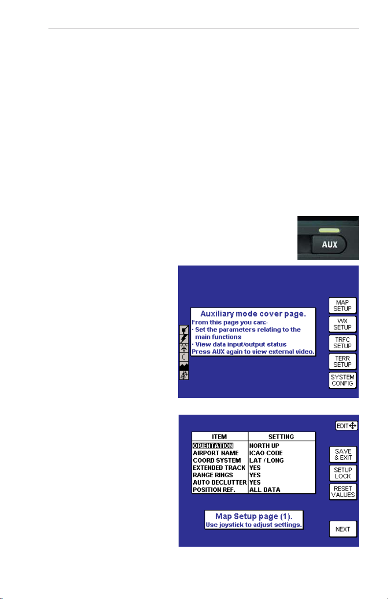
MAP SETUP
Press the AUX Function Key
to display Figure 21. Press
the MAP SETUP Key to dis-
play Figure 22. Use the joystick to select and change
the desired fields.
NOTE: If a configuration
password is requested, map
setup may not be allowed.
ORIENTATION: Set either
in Track Up or North Up.
AIRPORT NAME: Labels
airports in MAP MODE either
with ICAO code, airport or
city names.
COORD SYSTEM: Determines whether the unit operates with reference to
Lat/Long, UTM or OSGB.
Note: OSGB is only defined
for Great Britain.
Rev 9 Feb/2009
System Setup
Figure 21
Figure 22
Page 38

22
KMD 550/850 Pilot's Guide
Rev 9 Feb/2009
EXTENDED TRACK: Turns on or off the extended track line, which is
drawn ahead of the present position in the direction of the present track.
RANGE RINGS: Turns range rings on or off in MAP Mode.
AUTO DECLUTTER: Turns on or off. If a higher priority icon label
(Airport) is found to clash with a lower priority icon label (City) already on
the display, the lower priority icon label will be removed.
POSITION REF: Defines the reference to which the present position is
given in MAP MODE, either to all available data, VORs only or VORs
and Airports only.
Press the NEXT Key to display Figure 23. Use the joystick to select and change
the desired fields.
ICON: Shows the symbol
used to designate the associated item.
TOPO ON/TOPO OFF:
Shows the color associated
with the selected item when
the topographic map is on or
off.
ICON MAX: This field can
be set to the maximum
range, in nautical miles, that
this item’s symbol is displayed on the map display.
NAME MAX: This field can
be set to the maximum
range, in nautical miles, that
the text name of this item is
displayed on the map display.
MIN: This field can be set to
the minimum range, in nautical miles, that this item’s
symbol and text name is displayed on the map display.
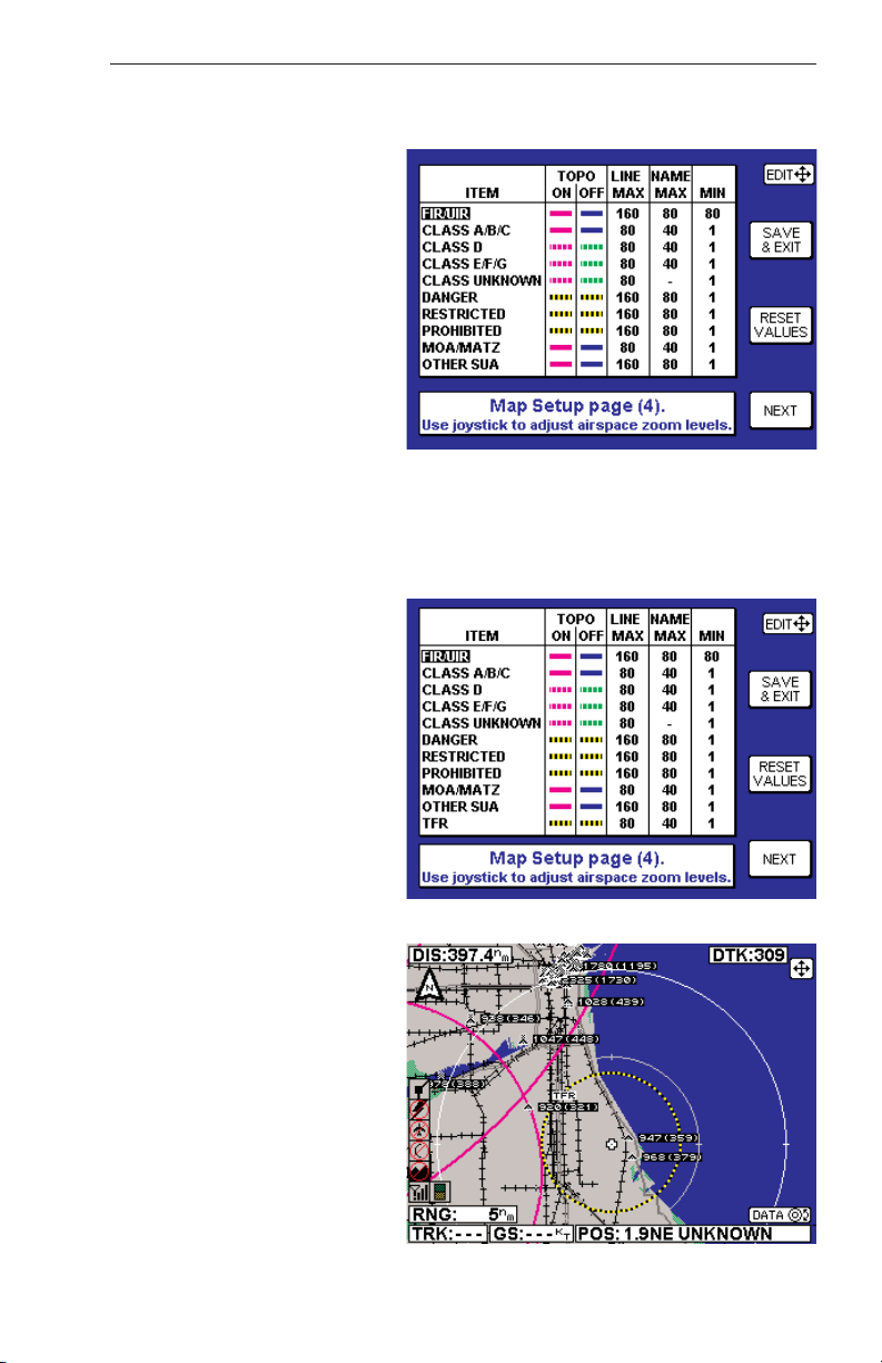
Press the NEXT Key to display Figure 24. Use the joystick to select and
change the desired fields.
LINE: Shows the symbol used to designate the associated item.
TOPO ON/TOPO OFF: Shows the color associated with the selected
item when the topographic map is on or off.
System Setup
Figure 23
Figure 24
Page 39
KMD 550/850 Pilot's Guide
23
Rev 9 Feb/2009
LINE MAX: This field can be set to the maximum range, in nautical
miles, that this item’s symbol is displayed on the map display.
NAME MAX: This field can
be set to the maximum range,
in nautical miles, that the text
name of this item is displayed
on the map display.
MIN: This field can be set to
the minimum range, in nautical miles, that this item’s
symbol and text name is displayed on the map display.
Press NEXT to display Figure
25. Again, use the joystick to
select and change the desired
fields. The previous field descriptions also apply to this display. After
making all desired changes, press the SAVE & EXIT Key to save all
changes and exit the setup function. Figure 21 will again be displayed.
At any time the RESET VALUES key can be pressed to return to the
default setings on that particular display.
Note: Temporary Flight
Restrictions (TFR) will only
be displayed when there is a
valid XM subscription.
TEMPORARY FLIGHT
RESTRICTIONS
Temporary Flight Restrictions,
(TFR), are part of the products
received from the XM weather
service. If there is not an
active XM subscription TFR’s
will not be displayed. They will
only be displayed on the Map
Page of the KMD 550/
850. TFR’s are enabled from
the MAP Setup Page (4) as
shown in Figure 26. Changing
the settings for TFR’s is the
same as changing settings on
the map display.
An example of a TFR is
shown in Figure 27.
System Setup
Figure 25
Figure 26
Figure 27
Page 40

24
KMD 550/850 Pilot's Guide
Use the joystick to cursor
over the boundary of the
TFR. A popup window will
display TFR and the floor
and ceiling of the restricted
area. Figure 28a shows the
display with the topo map off
and Figure 28b shows the
display with the topo map on.
Press the MORE INFO soft
key and another popup
window will display the published detail on the restricted
area. See Figure 29.
Moving the joystick will clear
the popup windows.
Rev 9 Feb/2009
System Setup
Figure 28a
Figure 29
Figure 28b
Page 41

Rev 9 Feb/2009 KMD 550/850 Pilot's Guide
25
System Setup
WX-500 STORMSCOPE
®
SETUP
Press the WX SETUP Key
shown in Figure 21. Figure
30 will now be displayed.
Press the STORM SCOPE
Key to display Figure 31.
Press the NOISE CHECK
Key to display the noise
check display in Figure 32.
Figure 30
Figure 31
Figure 32
Page 42

26
Rev 9 Feb/2009
KMD 550/850 Pilot's Guide
System Setup
Press the PREV PAGE Key
to again display Figure 31.
Press the STRIKE TEST
Key to display the strike test
page shown in Figure 33.
Press the PREV PAGE Key
to again display Figure 31.
To perform a system self
test, press the SELF TEST
Key and the self test page
will be displayed as shown
in Figure 34.
After the Self Test is complete, Figure 35 will be displayed.
Press the PREV PAGE Key
to again display Figure 31.
Press PREV PAGE again to
exit stormscope setup.
Figure 33
Figure 34
Figure 35
Page 43

KMD 550/850 Pilot's Guide
27
Rev 9 Feb/2009
DATA CARDS
DATA AREAS
Honeywell produces three data cards based on the ICAO/ARINC geographic areas for KMD 550/850 that cover the entire world. Each card
for each area contains the operating software, the appropriate Jeppesen
aeronautical data, cartographic data and topological data to a high resolution. Also included is a low resolution map of the rest of the world.
The ten ICAO/ARINC areas along with their three letter identifiers are:
AFR Africa CAN Canada EEU Eastern Europe
EUR Europe LAM Latin America MES Middle East
PAC Pacific SAM South America SPA South Pacific
USA USA
These areas are combined to produce three data cards covering the
entire world that contain the following data:
AMR Americas - comprising CAN, USA, LAM, SAM
ATI Atlantic International - comprising EUR, AFR, EEU, MES
PAI Pacific International - comprising PAC, SPA, EEU, MES
Data Cards
Page 44

28
KMD 550/850 Pilot's Guide
Rev 9 Feb/2009
CHANGING THE DATA CARD
To change the data card follow these simple steps:
1. Turn off the KMD 550/850.
2. Grasp the data card and pull it straight out of its socket.
3. With the card facing upward, as indicated on it’s label, insert the new
data card being careful to align the card with the socket then press the
new card firmly into place.
4. Turn the unit on and check for correct operation. If the new data card
contains a newer version of operating software the unit will update the
operating system to this newer version. Status bars will be displayed
during the update process.
DATABASE INFORMATION
Due to Honeywell’s policy of continual development and routine database updates, new data cards will become available every 28 days. As
a registered owner of a KMD 550/850, you will be offered a 1/3/6/12
monthly data card subscription.
DATABASE CYCLE INFORMATION
Keeping the database current in the KMD 550/850 is the user’s responsibility. Honeywell maintains its databases to be current at all times to the
latest Jeppesen 28-day data cycle.
For data card subscriptions and FIS subscribers, contact Wingman
Services at the following numbers:
1-800-247-0230 if calling within the United States or Canada
(913) 712-3145 if calling from outside the United States or Canada
(913) 712-3904 FAX
e-mail: nav.database@honeywell.com
Visit Wingman Services at www.bendixking.com
For information about software revisions and the most current pilot’s
guide and addendums, visit www.bendixking.com/kmd.
Data Cards
Page 45

Rev 9 Feb/2009 KMD 550/850 Pilot's Guide
29
DEFINITIONS, ACRONYMS AND ABBREVIATIONS
DEFINITIONS
Alphabetic: any of the following characters (b/ is a space): b/ABCDE-
FGHIJKLMNOPQRSTUVWXYZ.
Alphanumeric: any of the following characters (b/ is a space):
b/ABCDEFGHIJKLMNOPQRSTUVWXYZ0123456789.
Baud: bits per sec
Barometric Altitude: pressure altitude corrected for barometric
altimeter setting.
Bearing To User Waypoint: bearing from the present position to the
active user waypoint measured clockwise relative to true or magnetic
north (true is implied unless magnetic is specified).
Cross Track Error: distance from the present position to the nearest
point on the desired course, and the direction (right or left) from the
desired course to the present position.
Cursor Field: a character position or group of adjacent character positions on which a cursor can appear.
Data Field: a character position or group of adjacent character positions
which display a single data item; a data field may be a single character
cursor field, or may contain multiple characters.
Data List: an ordered list of data elements which a given cursor field
can accept.
Desired Track: The angle that the desired flight path makes with
respect to true north at the point nearest the present position. Magnetic
desired track uses the local magnetic variation.
Distance To Waypoint (DIS): distance from the present position to the
active waypoint.
Ground Speed: absolute value of the rate of change of position.
Headwind: difference between true airspeed and ground speed when
true airspeed is more than ground speed.
Knots: Nautical Miles/hr
Special Use Airspace: any of the following: prohibited area, restricted
area, warning area, alert area, MOA, Class CARSA, Class BTCA,
unknown, danger, caution, training, CTA, or TMA type.
Definitions, Acronyms & Abbreviations
Page 46

30
Rev 9 Feb/2009
KMD 550/850 Pilot's Guide
Tailwind: difference between ground speed and true airspeed when
ground speed is more than true airspeed.
Track: angle of the aircraft’s path over the ground measured clockwise
relative to north.
ACRONYMS AND ABBREVIATIONS
AC: Alternating Current
ACT: Active (user waypoint or flight plan)
ADF: Automatic Direction Finder
AGL: Above Ground Level
AMR: Americas data area
ANSI: American National Standards Institute
APR: Approach
APT: Airport
ARTCC: Air Route Traffic Control Center
ASCII: American Standard Code for Information
Interchange
ASOS: Automated Surface Observation System
ATC: Air Traffic Control
ATF: Aerodrome Traffic Frequency
ATI: Atlantic International data area
ATIS: Automatic Terminal Information Service
A/C: Aircraft
baud: or Baud Rate; a measurement of data transmission
speed
BRG: Bearing
CAA: Civil Aviation Authority
CAS: Calibrated Airspeed
com: communication
CDI: Course Deviation Indicator
CTA: Control Area
CTAF: Common Traffic Advisory Frequency
CTR: Control Zone
Definitions, Acronyms & Abbreviations
Page 47

KMD 550/850 Pilot's Guide
31
Rev 9 Feb/2009
CTZ: Control Tower Zone
dB: decibels
DEP: Departure
DC: Direct Current
DIS: Distance
DME: Distance Measuring Equipment
DOT: United States Department of Transportation
DTK: Desired Track
EFIS: Electronic Flight Instrument System
EGPWS: Enhanced Ground Proximity Warning System
ELT: Emergency Locator Transmitter
ESA: Enroute Safe Altitude
ETE: Estimated Time Enroute
FAA: Federal Aviation Administration
FAR: Federal Aviation Regulations
FIR: Flight Information Region
FIS-B: Flight Information Services - Broadcast
FPL: Flight Plan
FPM: Feet Per Minute
FSS: Flight Service Station
ft: feet
FT: Feet
G: Gravitational Acceleration = 32.2 ft/sec2 = 19.3
kt/sec2
GAL: Gallons
GCO: Ground Communications Outlet
GPS: Global Positioning System
GRND: Ground
hr: hour
HSI: Horizontal Situation Indicator
Hz: Hertz
Definitions, Acronyms & Abbreviations
Page 48

32
Rev 9 Feb/2009
KMD 550/850 Pilot's Guide
IEEE: Institute of Electrical and Electronics Engineering
IFR: Instrument Flight Rules
in.: inches
INT: Intersection
kHz: kilohertz
Kt.: Knots
KΩ: Kilohms
LAT: Latitude
LB: Pounds
LED: Light Emitting Diode
LON: Longitude
LONG: Longitude
LRU: Line Replaceable Unit
m: meters
mA: milliamperes
MATZ: Military Air Traffic Zone
mB: millibars
MCOM: Multicom
MHz: Megahertz
mi: statute miles
min: minutes
MOA: Military Operation Area
MSA: Minimum Safe Altitude
MSL: Mean Sea Level
msec: milliseconds
NDB: Non-Directional Beacon
nm: Nautical Miles
NPA: Non Precision Approach
NVM: Non Volatile Memory
OBI: Omni-directional Bearing Indicator
OBS: Omni-directional Bearing Selector
Definitions, Acronyms & Abbreviations
Page 49

Rev 9 Feb/2009
KMD 550/850 Pilot's Guide
33
OSGB: Ordnance Survey of Great Britain
PAI: Pacific International data area
PETE: Pointer ETE
RAD: Radial
REF: Reference
RMI: Radio Magnetic Indicator
RTCA: Radio Technical Commission for Aeronautics
sec: seconds
TAS: True Airspeed
TAT: Total Air Temperature
TD: Time Difference
TFR: Temporary Flight Restrictions
TMA: Terminal Control Area
TOPO: Topographical Data (i.e. coastlines, terrain, rivers,
lakes etc)
TSO: Technical Standard Order
TWR: Tower
UIR: Upper Information Region
UNIC: Unicom
UNS: Unspecified
UTC: Universal Coordinated Time (same as Greenwich
Mean Time)
UTM: Universal Transverse Mercator
V: Volts
VDL: VHF Data Link
VHF: Very High Frequency
VOR: Very High Frequency Omni-directional Radio
Range
VRP: Visual Reference Point
W: Watts
wpt: Waypoint
XM: XM Satellite Weather
Definitions, Acronyms & Abbreviations
Page 50

34
Rev 9 Feb/2009
KMD 550/850 Pilot's Guide
µsec: microsecond
µV: microvolts
°C: degrees Celsius
°F: degrees Fahrenheit
Definitions, Acronyms & Abbreviations
Page 51

KMD 550/850 Pilot's Guide
35
Rev 9 Feb/2009
WX-500 STORMSCOPE®OPERATION
INTRODUCTION
The Bendix/King KMD 550/850 is capable of being interfaced to an L3
WX-500 Stormscope®Series II Weather Mapping Sensor. The WX-500
detects electrical discharges associated with thunderstorms within a 200
nm radius of the aircraft. The information is then sent to the KMD
550/850 and will display the location of the thunderstorms both on the
map displays and on a dedicated Stormscope®display.
For a detailed description of the WX-500 and how to interpret the lightning display and a list of error codes, please reference the WX-500
Stormscope®User’s Guide.
FUNCTIONAL DESCRIPTION
The antenna detects the electric and magnetic fields generated by intracloud, inter-cloud, or cloud-to-ground electrical discharges that occur
within a 200 nm radius of the aircraft and sends the resulting "discharge
signals" to the processor. The processor digitizes, analyzes, and converts the discharge signals into range and bearing data then stores the
data in memory. The WX-500 processor then communicates this information to the KMD 550/850 as 'strikes' and 'cells'. The WX-500 updates
the KMD 550/850 every two seconds.
OPERATION
As mentioned earlier, the WX-500 is controlled through the KMD
550/850. The focus on this section is to provide both background information and a more detailed explanation of the operating procedures.
The following text assumes you have both the WX-500 and the KMD
550/850 switched on and that you have selected the Stormscope®display using the WX Function Select Key on the KMD 550/850.
SELECTING STORMSCOPE®OR WEATHER RADAR
Pressing the WX Function Select Key will toggle between Stormscope
®
and/or Weather Radar, depending on available options.
The weather radar function is only available in the KMD
850. For operation of the weather radar, see the separate section on weather radar operation if provided.
WX-500 Stormscope®Operation
Page 52

36
KMD 550/850 Pilot's Guide
Rev 9 Feb/2009
POWER-UP
At power-up, the WX-500 executes a power-up self test. The self test
takes approximately 25 seconds to ensure that all major WX-500 functions are operating properly. During this period you may receive a NO
DATA RECEIVED FROM STORMSCOPE message, this is normal.
Functions tested include antenna reception, memory and microprocessor
functions. An error message is displayed if a fault is detected.
HEADING STABILIZATION
Some aircraft are equipped with a remote heading reference, such as an
HSI with a slaved directional gyro. This allows the heading stabilization
feature to automatically adjust the position of the discharge points on the
display when the aircraft changes heading. The heading information
comes from a remote heading source installed in the aircraft that has
been connected to the WX-500. If this heading information is valid, the
WX-500 and KMD 550/850 will use it. In the absence of an external
heading reference, such as an aircraft with only a directional gyro, the
KMD 550/850 will not allow stormscope strikes to be overlaid on the Map
display, nor will it allow flight plan data to be overlaid on the stormscope
display.
CLEAR ALL DISCHARGE POINTS
Clearing the discharge points periodically while monitoring thunderstorms is a good way to determine if the storm is building or dissipating.
Discharge points in a building storm will reappear faster and in larger
numbers. Discharge points in a dissipating storm will appear slower and
in smaller numbers. To clear the discharge points, move the joystick on
the KMD 550/850.
Clearing the display is especially important if an external heading reference is not used with the system. The display should be cleared after
changes in heading in order to make the displayed strikes reflect their
true position in relation to the aircraft.
SWITCH BETWEEN WEATHER VIEWS
The KMD 550/850 can display the Stormscope®data
in one of two views, either all round (360°) or forward
looking only (120°). To switch the display press the
VIEW button to toggle between the displays. Figure
36 is an example of the all round view and Figure 37
shows the forward looking view.
WX-500 Stormscope®Operation
Page 53

KMD 550/850 Pilot's Guide
37
Rev 9 Feb/2009
SWITCH BETWEEN DISPLAY MODES
The KMD 550/850 can display the Stormscope®data
in one of two modes, either Cell Mode or Strike Mode.
To switch the display between modes press the
MODE button. The currently selected weather display mode is indicated on the top left of the display
and will toggle between CELL MODE and STRIKE MODE with each
press of the button as shown in Figures 36 and 37. The mode selected
here will remain in effect until you change it, unless the unit is turned off
and back on.
Cell Display Mode
When viewing the dedicated Stormscope®display, if cell display mode is
selected, the KMD 550/850 plots a "+" symbol (discharge point) on the
display when it detects associated discharges within the selected range
and view. The KMD 550/850 will plot another "+" close to the first for
each additional discharge determined to be associated with the group.
The KMD 550/850 will not plot a "+" for any discharge not associated
with a group unless it's detected within a 25 nm radius of the aircraft. The
effect of this clustering algorithm is to display the location of storm cells
instead of individual discharges. The cell display mode is most useful
during periods of heavy electrical discharge activity. Using the cell display mode during these periods frees the pilot from sifting through a display full of discharge points to determine exactly where the storm cells
are located.
If discharges are detected within 25 nm of the aircraft, the normal
stormscope icon in the Functions Legend will change to one such
as that shown here.
WX-500 Stormscope®Operation
Figure 36
Figure 37
Page 54

38
KMD 550/850 Pilot's Guide
Rev 9 Feb/2009
Strike Display Mode
If the strike display mode is selected, the KMD 550/850 immediately
plots an "x" symbol (discharge point) on the display for each individual
discharge it detects within the selected range and view. The strike display mode plots discharge points on the display in relation to where the
discharges are actually detected instead of plotting them close to an
associated group of discharge points as is done in the cell display mode.
The strike display mode is most useful during periods of light electrical
activity because it may plot discharges associated with a building thunderstorm sooner than the cell display mode would.
If discharges are detected within 25 nm of the aircraft, the normal
stormscope icon in the Functions Legend will change to one such
as that shown here.
CHANGING DISPLAY RANGE
To change the displayed range of the Stormscope
®
display, press the RNG ΔΔor RNG ∇∇keys. With each
press of the keys, the display changes to display the
electrical discharge activity detected within the new
range. The range indicator will also change to display
the numerical value of the new range (25, 50, 100, or
200 nm). This new range corresponds to the distance
from the aircraft to the outer range ring on the display.
Your KMD 550/850 stores electrical discharge information for all ranges
simultaneously to provide you with an instant, up-to-date display of electrical discharge activity when you select a new range.
As you move from one range to the next, the 25 nm range is always indicated by the solid inner ring to advise you of your close proximity to thunderstorms. You may also notice that the discharge points are progressively larger on the shorter ranges and smaller on the longer ranges.
This effect makes it easier to spot clusters of discharge points in any
range.
WX-500 Stormscope®Operation
Page 55
KMD 550/850 Pilot's Guide
39
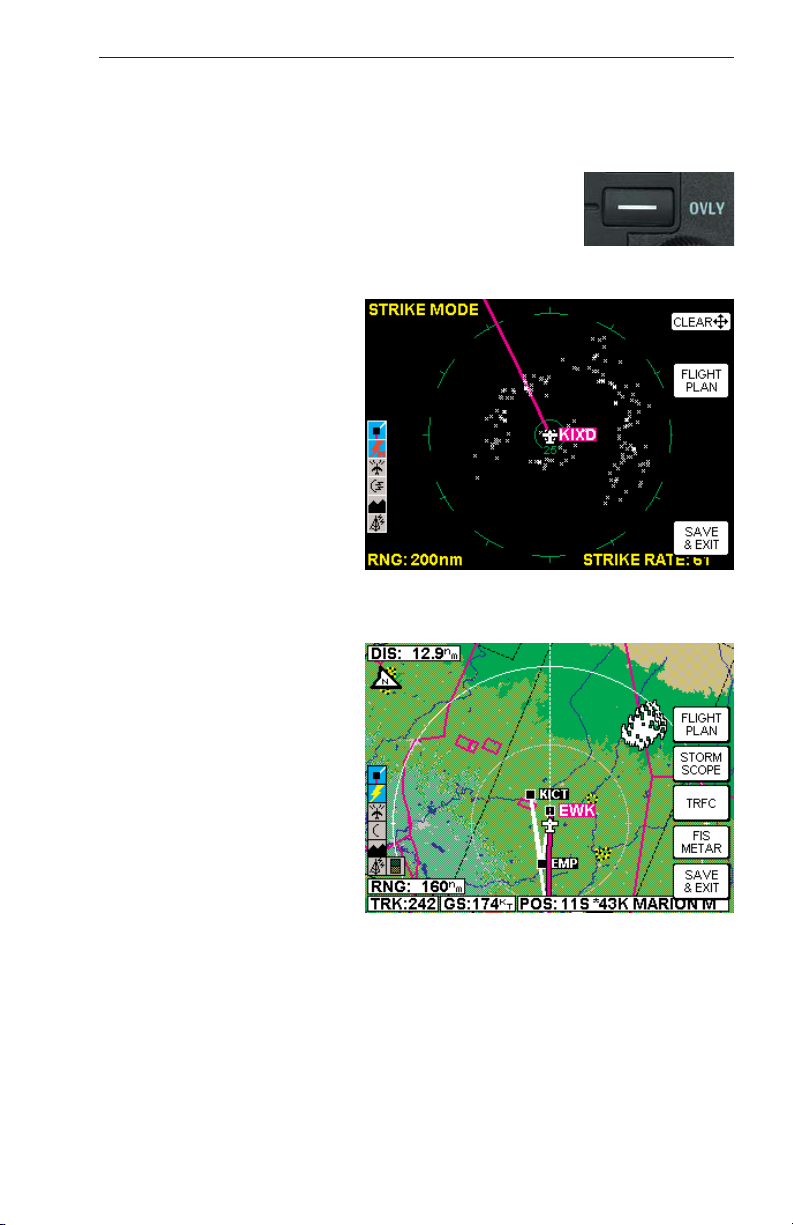
OPERATION IN STORMSCOPE®MODE WITH FLIGHT PLAN
OVERLAY
If the KMD 550/850 is receiving Flight Plan information
from the GPS and a valid heading input is available,
the Flight Plan lines and waypoints may be displayed
on the Stormscope®displays in the form of an overlay.
Press the OVLY key and select FLIGHT PLAN by
pressing the appropriate Softkey as in Figure 38.
NOTE: In order to align the
lightning strikes correctly to
the flight plan lines, heading
information is necessary.
OPERATION IN MAP
DISPLAY
The majority of the text in this
section refers to the dedicated Stormscope®displays
on the KMD 550/850. It is
also possible however to see
thunderstorm cell or strike
data while in the Map display.
Press the OVLY key and
select STORM SCOPE by
pressing the appropriate
Softkey as in Figure 39.
NOTE: Lightning data will
only be displayed on the map
if a heading reference is
available in the form of an
external heading reference
input (described previously).
Any settings made while in
the dedicated Stormscope
®
displays (i.e. cell/strike mode,
clear etc) will be carried over into the Map display. Lightning strikes
must be cleared from the Stormscope®display using the joystick.
The following shows the lightning icons as they appear on the Map display. The range at which lightning icons are displayed is selectable on
Map Setup Page 2.
WX-500 Stormscope®Operation
Rev 9 Feb/2009
Figure 38
Figure 39
Page 56

40
KMD 550/850 Pilot's Guide
WX-500 Stormscope®Operation
Rev 9 Feb/2009
CAUTION
Because the accuracy of the Stormscope
®
sensor is limited, do not
rely on the placement of lightning icons for map range settings less
than 25 nm.
Lightning
Icon
Color Used on Pages Additional Requirements
White MAP (TOPO-ON or
TOPO-OFF)
The small solid icon is used when
the display selected range is 25
nm or greater.
White WX, TRFC, TERR
White
Outline
MAP (TOPO-ON or
TOPO-OFF)
The large outlined icon is used
when the display selected range is
less than 25 nm.
White
Outline
WX, TRFC, TERR
Page 57

KMD 550/850 Pilot's Guide
41
WX-1000E Stormscope®Operation
Rev 9 Feb/2009
WX-1000E STORMSCOPE®OPERATION
INTRODUCTION
The Bendix/King KMD 550/850 is capable of being interfaced to an L3
WX-1000E Stormscope®Series II Weather Mapping Sensor. The WX1000E detects electrical discharges associated with thunderstorms within
a 200 nm radius of the aircraft. The information is then sent to the KMD
550/850 and will display the location of the thunderstorms both on the
map displays and on a dedicated Stormscope®display.
For a detailed description of the WX-1000E and how to interpret the lightning display, please reference the WX-1000E Stormscope®User’s
Guide.
FUNCTIONAL DESCRIPTION
The antenna detects the electric and magnetic fields generated by intracloud, inter-cloud, or cloud-to-ground electrical discharges that occur
within a 200 nm radius of the aircraft and sends the resulting "discharge
signals" to the processor. The processor digitizes, analyzes, and converts the discharge signals into range and bearing data then stores the
data in memory. The WX-1000E processor then communicates this information to the KMD 550/850 as areas of detected lightning (not individual
lightning discharges).
If areas of lightning are detected within 25 nm of the aircraft, the
normal stormscope icon in the Functions Legend will change to
one such as that shown here.
OPERATION
As mentioned earlier, the WX-1000E lightning information is displayed on
the KMD 550/850. The focus on this section is to provide both background information and a more detailed explanation of the operating procedures. The following text assumes you have both the WX-1000E and
the KMD 550/850 switched on and that you have selected the
Stormscope®display using the WX Function Select Key on the KMD
550/850.
Page 58

42
KMD 550/850 Pilot's Guide
Rev 9 Feb/2009
SELECTING STORMSCOPE®OR WEATHER RADAR
Pressing the WX Function Select Key will toggle
between Stormscope®and/or Weather Radar,
depending on available options.
The weather radar function is only available in the KMD
850. For operation of the weather radar, see the separate section on weather radar operation if provided.
POWER-UP
At power-up, the WX-1000E executes a power-up self test. The self test
takes approximately 15 seconds to ensure that all major WX-1000E
functions are operating properly. During this period you may receive a
NO DATA RECEIVED FROM STORMSCOPE message, this is normal.
Functions tested include antenna reception, memory and microprocessor
functions. An error message is displayed if a fault is detected.
SWITCH BETWEEN WEATHER VIEWS
The KMD 550/850 can display the Stormscope®data
in one of two views, either all round (360°) or forward
looking only (120°). To switch the display press the
VIEW button to toggle between the displays. Figure
40 is an example of the all round view and Figure 41
shows the forward looking view.
CHANGING DISPLAY RANGE
To change the displayed range of the Stormscope
®
display, press the RNG ΔΔor RNG ∇∇keys. With each
press of the keys, the display changes to display the
WX-1000E Stormscope®Operation
Figure 40
Figure 41
Page 59
KMD 550/850 Pilot's Guide
43
Rev 9 Feb/2009
lightning activity detected within the new range. The range indicator will
also change to display the numerical value of the new range (25, 50,
100, or 200 nm). This new range corresponds to the distance from the
aircraft to the outer range ring on the display.
As you move from one range to the next, the 25 nm range is always indicated by the solid inner ring to advise you of your close proximity to thunderstorms.
OPERATION IN STORMSCOPE®MODE WITH FLIGHT PLAN
OVERLAY
If the KMD 550/850 is receiving Flight Plan information
from the GPS and the heading input is valid, the Flight
Plan lines and waypoints may be displayed on the
Stormscope®displays in the form of an overlay. Press
the OVLY key and select FLIGHT PLAN by pressing
the appropriate Softkey as in Figure 42.
OPERATION IN MAP
DISPLAY
The majority of the text in this
section refers to the dedicated Stormscope®displays
on the KMD 550/850. It is
also possible however to see
thunderstorm discharge data
while in the Map display.
Press the OVLY key and
select STORM SCOPE by
pressing the appropriate
Softkey as in Figure 43.
WX-1000E Stormscope®Operation
Figure 42
Figure 43
Page 60

44
KMD 550/850 Pilot's Guide
Rev 9 Feb/2009
The following shows the lightning icons as they appear on the Map display. The range at which lightning icons are displayed is selectable on
Map Setup Page 2.
CAUTION
Because the accuracy of the Stormscope
®
sensor is limited, do not
rely on the placement of lightning icons for map range settings less
than 25 nm.
WX-1000E Stormscope®Operation
Lightning
Icon
Intensity
Level
Color Used on
Pages
Comments
1 (Light) White
with
black
border
MAP,
WX,
TERR
The small solid icon is used when the
display selected range is 25 nm or
greater.
The WX-1000E indicates areas of
lightning detected (not individual discharges). Light activity (level 1) is an
area with up to 8 strikes/minute; moderate (level 2) is an area with 9-25
strikes/minute and heavy (level 3) is
an area with 26 or more
strikes/minute.
2 (Moderate)
3 (Heavy)
1 (Light) White
with
black
border
MAP,
WX,
TERR
The large outlined icon is used when
the display selected range is less than
25 nm.
The larger icon reminds the user that
the accuracy of lightning placement is
not as good as that suggested by the
map scale.
2 (Moderate)
3 (Heavy)
Page 61

KMD 550/850 Appendix A
Rev 9 Feb/2009
A-1
APPENDIX A
DISPLAY ICONS
The following is a list of possible map icons on the TOPO ON Map and
TOPO OFF Map.
Feature Conditions Icon / Colors Other Characteristics
TOPO on TOPO off
Political
Boundary
Lines
Dashed
black
line
Not displayed When the 500 nm range
is selected, the name of
the political region will be
displayed with a white on
black label.
Railway
Lines
Dark gray
line with
hack marks
Not displayed May be enabled or dis-
abled based on Map
Setup page (3) setting.
Roads Major Dark
gray
double line with
white on black
iconic label
Not displayed May be enabled or dis-
abled based on Map
Setup page (3) setting.
Prime Dark
gray line
with black on
white iconic
label
Not displayed May be enabled or dis-
abled based on Map
Setup page (3) setting.
Other Dark
gray
thin line with
black on white
iconic label
Not displayed May be enabled or dis-
abled based on Map
Setup page (3) setting.
Victor
Airways
Thick
dashed
cyan line
with black on
white label
Thick
dashed
cyan line with
black on white
label
May be enabled or disabled based on Map
Setup page (3) setting.
Highlighted when the line
is designated with the
joystick pointer. The
airway will be labeled
with the airway identifier.
Heliroutes
Dashed blue
line with black
on white label
Dashed blue
line with black
on white label
May be enabled or disabled based on Map
Setup page (3) setting.
Highlighted when the line
is designated with the
joystick pointer. The
heliroute will be labeled
with the heliroute name.
Page 62

A-2
Rev 9 Feb/2009
KMD 550/850 Appendix A
Feature Conditions
Icon / Colors
Other Characteristics
TOPO on TOPO off
Airspace
Boundary
FIR/UIR Solid
magenta
line with black on
white label
Solid
blue
line with black
on white label
May be enabled or disabled based on Map Setup
page (4) setting.
Highlighted when the line
is designated with the joystick pointer. The boundary
label will be “FIR”, “UIR” or
“F/U” as appropriate for the
airspace type.
Temporary
Flight
Restrictions
Yellow and
black
dashed line with
black on white
label
Yellow
and
black dashed
line with black
on white label
Boundary Label will be
TFR.
Class A/B/C Solid
magenta
line with black on
white label
Solid
blue
line with black
on white label
May be enabled or disabled based on Map Setup
page (4) setting.
Highlighted when the line
is designated with the joystick pointer. The boundary
label will be “A”, “B” or “C”
as appropriate for the airspace type.
Class
D/E/F/G
Dashed
magenta
line with black on
white label
Green
dashed
line with black
on white label
May be enabled or disabled based on Map Setup
page (4) setting.
Highlighted when the line
is designated with the joystick pointer. The boundary
label will be “D”, “E”, “F” or
“G” as appropriate for the
airspace type.
Class
Unknown
Dashed
magenta
line (no
label)
Green
dashed
line (no
label)
May be enabled or disabled based on Map Setup
page (4) setting.
Highlighted when the line
is designated with the joystick pointer.
Danger Yellow
and black
dashed
line with black on
white label
Yellow
and
black
dashed line
with black on
white label
May be enabled or disabled based on Map Setup
page (4) setting.
Highlighted when the line
is designated with the joystick pointer. The boundary
label will be “DGR”.
Restricted Yellow
and black
dashed
line with black on
white label
Yellow and
black dashed
line with black
on white label
May be enabled or disabled based on Map Setup
page (4) setting.
Highlighted when the line
is designated with the joystick pointer. The boundary
label will be “RES”.
Page 63

KMD 550/850 Appendix A
Rev 9 Feb/2009
A-3
Feature Conditions Icon / Colors Other Characteristics
TOPO on TOPO off
Airspace
Boundary
Prohibited Yellow
and
black
dashed line with
black on white
label
Yellow
and
black
dashed line
with black on
white label
May be enabled or disabled based on Map
Setup page (4) setting.
Highlighted when the
line is designated with
the joystick pointer. The
boundary label will be
“PHB”.
MOA/MATZ Solid
magenta
line with
black on white
label
Solid
blue line
with
black on white
label
May be enabled or disabled based on Map
Setup page (4) setting.
Highlighted when the
line is designated with
the joystick pointer. The
boundary label will be
“MOA” or “MATZ” as
appropriate for the airspace type.
Other SUA
(Radar
Area, Alert,
Caution,
Training,
Warning or
Unspecified/
Unknown)
Solid
magenta
line with
black on white
label
Solid
blue line
with
black on white
label
May be enabled or disabled based on Map
Setup page (4) setting.
Highlighted when the
line is designated with
the joystick pointer. The
boundary label will be
“ALT”, “CTN”, “DGR”,
“MOA”, “PHB”, “RES”,
“TNG”, “WNG”, “ADV”,
“CBA”, “TRA”, “TSA”, or
“UNK” as appropriate for
the airspace type.
Cities Black icon
with white
on black label
Not displayed May be enabled or dis-
abled based on Map
Setup page (2) setting.
The label will indicate
the city name.
Highlighted when the
icon is designated with
the joystick pointer.
Intersections
(INTs)
Black icon
with white
on black label
White icon
with white
on black label
May be enabled or disabled based on Map
Setup page (2) setting.
The label will indicate
the intersection identifier. Highlighted when
the icon is designated
with the joystick pointer.
Page 64
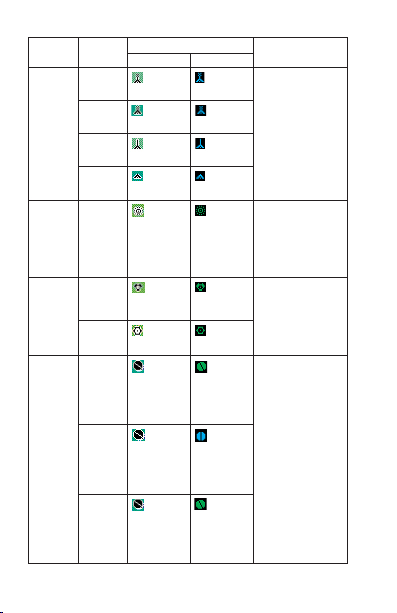
A-4
Rev 9 Feb/2009
KMD 550/850 Appendix A
Feature Conditions Icon / Colors Other Characteristics
TOPO on TOPO off
Obstacles Lighted -
Tall
Black icon
with white
on black label
Cyan icon
with white
on black label
May be enabled or disabled based on Map
Setup page (2) setting.
The label will indicate
the MSL elevation followed by the AGL elevation in parentheses (e.g.
“1546 (590)”).
Highlighted when the
icon is designated with
the joystick pointer.
Lighted Short
Black icon
with white
on black label
Cyan icon
with white
on black label
Unlighted Tall
Black icon
with white
on black label
Cyan icon
with white
on black label
Unlighted Short
Black icon
with white
on black label
Cyan icon
with white
on black label
NDBs Black icon
with white
on black label
Green icon
with white
on black label
May be enabled or disabled based on Map
Setup page (2) setting.
The label will indicate
the NDB’s identifier.
Highlighted when the
icon is designated with
the joystick pointer.
VORs With DME Black icon
with white
on black label
Green icon
with white
on black label
May be enabled or disabled based on Map
Setup page (2) setting.
The label will indicate
the VOR’s identifier.
Highlighted when the
icon is designated with
the joystick pointer.
Without
DME
Black icon
with white
on black label
Green icon
with white
on black label
Airports Has hard
runway +
IFR
approach
Solid black
circle with
line representing primary
runway and
white on black
label
Solid green
circle with
black line representing primary
runway and
white on black
label
May be enabled or disabled based on Map
Setup page (2) setting.
When enabled, the airport label will identify the
ICAO code, city name or
airport name based on
the Map Setup page (1)
setting. Highlighted
when the icon is designated with the joystick
pointer. If the database
does not have runways
for the airport, then the
icon will not indicate a
runway (no line will be
shown).
Has hard
runway, no
IFR
approach
Solid black
circle with
line representing primary
runway and
white on black
label
Solid cyan
circle with
black line representing primary
runway and
white on black
label
IFR
approach
available
Solid black
circle with
line representing primary
runway and
white on black
label
Solid green
circle with
black line representing primary
runway and
white on black
label
Page 65

Feature Conditions Icon / Colors Other
Characteristics
TOPO on TOPO off
Airports Soft or
unknown
runways
Outline
black circle
with line representing primary
runway and
white on black
label
Outline cyan
circle with
cyan line representing primary
runway and white
on black label
May be enabled or
disabled based on
Map Setup page (2)
setting. When
enabled, the airport
label will identify the
ICAO code, city name
or airport name based
on the Map Setup
page (1) setting.
Highlighted when the
icon is designated with
the joystick pointer. If
the database does not
have runways for the
airport, then the icon
will not indicate a
runway (no line will be
shown).
Airport
Runways
Primary,
hard surface
Thick
black line
with white
on black label at
each end
Thick
white line
with white
on black label at
each end
Runways will be
depicted for airports
within 5 nm of the current position when the
selected range is 10
nm or less and the display of airport icons is
enabled on Map Setup
page (2). Runway
ends will be labeled
with the proper runway
identifier if the
selected range is 1
nm. For selected
ranges 2.5 nm through
10 nm, the runways
will not be labeled.
Other hard
surface
Thin
black line
with
white on black
label at each end
Thin white
line with
white on
black label at
each end
Primary,
soft surface
Thick
green line
outlined in
black with white
on black label at
each end
Thick green
line outlined
in white
with white on
black label at
each end
Other soft
surface
Thin
green line
outlined
in black with
white on black
label at each end
Thin green
line out-
lined in
white with white
on black label at
each end
Helipads Black on
white icon
with white on
black label
White on
black icon
with white on
black label
May be enabled or
disabled based on
Map Setup page (2)
setting. The label will
indicate the city name.
Highlighted when the
icon is designated with
the joystick pointer.
Rev 9 Feb/2009
A-5
KMD 550/850 Appendix A
Page 66

A-6
Rev 9 Feb/2009
KMD 550/850 Appendix A
The following shows the various icons that may be seen in the functions
legend, which is displayed in the lower left of the display. Remember,
not all installations will have all available functions.
Feature Conditions Icon / Colors Other
Characteristics
TOPO on TOPO off
Visual
Reference
Points
Black on
white with
white on
black label
Not displayed Will be enabled or dis-
abled based on Map
Setup page (2) setting.
The label will indicate
the VRP name.
Highlighted when the
icon is designated with
the joystick pointer.
Icon Colors Description
Black symbol with a
magenta line below
and a white line above
on a cyan background
Flight plan information being received and displayed.
Black on gray Flight plan information being received but not displayed.
Yellow on cyan
Stormscope®information being received and displayed.
Red on cyan
Stormscope®information being received and displayed.
Strikes have occurred within the last 3 minutes within 25
nm.
Black on gray
Stormscope®information being received but not displayed.
Red on gray
Stormscope®information being received but not displayed. Strikes have occurred within the last 3 minutes
within 25 nm.
Black on gray with red
slash
Stormscope®information not being received; data is
invalid.
Black on cyan Weather radar in standby mode and being displayed.
Note that since the OVLY key is never enabled on the
WX page when the radar is in standby mode, “Hold to
Help” text is not available.
Black on cyan Active weather radar being displayed.
Black on gray Weather radar in standby mode, not being displayed.
Black on gray Weather radar in active mode, not being displayed.
Black on gray with red
slash
Weather radar data invalid / not being received.
Previously in standby.
Black on gray with red
slash
Weather radar data invalid / not being received.
Previously active.
Page 67
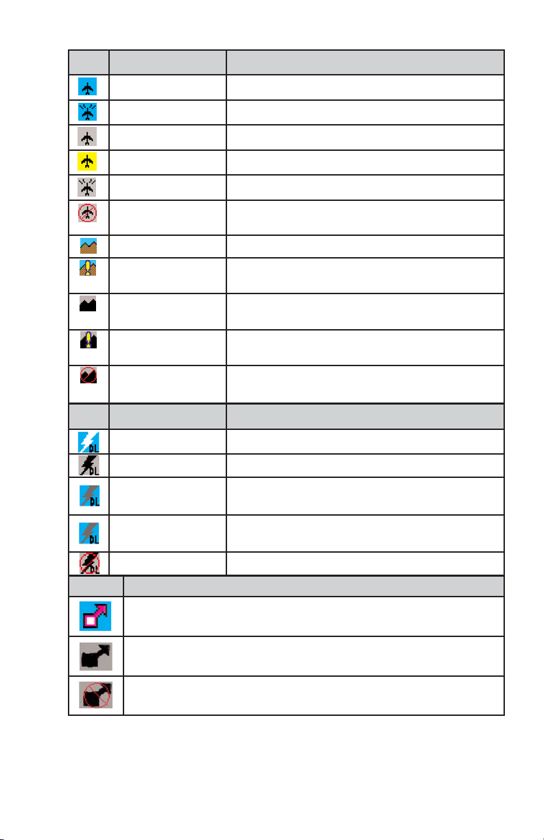
Rev 9 Feb/2009
A-7
KMD 550/850 Appendix A
Icon Colors Description
Black on cyan Traffic sensor in standby mode being displayed.
Black on cyan Active traffic information being displayed.
Black on gray Traffic sensor in standby mode, not being displayed.
Black on yellow TIS service not available.
Black on gray Traffic sensor active, not being displayed.
Black on gray with red
slash
Traffic sensor data invalid / not being displayed.
Brown on cyan EGPWS with warnings are enabled, being displayed.
Brown on cyan with
yellow “!”
EGPWS with warnings are disabled, being displayed.
Black on gray EGPWS with warnings are enabled, not being
displayed.
Black on gray with
yellow “!”
EGPWS with warnings are disabled, not being
displayed.
Black on gray with red
slash
EGPWS data invalid / not being received.
Icon Description
0 min – 15 min Datalink lightning information received and displayed.
0 min – 15 min Datalink lightning information received but not displayed.
15 min – 30 min Datalink lightning information received and displayed but
data is more than 15 minutes old.
15 min – 30 min Datalink lightning information received but not displayed
and data is more than 15 minutes old.
> 30 min Datalink lightning is not being received.
Icon Description
Severe Weather Storm track information being received and displayed.
Severe Weather Storm track information being received but not displayed.
Severe Weather Storm track information not being received / data invalid.
Page 68

A-8
Rev 9 Feb/2009
KMD 550/850 Appendix A
Black on gray. Graphical METAR overlay is available but
not displayed.
Black, green and
yellow on cyan.
Graphical METAR overlay is enabled and
displayed.
Black on gray. Weather data not being received.
Graphical METAR overlay is available but
not displayed.
Black, green and
yellow on cyan.
Weather data not being received.
Graphical METAR overlay is enabled and
displayed.
Black on gray with
red slash.
Radio Fault. Graphical METAR overlay is
available but not displayed.
Black on gray with
red slash; Black,
green and yellow on
cyan.
Radio Fault. Graphical METAR overlay is
enabled and displayed.
TFR data is not being received.
Black on gray. TFR data is being received but is not
currently being displayed.
Black on cyan. TFR data is being received and displayed.
N/A No TFR Icon
present.
N/A
N/A
VDL Icon XM Icon Colors Description
Black on a cyan
background.
No weather data is currently being
received but previously received data is
being displayed on the present page.
Black on a cyan
background.
Weather data is currently being received
from a signal and displayed on the present
page. XM signal is weak.
Black on a cyan
background.
Weather data is currently being received
from a signal and displayed on the present
page. XM signal is marginal.
Black on a cyan
background.
Weather data is currently being received
from a signal and displayed on the present
page. XM signal is good.
Black on gray. Weather data not being received nor
displayed on the present page.
Black on gray. Weather data is currently being received
from a signal but not displayed on the
present page.
Black on gray with
red slash.
Fault with connection or data link radio.
Page 69

n
Honeywell Aerospace
Business and General Aviation
Honeywell International Inc.
One Technology Center
23500 West 105th Street
Olathe, KS 66061
Telephone: (913) 712-0400
FAX: (913) 712-1302
www.honeywell.com
006-18222-0000
Rev. 9 02/09
© 2000-2005, 2007, 2009 Honeywell International Inc.
 Loading...