

Page 1
Quick Reference
KLX 135A
B
GPS/COMM
These simplified operating instructions are only to familiarize you with the
KLX 135A. For detailed operating instructions, please refer to the
KLX 135A Pilot's Guide P/N 006-08789-0000.
CRSR
Pull
SCAN
KLX 135
GPS
B
VOL
OFF
COMM
Pull
25K
Pull
TEST
118®00 ∂∆ KOSH
136.97 > ««««∫∏π««««
>Leg 89.6nm 105kt
NAV 1 >345°To 0:51
APT VOR NDB SUP ACT NAV FPL CAL SET OTH
D
ENTCLRMSG
GPS
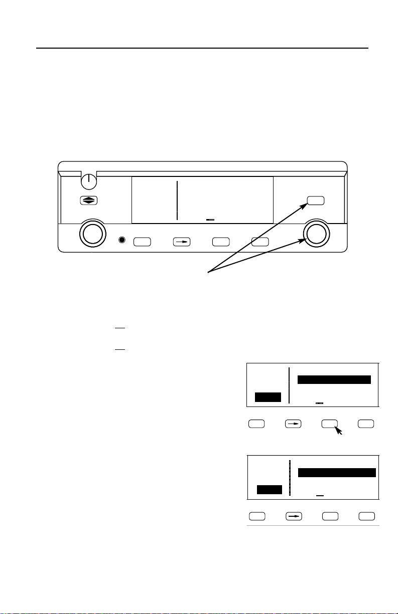
The two concentric knobs and
functions of the KLX 135A. The right inner knob can be pulled out, but for now it
should be pushed in.
When the cursor is off
, the right outer knob changes the page type (APT to VOR to
NDB, etc.) and the right inner knob changes the page number (APT 1 to APT 2).
When the cursor is on
, the right outer knob moves the cursor and the right inner knob
changes the data under the cursor.
To change a cyclic field:
1. Turn on the cursor (by pressing the
ton) and place it over a cyclic field, which is
always preceded by a carat (>).
2. Press the
button to change the cyclic
E
field. One example is the NAV 1 page, which
can display a D-bar (Figure 1) or numerical
course deviation (Figure 2).
To display the Nearest Airport:
1. Press
C
then press
F
button on the right are used to control the GPS
B
B
but-
118®00 ∂∆ KOSH
136.97 >
>Leg 89.6nm 105kt
NAV 1 >345°To 0:51
CRSR
APT VOR NDB SUP ACT NAV FPL CAL SET OTH
««««∫∏π««««
D
Figure 1
118.00 ∂∆ KOSH
136.97 >Fly L 1.1nm
>Leg 89.4nm 105kt
CRSR >345°To 0:51
APT VOR NDB SUP ACT NAV FPL CAL SET OTH
D
.
twice
Figure 2
ENTCLRMSG
ENTCLRMSG
2. The waypoint page for the nearest airport will now be displayed on the screen.
The right inner knob (in the “pulled out” position), may be used in the normal
manner to scan the other nearest airports. With the right inner knob in the “in”
position, you may view all four airport pages for a specific airport.
-1-
Page 2

D To go Direct To a waypoint:
1. Press the
field.
2. Enter desired waypoint using right concentric knobs.
3. Press
ates the Direct To—your D-bar will be centered, and you’re on your way!
4. Alternatively, display desired waypoint on APT, VOR, NDB or SUP page, or move
the cursor over desired waypoint in the active flight plan, then press
press F to confirm.
To create a Flight Plan:
1. Select the active Flight Plan (FPL 0) or one of the stored Flight Plans (FPL 1
through FPL 9) on the screen.
2. Delete existing waypoints from the Flight Plan as necessary by placing the cursor
(
B) over the identifier, pressing E, and then pressing F.
3. If you wish to insert a waypoint identifier between two other waypoints, place the
cursor (
4. With the cursor on, enter the desired waypoint identifier and press
5. The waypoint page for the selected identifier will be displayed. If this is the way-
point you intended to enter, press
D button. The Direct To (DIR) page will be displayed with a waypoint
F to view waypoint information. Press F again to confirm. This initi-
D, then
B) over the waypoint you wish for the new waypoint to precede.
F.
F again.
6. Repeat the waypoint entry process as needed for your Flight Plan.
To calculate the winds aloft:
1. Use the CAL 3 page to calculate the present pressure altitude.
2. Use the CAL 5 page to calculate the present true airspeed (TAS).
3. Turn to the CAL 6 page and enter the present aircraft heading. The headwind or
tailwind component of the wind, and the wind vector (direction and speed) will be
displayed on the last two lines of the CAL 6 page.
-2-
Page 3

NAV 5 (Moving Map) Page Tips
To change the map scale factor:
1. Press the
lower left corner of the map display.
2. Use the right inner knob to change between scale factors.
3. For terminal area operations select AUTO scale factor.
To change what information is displayed on the map:
1. Press the
up a pop-up menu.(Figure 3)
B button. The cursor comes up over the map scale in the
B button, select Menu? and press the F button to bring
118.00
136.97
{>Leg
17.6nm
SUA:off
VOR:off
APT:off
112°
APT VOR NDB SUP ACT NAV FPL CAL SET OTH
Figure 3
• Line 1: Display 5 nearest special use airspaces (SUAs), on or off
• Line 2: Display 9 nearest VORs; on or off
• Line 3: Display 9 nearest airports; on or off
KJAX
OMN
GJ
%
"
%
ORL
%
%
KORL
>117kt
• Line 4: Map orientation; N↑=North up, DTK↑=Desired track up, TK↑ =
Actual track up (when groundspeed > 2 kts)
2. Use the right outer knob to select the desired item, and the right inner
knob to change the setting.
To change the navigation info displayed in the lower right corner:
1. Press the
2. Use the right outer knob to move the cursor to the cyclic field in the lower
right corner.
3. Press E to change between the choices, which are:
• Groundspeed,
• Estimated Time En route (ETE) to the active waypoint (figure 6),
• Crosstrack correction, or
• Magnetic Desired Track (DTK).
B button.
-3-
Page 4

COMM
D
S
D
The two concentric knobs and A (transfer)
button on the left are used to control the COMM
functions of the KLX 135A.
A small “R” appears over the decimal point of the
active frequency when the squelch is broken and
the radio is receiving (Figure4). When the transmitter is keyed a small “T” appears in this same spot.
To tune a COMM frequency:
B
VOL
OFF
COMM
Pull
25K
Pull
TEST
Figure 4
118®40
123.12
>Leg
NAV 1
APT VOR NDB
MSG
1. Use the left outer knob to select the desired number of megahertz
between 118 and 136.
2. Make sure the left inner knob is pushed in, and use it to complete the
desired frequency. In this case, the left inner knob changes the frequency
in increments of 0.05 MHz (50 kHz).
To tune a 25 kHz frequency:
1. Pull the left inner knob out.
2. Use the left knobs to tune the frequency. Notice that the KLX 135A only
displays two digits after the decimal point, so the last digit is implied. For
example, if the frequency is 123.125 MHz, the KLX 135A displays 123.12.
3. When you’re ready to go back to 50 kHz tuning, push the left inner knob
back in. This will allow you to select frequencies with fewer turns of the
knob.
To use the standby frequency entry (flip-flop) mode:
Note: This is the default frequency entry mode.
1. Use the left knobs to tune the standby COMM frequency.
2. To exchange (flip-flop) the active and standby frequencies,
press the A button.
To use the active frequency entry mode:
1. Press and hold the
button for approxi-
A
mately 2 seconds. The standby frequency
will disappear and the active frequency will
be the same as before you pressed the
button (Figure 5).
A
B
VOL
OFF
COMM
Pull
25K
TEST
Pull
2. You can now use the left knobs to tune the
active COMM frequency.
3. To change back to standby frequency entry mode, press the
momentarily.
-4-
118.40
>Leg
NAV 1
APT VOR NDB
MSG
Figure 5
A
button
Page 5

How to QuickTune™ a COMM frequency from the data base:
1. Locate the page for the facility you desire to communicate with (APT,
FSS or CTR). The APT 4 page displays the frequency type (TWR =
Tower Freq, GRND = Ground Control, etc.) and frequency (Figure 6).
B
Pull
VOL
OFF
COMM
TEST
Pull
25K
136.97 KDAL
118.00 ATIS 120.15
>Leg CLR 127.90
APT+4 GRND 121.75
APT VOR NDB SUP ACT NAV FPL CAL SET OTH
D
ENTCLRMSG
CRSR
Pull
SCAN
Figure 6
2. Press the
button to turn the cursor on and use the right outer knob
B
to scan through all the airport’s frequencies (Figure 7). There may be
more frequencies than can be displayed at one time.
B
Pull
VOL
OFF
COMM
TEST
Pull
25K
136.97 KDAL
118.00 ATIS 120.15
ÉÑ>Leg CLR 127.90
APT+4 GRND 121.75
APT VOR NDB SUP ACT NAV FPL CAL SET OTH
D
ENTCLRMSG
CRSR
Pull
SCAN
Figure 7
3. When you have the cursor over the desired frequency, press
and that frequency will become the standby frequency in the COMM
transceiver (Figure 8).
B
Pull
VOL
OFF
COMM
TEST
Pull
25K
136.97 KDAL
120.15 ATIS 120.15
>Leg CLR 127.90
APT+4 GRND 121.75
APT VOR NDB SUP ACT NAV FPL CAL SET OTH
D
ENTCLRMSG
CRSR
Pull
SCAN
KLX 135
GPS
KLX 135
GPS
F
KLX 135
GPS
Figure 8
To adjust the volume by overriding the automatic squelch:
1. Pull out on the small knob in the upper left corner of the KLX 135A (Figure 9). This will either
allow you to receive a distant, weak signal or
give you a noise reference by which to adjust
the volume.
B
VOL
OFF
Figure 9
2. Push the volume knob back in for normal squelch operation.
-5-
Pull
TEST
Page 6

Finding your way around:
There are ten types of pages that may be displayed on the right side of the screen.
Each has multiple page numbers:
Airport (APT) Pages
1 Airport identifier, elevation, name, city,
state/province/country, use type (if
military or private-use)
2 Latitude/longitude, bearing/radial and
distance relative to present position
3 Runway numbers, length, surface, lighting
4 Airport communication frequencies
5 Airport remarks
VOR Pages
1 VOR identifier, frequency, name,
latitude/longitude
2 Magnetic station declination, bearing/
radial, distance relative to present position
NDB Pages
1 NDB identifier, frequency, name,
latitude/longitude
2 Bearing/radial and distance relative to pre-
sent position
Supplemental (SUP) Pages
0 Used to choose method of user-defined
waypoint creation
1 Latitude/Longitude, bearing/radial and
distance relative to present position
2 Reference waypoint (default is nearby
VOR), radial and distance from reference
3 User-defined waypoint remarks
Active Waypoint (ACT) Pages
Waypoint pages for the active waypoint
and the waypoints in FPL 0
Navigation (NAV) Pages
1 Active waypoint/leg, CDI/crosstrack
distance, ground speed,
bearing, time to active waypoint
2 Present position (latitude/longitude or radi-
al/distance)
3 Present time, departure time, ETA at
destination, elapsed flight time
4 Desired track, actual track, bearing to
active waypoint
5 Moving map
Flight Plan (FPL) Pages
0 Active flight plan
1-9 Stored (numbered) flight plans
Calculator (CAL) Pages
1 Trip calculations for distance, bearing, and
ETE
2 Trip calculations for fuel requirements
3 Pressure altitude
4 Density altitude
5 True airspeed (TAS)
6 Winds aloft
Setup (SET) Pages
1 Position initialization for GPS receiver
2 Date, time, and time zone initialization
3 Data base update
4 Turn anticipation enable/disable
5 Default first waypoint character
6 Nearest airport criteria
7 SUA alert enable/disable
8 Baro set, indicated altitude, baro set units
Other (OTH) Pages
1 GPS receiver state, estimated position
error
2 GPS satellite signal status
3 List of user-defined waypoints
4 List of airports and user-defined
waypoints with stored remarks
5 Software versions
AlliedSignal Inc.
Electronic & Avionics Systems
One Technology Center
23500 West 105th Street
Olathe, KS 66061
Telephone (913) 782-0400
©1995, 1996 AlliedSignal Inc.
7/96 006-08790-0000 Printed in USA
A
 Loading...