

Page 1
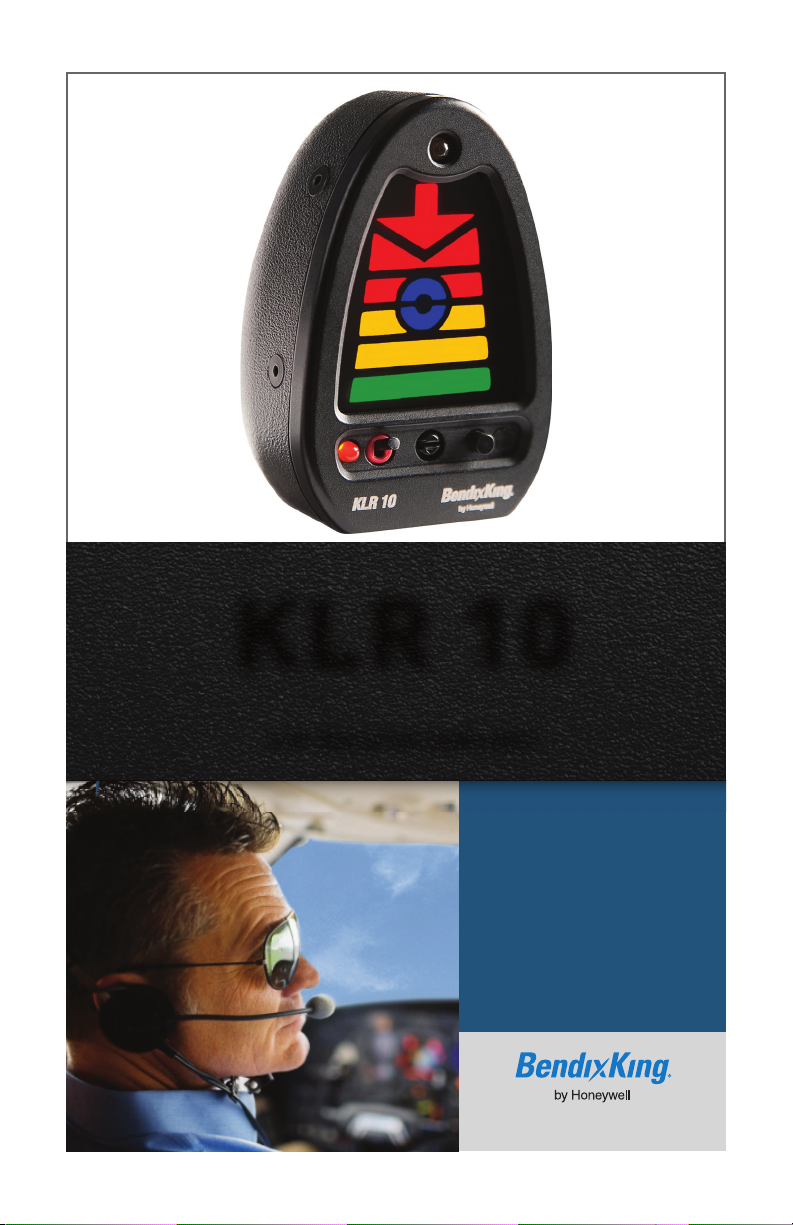
KLR 10
Lift Reserve Indicator
Pilot’s
Guide
BendixK ing.com
Page 2

information contained in the Airplane Flight Manual, the
information in the Airplane Flight Manual shall take
BendixKing by Honeywell
9201-B San Mateo Blvd. NE
Albuquerque, New Mexico 87112
Product Registration
For product registration go to BendixKing.com or call our
customer support number below.
Customer Support
US and Canada - 1.855.250.7027
International – 1.602.365.7027
bendixking.com/support
At BendixKing we value your opinion and we are listening. For
comments about this guide, please email:
techsupport@bendixking.com
The information contained in this manual is for reference
only. If any information contained herein conflicts with similar
precedence.
COPYRIGHT NOTICE
© 2013, 2014, BendixKing by Honeywell. All rights reserved.
Reproduction of this publication or any portion thereof by any
means without the express written permission of Honeywell
International Inc. is prohibited. See Appendix for complete
terms and conditions.
Page 3

KLR 10 Pilot’s Guide
KLR 10™
LIFT RESERVE
INDICATOR
PILOT’S GUIDE
P/N D201306000109 Title
Rev 1 Feb 2014 Page T-1
Page 4

KLR 10 Lift Reserve Indicator Pilot’s Guide
Revision History and Instructions
Manual KLR 10 Indicator Pilot’s Guide
Revision 1
Summary Revisions to various sentences for technical accuracy.
Removed Section 4.2 Honeywell Confidential.
Manual KLR 10 Indicator Pilot’s Guide
Revision 0
Summary This is a new release.
Record of Revisions
REVISION
NUMBER
0 JULY, 2013
1 FEBRUARY, 2014
REVISION
DATE
Title P/N D201306000109
Page T-2 Rev 1 Feb 2014
Page 5

KLR 10 Lift Reserve Indicator Pilot’s Guide
Table of Contents
Section Page
1. Introduction ............................................................................. 1-1
1.1 Background Information: ................................................. 1-1
1.2 System Description .......................................................... 1-1
1.3 Restrictions and Limitations ............................................ 1-2
2. KLR 10 Controls...................................................................... 2-1
2.1 Power Up Self Test .......................................................... 2-1
2.2 KLR 10 Indicator Main Controls ...................................... 2-1
2.3 The KLR 10 Display Segments: ...................................... 2-4
2.4 Display Brightness Calibration ........................................ 2-7
2.5 Brightness Adjustment when Active ................................ 2-8
2.6 In-Flight Calibration Flow Charts ..................................... 2-8
3. Operation ................................................................................. 3-1
3.1 Practice High AOA Flight Regime ................................... 3-2
Observed Indications ...................................................... 3-3
3.2 Practice Takeoff and Climb using AOA ........................... 3-7
Establish Segments Illuminated ...................................... 3-8
Fly Practice Takeoffs for Familiarization ......................... 3-9
Observed Indications .................................................... 3-10
3.3 Practice Best Glide speed ............................................. 3-11
Establish Segments Illuminated .................................... 3-11
3.4 Practice Approaches using AOA ................................... 3-13
Establish Segments Illuminated .................................... 3-14
Fly Practice Approaches for Familiarization.................. 3-15
Useful Techniques when using KLR 10 Indicator ......... 3-16
NOTES .......................................................................... 3-18
4. Appendix ................................................................................. 4-1
4.1 Acronyms and Abbreviations ........................................... 4-1
4.2 Copyright - Notice ............................................................ 4-3
P/N D201306000109 Table of Contents
Rev 1 Feb 2014 Page TC-1
Page 6

KLR 10 Pilot’s Guide
List of Illustrations
Figure Page
Figure 2-1: KLR-10 Indicator Controls ............................................ 2-1
Figure 2-2: OAA Setpoint Calibration .............................................. 2-9
Figure 2-3: Cruise Setpoint Calibration ......................................... 2-10
List of Tables
Table Page
Table 2-1: KLR 10 Indicator Control Switch Features .................... 2-2
Table 2-2: KLR 10 Indicator Segments ........................................... 2-4
Table 3-1: Observed Indications Chart ......................................... 3-17
Table of Contents P/N D201306000109
Page TC-2 Rev 1 Feb 2014
Page 7

KLR 10 Lift Reserve Indicator Pilot’s Guide
1. INTRODUCTION
1.1 BACKGROUND INFORMATION:
The KLR 10 system is primarily designed to improve the pilot's
awareness of available lift during operations at high angles of attack
(AOA). Additional benefits include identifying or maximizing aircraft
performance based on a fixed AOA or a constant CL, such as
maximum range, best glide, climbs and approaches.
AOA: Angle of Attack is the acute angle between the
wing chord line and the relative wind.
CL: Coefficient of Lift is a relative measure of an
airfoil’s lifting capabilities.
C
Lmax: Coefficient of Lift Maximum is the AOA which if
exceeded will cause the airfoil to stall.
C
D: Coefficient of Drag is a measure of total drag,
induced and parasite drag.
C
L/CD: Coefficient of Lift over Coefficient of Drag is a
ratio between lift and drag.
C
L/CD Maximum: The maximum lift-to-drag ratio at which
maximum range and maximum glide distance will
be found for propeller airplanes.
1.2 SYSTEM DESCRIPTION
The KLR 10 measures pressure at two points from an AOA probe
mounted solidly to the wing in reference to the cord of the wing that
conveys changing differential pressures, via sense lines, to the
KLR 10 IF module. The IF module converts the pressures into an
electronic signal that is transmitted to the KLR 10 indicator.
The KLR 10 indicator interprets the signal and turns on the
appropriate segments to convey the AOA or lift information to the
pilot. In addition to the visual display, the IF module also has an I/O
connector that allows connection of the remote audio interface
system that provides warning annunciations in the pilot’s headset.
P/N D201306000109 Introduction
Rev 1 Feb 2014 Page 1-1
Page 8

KLR 10 Pilot’s Guide
The KLR 10 draws a minimal current of less than approximately ¼
amp (250mA) of electrical power. For the system to operate
correctly, it must be supplied electrical power within a range of 12 to
28VDC and be calibrated correctly.
The AOA probe must be kept clear of any obstructions and be
mounted securely, in clean air flow. The final AOA probe to wing
angle will be determined by the amount the bottom of the wing varies
from parallel to the cord of the wing. For most aircraft, the starting
angle is 50 degrees from the leading edge of the AOA probe
mounting plate. The KLR 10 system will adjust for differences within
a limited electrical signal range. AOA Probe angle readjustment
may be needed to allow for full scale electronic calibration.
Probe heat is an option, and if installed, requires less than 8 amps of
electrical power at 12 or 24VDC to operate. To extend the life of the
probe heat element, it is recommended that the probe heat not be
used for prolonged periods while on the ground.
The KLR 10, when properly calibrated in accordance with the
BendixKing KLR 10 Installation Manual part number
D201305000058, will have an accuracy of ±3% over the full scale of
the calibration. This accuracy is maintained over a sideslip range of
±15 degrees.
1.3 RESTRICTIONS AND LIMITATIONS
The KLR 10 Lift Indicator is non-required and is to be used only as
supplemental information to the pilot.
The KLR 10 Lift Indicator may not be used as a substitution for the
certified aircraft stall warning system.
No operational credit may be taken for such items as reduced
approach speed and shorter landing distances.
Introduction P/N D201306000109
Page 1-2 Rev 1 Feb 2014
Page 9
KLR 10 Lift Reserve Indicator Pilot’s Guide
2. KLR 10 CONTROLS
2.1 POWER UP SELF TEST
When power is first applied to the KLR 10 (only after ground, OAA
and Cruise are fully calibrated per the Installation Manual), the
KLR 10 runs through a built in test. During the test, the segments
cycle up and then down the display. When the test is complete, the
segments turn off and the KLR 10 annunciates “AOA test complete”.
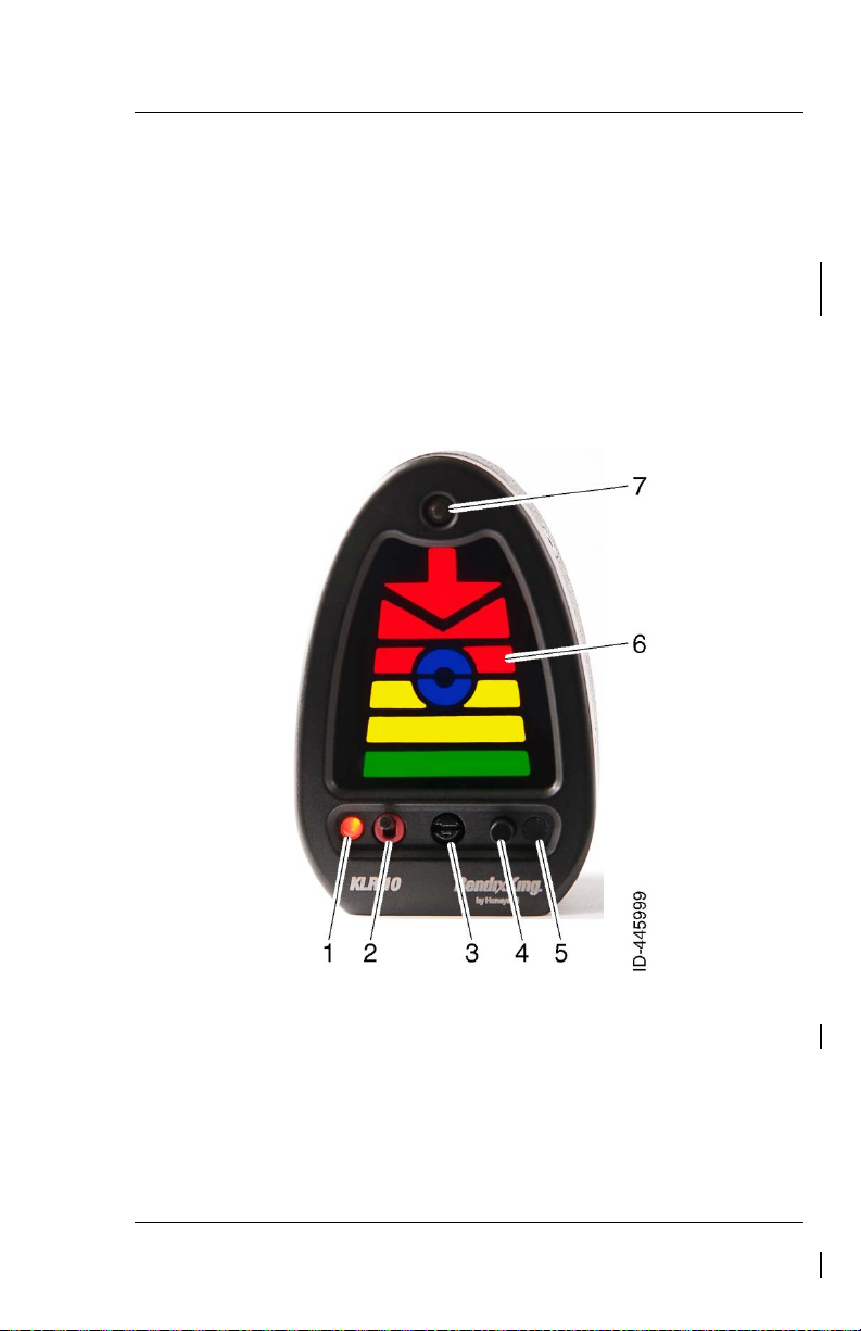
2.2 KLR 10 INDICATOR MAIN CONTROLS
Figure 2-1: KLR-10 Indicator Controls
Use the table below for a description of the functionality of the
controls in Figure 2-1
P/N D201306000109 KLR 10 Controls
Rev 1 Feb 2014 Page 2-1
Page 10

KLR 10 Pilot’s Guide
When the LED is illuminated, audio is
his switch
Rotary switch used to enter calibration
mode. When the slot is in the vertical
is activated. When the slot is turned to
mode button is pressed one time, the
calibration mode is exited and the
unit announces: “Calibration
Table 2-1: KLR 10 Indicator Control Switch Features
ITEM CONTROL FUNCTION
1 Audio “Mute”
Amber LED
muted. When the LED is not illuminated,
audio is not muted.
2 Audio “Mute”
Toggle Switch
3 Calibration
Mode Switch
In the UP position, this switch mutes the
audio and illuminates the amber LED (1)
on the KLR 10 indicator.
In the down position, t
activates the high AOA warning
annunciations and the amber LED (1) on
the KLR 10 indicator is not illuminated.
position and the brightness mode button
is pressed one time, the calibration mode
the horizontal position and the brightness
KLR 10
Mode Off”.
KLR 10 Controls P/N D201306000109
Page 2-2 Rev 1 Feb 2014
Page 11

KLR 10 Lift Reserve Indicator Pilot’s Guide
button on the lower right corner of the
the brightness levels of the
colored segments (Quickly push and
release to cycle thru 16 brightness
into and out of OAA and Cruise
calibration steps when the calibration
more information on how to set the
The calibration set push button is the
corner and is recessed underneath the
front case. The calibration set button is
used to enter selected calibration set
points (Ground Zero, OAA and Cruise)
during the calibration procedure. It can
Multicolored segments that correspond
to different angles of attack for the
display and automatically
ITEM CONTROL FUNCTION
4 Brightness /
MODE Push
Button Switch
(Multiple
Functions)
5 The “CAL
SET” push
button
The Brightness button is the black push
display.
The Brightness button has 2 functions:
Changes
levels),
Operates as a MODE switch, to enter
rotary switch is vertical. See page 2-7 for
Brightness levels.
black button located at the bottom right
be actuated using a pencil or other small
blunt pointer.
6 Display
Segments
aircraft.
7 Auto
Brightness
Photo Cell
The photo cell is in the top, middle of the
KLR 10
detects the ambient light changes which
will switch from daytime brightness
preset to nighttime brightness presets.
P/N D201306000109 KLR 10 Controls
Rev 1 Feb 2014 Page 2-3
Page 12
KLR 10 Pilot’s Guide
other segments indicates
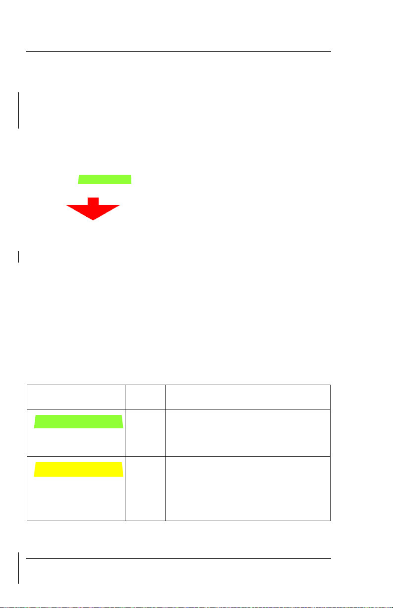
2.3 THE KLR 10 DISPLAY SEGMENTS:
The KLR 10 display has chevron and bar styled LED-driven colorcoded segments which, once correctly calibrated in accordance with
the BendixKing KLR 10 Installation Manual, part number
D201305000058, illuminate corresponding to the AOA of the aircraft.
The display will respond to the linear changes of the aircraft’s AOA
from Cruise, up to Stall and gives a repeatable, instantaneously
changing segment representation of that range. The display will
illuminate a series of transitional segments from no segments to the
Green Bar (“Cruise” indication for the aircraft located at
the bottom of the display), and on through to the flashing Red
Arrow “ ” (stall indication for the aircraft located at the
top of the display).
A correctly calibrated KLR 10 will provide a linear increase in AOA
indication as the aircraft slows. The final “Too slow Too slow” alert
with flashing red arrow MUST be active prior to the actual
aerodynamic stall. Ensure during post-calibration testing that the
final KLR 10 alert state is displayed prior to any stall indications.
The 10 possible segment combinations are listed below. Every
aircraft will correlate the lit segment or combination of segments to
the specific aircraft’s AOA dynamics, once calibrated. The
relationship of when and which combination shows is unique to the
aircraft’s AOA and can be accurately correlated ONLY when in-flight.
Table 2-2: KLR 10 Indicator Segments
SEGMENT ABBR CONDITION
G
Green Bar with no other segments
indicates Cruise set point, (lots of
lift).
Y1
Single lower Yellow Bar with no
slowing/moderate AOA.
KLR 10 Controls P/N D201306000109
Page 2-4 Rev 1 Feb 2014
Page 13

KLR 10 Lift Reserve Indicator Pilot’s Guide
segments indicates pattern
Single upper Yellow Bar with
segments indicates Optimum
with no other
segments indicates slightly
Red Bar with inverted Red
with no other segments
with inverted Red
with no other segments
indicates too slow (level 2) and
SEGMENT ABBR CONDITION
Y2
Double Yellow Bars with no other
entry/increasing AOA.
Y3
Single upper Yellow Bar with no
other segments indicates Base
leg/increasing AOA.
YB
Blue lower Half-Circle indicates
Final/slightly fast.
B
Blue Circle / Donut with no other
BR
Alpha Angle (AOA).
Single Red Bar with Blue upperHalf-Circle
slow/below OAA.
R1
Chevron
indicates too slow (level 1) KLR 10
annunciates “Check AOA”.
P/N D201306000109 KLR 10 Controls
Rev 1 Feb 2014 Page 2-5
R2
Red Arrow
Chevron
KLR 10 annunciates “Caution.
Too Slow”.
Page 14

KLR 10 Pilot’s Guide
, with no
other segments indicates critical
Too slow! Too
SEGMENT ABBR CONDITION
R3
Flashing Red Arrow
AOA (level 3) and KLR 10
annunciates “
slow!”
Note: No Segments illuminated = Power off OR very low speed
and lift state OR absence of pressure information to the
interface module OR aircraft on the ground with no
movement.
KLR 10 Controls P/N D201306000109
Page 2-6 Rev 1 Feb 2014
Page 15

KLR 10 Lift Reserve Indicator Pilot’s Guide
2.4 DISPLAY BRIGHTNESS CALIBRATION
The KLR 10 indicator is preset at the factory for daytime/nighttime
brightness levels. If the maximum/minimum brightness levels need to
be changed in your aircraft, do the following procedure to preset both
the daytime and nighttime display brightness levels while on the
ground.
Enter the Brightness calibration mode as follows:
• Ensure that power is not applied to the KLR 10.
• Depress and hold the Brightness button on the KLR 10
indicator then apply power to the KLR 10.
• Continue to depress the Brightness button until all segments
are illuminated.
• Release the Brightness button.
The system is now in Brightness calibration mode.
• With a light applied directly to the photo diode on the KLR 10
indicator for at least 5 seconds, press and release the
Brightness button until the display is at its maximum brightness.
Cycling past the maximum brightness of the colored segments will
cause the indicator to return to the minimum level. There are 16
brightness steps that are sequenced through, increasing brightness
at each step.
• Wait 5 seconds for the unit to store the setting then remove the
light from the KLR 10 indicator.
The display’s brightness will change to the lower brightness level
unless the low light setting was set to maximum brightness or the
cockpit is in daylight.
P/N D201306000109 KLR 10 Controls
Rev 1 Feb 2014 Page 2-7
Page 16

KLR 10 Pilot’s Guide
• Next, cover the photo diode on the display for at least 5 seconds
with your thumb or a piece of black electrical tape. Quickly press
and release the Brightness button on the KLR 10 indicator until
it’s at a minimum or lowest level.
• Wait 5 seconds for the unit to store the setting then remove your
thumb or the tape.
Observe that the display’s brightness level changes from dim to
bright when light is applied and removed from the photo diode. This
process takes about 5 seconds for the brightness level to change.
• Remove power, wait a few seconds and re-apply power.
On power up, if fully calibrated, the system will enter its self test,
display illumination routine in which all colored segments are
illuminated one by one upwards and then one by one downwards.
Otherwise, if OAA and Cruise still need to be calibrated, then the
blue and green segments will flash and then turn off.
2.5 BRIGHTNESS ADJUSTMENT WHEN ACTIVE
To change brightness when the unit is active, quickly push and
release the Brightness button until the desired brightness level is
reached.
There are 16 brightness levels and a photo cell to detect
“nighttime” and “daytime” ambient light levels and automatically
switches to the stored level. The new brightness levels are stored
when powered off.
2.6 IN-FLIGHT CALIBRATION FLOW CHARTS
The following flow charts contain an abbreviated version of the inflight calibration procedures. The complete in-flight calibration
procedures are contained in Section 5 of the KLR 10 Lift Reserve
Indicator Installation Manual, part number D201305000058.
It is highly recommended, to make calibration easier and safer, that
the pilot flies the aircraft while a second person follows the
calibration procedure and enters the appropriate set points for the
instrument.
CAUTION
At ALL times, the Pilot-in-Command must fly the aircraft in a
safe manner at altitude while maneuvering the aircraft in
slow flight.
KLR 10 Controls P/N D201306000109
Page 2-8 Rev 1 Feb 2014
Page 17
KLR 10 Lift Reserve Indicator Pilot’s Guide
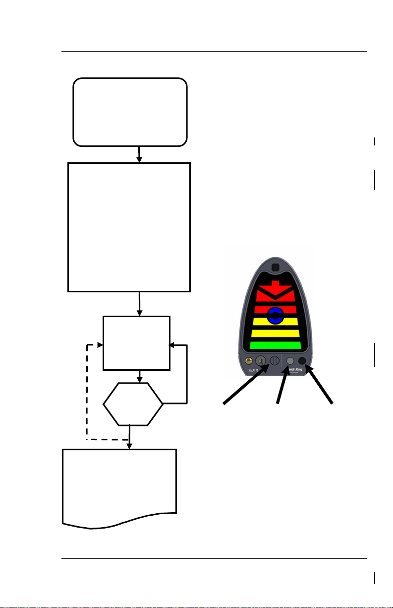
Good
point?
In-Flight calibration requires the pilot to climb to a
fly the aircraft to the condition of Optimum Alpha
Aircraft is at a safe altitude for slow flight
Minimum controllable flight, lower power
(such as a down wind or landing
ight control
, pilot to identify the set point by
able to hold altitude with full
been achieved, the pilot
enter into the Cruise Calibration
Mode or repeat the OAA Set
SET
BAD
To set an OAA,
STEP 1
SET POINT
Step C
at OAA.
Step A
Turn the Calibration Mode Switch so
. The
on the display
flashes three times, and the unit
flashes 2 times every five to six
seconds to indicate the unit is in
Step B
IN- FLIGHT
CALIBRATION of KLR 10
OPTIMUM ALPHA ANGLE
(OAA)
slot is vertical (Step A). Press the
Brightness button (Step B)
Blue Circle/Donut
announces “Calibration Mode On”.
The system has entered the OAA
set-point calibration mode.
Note: The Blue Circle/Donut
OAA set point calibration mode. The
system will remain at OAA Set Point
calibration mode until a valid value
has been entered.
quickly press and
release CAL SET
button (Step C).
safe altitude for slow flight maneuvers. The pilot will
Angle (OAA). Aircraft is at OAA, when:
1.)
maneuvers.
2.)
setting
pattern power setting).
3.) Able to hold altitude, 0 Vertical Speed, not
descending, zero sink (5 to 10 fpm climb
OK if your aircraft loses fl
stability at 0 VS).
4.) Full aileron, elevator and rudder control, not in
a buffet
pitching back slowly to a pitch no longer able
to climb but
control of the airplane.
OAA Set
Once a good OAA Set point has
continues to STEP 2 and MUST
point Operation.
P/N D201306000109 KLR 10 Controls
Rev 1 Feb 2014 Page 2-9
Turn the
Calibration
Mode Switch
so slot is
vertical.
Press the
brightness
button.
Press and
release CAL
SET button
to calibrate
when flying
Figure 2-2: OAA Setpoint Calibration
Page 18

KLR 10 Pilot’s Guide
Good Cruise
The pilot must fly the aircraft at a
flight condition, straight
power. This procedure sets the
the aircraft.
After the OAA set point is set successfully:
flashes 2 times
every five to six seconds indicating that the
unit is in Cruise Set Point calibration mode.
setting is entered and OAA and Cruise
Operational Mode
SET
BAD
To set the Cruise
Good Set point:
storing the values, putting the
system in functional mode.
Bad Set point:
flashes 3
times and unit announces:
GOOD
To exit and store the set points (OAA
and Cruise) to memory, turn the
calibration mode switch so that the
slot is horizontal. Then press the
Note:
The KLR 10 instrument display’s
STEP A
STEP B
STEP 2
IN- FLIGHT CALIBRATION
of KLR 10 CRUISE
SET POINT
Do not adjust the Calibration Mode Switch.
Press the brightness button to enter the Cruise
Set Point calibration mode (Step A). The KLR
10 Display flashes the Green Bar three times
and there is no audio announcement. The
system has entered the Cruise Set point
Calibration mode.
NOTE: The GREEN BAR
Unit will stay in this mode until a valid cruise
calibration mode is exited.
Set point, quickly
press and release
CAL SET button
(step B).
Set point?
AGAIN?
“Cruise” Inand level, holding altitude at Cruise
display to indicate “Cruise” AOA for
Press the brightness
Button. The Green Bar
flashes three times,
there is no audio
announcement.
The GREEN BAR
“Invalid Set Point”.
The GREEN BAR is displayed and
unit announces: “Cruise Alpha
Calibration Set”. The operator can
set it again or exit calibration Mode,
Quickly press
and release CAL
SET button
when flying at
“Cruise”.
If the Setting is NOT Successful:
The KLR 10 display returns to an
brightness mode push button.
(This completes calibration)
Pilot to identify other
aircraft in-flight values.
operational state and discards the
attempted set point (Values out of
range).
AND
Green Bar flashes three times and
announces “Invalid Set Point”.
Figure 2-3: Cruise Setpoint Calibration
KLR 10 Controls P/N D201306000109
Page 2-10 Rev 1 Feb 2014
Page 19

KLR 10 Lift Reserve Indicator Pilot’s Guide
3. OPERATION
The KLR 10 Lift Reserve Indicator improves pilot awareness of
available lift during operation at high angles of attack such as slow
flight, takeoffs and landings.
The system is calibrated with the aircraft in the clean configuration.
When flaps are extended, the KLR 10 AOA indications will be more
conservative (showing higher AOA).
This section explains the procedures to be flown to develop a
reference list that shows the segments that are lit on the KLR 10
Indicator during the different phases of flight.
Section 3.1 on page 3-2 gives the procedure to practice a high AOA
flight regime with the use of the KLR 10 Indicator.
Section 3.2 on page 3-7 gives the procedures to practice takeoffs
and climb outs with the use of the KLR 10 Indicator.
Section 3.3 on page 3-11 gives the procedures to maintain best glide
speed with the use of the KLR 10 Indicator.
Section 3.4 on page 3-13 gives the procedures to practice
approaches with the use of the KLR 10 Indicator.
P/N D201306000109 Operation
Rev 1 Feb 2014 Page 3-1
Page 20

KLR 10 Pilot’s Guide
3.1 PRACTICE HIGH AOA FLIGHT REGIME
To familiarize you with the KLR 10 indications during a high AOA
flight regime, use the following outline as a guide:
• Plan a flight to an area where high AOA flight can be performed
without any undue hazards (reference § 91.303 & § 91.305).
• Review the stall recovery procedures for your aircraft. If an
inadvertent stall occurs, immediately recover from the stall per
your training and the aircraft manufacturers instructions. At no
time is a stall required to correctly calibrate or operate the KLR
10.
• Acquaint yourself with the KLR 10 indicator and its functions.
• Preflight and operate the aircraft as you would normally.
• When in an area and at a safe altitude that safe operation at
slow flight can be performed and the air is smooth, perform
clearing turns to ensure the area is clear.
• Follow the aircraft procedures and slow the aircraft, in the clean
configuration (No Flaps).
• Maintain coordination.
• Maintain altitude.
• Monitor the KLR 10 indicator.
• Slow to just above the stall. If any stall warning device activates
or an impending aerodynamic stall is imminent, recover
immediately using the appropriate procedure for your aircraft.
• Return to normal flight.
• Using the abbreviations from Table 2-2 on page 2-4, write down
the illuminated segments in the space provided below and in the
Table 3-1: Observed Indications Chart on page 3-17.
Operation P/N D201306000109
Page 3-2 Rev 1 Feb 2014
Page 21

KLR 10 Lift Reserve Indicator Pilot’s Guide
The colored segments on the AOA indicator
Start your recovery from the high AOA flight
flashing Red
If any stall warning device activates or
an impending aerodynamic stall is
Observed Indications
As the aircraft slows and the AOA increases, note the following:
transitions from the Green Bar (G) segment
(Cruise) up through to the flashing Red arrow
(R3) segment.
A “Check AOA” warning annunciates as the
AOA increases and the Red Bar with inverted
Red Chevron (R1) segment is displayed.
A “Caution, Too Slow” warning annunciates
when the AOA increases more and the Red
Arrow with inverted Red Chevron (R2)
segment is displayed.
regime when the “Too slow! Too slow!”
warning annunciates and the
arrow is displayed.
Note:
imminent, recover immediately using the
appropriate procedure for your aircraft.
P/N D201306000109 Operation
Rev 1 Feb 2014 Page 3-3
Page 22

KLR 10 Pilot’s Guide
The AOA indicator transitions from the
The colored segments on the AOA indicator
(G) segment
annunciates as the
As the recovery progresses:
flashing Red Arrow segment through the Blue
Circle (B) segment and continues through the
Yellow Bars (Y2) segment until finally the
Green Bar (G) segment (Cruise) is illuminated.
Follow the outline above again but perform the high AOA flight
regime in the landing configuration (dirty) and observe the following:
transitions from the Green Bar
(Cruise) up through to the flashing Red Arrow
(R3) segment.
A “Check AOA” warning
AOA increases and the Red Bar with inverted
Red Chevron (R1) segment is displayed.
A “Caution, Too Slow” warning annunciates
when the AOA increases more and the Red Bar
with inverted Red Chevron (R2) segment is
displayed.
Operation P/N D201306000109
Page 3-4 Rev 1 Feb 2014
Page 23

Start your recovery from the high AOA flight
flashing Red
If any stall warning device activates or
an impending aerodynamic stall is
The lower the segments, from
regime when the “Too slow! Too slow!”
warning annunciates and the
arrow is displayed.
Note:
imminent, recover immediately using the
appropriate procedure for your aircraft.
As the recovery progresses:
The AOA indicator transitions through the blue
circle segment, Yellow Bars segment, to
finally the Green Bar segment (cruise, lots of
lift).
KLR 10 Lift Reserve Indicator Pilot’s Guide
Increasing
Lift
P/N D201306000109 Operation
Rev 1 Feb 2014 Page 3-5
flashing Red Arrow (R3)
segment, Blue Circle (B)
segment, Yellow Bar (Y1)
segment and to the Green Bar (G)
segment, the more the lift (lower
AOA).
Page 24

KLR 10 Pilot’s Guide
Practice until you become familiar with the indications on the AOA
and the relationship of your airspeed indicator. Since the airfoil on
your aircraft will ALWAYS stall at the same AOA (regardless of
weight) the AOA indications will be the same every time.
Operation P/N D201306000109
Page 3-6 Rev 1 Feb 2014
Page 25

KLR 10 Lift Reserve Indicator Pilot’s Guide
3.2 PRACTICE TAKEOFF AND CLIMB USING AOA
The use of AOA for takeoff and climb performance will greatly
increase the pilot’s awareness while operating at high angles of
attack and yield safe and consistent results.
For example, if you intend to perform a short field over an obstacle
takeoff there are a number of factors you must consider to arrive at
the proper indicated airspeed for the climb. Changing gross weight,
pressure, altitude and temperature will all have an effect on the
indicated climb speed. On the other hand, once you establish the
correct AOA for the climb, it will be the same regardless of the
factors previously mentioned.
To determine the correct AOA for a climb we need a baseline to start
from. For this example we will figure it out for Vx (best angle of
climb). Some aircraft may use two different speeds based on the
aircraft configuration, let’s use the one for clearing an obstacle on
takeoff. Refer to the aircraft manual to determine the configuration
and airspeed for V
• Identify actual gross weight.
• Pressure altitude, at the demonstration altitude.
• Temperature, at the demonstration altitude.
x considering the following factors:
• Correct Calibrated Air Speed (CAS) for installation errors to
arrive at Indicated Air Speed (IAS).
P/N D201306000109 Operation
Rev 1 Feb 2014 Page 3-7
Page 26

KLR 10 Pilot’s Guide
Establish Segments Illuminated
As before, to familiarize you with the KLR 10 indications for Vx use
the following outline as a guide:
• Plan a flight to an area where the desired maneuvers may be
performed without any undue hazards.
• Acquaint yourself with the KLR 10 indicator.
• Preflight and operate the aircraft as you would normally.
• When in the area, perform clearing turns to ensure the area is
clear.
• Maintain coordination and altitude.
• Use power to slow and configure for V
• Maintain the indicated airspeed for V
x.
x.
• Observe the KLR 10 AOA indication and make a mental note.
• Return to normal flight.
• Using the abbreviations from Table 2-2 on page 2-4, write down
the illuminated segments in the space provided below and in the
Table 3-1: Observed Indications Chart on page 3-17.
Segments Illuminated:
This AOA indication is accurate for future use at any gross weight or
altitude, every time. Also, this same method may be used to
determine the AOA for any climb. Now try it for Vy, best rate of climb,
using the procedure described above.
Operation P/N D201306000109
Page 3-8 Rev 1 Feb 2014
Page 27

KLR 10 Lift Reserve Indicator Pilot’s Guide
Fly Practice Takeoffs for Familiarization
Now practice the use of the AOA for takeoff at airports that give you
a comfortable margin. Then when you perfect the technique you can
perform short field over an obstacle takeoffs safely. Use the following
outline as a guide.
• Review your aircraft procedures for short field over an obstacle
takeoff.
• Plan for a flight at an airport where normal takeoffs and landing
may be performed.
• Preflight and operate the aircraft as you would normally.
• Perform the takeoff run as specified in the aircraft manual.
• At the specified takeoff speed, rotate smoothly to the AOA for
Vx.
CAUTION
Do not over rotate or rotate too rapidly as either will cause
catastrophic results.
• When well above the obstacle, decrease the AOA and clean
up on schedule.
• Adjust the pitch to achieve the AOA for Vy and continue the
climb.
• Return to normal flight.
• Using the abbreviations from Table 2-2 on page 2-4, write
down the illuminated segments in the space provided below
and in the Table 3-1: Observed Indications Chart on page 3-
17.
Segments Illuminated:
P/N D201306000109 Operation
Rev 1 Feb 2014 Page 3-9
Page 28

KLR 10 Pilot’s Guide
segment, through to
Observed Indications
As the aircraft accelerates down the runway,
the KLR 10 AOA indicator will start to illuminate
with the flashing Red Arrow (R3) segment,
then top half of the single Red Bar with Blue
upper Half Circle (BR)
the combination of single upper Yellow Bar
with Blue lower Half-Circle (YB) segments,
then just to the Yellow Bars (Y2) segment.
When the pitch is rotated up, the AOA indication will move towards
V
x. Adjust the pitch to maintain the Vx angle.
To accelerate and clean up, the pitch is lowered, thus lowering the
AOA, decreasing induced drag and increasing lift. This allows the
aircraft to accelerate so the flaps can be retracted and the changes
in AOA can be observed.
Operation P/N D201306000109
Page 3-10 Rev 1 Feb 2014
Page 29

KLR 10 Lift Reserve Indicator Pilot’s Guide
3.3 PRACTICE BEST GLIDE SPEED
As mentioned earlier, the AOA may be used for identifying aircraft
performance based on a fixed AOA or a constant CL. For this
discussion C
L/CD Maximum indication will be identified. This is the
maximum lift-to-drag ratio at which maximum range and maximum
glide distance will be found for propeller airplanes.
To find the AOA for best glide, calculate an indicated airspeed
considering:
• Actual gross weight.
• Pressure altitude, at the demonstration altitude.
• Temperature, at the demonstration altitude.
• Correct CAS for installation errors to arrive at IAS.
Establish Segments Illuminated
As before, to familiarize you with the KLR 10 AOA indications for
L/CD Maximum, use the following outline as a guide:
C
• Plan a flight to an area where the desired maneuvers may be
performed without any undue hazards.
• Acquaint yourself with the KLR 10 display AOA indicator.
• Preflight and operate the aircraft as you would normally.
• When in the area, perform clearing turns to ensure the area is
clear.
• Maintain coordination.
• Maintain altitude.
• Use power to slow and maintain best glide speed.
• Observe the KLR 10 display AOA indication; this is C
L/CD
Maximum.
• Return to normal flight.
• Using the abbreviations from Table 2-2 on page 2-4, write down
the illuminated segments in the space provided below and in the
Table 3-1: Observed Indications Chart on page 3-17.
P/N D201306000109 Operation
Rev 1 Feb 2014 Page 3-11
Page 30

KLR 10 Pilot’s Guide
Segments Illuminated:
This AOA indication will be correct for future use at any gross weight
and/or altitude, every time. Document the angles of attack by the
segments illuminated in a permanent record for future use.
Example: Best Glide = single upper Yellow Bar with
Blue lower Half Circle (YB) segment being illuminated.
The methods used to arrive at this AOA indication are the same for
all constant AOA or C
L maneuvers.
Operation P/N D201306000109
Page 3-12 Rev 1 Feb 2014
Page 31

KLR 10 Lift Reserve Indicator Pilot’s Guide
3.4 PRACTICE APPROACHES USING AOA
A rule of thumb is to use an approach speed of 1.3 times the power
off stall speed in the landing configuration. Another rule of thumb is
in gusty winds add 5kts for one passenger and if it’s really gusty add
10kts for several passengers. While flying the approach at higher
speeds seems to be safer, having additional speed and kinetic
energy on a short runway may not be in the best interest of said
passengers. With the means to accurately know and control the AOA
you can fly a more stable approach and land with less kinetic energy
for any given situation than flying arbitrary approach speeds. Flying
an approach and landing using an AOA indicator may be a safer
procedure.
The AOA has been calibrated for an AOA just slightly less than
LMAX; however an acceptable margin above that angle to fly
C
approach and landings has not been determined. As a starting point,
use the aircraft manual to determine the stall speed of the aircraft at
the actual gross weight in the landing configuration. Take that
calibrated airspeed and multiply it by 1.3, 1.2 and 1.1. Then refer to
the airspeed correction chart to determine the correction, if any, to
convert from calibrated airspeed to indicated airspeed for the three
speeds. For example:
Calibrated Stall Speed X 1.3 = App. CAS ± the correction = App. IAS
58 kts CAS X 1.3 = 75.4 kts CAS + 2 kts correction = 77 kts IAS
58 kts CAS X 1.2 = 69.6 kts CAS + 3 kts correction = 73 kts IAS
58 kts CAS X 1.1 = 63.8 kts CAS + 4 kts correction = 68 kts IAS
For ease of discussion, let’s call these speeds and the resulting AOA
indication as 3, 2 and 1 respectively. Once the AOA angles have
been identified, they will be accurate at any gross weight, every
time.
P/N D201306000109 Operation
Rev 1 Feb 2014 Page 3-13
Page 32

KLR 10 Pilot’s Guide
Establish Segments Illuminated
To establish the AOA indications for approaches, use the following
outline as a guide:
• Plan a flight to an area where approaches and slow flight can be
performed without any undue hazards (reference § 91.303 & §
91.305).
• Review the stall recovery procedures for your aircraft in case of
an inadvertent stall. If an inadvertent stall occurs, immediately
recover from the stall per your training and the aircraft
manufacturer's instructions. At no time is a stall required to
correctly calibrate or operate the KLR 10.
• Acquaint yourself with the KLR 10 display AOA indicator.
• Preflight and operate the aircraft as you would normally.
• When in an area where approaches and slow flight can be
performed and the air is smooth, perform clearing turns to
ensure the area is clear.
• Follow the aircraft procedures, slow and configure to the landing
configuration.
• Maintain coordination.
• Maintain altitude with the pitch (use pitch trim to relieve back
pressure).
• Use power as needed to maintain flight at the first of the
calculated approach speeds, “3”.
• Write down the colored segments illuminated. ___________
• Use power as needed to slow to and maintain flight at the
second of the calculated approach speeds, “2”.
• Write the new segments illuminated. ___________
• Use power as needed to slow to and maintain flight at the third
of the calculated approach speeds, “1”.
• Return to normal flight.
• Write the new segments illuminated. ___________
• Write the segments illuminated for the 3 approaches in the Table
3-1: Observed Indications Chart on page 3-17.
Operation P/N D201306000109
Page 3-14 Rev 1 Feb 2014
Page 33

KLR 10 Lift Reserve Indicator Pilot’s Guide
Fly Practice Approaches for Familiarization
To familiarize you with the aircraft while flying practice approaches
using the KLR 10 Indicator as a guide, please use the following
outline:
• Plan a flight to an area where approaches and slow flight can be
performed without any undue hazards (reference § 91.303 & §
91.305).
• Review the stall recovery procedures for your aircraft.
• Acquaint yourself with the KLR 10 indicator.
• Preflight and operate the aircraft as you would normally.
• When in an area where approaches and slow flight can be
performed and the air is smooth, perform clearing turns to
ensure the area is clear.
• Follow the aircraft procedures, slow and configure to the landing
configuration.
• Maintain coordination.
• Set the power as you would to fly a normal approach.
• Maintain altitude with the pitch until the AOA approaches the “3”
indication. Lower and use pitch to maintain that AOA (use pitch
trim to relieve back pressure).
• Fly the aircraft in the descent (straight & turning), pay attention
to the flight control effectiveness.
• Perform a recovery from the high AOA condition prior to any
aerodynamic or aural/visual stall warning using the
manufacturer’s instructions for your aircraft.
• Climb back to the initial altitude.
P/N D201306000109 Operation
Rev 1 Feb 2014 Page 3-15
Page 34

KLR 10 Pilot’s Guide
Repeat the steps above using AOA indications “2” and “1”. Gain
experience by practicing these simulated approaches and landings
using the AOA indicator.
Some notable observations:
• The control effectiveness decreases with higher AOA.
• The higher the AOA, the more attention has to be given to
rudder inputs to compensate for adverse yaw.
• Approaches at the higher angles of attack leaves little time
between starting the flair and stall.
Useful Techniques when using KLR 10 Indicator
Some techniques and things to consider when using the KLR 10
Indicator to fly approaches are:
• Coordinate the use of pitch and power to fly the approach and
landing.
• Use PITCH primarily to control the AOA.
• Use POWER primarily to control the descent rate.
• Keep in mind how much power it took to just maintain altitude.
• A stable approach all the way to the runway is much safer than
making radical changes to the AOA or descent rate once an
obstacle is cleared.
• Set a safe standard for yourself using all your experience to set
a maximum AOA for any approach and do not let pressures
cause you to fly an approach at too high of AOA.
• When flying in gusty conditions fly a lower AOA so that when a
wind gust changes your AOA it does not exceed your maximum
AOA.
• Having a great new system to indicate AOA does NOT change
the laws of physics, use it as a new tool to fly safe.
Operation P/N D201306000109
Page 3-16 Rev 1 Feb 2014
Page 35

KLR 10 Lift Reserve Indicator Pilot’s Guide
High AOA
Best Glide
Write down the actual indications you observe on the KLR 10
Indicator as you conduct the different phases of flight.
Table 3-1: Observed Indications Chart
Segment
Illuminated
ABBR
R3
R2
R1
BR
B
YB
Y3
Y2
Y1
Phase of
Flight
(pre-stall)
Climb Vx
Climb Vy
Cruise
Speed
Approaches
1.3 Vs
1.2 Vs
1.1 Vs
Flaps
Up
(Clean)
Flaps
Down
(Dirty)
P/N D201306000109 Operation
Rev 1 Feb 2014 Page 3-17
G
Page 36

KLR 10 Pilot’s Guide
NOTES
Operation P/N D201306000109
Page 3-18 Rev 1 Feb 2014
Page 37

KLR 10 Lift Reserve Indicator Pilot’s Guide
4. APPENDIX
4.1 ACRONYMS AND ABBREVIATIONS
Acronyms and abbreviations used in this manual are defined as
follows:
TERMS DEFINITION
AOA Angle of Attack
CAS Calibrated Air Speed
CL Coefficient of Lift
CLmax Coefficient of Lift Maximum
CD Coefficient of Drag
CL/CD Coefficient of Lift over Coefficient of Drag
FAA Federal Aviation Administration
IF module Interface Module
IA Inspection Authorization
IAS Indicated Air Speed
kts Nautical miles per hour
MAC Mean Aerodynamic Cord ()
OAA Optimum Alpha Angle
Vs Stall Speed – clean
Vx Speed that allows for best angle of climb
P/N D201306000109 Appendix
Rev 1 Feb 2014 Page 4-1
Page 38

KLR 10 Pilot’s Guide
TERMS DEFINITION
Vy Speed that allows for the best rate of climb
Appendix P/N D201306000109
Page 4-2 Rev 1 Feb 2014
Page 39

KLR 10 Lift Reserve Indicator Pilot’s Guide
4.2 COPYRIGHT - NOTICE
Copyright 2013, 2014, Honeywell International Inc. All rights
reserved.
Honeywell is a registered trademark of Honeywell International
Inc.
All other marks are owned by their respective companies.
P/N D201306000109 Appendix
Rev 1 Feb 2014 Page 4-3
 Loading...