

Page 1
KLN 90B
Bendix/King
®
TSO’d GPS Navigation System
Pilot’s Guide
ORS 20
A
Page 2

A
AlliedSignal, Inc.
Commercial Avionics Systems
400 North Rogers Road
Olathe, Kansas 66062-1294
FAX 913-791-1302
Telephone: (913) 782-0400
006-08773-0000
Rev.1 05/97
Page 3

i
Rev 1
KLN 90B PILOT’S GUIDE
006-08773-0000
for KLN 90Bs with
OPERATIONAL REVISION STATUS (ORS) 20
May, 1997
IMPORTANT:
Special installation procedures must be
follow ed in order for the KLN 90B to be certified for IFR use.
Consult the KLN 90B Flight Manual Supplement for the
operating limitations of this unit.
For Important
Database Update
Information
See Section 2.7
Page 4

ii
Rev 1
THIS PAGE INTENTIONALLY LEFT BLANK
Page 5

TOC-1
Rev 1
INTRODUCTION ...........................................................................................................................................................I
PREVIEW OF OPERATION............................................................................................................................................II
CHAPTER 1 - KLN 90B SYSTEM COMPONENTS....................................................................................................1-1
CHAPTER 2 - DATA BASE.........................................................................................................................................2-1
2.1 FUNCTIONS OF THE DATA BASE .................................................................................................................2-1
2.2 DATA BASE COVERAGE AREAS AND CONTENTS ..................................................................................2-1
2.3 USE OF ICAO IDENTIFIERS ...........................................................................................................................2-3
2.4 UPDATING THE DATABASE ..........................................................................................................................2-3
2.4.1 Computer Updating of the Database ..................................................................................................2-4
2.4.2 Cartridge Exchange Updating of the Database ..................................................................................2-7
2.5 USER DEFINED DATABASE ..........................................................................................................................2-8
2.6 INTERNAL MEMORY BACKUP BATTERY ....................................................................................................2-8
2.7 DATABASE UPDATE SERVICE OPTIONS.....................................................................................................2-8
CHAPTER 3 - LEVEL 1 OPERATION.........................................................................................................................3-1
3.1 COVERAGE AREA ..........................................................................................................................................3-1
3.2 TURN-ON AND SELF TEST ............................................................................................................................3-3
3.3 DISPLAY FORMAT ..........................................................................................................................................3-9
3.4 BASIC OPERATION OF PANEL CONTROLS ..............................................................................................3-11
3.4.1 Page Selection ..................................................................................................................................3-12
3.4.2 Data Entry .........................................................................................................................................3-14
3.4.3 Alternative Waypoint Data Entry Method .........................................................................................3-15
3.4.4 The Duplicate Waypoint Page ..........................................................................................................3-15
3.5 MESSAGE PAGE ...........................................................................................................................................3-16
3.6 INITIALIZATION AND TIME TO FIRST FIX ..................................................................................................3-17
3.7 SELECTING WAYPOINTS ............................................................................................................................3-20
3.7.1 Selecting Waypoints By Identifier .....................................................................................................3-20
3.7.2 Selecting Waypoints By Scanning ....................................................................................................3-21
3.7.3 “Nearest” And “Complete” Waypoint Scan Lists ..............................................................................3-22
3.7.3.1 Nearest Airports In An Emergency ...............................................................................................3-23
3.7.3.2 Continuous Display Of Nearest Airport .........................................................................................3-24
3.7.4 Selecting Waypoint By Name Or City ...............................................................................................3-24
3.8 DIRECT TO OPERATION ..............................................................................................................................3-27
3.8.1 Direct To-Procedure 1 ......................................................................................................................3-28
3.8.2 Direct To-Procedure 2 ......................................................................................................................3-28
3.8.3 To Recenter The D-Bar ....................................................................................................................3-29
3.8.4 To Proceed Direct To Another Waypoint .........................................................................................3-29
3.8.5 Cancelling Direct To Operation ........................................................................................................3-29
3.8.6 Waypoint Alerting For Direct To Operation ......................................................................................3-29
3.9 THE NAVIGATION PAGES ...........................................................................................................................3-31
3.9.1 The Navigation 1 Page (NAV 1) .......................................................................................................3-31
3.9.2 The Super NAV 1 Page ...................................................................................................................3-32
3.9.3 The Navigation 2 Page (NAV 2) .......................................................................................................3-32
3.9.4 The Navigation 3 Page (NAV 3) .......................................................................................................3-32
3.9.5 The Navigation 4 Page (NAV 4) .......................................................................................................3-34
3.9.6 The Navigation 5 Page (NAV 5) .......................................................................................................3-34
3.9.7 The Super NAV 5 Page ....................................................................................................................3-36
3.10 SPECIAL USE AIRSPACE ALERT ..............................................................................................................3-39
TABLE OF CONTENTS
Page 6

TOC-2
Rev 1
3.11 VIEWING THE WAYPOINT PAGES ...........................................................................................................3-42
3.11.1 Airport Pages ..................................................................................................................................3-42
3.11.2 The Airport 1 Page (APT 1) ............................................................................................................3-42
3.11.3 The Airport 2 Page (APT 2) ............................................................................................................3-43
3.11.4 The Airport 3 Page (APT 3) ............................................................................................................3-43
3.11.5 The Airport 4 Page (APT 4) ............................................................................................................3-45
3.11.6 The Airport 5 Page (APT 5) ............................................................................................................3-47
3.11.7 The Airport 6 Page (APT 6) ............................................................................................................3-48
3.11.8 The Airport 7 Page (APT 7) ............................................................................................................3-49
3.11.9 The Airport 8 Page (APT 8) ............................................................................................................3-49
3.11.10 The VOR Page .............................................................................................................................3-49
3.11.11 The NDB Page ..............................................................................................................................3-50
3.11.12 The Intersection Page (INT) .........................................................................................................3-50
3.11.13 The Supplemental Waypoint Page (SUP) ....................................................................................3-51
3.12 FREQUENCIES FOR NEAREST FLIGHT SERVICE STATIONS ..............................................................3-52
3.13 FREQUENCIES FOR AIR ROUTE TRAFFIC CONTROL CENTERS (ARTCC) .......................................3-52
3.14 VIEWING AND SETTING THE DATE AND TIME .......................................................................................3-53
3.15 ALTITUDE ALERTING .................................................................................................................................3-55
3.16 HEIGHT ABOVE AIRPORT ALERT ............................................................................................................3-58
3.17 REMOTE MOUNTED ANNUNCIATORS ....................................................................................................3-59
3.18 SAMPLE TRIP ..............................................................................................................................................3-60
3.18.1 Pre-Departure .................................................................................................................................3-60
3.18.2 Enroute ...........................................................................................................................................3-60
3.18.3 Terminal Area .................................................................................................................................3-61
CHAPTER 4 - LEVEL 2 OPERATION.........................................................................................................................4-1
4.1 CREATING AND MODIFYING FLIGHT PLANS .............................................................................................4-1
4.1.1 Creating A Flight Plan .........................................................................................................................4-2
4.1.2 Activating A Numbered Flight Plan .....................................................................................................4-3
4.1.3 Adding A Waypoint To A Flight Plan ..................................................................................................4-4
4.1.4 Deleting A Waypoint From A Flight Plan ............................................................................................4-5
4.1.5 Deleting Flight Plans ...........................................................................................................................4-5
4.1.6 Storing FPL 0 As A Numbered Flight Plan .........................................................................................4-6
4.2 OPERATING FROM THE ACTIVE FLIGHT PLAN .........................................................................................4-7
4.2.1 General Procedures ............................................................................................................................4-7
4.2.2 Turn Anticipation And Waypoint Alerting ............................................................................................4-8
4.2.3 Viewing The Waypoint Pages For The Active Flight Plan Waypoints .............................................4-10
4.2.4 Combining Direct To And Flight Plan Operation ..............................................................................4-10
4.2.5 The Distance/Time Pages ................................................................................................................4-11
4.2.6 The Distance/Time 1 Page (D/T 1) ...................................................................................................4-11
4.2.7 The Distance/Time 2 Page (D/T 2) ...................................................................................................4-12
4.2.8 The Distance/Time 3 Page (D/T 3) ...................................................................................................4-12
4.2.9 The Distance/Time 4 Page (D/T 4) ...................................................................................................4-13
4.3 SAMPLE TRIP ................................................................................................................................................4-15
4.3.1 Pre-Departure ...................................................................................................................................4-16
4.3.2 Enroute ..............................................................................................................................................4-16
CHAPTER 5 - LEVEL 3 OPERATION.........................................................................................................................5-1
5.1 TRIP PLANNING ..............................................................................................................................................5-1
5.1.1 The Trip Planning 0 Page (TRI 0) .......................................................................................................5-2
5.1.2 The Trip Planning 1 And Trip Planning 2 Pages (TRI 1 and TRI 2) ..................................................5-3
5.1.3 The Trip Planning 3 And Trip Planning 4 Pages (TRI 3 and TRI 4) ..................................................5-5
Page 7

TOC-3
Rev 1
5.1.4 The Trip Planning 5 And Trip Planning 6 Pages (TRI 5 and TRI 6) ..................................................5-6
5.2 ADVISORY VNAV OPERATION .....................................................................................................................5-7
5.2.1 VNAV For Direct To Operation ...........................................................................................................5-7
5.2.2 VNAV For Flight Plan Operation .........................................................................................................5-9
5.2.3 VNAV From the Super NAV 5 Page ...................................................................................................5-9
5.3 CALCULATOR PAGES ..................................................................................................................................5-10
5.3.1 The Calculator 1 Page (CAL 1) ........................................................................................................5-10
5.3.2 The Calculator 2 Page (CAL 2) ........................................................................................................5-11
5.3.3 The Calculator 3 Page (CAL 3) ........................................................................................................5-12
5.3.4 The Calculator 4 Page (CAL 4) ........................................................................................................5-12
5.3.5 The Calculator 5 Page (CAL 5) ........................................................................................................5-13
5.3.6 The Calculator 6 Page (CAL 6) ........................................................................................................5-14
5.3.7 The Calculator 7 Page (CAL 7) ........................................................................................................5-15
5.4 USER-DEFINED WAYPOINTS .....................................................................................................................5-16
5.4.1 Creating An Airport User Waypoint ..................................................................................................5-16
5.4.2 Creating A VOR User Waypoint .......................................................................................................5-18
5.4.3 Creating An NDB User Waypoint .....................................................................................................5-18
5.4.4 Creating Intersection Or Supplemental User Waypoints .................................................................5-18
5.4.5 Deleting User-Defined Waypoints ....................................................................................................5-20
5.5 REFERENCE WAYPOINTS ..........................................................................................................................5-21
5.6 CENTER WAYPOINTS ..................................................................................................................................5-25
5.6.1 Creating Center Waypoints And Inserting Them in Flight Plans ......................................................5-25
5.6.2 Viewing the Center Waypoints After Insertion Into A Flight Plan .....................................................5-26
5.6.3 Creating Center Waypoints After Modifying A Flight Plan ...............................................................5-27
5.7 PROGRAMMING THE TURN-ON PAGE ......................................................................................................5-28
5.8 THE STATUS PAGES ...................................................................................................................................5-29
5.8.1 Determining The Status Of The GPS Signals ..................................................................................5-29
5.8.2 Determining KLN 90B Software Status And Operational Time ......................................................5-31
5.9 MODES OF OPERATION ..............................................................................................................................5-32
5.9.1 Selecting The Leg Mode Or The OBS Mode ...................................................................................5-32
5.9.2 The Leg Mode ...................................................................................................................................5-33
5.9.3 The OBS Mode .................................................................................................................................5-34
5.9.4 Switching From The Leg Mode To The OBS Mode .........................................................................5-36
5.9.5 Switching From The OBS Mode To The Leg Mode .........................................................................5-36
5.9.6 Going Direct-To A Waypoint While in the OBS Mode ......................................................................5-37
5.9.7 Activating A Waypoint While In The OBS Mode ..............................................................................5-37
5.9.8 Changing the CDI Scale Factor ........................................................................................................5-37
5.10 THE FUEL MANAGEMENT PAGES ...........................................................................................................5-39
5.10.1 The Other 5 Page (OTH 5) .............................................................................................................5-39
5.10.2 The Other 6 Page (OTH 6) .............................................................................................................5-41
5.10.3 The Other 7 Page (OTH 7) .............................................................................................................5-41
5.10.4 The Other 8 Page (OTH 8) ............................................................................................................5-41
5.11 THE AIR DATA PAGES ..............................................................................................................................5-42
5.11.1 The Other 9 Page (OTH 9) .............................................................................................................5-43
5.11.2 The Other 10 Page (OTH 10) .........................................................................................................5-43
5.12 OPERATION OUTSIDE THE PRIMARY COVERAGE AREA ....................................................................5-44
5.13 OPERATION WITHOUT A DATA BASE CARTRIDGE ..............................................................................5-44
5.14 USING THE TAKE-HOME MODE ...............................................................................................................5-46
Page 8

TOC-4
CHAPTER 6 - LEVEL 4 OPERATION.........................................................................................................................6-1
6.1 NON-PRECISION APPROACH OPERATIONS ..............................................................................................6-1
6.1.1 Selecting An Approach .......................................................................................................................6-4
6.1.2 Interpreting What You See .................................................................................................................6-5
6.1.3 Changing or Deleting An Approach Once Loaded Into The Flight Plan ............................................6-7
6.1.4 Example Approach: No Procedure Turn ............................................................................................6-8
6.1.5 Example Approach: Off-Airport Navaid ............................................................................................6-10
6.1.6 Example Approach: Radar Vectors ..................................................................................................6-12
6.1.7 Example Approach: On-Airport Navaid ............................................................................................6-14
6.1.8 Example Approach: DME Arc ...........................................................................................................6-16
6.1.9 Approach Problems ..........................................................................................................................6-19
6.2 SID/STAR PROCEDURES ............................................................................................................................6-21
6.2.1 Selecting A SID .................................................................................................................................6-21
6.2.2 Selecting A STAR .............................................................................................................................6-22
6.2.3 Editing a SID or STAR ......................................................................................................................6-23
6.2.4 Example of a SID Procedure ............................................................................................................6-25
6.2.5 Example of a STAR Procedure ........................................................................................................6-26
APPENDIX A - NAVIGATIONAL TERMS...................................................................................................................A-1
APPENDIX B - MESSAGE PAGE MESSAGES.........................................................................................................B-1
APPENDIX C - STATUS LINE MESSAGES .............................................................................................................C-1
APPENDIX D - ABBREVIATIONS..............................................................................................................................D-1
APPENDIX E - SECONDS TO DECIMAL MINUTES ................................................................................................E-1
Rev 1
Page 9

I
The KLN 90B is an extremely sophisticated navigational
device, capable of providing highly accurate navigation
over most parts of the world. You will be amazed at all
of the navigational and other aeronautical functions that
the unit can perform. However, you don’t need to master all of the KLN 90B’s capabilities at once. In just a
short time you will be confidently using it to make your
flying duties easier and more enjoyable. You will learn
new features as you have a need or desire to learn
them and soon will establish the best way of using the
KLN 90B to meet your particular flying requirements.
Don’t let the size of this Pilot’s Guide intimidate you! It
is written in plain, simple English instead of “computereeze” and it assumes you are not an experienced user
of GPS or other types of long range navigation equipment. If you are experienced, so much the better. This
Pilot’s Guide also includes hundreds of sample screen
figures and other illustrations to make your learning easier. It is designed so that you can start at the front and
progress in the order presented; however, you may
want to skip around and learn things in your own order.
There are several appendices in the back that you may
find useful from time to time.
As you become proficient with using the KLN 90B, don’t
be tempted to rely on it as the sole means of navigation.
A good pilot never relies on just one source of navigation for either VFR or IFR flying. Cross check your position using VOR, DME, ADF, or other navigational
devices you may have in the cockpit - including your
eyes!
Be sure and keep a copy of this Pilot’s Guide in the
aircraft to use as a reference. You never know when
you may have a question you’ll want to look up.
One last thing. Don’t get so involved in learning to use
the KLN 90B that you forget to fly the aircraft. Be careful, and remember to keep a close eye out for other
aircraft.
NOTE: A white border is used around data on some of
the figures in this Pilot’s Guide to indicate that the data
inside the border is flashing. An example of this is figure 3-5 where the white border around the characters
ACKNOWLEDGE? and ENT is used to indicate that
both are flashing.
Rev 1
INTRODUCTION
Page 10

II
No doubt you are going to read this entire manual just
as soon as you possibly can. But just to get an idea of
how easy the KLN 90B is to operate, the following operational preview is presented. This operational preview
assumes the KLN 90B has been properly installed, the
unit was previously operational in the same general
geographical location, and that no peripheral equipment
interfaced with the KLN 90B (such as external HSIs,
CDIs, autopilots, RMIs, fuel flow systems, moving map
display, etc.) is to be used at this time. If you are using
this operational preview in flight, do so only in good VFR
conditions and only with an alternate means of navigation available to cross-check position.
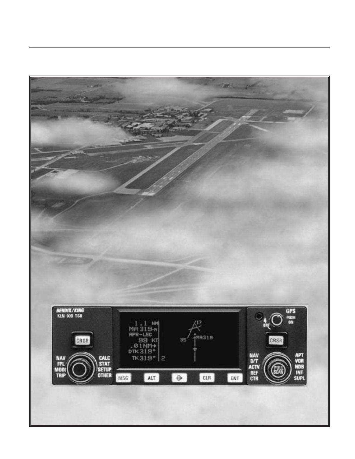
1. Push the power/brightness knob located in the
upper right corner of the unit to the “in” position.
2. After a few seconds of warm up, the screen will
show a Turn-On page with the words SELF TEST
IN PROGRESS at the bottom of the page. Rotate
the power/brightness knob to select the desired
screen brightness. After a few seconds the TurnOn page will automatically be replaced with the
Self Test page. (Note: If the KLN 90B is being
used in the take-home mode, a Take-Home
Warning page is displayed before the Self Test
page and must be acknowledged by pressing
E.) The Self Test page is recognizable because
it shows the date and time on the right side. If the
date and time are incorrect by more than 10 minutes, refer to section 3.2 of this manual. The bottom left side of the Self Test page must display
ANNUN ON to indicate that the KLN 90B has
passed an internal self test.
In most KLN 90B installations the first two characters of the altimeter setting BARO field will be
highlighted in inverse video (dark characters on a
light background) on the right side of the screen.
This area of inverse video is called the cursor.
Use the right inner knob to select the correct first
two characters of the altimeter setting. Next, turn
the right outer knob one step clockwise to position
the cursor over the third character of the altimeter
setting. Use the right inner knob to select the correct number. Once again turn the right outer knob
one step clockwise to position the cursor over the
last character of the altimeter setting. Use the
right inner knob to complete entering the correct
altimeter setting.
Turn the right outer knob clockwise to position the
cursor over the word APPROVE? if the cursor is
not there already. Press E to approve the Self
Test page. (Note: If the KLN 90B is installed for
VFR only operation, a VFR only warning page is
diplayed after the self test page has been
approved. This warning page must be acknowledged by pressing E .)
3. A Database page is now displayed showing the
date the data base expires or the date it expired.
Press E to acknowledge the information displayed on this page.
4. A page displaying the letters PRESENT POS at
the top will now be on the left side of the screen.
In a couple minutes or less, this page will display
the aircraft’s present position. It shows the position both in latitude/longitude and in terms of the
radial and distance from a nearby VOR. Verify
that the position is correct before proceeding.
5. Press the D button. A page with the words
DIRECT TO is now displayed on the left.
In step 6 you will enter the ICAO identifier of the
destination airport. The identifier will have a “K”
prefix for a Continental U.S. airport, a “C” prefix
for a Canadian airport, or a “P” prefix (in many
cases) for an Alaskan airport if the identifier is all
letters. For example, LAX becomes KLAX. For
these countries if the identifier contains any numbers, there is no prefix. For example, TX04 is
entered TX04. For other areas of the world the
airport identifier entered should be identical to
how it is charted.
6. Rotate the left inner knob until the first character
of the airport identifier is displayed. Turn the left
outer knob one step clockwise to move the flashing segment to the second character position.
Rotate the left inner knob to select the second
character of the identifier. Use this procedure to
enter the complete airport identifier.
7. Press E. The right side will display a page
showing the identifier, name and position of the
airport just entered. Confirm that the correct airport is displayed. Press E a second time to
approve the airport data.
8. A Navigation page is now on the right side of the
screen. It displays the distance, ETE, and bearing
to the destination airport. In addition, it displays
groundspeed and a course deviation indicator. If
the left inner knob is rotated one step counterclockwise, you will get an enlarged Navigation
page occupying the entire screen.
Rev 1
PREVIEW OF OPERATION
Page 11
1-1
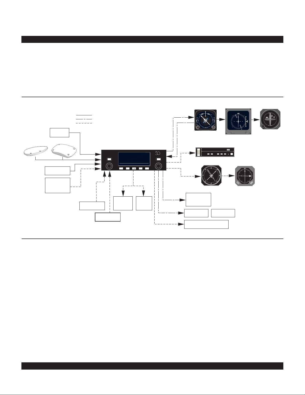
A basic KLN 90B system consists of a panel mounted
KLN 90B GPS sensor/navigation computer, a data base
cartridge, and an antenna. An altitude input is required to
obtain full navigation and operational capabilities.
Additional system components may be added or interfaced to the KLN 90B which increase its features and
capabilities. Some of these optional components include
an external course deviation indicator (CDI) or HSI, RMI,
fuel management system, air data system, ARTEX ELS10 emergency locator transmitter (ELT), autopilot, and
external annunciators.
Rev 1
CHAPTER 1 - KLN 90B SYSTEM COMPONENTS
The KLN 90B panel mounted unit contains the GPS sensor, the navigation computer, a CRT display, and all controls required to operate the unit. It also houses the data
base cartridge which plugs directly into the back of the
unit.
The database cartridge is an electronic memory containing a vast amount of information on airports, navaids,
intersections, special use airspace, and other items of
value to the pilot. The database is designed to be easily
updated by the user by using a laptop computer and
AlliedSignal furnished 3.5 inch diskettes. The database
may also be updated by removing the obsolete cartridge
and replacing it with a current one.
AIRCRAFT
POWER
11/33V
KA 92 OR KA 91 ANTENNA
ALTITUDE
COMPATIBLE
FUEL
MANAGEMENT
SYSTEM
HEADING
AIR DATA
MOVING
MAP
DISPLAYS
ARTEX
ELS-10
ELT
ARINC 429 or
RS 232 INPUT
ALTITUDE ALERT AUDIO
WPT ALERT
MESSAGE
REMOTE ANNUNCIATORS
HSI
EHSI
CDI
OR OR
AUTOPILOT
RMI
OR
CRSR
MSG
D
CLR ENT
KLN 90B TSO
GPS
ı
CRSR
PUSH
ON
BRT
APT
VOR
NDB
INT
SUPL
NAV
D/T
ACTV
REF
CTR
CALC
STAT
SETUP
OTHER
NAV
FPL
MODE
TRIP
PULL
SCAN
$=KOSH |=KOSH
+++++Ê+++++|WITTMAN
DIS 683nm|
GS 193kt|
ETE 3:34|N 43^59.06'
BRG 303^|W 88^33.42'
NAV 1|enr-leg |APT 1
ALT
N
GS GS
33
30
W
24
21
S
15
12
E
6
3
ı
NAV HDG
N
S
E
W
TO
FR
33
30
24
21
15
12
6
3
OBS
GS
N
A
V
ı
ı
N
S
E
W
33
30
24
21
15
12
6
3
A
D
F
N
33
30
W
24
21
S
15
12
E
6
3
A
D
F
A
D
F
NAV NAV
B
ALT HDG NAV APR APGS
ALT HDG NAV APR BC
AP
ENG
TEST
KAP 150
YD
RN RC PC
BC
TRIM
ı
DN
UP
ı
M
L
S
1
AZ
359
12.6
NM
N
33
30
W
24
21
S
15
12
E
6
3
ADF 2
11.5
G
S
KI 525A
EHI 40/50
KI 206
KI 229
KNI 582
RS 232
OUTPUT
RS 232
INPUT
GRAY CODE
KLN 90B SYSTEM
GPS APR GPS CRS
REMOTE SWITCH/
ANNUNCIATORS
SELECTED
COURSE
ARINC 429 or
RS 232 INPUT
REQUIRED FOR ALL INSTALLATIONS
REQUIRED FOR ALL IFR APPROACH INSTALLATIONS
OPTIONAL
LEFT/RIGHT
D-BAR
Page 12

1-2
Two GPS antennas can be used with the KLN 90B. One
is the KA91 and the other is the KA 92. The KA 92 is
used with new production KLN 90Bs and the KA 91 is
used with units that have been upgraded from either a
KLN 90 or a KLN 90A. They are “patch” antennas
designed to always be mounted on the top of the aircraft.
The KLN 90B has analog outputs to drive the left-right
deviation bar of most mechanical CDIs and HSIs. In
addition, it has digital outputs to automatically drive the
course pointer and display flight plan waypoints on the
Bendix/King EHI 40 and EHI 50 electronic HSIs.
The Bendix/King KI 229 and KNI 582 RMIs may be interfaced to the KLN 90B to provide a display of magnetic
bearing to the waypoint.
The NAV mode of the Bendix/King KFC 150, KAP 150,
KAP 150H, KAP 100, KFC 200, KAP 200, KFC 250, KFC
275, KFC 300, KFC 325, KFC 400 and KFC 500 Flight
Control Systems may be coupled to the KLN 90B. Many
other autopilots may also be coupled to the KLN 90B.
Actual autopilot performance and capability when coupled
to the KLN 90B may vary significantly from one autopilot
model to another.
Certain Digiflo™ and Miniflo™ fuel management systems
manufactured by Shadin Co. Inc. as well as certain fuel
computers manufactured by ARNAV Systems, Inc. and
SHELTECH LTD interface with the KLN 90B. These
interfaces allow the pilot to view fuel related parameters
calculated by the KLN 90B such as how much fuel will be
remaining when the aircraft lands at the destination. With
certain Shadin fuel management systems it is possible to
update the fuel on board through the KLN 90B. In these
cases a separate panel mounted interface to the fuel
management computer is not required.
Compatible air data systems are available from
Bendix/King and Shadin Co. An air data system is capable of providing the KLN 90B with true air speed data
which is used for wind determination. The Shadin air
data system also will convert heading data from the
Bendix/King KCS 55A and some other compass systems
to a format that allows wind calculations to be fully automatic.
Altitude may be provided to the KLN 90B from an encoding altimeter, blind encoder, or one of the air data computers mentioned above. Altitude is used as an aid in
position determination when not enough satellites are in
view. Altitude is also used in several altitude related features such as three dimensional special use airspace
alerting, height above airport, and altitude alerting.
Some installations may require remote annunciators to be
mounted in the aircraft panel in order to indicate the status of certain KLN 90B functions. Specifically, the KLN
90B has outputs to provide annunciation for waypoint
alert and message.
In installations where the KLN 90B will be used for
approaches, the installations are more complicated.
External switches and annunciators are required to
change approach modes as well as how the KLN 90B
defines the course to the active waypoint. Selected
course is generally required to be provided to the KLN
90B through an HSI, CDI or EFIS.
Rev 1
KA 91 GPS Antenna KA 92 GPS Antenna
Page 13

CHAPTER 2 - DATABASE
One reason the KLN 90B is such a powerful navigation
system is because of its extensive database. A database
is an area of electronic memory used to store a large catalog of navigational and aeronautical information.
2.1 FUNCTIONS OF THE DATABASE
The database provides two primary functions. First, it
makes pilot interface with the GPS sensor much easier.
Rather than having to manually look up and then enter
the latitude and longitude for a specific waypoint, it allows
you to merely enter a simple waypoint identifier. The
database automatically looks up and displays the latitude
and longitude associated with the identifier. It’s obvious
that the database saves a lot of tedious latitude/longitude
entry and also greatly reduces the potential for data input
mistakes.
The second function of the database is that it serves as a
very convenient means to store and easily access a vast
amount of aeronautical information. Want to know the
tower frequency or the length of the runways at a specific
airport? No need to look them up in a book - just turn a
couple knobs and display the information right on the KLN
90B.
75°
60°
CANADA
EUROPE
2.2 DATABASE COVERAGE AREAS AND CONTENTS
The International Civil Aviation Organization (ICAO) and
Aeronautical Radio, Inc. (ARINC) break the world into the
ten geographic regions shown in figure 2-1. The databases for the KLN 90B have a primary and a secondary
coverage area. The primary coverage areas are indicated
in figure 2-1 and contain more detailed information. The
secondary area contains less detailed information for the
rest of the world.
Specifically, all databases contain complete information
for all worldwide VORs, NDBs, and minimum safe altitudes (MSAs). For its primary area, the database contains public use and military airports which have any runway at least 1000 feet in length. For its secondary area,
the database also contains airports having a hard surface
runway at least 3000 feet in length. Airport communication frequencies and runway information are provided
75°
EAST EUR
60°
45°
30°
15°
0°
15°
30°
45°
60°
PACIFIC
SOUTH PAC
165°150°135°120°105°90°75°60°45°30°15°0°15°30°45°60°75°90°105°120°135°150°165°180°
Americas Database primary area
USA
LATIN AM
SOUTH AM
MID EAST
AFRICA
SOUTH PAC
International Database primary area
PACIFIC
Figure 2-1. KLN 90B Database Geographical Regions
2-1
45°
30°
15°
0°
15°
30°
45°
60°
Rev 1
Page 14

2-2
Rev 1
only for airports in the primary area of the database.
Intersections, air route traffic control center data, flight
service station frequencies, and special use airspace are
also provided only for the primary area.
The following is a list of the KLN 90B database contents:
*AIRPORTS
• Identifier
• Name
• City, State or Country
• Type (public or military)
• Latitude and Longitude
• Elevation
• Approach indicator for precision, non-precision or no
instrument approach at airport
• Radar approach/departure environment indicator
• Whether airport underlies CL B, TRSA, CL C, CTA, or
TMA
• Time relative to UTC (Zulu)
• Communication frequencies (VHF and HF):
ATIS
Clearance delivery
Tower
Ground control
Unicom
Multicom
Approach (IFR)
Departure (IFR)
Class B, Class C, TRSA, CTA, TMA (VFR)
Center (when used for approach)
Arrival
Radar
Director
Radio
AWOS (automatic weather observing station)
AAS (aeronautical advisory service)
ATF (Aerodrome traffic frequency)
CTAF (common traffic advisory frequency)
MF (mandatory frequency)
Ramp control
PCL (pilot-controlled lights)
• Runway data (designation, length, surface, lighting,
traffic pattern direction)
• Airport Services (fuel, oxygen, customs, indicator for
presence of a landing fee)
• Airport Comments (user may manually enter remarks
of up to 33 characters at any 100 airports in database)
VORs
• Identifier
• Name
• Frequency
• DME indicator
• Class (high altitude, low altitude, terminal, undefined)
• Latitude and Longitude
• Magnetic variation
NDBs
• Identifier
• Name
• Frequency
• Latitude and Longitude
(Note - Outer Compass Locators are stored as
Intersections)
*INTERSECTIONS (low altitude, high altitude, SID/STAR,
approach, and outer markers)
• Identifier
• Latitude and Longitude
*SID/STAR/Approach Procedures
• All compatible pilot-nav SID/STAR procedures
• Non-precision approaches (except localizer, LDA
(Localizer Directional Aid), SDF (Simplified Directional
Facility)) approved for overlay use. Includes all public
GPS only approaches.
MISCELLANEOUS
• *Air Route Traffic Control Center (ARTCCs and FIRs)
boundaries and frequencies (VHF and HF)
• *Flight Service Stations (Location of points of
communication and associated frequencies - VHF
and HF)
• Minimum Safe Altitudes
• *Special Use Airspace boundaries (Prohibited,
Restricted, Warning, Alert, MOA, Class B, TRSA,
Class C, CTA, TMA)
250 USER DEFINED WAYPOINTS
• Identifier
• Latitude and Longitude
• Additional data depending on how user defines
waypoint:
User airports (elevation and surface of longest
runway)
User VOR (frequency and magnetic variation)
User NDB (frequency)
And you think your telephone directory has a lot of
information!
* Items indicated with asterisk are included in the primary
database coverage area, but not in secondary coverage
area. The exception is that airports in primary coverage
area include those public and military bases having a runway at least 1000 feet in length. Airports in secondary
coverage area are those having a hard surface runway at
least 3000 feet in length.
Page 15

2.3 USE OF ICAO IDENTIFIERS
2.4 UPDATING THE DATABASE
Waypoints are stored in the KLN 90B database almost
exclusively by their ICAO identifiers. ICAO is an internationally accepted reference for the data. In almost all
cases the proper ICAO identifiers may be taken directly
from Jeppesen Sanderson or government aeronautical
charts. For example, Dallas and Los Angeles VORs have
the familiar ICAO identifiers DFW and LAX, respectively.
Please note that one area of potential confusion is airport
identifiers in the Continental United States, Alaska, and
Canada. Many airport identifiers in the database have
four letters beginning with a prefix letter that corresponds
to the geographic area in which it is located. The prefix
letter for the Continental United States is “K”. Thus, the
identifier for Dallas/Fort Worth International airport is
KDFW, not DFW. This distinguishes the airport identifier
from the VOR identifier. Likewise, the identifier for Los
Angeles International airport is KLAX while the VOR identifier is LAX. The prefix letter for Alaska is “P” and for
Canada is “C”.
NOTE: There are several exceptions in Alaska. In many
cases, airports with three letter identifiers receive the
prefix “P”, but there are many that don’t. The most reliable
method of determining an Alaska airport identifier is to
look it up from the airport name or city. See section 3.7.4,
“Selecting Waypoints by Name or CIty”.
Not all airport identifiers receive the prefix letter. Airport
identifiers which are combinations of letters and numbers
do not receive the prefix letter. Examples of airport identifiers not using the prefix are 3C2, 7TX6, and M33.
So remember, if you are entering or looking for an
airport identifier that is all letters (no numbers) then it
will begin with a “K” prefix in the Continental U.S., a
“P” in Alaska, or a “C” in Canada. If there are numbers in the identifier then a prefix is not used. For
other areas of the world the airport identifier stored in
the KLN 90B database is identical to how it is
charted.
The information stored in the database would eventually
become obsolete if there wasn’t some means to update it.
For example, navaids can move or change frequency,
new runways can be added to an airport, communication
frequencies can change, and on and on.
The database is housed in a cartridge which plugs
directly into the back of the KLN 90B. It is designed so
that there are two ways for the user to easily keep the
database current. The first is to electronically update the
database by means of 3.5” diskettes supplied by
AlliedSignal and a laptop computer. This method does
not involve removing the KLN 90B from the aircraft’s
instrument panel. A jack, usually mounted in the aircraft’s
instrument panel, provides a means of interfacing the
KLN 90B with the computer via an interface cable. The
diskettes are not returned to AlliedSignal.
The second method of database update is to remove the
old cartridge and insert a current cartridge. This method
involves returning the old cartridge to AlliedSignal.
Every 28 days, AlliedSignal receives new NavData™
information from Jeppesen Sanderson. This information
is processed and downloaded onto both diskettes and
database cartridges. AlliedSignal makes these two types
of update services available to you in a choice of several
subscription or random update programs. See section 2.7
of this manual for details on these programs.
Regardless of whether the computer method or the cartridge exchange method of database updating is used,
AlliedSignal sends the update so that it arrives prior to the
next effective date. The new update may be installed any
time prior to the effective date and the KLN 90B will use
the previous data up to the effective date and automatically begin using the new data on the effective date.
In order to get maximum utilization from the KLN 90B,
AlliedSignal highly encourages you to update the database on a frequent basis, if not every 28 days. It is also a
matter of safety to not fly with out of date information.
WARNING: The accuracy of the database information is only assured if it is used before the end of the
effectivity period. Use of out of date database information is done entirely at the user’s own risk.
2-3
Rev 1
Page 16

2-4
Rev 1
2.4.1 Computer Updating Of The Database
Update information is sent to you on several 3.5” disks.
In order to use this update method you must have access
to an IBM compatible computer having a disk drive capable of using and booting (loading) from 3.5” 1.44
megabyte high density disks. This computer also needs
to have an available COM 1 or COM 2 serial port. In
addition, an optional PC Interface kit must be used.
Included in the kit are a data loader jack (wired to the
KLN 90B and usually installed in the aircraft’s instrument
panel) and an interface cable that plugs into both the
computer and into the data loader jack.
CAUTION: The database must be updated only while
the aircraft is on the ground. The KLN 90B does not
perform any navigation functions while the database
is being updated. Since a database update takes
approximately 10 minutes it is a good idea to turn off
all electrical equipment on the aircraft except for the
KLN 90B to avoid running down the aircraft battery.
NOTE: The disks sent to you can only be used to update
one KLN 90B, although they can update this specific unit
numerous times. The first time the disks are used in an
update operation, a unique identification code from the
KLN 90B being used is uploaded to the disks. These
disks may be used in this specific KLN 90B an unlimited
number of times which could be required if you switch
back and forth between the North American and
International data bases during one update cycle. These
disks may not, however, be used to update other KLN
90Bs. This update protection ensures that Jeppesen
Sanderson is properly compensated for the use of their
NavData™.
Follow these steps to update the KLN 90B:
1. Plug the 9 pin female connector end of the interface
cable into a COM serial port of the computer. If the computer has COM 1 and COM 2 serial ports, either may be
used. Some computers use a 9 pin COM serial port connector while other computers use a 25 pin connector. If
the computer being used has a 9 pin connector, the interface cable connector will plug directly into the computer’s
9 pin connector. If the computer’s COM serial port uses a
25 pin connector, use the 25 pin to 9 pin adapter included
in the PC interface kit to adapt the interface cable’s connector to the computer’s connector.
2. Plug the other end of the interface cable (4 conductor
male plug) into the data loader jack that is mounted in the
aircraft.
Page 17

2-5
Rev 1
3. Turn on the computer being used for the database
update. Insert Disk 1 into the computer’s disk drive.
There can be either 2 or 3 disks used for the update so
be sure the label on the outside of the disk says “Disk 1 of
2” or “Disk 1 of 3”. The program on the disk will automatically “boot” (load) and the computer screen will display
“Ready” when the computer is ready to continue with the
database update operation.
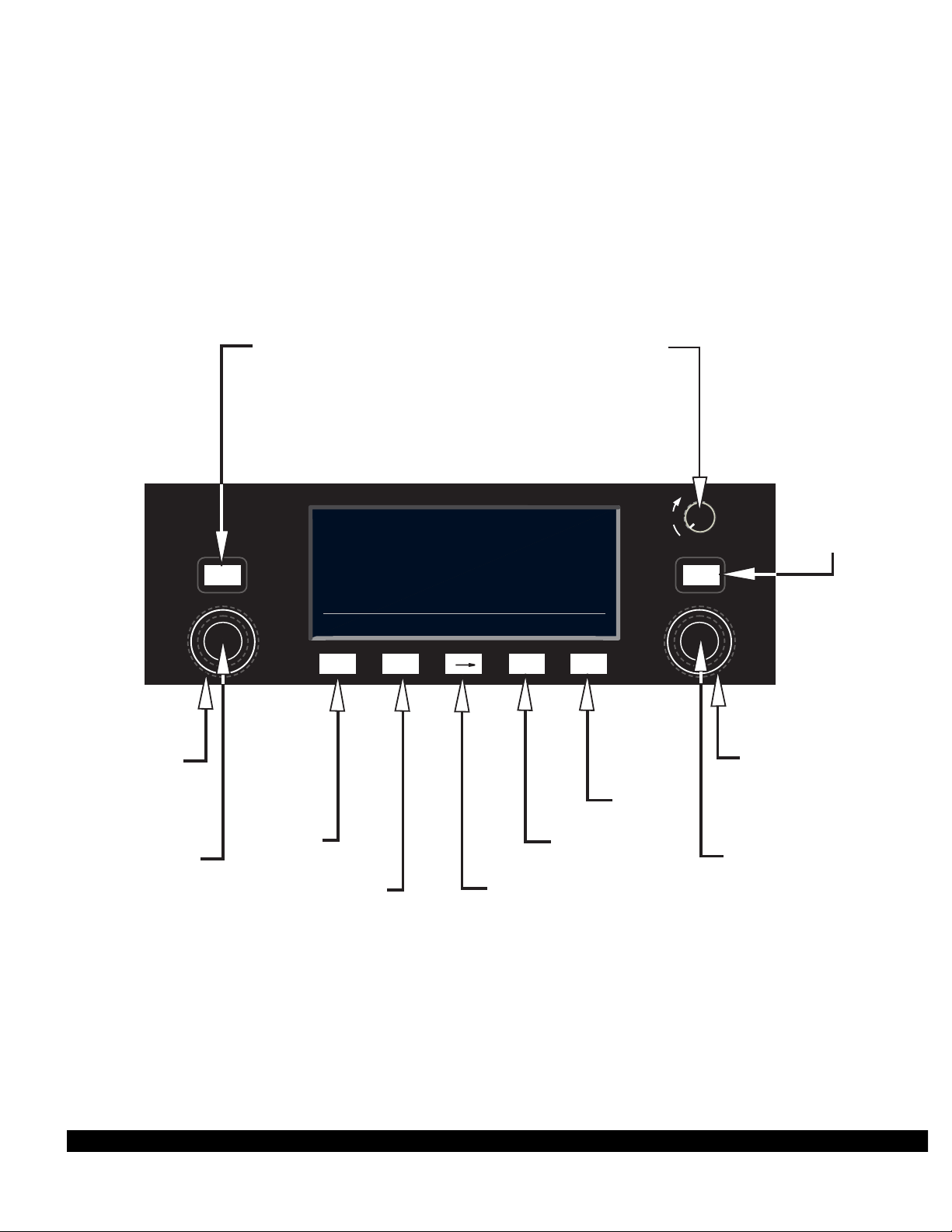
4. Turn on the KLN 90B. Press E as required to
approve the Self Test and Database pages. Use the left
outer knob to select the Setup (SET) type pages and the
left inner knob to select the SET 0 page (figure 2-2).
5. Press the left C. UPDATE PUBLISHED DB will
now be displayed as in figure 2-3.
6. Press E. The database region and the expiration
date of the database presently loaded in the KLN 90B is
displayed (figure 2-4). If the database is out of date the
word EXPIRES changes to EXPIRED.
7. Press E to acknowledge the information on this
page and to continue the update procedure. The estimated load time in minutes is now displayed (figure 2-5).
NOTE: In steps 5, 6, and 7, repeated presses of @will
terminate the update process and bring the display back
to the original SET 0 page shown in figure 2-2.
U P D A T E
D A T A B A S E
O N G R O U N D
O N L Y
SET 0
U P D A T E
D A T A B A S E
UPDATE PUBLISHED DB
CRSR ent
U P D A T E
N AMERICAN
DATA BASE EXPIRES
17 AUG 94
U P D A T E ?
CRSR ent
U P D A T E
D A T A B A S E
E S T . L O A D
T I M E : 10 MIN
A P P R O V E ?
CRSR ent
Figure 2-2
Figure 2-3
Figure 2-4
Figure 2-5
Page 18

2-6
Rev 1
8. Press E to acknowledge the estimated load time
and begin erasing the existing database. The unit will
now display ERASING DATA BASE (figure 2-6). After
the database has been erased, loading of the new data
begins automatically. As the new data is being loaded,
the percentage of transfer is displayed (figure 2-7).
9. Monitor the computer screen. When the first disk is
complete the computer screen will display “Insert Disk 2
then press any key to continue.” Disk 1 should now be
removed from the disk drive and disk 2 should be
inserted. Press any key on the computer. The load operation will continue. If there are 3 disks the computer
screen will prompt when to use disk 3.
10. The KLN 90B will indicate when the database update
is complete as shown in figure 2-8. The computer screen
will display the new database expiration date. You may
either turn the KLN 90B off at this point or press E to
restart the KLN 90B.
11. Remove the interface cable. Remove the disk from
the computer. Turn off the computer.
The chances are small of having difficulty updating the
database but if you have a problem:
First check that the interface cable is properly connected
and that the computer is turned on. If there is a problem
with the connection or the computer the KLN 90B will display LOADER NOT READY. When the problem is cor-
rected this prompt is removed and the update operation
can continue from where it left off.
If the wrong disk is inserted the computer screen will display “Incorrect Disk - please insert disk __.”, where the
number 2 or 3 is inserted in the blank.
If an internal test fails after the data has been loaded, the
KLN 90B will display CHECKSUM ERROR, DATA BASE
INVALID, ACKNOWLEDGE?. Press E to acknowl-
edge. The KLN 90B will then display RETRY and EXIT.
Use the left outer knob to position the cursor over the
desired choice and press E.
There are other error messages that may be displayed. If
you have a problem that you can’t resolve, write down
any error messages to aid your Bendix/King Service
Center in identifying the problem.
U P D A T E
D A T A B A S E
E R A S I N G
D A T A B A S E
SET 0
Figure 2-6
U P D A T E
D A T A B A S E
14 PERCENT COMPLETE
SET 0
Figure 2-7
U P D A T E
D A T A B A S E
UPDATE PUBLISHED DB
COMPLETED
ACKNOWLEDGE?
CRSR ent
Figure 2-8
Page 19
2-7
Rev 1
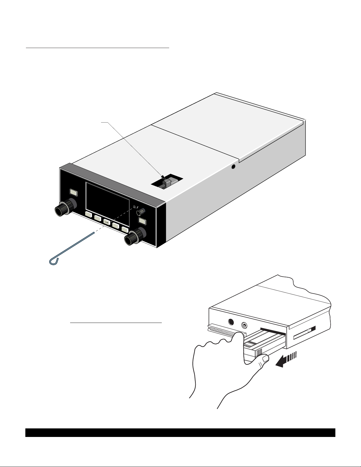
1. Insert the KLN 90B insertion/removal tool (supplied
with unit) in the small hole located on the right side of the
front of the unit (figure 2-9). A standard 3/32 inch Allen
wrench may also be used.
2. Turn the tool counterclockwise until the locking mechanism becomes loose and then continue turning counterclockwise until it just barely begins to become snug. Do
not turn so far counterclockwise that the mechanism
starts to bind and can no longer be turned.
3. The KLN 90B should now be loose from the rack.
Pull the unit out of the rack by pulling on the sides of the
radio’s front panel. DO NOT REMOVE BY PULLING ON
THE KNOBS.
4. Remove the old database cartridge by pulling it
straight out the back of the KLN 90B (figure 2-10).
5. Remove the new database cartridge from its shipping
container. Note that the label on the cartridge indicates
PUSH
ON
APT
VOR
NDB
INT
SUPL
ı
MSG
CLR
ENT
D
BRT
NAV
D/T
ACTV
REF
CTP.
KLN 90B TSO
GPS
FRONT LUG UP
AND BACK LUG DOWN
CALC
STAT
SETUP
OTHER
NAV
FPL
MODE
TRIP
CRSR
CRSR
PULL
SCAN
ALT
Figure 2-9
2.4.2 Cartridge Exchange Updating of the Database
To exchange the KLN 90B cartridge it is necessary to
remove the KLN 90B from the aircraft’s instrument panel.
The KLN 90B and the mounting rack have been designed
to provide for easy removal. Follow these steps to update
the database cartridge.
INSERT TO HERE
North American
P/N: 071-1469-00
AIRAC No. 8811
Document: 723-8088-11
Figure 2-10
Page 20
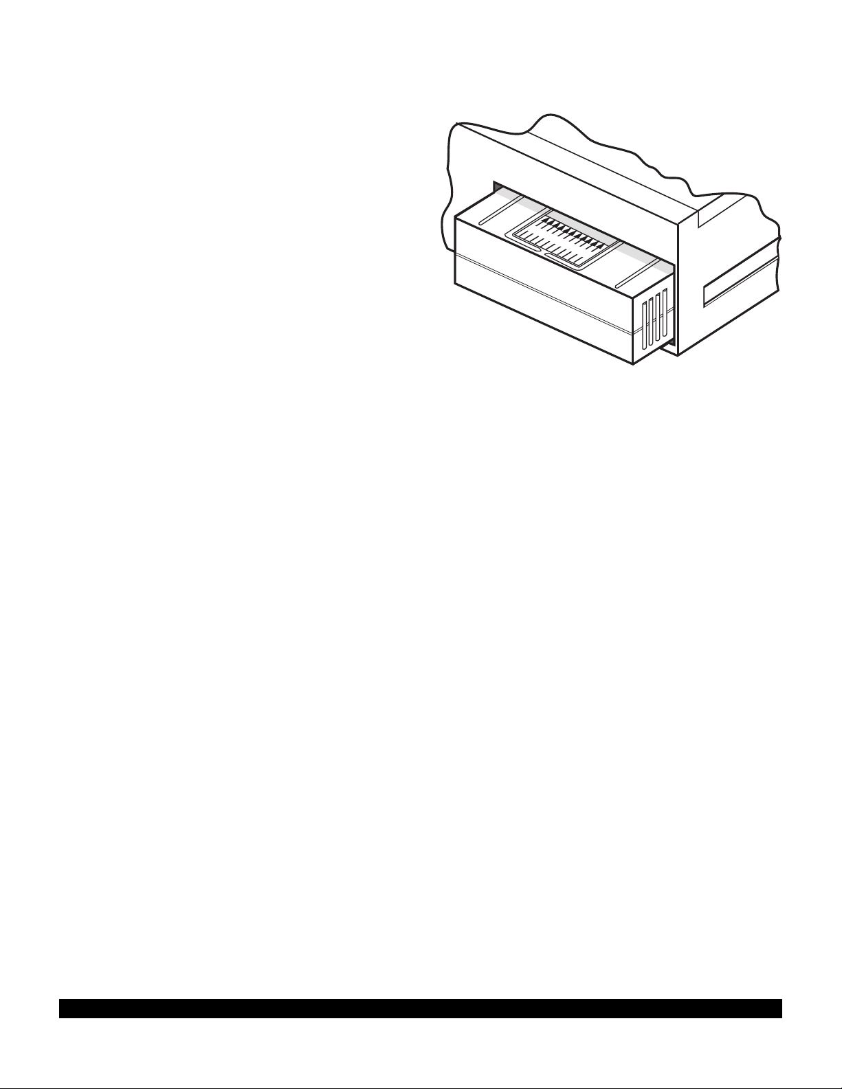
which side is up and which end to insert into the KLN
INSERT TO HERE
90B. Insert the new cartridge into the back of the unit.
When the cartridge is properly inserted, the “Insert To
Here” marking on the label can just be seen protruding
from the rear of the KLN 90B (figure 2-11).
6.Make sure that the front lug of the locking mechanism
is in the up position (figure 2-9). Insert the KLN 90B
back in the rack as far as it will go.
7.Re-insert the insertion/removal tool. Turn the tool
clockwise until snug. The KLN 90B should now be locked
back into the mounting rack. Pull gently on the front
panel to verify that the unit is indeed locked into its rack.
8.The container which was used to ship the new cartridge to you is used to return the old cartridge back to
AlliedSignal. A return shipping label is included in the
container. Remove the backing from the label and place
it in the address position of the shipping container.
9.Insert the old cartridge into the container. Peel off the
protective backing from the adhesive on the end flap of
the container. Press the flap against the adhesive to seal
the container.
10.Please return the old cartridge promptly by mailing
immediately at any mailbox. No postage is required if
mailed from within the U.S. Users will be billed for cartridges not returned and no additional cartridges will be
sent until either the old cartridge or payment for the old
cartridge is received.
North American
P/N: 071-1469-00
AIRAC No. 8811
Document: 723-8088-11
Figure 2-11
2.7 DATABASE UPDATE SERVICE OPTIONS
The following tear-out pages can be used for ordering the
North American and International database update services from AlliedSignal. The forms may be mailed or
faxed for your convenience.
2.5 USER DEFINED DATABASE
In addition to the published database of airports, VORs,
NDBs, and intersections stored in the cartridge, you may
create up to 250 other waypoints. These waypoints may
be designated by you to be one of the four waypoint types
above or as a waypoint not falling into one of these types.
In the latter case the waypoint is called a Supplemental
waypoint. Section 5.4 describes how you may create a
user-defined waypoint.
2.6 INTERNAL MEMORY BACKUP BATTERY
The KLN 90B contains an internal lithium battery that is
used to “keep-alive” the user-defined database as well as
flight plans. This battery has a typical life of three to five
years.
replaced every three years at an authorized Bendix/King
Service Center.
It is highly recommended that the battery be
2-8
Rev 1
Page 21

Name:
Company:
Address:
City:
State: Zip Code:
Country:
Telephone: ( )
FAX: ( )
Aircraft Make:
Aircraft Model: ______
Please set up the service under:
MasterCard/VISA
Method of Payment
Check/Money order enclosed
Wire Transfer:
Chase Manhattan Bank, NY
Acct #910-2-538734
Tax may apply in some states.
See pricing sheet.
Number
Expires
Signature
AlliedSignal GAA offers several update service options to suit your requirements.
Please select the service desired, then fill
out and mail this order form. Credit card
orders may be faxed.
Updates from the Internet can be obtained
directly by logging onto the AlliedSignal
Internet site and following the instructions
provided, or by calling the telephone number below to set up an account.
Note: Updates are current for 28 days
after effective date on diskette. If you
select any service other than the complete
13-time service, your KLN 90B will begin
alerting you after 28 days that your data
base is out of date.
Send to:
AlliedSignal CAS
Data Base Update Service
Mail Drop #66
400 N. Rogers Road
Olathe KS 66062-1212
Telephone: (913) 768-3020
FAX: (913) 768-3904
Check One:
Complete Update Service.
Provides 13 updates–one every 28
days for one year.
Six-time Update Service.
Provides six updates–one every 56
days for one year.
Four-time Update Service.
Provides four updates–one during
each quarter for one year.
Single Update. Provides one
update upon receipt of order.
Check Requested Data Base:
Americas Data Base
International Data Base
Check One:
Database Card Format
(available in U.S./Canada only)
Diskette Format
(Laptop Computer Required. See
section 2 of KLN 90B Pilot’s Guide
for details.)
KLN 90B Data Base Update Service Order Form
Consult Pricing Sheet (006-08794-0001) for Service Prices
A
Page 22
BUSINESS REPLY MAIL
FIRST-CLASS MAIL PERMIT NO. 121 OLATHE, KANSAS
POSTAGE WILLBE PAID BY ADDRESSEE
Fold here
NO POSTAGE
NECESSARY
IF MAILED
IN THE
UNITED STATES
ALLIEDSIGNAL COMMERCIAL AVIONICS SYSTEMS
M D 66
400 NORTH ROGERS ROAD
OLATHE KS 66062-9987
Tape here
Page 23

CHAPTER 3 - LEVEL 1 OPERATION
This is the first of three chapters specifically dealing with
operating the KLN 90B. In this chapter you will learn the
basic operation of the front panel controls and then how
3.1 COVERAGE AREA
The KLN 90B was designed to provide worldwide navigation coverage from North 74°latitude to South 60°latitude
(figure 3-1). Outside this area, magnetic variation must
74°
60°
45°
30°
to perform Direct To navigation (navigating from your present position direct to your desired location).
be manually entered as discussed in section 5.12. See
section 2.2 for the database coverage areas.
74°
60°
45°
30°
15°
0°
15°
30°
45°
60°
Figure 3-1 KLN 90B Navigation Coverage Area
IMPORTANT:
Special installation procedures must be followed in order for the KLN 90B to be certified for IFR use.
Consult the KLN 90B Flight Manual Supplement for the operating limitations of this unit.
15°
0°
15°
30°
45°
60°
3-1
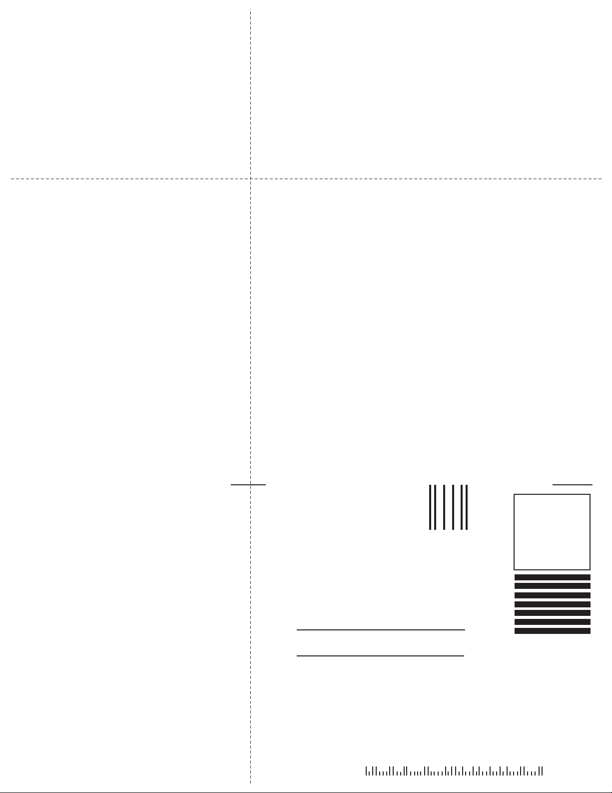
Rev 1
Page 24
CRSR
MSG
D
CLR ENT
KLN 90B TSO
GPS
ı
CRSR
PUSH
ON
BRT
APT
VOR
NDB
INT
SUPL
NAV
D/T
ACTV
REF
CTR
CALC
STAT
SETUP
OTHER
NAV
FPL
MODE
TRIP
PULL
SCAN
LEFT OUTER
MESSAGE
DIRECT TO
CLEAR
ENTER
RIGHT
OUTER
LEFT INNER
RIGHT
INNER
LEFT CURSOR POWER/BRIGHTNESS
RIGHT
CURSOR
$=KOSH |=KOSH
+++++Ê+++++|WITTMAN
DIS 683nm|
GS 193kt|
ETE 3:34|N 43^59.06'
BRG 303^|W 88^33.42'
NAV 1|enr-leg |APT 1
ALT
ALTITUDE
KLN 90B CONTROLS
Figure 3-2
Page 25

3.2 TURN-ON AND SELF TEST
Enough of the preliminaries. Let’s get started into actually turning the KLN 90B on and using it! Figure 3-2 will
fold out and allow you to use it as a reference as you read
this chapter, especially if you don’t have a KLN 90B
immediately at hand. The steps below take a lot of words
to explain, but you will find that in actual use you will
accomplish these steps in just a few moments.
NOTE: When power is applied to the KLN 90B it always
“wakes up” in the Enroute-Leg mode. Only the EnrouteLeg mode is described in this chapter. In this mode the
KLN 90B performs great circle navigation (the shortest
distance between two points located on the earth’s surface). The course deviation output displayed on the unit’s
internal course deviation indicator (CDI) and provided to
an external HSI or CDI is five nautical miles left and right,
full scale sensitivity. The other modes of the unit are
described in section 5.9 and in chapter 6.
1.Turn-on the KLN 90B by pressing the power/brightness knob to the “in” position. The power/brightness
knob is located on the upper right side of the unit. It
takes just a few seconds for the screen to warm up.
2.The Turn-On page will be displayed for a few seconds (figure 3-3). During this time the KLN 90B performs an extensive internal test. The ORS
(Operational Revision Status) level number in the
upper right corner of the display should match the
ORSlevel indicated on the first page of this Pilot’s
Guide (page before Table of Contents). If desired,
you may program four lines of personalized information which is displayed each time the Turn-On page is
in view. The procedure for doing this is described in
section 5.7.
When the internal test is complete, the Turn-On page
will automatically be replaced by the Self Test page
(figure 3-4). Note: if the KLN 90B is operating in the
take-home mode, the Take-Home Warning page (figure 3-5) is displayed first and must be acknowledged
by pressing
tion on the Take-Home mode.
E. See section 5.14 for more informa-
GPS ORS 20
c1994 ALLIEDSIGNAL INC
SELF TEST IN PROGRESS
Figure 3-3
DIS 34.5NM|DATE/TIME
+++++j+‚⁄++| 31 JUL 94
OBS IN 242^|08:10:03CST
OUT 315^|ALT 1100ft
RMI 130^|BARO:29.92"
ANNUN ON| APPROVE?
enr-leg CRSR
Figure 3-4
3.Adjust the display brightness to the desired level by
rotating the power/brightness knob. Clockwise rotation increases brightness and counterclockwise rotation decreases brightness.
4.Verify that the data displayed on the left side of the
Self Test page is the same as is being displayed on
the appropriate equipment in the aircraft which is
interfaced to the KLN 90B. If the KLN 90B is not connected to any other equipment in the aircraft, you
may skip to step 5.
WARNING:
SYSTEM IS IN TAKE-
HOME MODE: DO NOT
USE FOR NAVIGATION
ACKNOWLEDGE?
enr-leg ent
Figure 3-5
3-3
4
Rev 1
Page 26

3-4
Rev 1
The distance field (DIS) always displays 34.5 NM
(nautical miles). If the KLN 90B is interfaced to a
compatible indicator that displays DME distance, the
indicator should be displaying 34.5 nautical miles.
If the KLN 90B is interfaced with a mechanical NAV
indicator such as an HSI or a course deviation indicator (CDI), the D-bar (deviation bar) should be indicating a half scale deviation to the right. In some EFIS
installations the D-bar may be deflected one third of
full scale. This is due to the different CDI scale factors
that are used. The TO/FROM indicator should be
showing FROM.
If the KLN 90B is interfaced with a NAV indicator
such that the KLN 90B can "read" the selected
course from the NAV indicator, then the OBS IN field
should display the same course as on the NAV indicator.
The OBS OUT field always displays 315 degrees and
is only applicable when the KLN 90B is interfaced
with an HSI which has a driven course pointer capable of being driven by the KLN 90B. This type of HSI
is normally found in jets and turboprops. If this type
of NAV indicator is interfaced to the KLN 90B, the
course pointer on the NAV indicator should be driven
to 315 degrees and both the OBS IN and OBS OUT
fields should be displaying 315 degrees.
The RMI field always displays 130 degrees. If the
KLN 90B is connected to a compatible RMI in the aircraft, the RMI should indicate a bearing to the station
of 130 degrees.
If any of the above checks fail, do not use the associated equipment with the KLN 90B.
5. If the KLN 90B has passed the internal self test, the
bottom left side of the Self Test page will display
ANNUN ON to indicate that the external annunciators, if installed, should all be illuminated. If instead,
a flashing TEST FAIL is displayed, recycle power to
the KLN 90B. If the Self Test page still displays
TEST FAIL, the KLN 90B requires repair and should
not be used for navigation.
Page 27

3-5
Rev 1
The KLN 90B needs to have the correct time, date,
and position to be able to determine which satellites
should be in view. This information is stored in the
battery backed memory of the KLN 90B so it is not
normally required to update it. If the KLN 90B has the
correct time, date, and position, then the time to first
fix will usually be just a couple of minutes or less. If
this information is not correct, then the KLN 90B will
start to look for any satellites. Eventually, the KLN
90B will find enough satellites to determine the position of the aircraft. This process can take as long as
12 minutes but will normally be around 6 minutes. It is
possible for you to update this information manually
which will allow the KLN 90B to reach a NAV ready
status much faster. To set the time and date follow
steps 6 and 7. If the date and time are correct, or
acquisition time is not important, then skip to step 8.
6. If the date is incorrect, rotate the right outer knob
counterclockwise until the cursor is over the entire
date field (figure 3-6). Rotate the right inner knob
until the correct day of the month is displayed (figure
3-7). Then, rotate the right outer knob one step
clockwise to place the flashing part of the cursor over
the month field (figure 3-8). Rotate the right inner
knob to display the correct month (figure 3-9). Rotate
the right outer knob one step clockwise again and
use the right inner knob to select the first digit of the
correct year (Figure 3-10). Next, rotate the right outer
knob one more step clockwise and then use the right
inner knob to select the second digit of the year
(figure 3-11). When the date is correct, press E.
7. If it is necessary to reset the time, use the right outer
knob to position the cursor over the time zone field
(figure 3-12). Use the right inner knob to select the
desired time zone (figure 3-13). The following are the
time zones which the KLN 90B is capable of
displaying:
UTC Coordinated Universal Time (Zulu)
GST Greenland Standard Time (UTC - 3)
GDT Greenland Daylight Time (UTC - 2)
ATS Atlantic Standard Time (UTC - 4)
ATD Atlantic Daylight Time (UTC - 3)
EST Eastern Standard Time (UTC - 5)
EDT Eastern Daylight Time (UTC - 4)
CST Central Standard Time (UTC - 6)
CDT Central Daylight Time (UTC - 5)
MST Mountain Standard Time (UTC - 7)
MDT Mountain Daylight Time (UTC - 6)
PST Pacific Standard Time (UTC - 8)
PDT Pacific Daylight Time (UTC - 7)
AKS Alaska Standard Time (UTC - 9)
AKD Alaska Daylight Time (UTC - 8)
HAS Hawaii Standard Time (UTC - 10)
HAD Hawaii Daylight Time (UTC - 9)
SST Samoa Standard Time (UTC - 11)
SDT Samoa Daylight Time (UTC - 10)
|DATE/TIME
| 31 JUL 94
|08:10:14CST
|ALT 1100ft
|BARO:29.92"
|
CRSR
|DATE/TIME
| 03 AUG 94
|08:10:14CST
|ALT 1100ft
|BARO:29.92"
| APPROVE?
CRSR
|DATE/TIME
| 03 AUG 94
|14:10:55UTC
|ALT 1100ft
|BARO:29.92"
| APPROVE?
CRSR
|DATE/TIME
| 03 AUG 94
|08:10:14CST
|ALT 1100ft
|BARO:29.92"
| APPROVE?
CRSR
|DATE/TIME
| 03 AUG 9!
|08:10:14CST
|ALT 1100ft
|BARO:29.92"
| APPROVE?
CRSR
|DATE/TIME
| 03 AUG !!
|08:10:14CST
|ALT 1100ft
|BARO:29.92"
| APPROVE?
CRSR
|DATE/TIME
| 03 !!! !!
|08:10:14CST
|ALT 1100ft
|BARO:29.92"
| APPROVE?
CRSR
|DATE/TIME
| 03 !!! !!
|08:10:14CST
|ALT 1100ft
|BARO:29.92"
| APPROVE?
CRSR
Figure 3-6 Figure 3-7
Figure 3-8 Figure 3-9
Figure 3-10 Figure 3-11
Figure 3-12 Figure 3-13
Page 28

3-6
Rev 1
You will be able to change the time zone any time you
desire on several other pages, so don’t worry if you’re not
sure which time zone to choose. UTC - Coordinated
Universal Time (also called “Zulu”) is always a safe
choice.
Once you have selected the desired time zone, turn the
right outer knob one step counterclockwise to position the
cursor over the entire time field (figure 3-14). Use the right
inner knob to select the correct hour (figure 3-15). Since
24 hour time is used, be sure to add 12 if the time is after
1:00 P.M.(2:30 P.M. becomes 14:30). Now turn the right
outer knob one step clockwise to position the flashing part
of the cursor over the first minute’s position (figure 3-16).
Turn the right inner knob to select the desired value.
Turning the right outer knob one more step clockwise positions the flashing part of the cursor over the second
minute’s position, and the right inner knob is now used to
finalize the time selection (figure 3-17). When the correct
time has been entered, press E to start the clock running. Don’t worry that you can’t update the seconds. The
KLN 90B system time will automatically be corrected very
precisely once a satellite is received.
8. Turn the right outer knob clockwise to position the
cursor over the first two digits of the altimeter baro set
field if the cursor is not there already (figure 3-18).
The last KLN 90B baro setting entered is displayed.
If the correct altimeter setting is displayed skip to step
10 after reading the following notes.
NOTE: The KLN 90B will use an altitude input from an
altitude encoder or air data computer. Since the altitude
from these devices is usually pressure altitude, an altimeter baro correction is required to ensure maximum accuracy. This altitude input is used for altitude related features of the KLN 90B. Therefore, it is important to keep
the altimeter baro setting updated on the Self Test page
when power is first applied to the KLN 90B and on the
Altitude page each time a new baro correction is made to
the aircraft’s altimeter.
NOTE: The units of the altimeter baro setting may be
changed at a later time from inches to millibars on the
SET 7 page.
NOTE: The altimeter baro set field will not be a cursor
field if the KLN 90B is interfaced to certain air data/altimeter systems which update the baro set field when the aircraft’s altimeter baro setting is updated.
|DATE/TIME
| 03 AUG 94
|14:10:59UTC
|ALT 1100ft
|BARO:29.92"
| APPROVE?
CRSR
|DATE/TIME
| 03 AUG 94
|16:!!:08UTC
|ALT 1100ft
|BARO:29.92"
| APPROVE?
CRSR
|DATE/TIME
| 03 AUG 94
|16:27:42UTC
|ALT 1100ft
|BARO:29.92"
| APPROVE?
CRSR
|DATE/TIME
| 03 AUG 94
|16:27:08UTC
|ALT 1100ft
|BARO:29.92"
| APPROVE?
CRSR
|DATE/TIME
| 03 AUG 94
|16:!!:08UTC
|ALT 1100ft
|BARO:29.92"
| APPROVE?
CRSR
Figure 3-14
Figure 3-15
Figure 3-16
Figure 3-17
Figure 3-18
Page 29
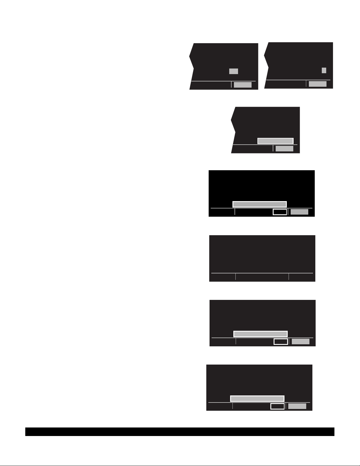
3-7
Rev 1
9. To enter the correct baro setting, rotate the right inner
knob to select the first two digits of the correct altimeter setting (figure 3-19). Rotate the right outer knob
one step clockwise to move the flashing cursor over
the third position. Use the right inner knob to select
the correct number. Use the right outer and inner
knobs to complete the baro setting (figure 3-20).
Now press E.
10. With the correct altimeter setting entered, the altitude
displayed on line 4 should be correct within 100 feet.
11. Turn the right outer knob clockwise to position the
cursor over APPROVE? if it is not there already
(figure 3-21). Press E to approve the Self Test
page. If the KLN 90B altitude alert audio is utilized in
the installation, five beeps should be heard when the
Self Test page is approved. The alert audio volume
may later be adjusted on the SET 9 page. (Note: If
the KLN 90B is installed for VFR only operation, a
VFR only warning page is displayed after the self
test page has been approved (Figure 3-22). This
warning page must be acknowledged by pressing
E .) If the KLN 90B is installed with an external
GPS CRS switch and the switch is in the OBS
position, then the OBS warning page will be
displayed (figure 3-23). The GPS CRS switch
should be pushed so that the LEG mode is
selected.)
12. The Database page will now be displayed with the
cursor over ACKNOWLEDGE?. Line 1 indicates the
coverage area of the database being used. If the
database is current, line 3 will show the date when
the database expires (figure 3-24).
If the database is out of date, line 3 shows the date
that it expired (figure 3-25). The KLN 90B will still
function with an out of date database; however, you
must exercise extreme caution and always verify that
the database information is correct before using information from an out of date database.
Press E to acknowledge the information on the
Database page.
WARNING: The accuracy of the database information
is assured only if the database is current. Operators
using an out of date database do so entirely at their
own risk.
|DATE/TIME
| 03 AUG 94
|16:28:24UTC
|ALT 1200ft
|BARO:30.02"
| APPROVE?
CRSR
|DATE/TIME
| 03 AUG 94
|16:27:53UTC
|ALT 1100ft
|BARO:30.92"
| APPROVE?
CRSR
|DATE/TIME
| 03 AUG 94
|16:28:08UTC
|ALT 1100ft
|BARO:30.02"
| APPROVE?
CRSR
Figure 3-19
Figure 3-20
Figure 3-21
Figure 3-22
Figure 3-25
N AMERICAN
DATA BASE EXPIRED
04 JUL 94
ALL DATA MUST BE
CONFIRMED BEFORE USE
ACKNOWLEDGE?
enr-leg ent CRSR
FOR VFR USE ONLY
ACKNOWLEDGE?
ent CRSR
Figure 3-23
WARNING
SYSTEM IS IN OBS MODE
PRESS GPS CRS BUTTON
TO CHANGE TO LEG MODE
enr:016
Figure 3-24
N AMERICAN
DATA BASE EXPIRES
29 AUG 94
ACKNOWLEDGE?
enr-leg ent CRSR
Page 30

The NAV 2 page (present position) is now automatically
displayed on the left side of the screen and the waypoint
page for the waypoint which was active when the KLN
90B was last turned off will be displayed on the right side
(figure 3-26). If the last active waypoint was an airport,
the APT 4 page (airport communications) will be displayed. Isn’t that convenient! Almost always, the waypoint which was active when you last removed power
from the KLN 90B is the airport where you landed.
Therefore, when you get ready to depart, the airport communication frequencies for that airport will automatically
be displayed for you!
When the NAV 2 page first appears, it is possible that the
present position will be dashed. It can take the KLN 90B
several minutes to acquire the GPS satellites and to
make its initial calculation of your position. When the
KLN 90B reaches a NAV ready status and is able to navigate, the NAV 2 page will display your present position in
two ways (figure 3-27). The bottom of the page will display the aircraft’s latitude and longitude. Above the latitude/longitude position is the present position expressed
as the distance and radial from a nearby VOR. The VOR
displayed on the NAV 2 page is the nearest low or high
altitude class VOR. Terminal class VORs are not used
because many charts do not depict a compass rose
around them and verifying the displayed radial would be
difficult. Verify that the present position shown on the
NAV 2 page is correct.
PRESENT POS|=KHIF
|CLR 124.10
--- ---^fr |GRND 121.60
---- -nm |TWR 126.20
- --^--.--'|APR 121.10
----^--.--'|DEP 121.10
NAV 2 enr-leg APT 4
Figure 3-26
PRESENT POS|
|
OGD 122^fr|
8.2nm|
N 41^07.60'|
W111^58.30'|
NAV 2
Figure 3-27
NOTE: In order to reach a NAV ready status, the aircraft
must be away from obstructions blocking the GPS
antenna’s view of required satellites. If the KLN 90B fails
to reach a NAV ready status within five minutes, refer to
section 3.6, “Initialization and Time To First Fix”.
NOTE: When the KLN 90B is interfaced with certain
Shadin fuel flow computers, the KLN 90B will present the
following message after the start-up sequence:
SET FUEL ON BOARD
ON OTH 5 IF NECESSARY
Turn to section 5.10.1 for details on this operation.
3-8
Page 31

3-9
Rev 1
3.3 DISPLAY FORMAT
The KLN 90B uses a Cathode Ray Tube (CRT) display.
The display screen is divided into segments. These segments are formed by horizontal and vertical lines on the
screen. Most of the time there are five segments as
shown in figure 3-28. There are occasionally times when
there are only four segments (figure 3-29) or one large
segment (figure 3-30).
Aeronautical information (also called “data”) is presented
on the screen in the form of “pages”. A page is a presentation of specific data in an organized format. Various
page “types” are used to display related kinds of data.
For example, one page type is NAV (navigation). NAV
pages show information such as distance, groundspeed,
bearing, course, and other data relating to navigation.
Another page type is APT (airport). APT pages contain
information pertinent to a specific airport such as name,
location, elevation, runways, and communication frequencies. There are numerous page types used to display the
KLN 90B’s vast capabilities.
Normally, when the screen is divided into five segments,
the KLN 90B displays two pages at one time. These
pages are presented in the upper left and upper right segments of the screen. In figure 3-31 the upper left segment (A) is showing a Navigation page and the upper
right segment (B) is showing an Airport page. The lower
left segment (C) indicates which specific page is being
displayed on the left side. NAV 2 indicates that the
Navigation 2 page is being presented on the left side of
the screen. An Airport 4 page is being shown in the
upper right segment of the display (B) and is identified as
such with the APT 4 characters in the lower right segment
(D). The page identification includes a number appended
to the page type when there is more than one page for a
page type, such as in the two examples of pages shown
in figure 3-31. There is no number displayed in the page
identifier if there is only one page for a particular page
type. The VOR page identification in figure 3-32 shows
that there is only one VOR page.
You might think of the page types as the chapters in a
book and the page numbers as the pages within a chapter. Just as a chapter in a book may have from one to
many pages, a KLN 90B page type may have from one to
26 pages associated with it. There are, for example, 26
Flight Plan pages (FPL0, FPL1, FPL2,...,FPL25) in the
Flight Plan type and eight Airport pages (APT 1, APT 2,
..., APT 8) in the Airport type. There is one VOR page in
the VOR type.
Figure 3-33 shows another example of an Airport 4 page.
As you have previously seen, the Airport 4 page is always
used to show airport communication frequencies. Notice
the “+” sign in the APT+4 identification. Whenever a “+”
sign is part of a page identifier there will be two or more
| JAN D
|JACKSON
| H
|112.60 5^E
|N 32^30.44'
|W 90^10.05'
VOR
| KMKC
|ATIS 120.75
|PTAX 121.90
|GRND 121.90
|TWR 133.30
|UNIC 122.95
APT[4
PRESENT POS|=KHIF
|CLR 124.10
OGD 122^fr|GRND 121.60
8.2nm|TWR 126.20
N 41^07.60'|APR 121.10
W111^58.30'|DEP 121.10
NAV 2 enr-leg msg APT 4
(A) (B)
(C) (E) (D)
Figure 3-32
Figure 3-33
Figure 3-28
Figure 3-29
Figure 3-31
Figure 3-30
Page 32

pages, all having the same page number, used to present
all of the required information. That is, all of the information associated with a particular page number doesn’t fit
on the page being viewed. In this case the “+” sign indicates that there are two or more APT 4 pages. Figure 334 shows the second APT 4 page forKMKC(Kansas
City Downtown airport).
The lower center segment (E) of the display (figure 3-31)
is used to present four different kinds of information. The
first seven spaces of this segment indicate the mode in
which the KLN 90B is operating. In figure 3-31, ENR-
LEGdesignates the unit is in the Enroute-Leg mode of
operation. The Enroute-Leg mode is the normal mode of
operation. The OBS mode is described in section 5.9 and
the approach modes are described in chapter 6. These
other modes are used primarily for approach operations.
The last three spaces of segment (E) are usually blank
but may contain the characters MSGor ENT. The characters MSGin figure 3-35 indicate that there is a message to be viewed on the Message page - accomplished
by pressing M. The characters ENT will flash in these
spaces when it is necessary to press Eto complete
various kinds of operations (figure 3-36).
Segment (E) is also used as an area for displaying short
operational messages to the user called “status line messages”. These messages are displayed for approximately five seconds, then this segment returns to its previous display. An example of a status line message is
shown in figure 3-37. A complete listing of status line
messages is contained in appendix C of this Pilot’s
Guide.
| KMKC
|APR 119.00
|DEP 119.00
|
|
|
APT[4
Figure 3-34
PRESENT POS|=KHIF
|CLR 124.10
OGD 122^fr |GRND 121.60
8.2nm |TWR 126.20
N 41^07.60'|APR 121.10
W111^58.30'|DEP 121.10
NAV 2 enr-leg msg APT 4
Figure 3-35
DIS 34.5NM|DATE/TIME
+++++j+‚⁄++| 03 AUG 94
OBS IN ---^|16:28:24UTC
OUT 315^|ALT 1200ft
RMI 130^|BARO:30.02"
ANNUN ON| APPROVE?
enr-leg ent CRSR
Figure 3-36
; 1 KMKC |
< 2 BUM |
3 OSW |ENTER REF
4 TUL |WPT: ABC
5 KTUL |
|
FPL 0 NO SUCH WPT REF
Figure 3-37
3-10
Rev 1
Page 33

3.4 BASIC OPERATION OF PANEL CONTROLS
Remember that figure 3-2 is on a fold-out page that you
may want to refer to as you read this chapter.
The KLN 90B has five knobs and seven buttons which
are used to perform all operations. In general, the two
concentric knobs and the cursor button (C) located on
the left side of the unit are used to select pages and enter
data on the left side of the screen. Likewise, the two concentric knobs and the cursor button on the right side of
the unit are used to select pages and enter data on the
right side of the screen.
The cursor is an area of inverse video (dark characters on
a light background) on the screen. Many pages allow you
to add, delete, or change data on the screen by first
pressing the appropriate Cbutton (left Cfor left side
of screen and right Cfor right side) to turn the cursor
function on and bring the cursor on the screen. The
appropriate knobs are then used to enter the data. When
a cursor is on the screen, the page name normally shown
in the lower left and right segments is replaced with a
CRSRannunciation in inverse video (figure 3-38). The
cursor is over the identifier TUL. Not all pages allow you
to make data entry and therefore pressing the C button while these pages are displayed will have no effect.
1 KMKC |
2 BUM |
3 OSW |
4 TUL |
5 KTUL |
|
CRSR
Figure 3-38
There are times when the cursor is flashing. Figure 3-36
shows an example of how a white border is used in this
Pilot’s Guide to depict a flashing cursor (over
APPROVE?). In addition, figure 3-36 shows an example
of how a white border around normal text in this Pilot’s
Guide is used to depict normal characters flashing. The
letters ENTare flashing but are not in inverse video.
3-11
Rev 1
Page 34

3-12
Rev 1
3.4.1 Page Selection
It’s now time for learning to select a desired page.
NOTE: The cursor function, which is controlled by the left
and right C(cursor) buttons, is not used in selecting
pages and the Cbuttons should not be pressed at this
time. If CRSR is annunciated in the lower left or right
segments of the display, press the left or right Cbutton
(as appropriate) to turn the cursor function off.
The left outer knob is rotated to select one of eight page
types for the left side of the screen. These eight page
types are the following:
Page Annunciation Knob Annunciation Page Name Page Numbers
TRI TRIP Trip Planning 0-6
MOD MODE Mode 1-2
FPL FPL Flight Plan 0-25
NAV NAV Navigation 1-5
CAL CALC Calculator 1-7
STA STAT Status 1-5
SET SETUP Setup 0-9
OTH OTHER Other 1-4*
*up to 10 with fuel management system and air data interfaces
Remember that the page type for the left side is always
annunciated in the lower left segment of the screen. The
first three letters of the page type are always used for
annunciation on the screen TRI for TRIP, MOD for Mode,
SET for SETUP, etc. Rotating the left outer knob clockwise selects the page type in the top-to-bottom order
shown above. Rotating the left outer knob counterclockwise selects the page type in the opposite order. The
page type selection wraps around from OTHER to TRIP;
that is, the knob has no mechanical stops.
Once you have selected the desired page type using the
left outer knob, you may select the page number by rotating the left inner knob. Let’s use an example to make
sure you understand. You are presently viewing the NAV
2 page on the left page. You wish to view the CAL 5
page. Rotating the left outer knob one step clockwise will
display the CAL page that you last viewed-we’ll say the
Calculator 1 page. Turning the left inner knob four steps
clockwise or three steps counterclockwise will bring you
to the CAL 5 page. Got it?
Page 35

3-13
Rev 1
Page Annunciation Knob Annunciation Page Name Page Numbers
CTR CTR Center Wpt. 1-2
REF REF Reference Wpt. None
ACT ACTV Active Wpt. **
D/T D/T Distance/Time 1-4
NAV NAV Navigation 1-5
APT APT Airport Wpt. 1-8
VOR VOR VOR Wpt. None
NDB NDB NDB Wpt. None
INT INT Intersection Wpt. None
SUP SUPL Supplemental Wpt. None
**Varies with the type of waypoints in the active flight
plan
The second difference from the left side is that the right
inner knob has both an “in” and an “out” position. With
the knob pushed “in” it works exactly like the inner knob
on the left side. Make sure the right inner knob is pushed
“in” for now. Later in this chapter we’ll discuss how the
right inner knob in the “out” position performs a waypoint
scan function.
NOTE: In this Pilot’s Guide the right smaller knob is
assumed to be in the “in” position unless it specifically
states that the knob should be in the “out” position.
Therefore, the words “rotate the right inner knob” mean to
turn the right inner knob while the knob is in the “in” position.
You’ve probably already figured out that the right side of
the unit operates in a similar manner to the left side.
There are, however, a couple of differences. First, the
page types are different for the right side except for NAV.
The Navigation pages are identical on both sides of the
screen. Just as on the left side, only the first three letters
of the page type are used for annunciation on the screen.
The page types for the right side are the following:
Page 36

3-14
Rev 1
3.4.2 Data Entry
Now that you’ve learned how to select the desired page,
you’re ready to learn the means of entering data. It is
necessary to enter data, for example, in order to specify a
Direct To waypoint of your choice. The general procedure for entering a waypoint identifier is described below.
The Trip Planning 3 (TRI 3) page is shown in this example but the procedure is applicable to many other pages.
You need not perform these steps now since they will be
described again shortly.
1. If the cursor is not positioned on the screen location
where you desire to enter the waypoint identifier (figure 3-39), press C (left C for left page or right C
for right page) to turn on the cursor function (figure 3-
40).
2. If required, rotate the outer knob (left outer knob for
left page or right outer knob for right page) to position
the cursor in the desired location (figure 3-41).
3. Rotate the appropriate inner knob to select the first
character of the waypoint identifier (figure 3-42).
4. Turn the appropriate outer knob one step clockwise to
move the cursor to the second character position (figure 3-43).
5. Rotate the inner knob to select the second character
(figure 3-44).
6. Use the outer and inner knobs in this manner until the
complete waypoint identifier is displayed (figure 3-45).
Note that you may not have to enter the last characters of the identifier because each time you enter a
character, the KLN 90B offers you the first identifier in
the database beginning with the characters you have
entered.
7. If ENT is flashing in the lower middle segment of the
display, then press E. This will display a waypoint
page on the right side of the screen for the waypoint
identifier you just entered (figure 3-46).
8. Verify the waypoint information displayed, and then
press E again to approve the waypoint page. The
right side will return to the page previously displayed
(figure 3-47).
KLAX -KOAK |
293nm 305^|
180kt 1:38|
FF: 00030.0|
RES:00025.0|
F REQ 73.9|
TRI 3
KLAX -KOAK |
293nm 305^|
180kt 1:38|
FF: 00030.0|
RES:00025.0|
F REQ 73.9|
CRSR
KLAX -KOAK |
293nm 305^|
180kt 1:38|
FF: 00030.0|
RES:00025.0|
F REQ 73.9|
CRSR
KLAX -K |
293nm 305^|
180kt 1:38|
FF: 00030.0|
RES:00025.0|
F REQ 73.9|
CRSR
KLAX -K |
293nm 305^|
180kt 1:38|
FF: 00030.0|
RES:00025.0|
F REQ 73.9|
CRSR
KLAX -KR |
293nm 305^|
180kt 1:38|
FF: 00030.0|
RES:00025.0|
F REQ 73.9|
CRSR
KLAX -KRNO | $=KMYF
293nm 305^|+++++Ê+++++
180kt 1:38|DIS 360nm
FF: 00030.0|GS 180kt
RES:00025.0|ETE 2:00
F REQ 73.9|BRG 253^
CRSR enr-leg ent NAV 1
KLAX -KRNO | KRNO
293nm 305^|RENO CANNON
180kt 1:38| INTL
FF: 00030.0|CL C
RES:00025.0|N 39^29.95'
F REQ 73.9|W119^46.03'
CRSR enr-leg ent APT 1
KLAX -KRNO | $=KMYF
340nm 334^|+++++Ê+++++
180kt 1:53|DIS 360nm
FF: 00030.0|GS 180kt
RES:00025.0|ETE 2:00
F REQ 81.7|BRG 253^
CRSR enr-leg NAV 1
Figure 3-39
Figure 3-40
Figure 3-41 Figure 3-42
Figure 3-43
Figure 3-44
Figure 3-45
Figure 3-46
Figure 3-47
Page 37

3-15
Rev 1
3.4.3 Alternative Waypoint Data Entry Method
There is another method of data entry for waypoints
which you will sometimes find convenient. This method
applies when there is a page on the left side of the screen
with the cursor over a field where a waypoint is enterable.
You may fill the waypoint field on the left side by first
selecting the desired waypoint page on the right side (figure 3-48). When E is pressed, the waypoint field on the
left will contain the flashing identifier of the waypoint that
is displayed on the right side (figure 3-49). To finalize the
section, E is pressed again (figure 3-50).
3.4.4 The Duplicate Waypoint Page
There are some waypoints in the database whose identifiers are not unique. That is, more than one waypoint has
the same identifier. When a waypoint identifier has been
entered which is not unique to a single waypoint, a
Duplicate Waypoint page appears on the left side (figure
3-52). The Duplicate Waypoint page is used to select
which of the waypoints having the same identifier is actually desired. The waypoint identifier is displayed on the
top left of the page. To the right of the identifier is the
number of waypoints in the database having the identifier.
Below the identifier is a list of the waypoint types (APT,
VOR, NDB, INT, SUP) and the associated countries
which use the identifier. To see an example of a
Duplicate Waypoint page perform the following steps:
1. Press D
2. Turn the left inner knob to select the letter “D” as a
waypoint identifier (figure 3-51). “D” is the full identifier of
several waypoints in the KLN 90B database.
3. Press E. The Duplicate Waypoint page will be dis-
played on the left side (figure 3-52). At the time of this
writing, there were ten waypoints in the database having
the identifier “D”. As in this example, if there are more
than four waypoints having the same identifier, only the
first four are initially shown. The list includes an NDB in
Canada, an NDB in Cuba, an NDB in the United States,
and an NDB in Libya. The cursor will be over the first
waypoint listed. They are listed with the waypoint closest
to the aircraft’s present position displayed first and the
waypoint farthest from the aircraft displayed last. To view
the rest, rotate the left outer knob clockwise. Doing so
will move the flashing cursor over waypoints two, three,
and four and then will cause the waypoint list to “scroll” so
that the other waypoints in the list may be seen. To
select the desired waypoint, move the cursor over the
appropriate choice (figure 3-53).
4. Press E to view the waypoint page for the selected
waypoint (figure 3-54).
5. Press E to approve the waypoint page.
P.POS-KLAX | KLAX
57nm 175^|LOS ANGELES
180kt 0:13| INTL
FF: 00030.0|CL B
RES:00025.0|N 33^56.55'
F REQ 34.4|W118^24.43'
CRSR enr-leg APT 1
D 11|
TYPE AREA|
5 NDB ROM?|
6 NDB FIN?|
7 NDB CHN?|
8 NDB VMN?|
CRSR
DIRECT TO: | D
|BEIJING
D |
|FREQ 387
|N 40^04.00'
|E116^34.50'
CRSR enr-leg ent NDB
DIRECT TO: |
|
D |
|
|
|
CRSR
4
D 11|
TYPE AREA|
1 NDB CAN?|
2 NDB CUB?|
3 NDB USA?|
4 NDB LBY?|
CRSR
P.POS-KDEN | KLAX
701nm 055^|LOS ANGELES
180kt 3:54| INTL
FF: 00030.0|CL B
RES:00025.0|N 33^56.55'
F REQ 142|W118^24.43'
CRSR enr-leg APT 1
4
P.POS-KLAX | KLAX
701nm 055^|LOS ANGELES
180kt 3:54| INTL
FF: 00030.0|CL B
RES:00025.0|N 33^56.55'
F REQ 142|W118^24.43'
CRSR enr-leg ent APT 1
Figure 3-48
Figure 3-49
Figure 3-50
Figure 3-51 Figure 3-52
Figure 3-54
Figure 3-53
Page 38

3.5 MESSAGE PAGE
Whenever the KLN 90B determines that there is a situation that requires your attention, the MSG prompt begins
flashing in inverse video at the bottom of the display just
to the right of the mode of operation (figure 3-55). A
remote message annunciator may also be installed in the
aircraft instrument panel. You should view the message
at your earliest opportunity because the unit may be alerting you to some condition of immediate concern to its
condition or to your flight. To view the message, press
M. The MSG page, which takes the whole width of the
display, will appear and show the new message (figure 3-
56). Appendix B of this Pilot’s Guide contains a listing of
all the Message page messages and their meanings. It is
possible that several messages are displayed at one time
on the Message page. The newest message appears
first and the rest in reverse chronological order.
After reading the message, press Magain to return to
the pages which were previously in view. If all of the
messages cannot be displayed on one Message page,
repeated presses of Mwill show the other messages
before returning to the pages which were previously being
viewed. Whenever a message condition exists which
requires a specific action by you, the message prompt will
remain on but not flashing.
PRESENT POS|=KMKO
|UNIC 122.80
OKM 086^fr|CTAF 122.80
24.4nm|PCL 122.80
N 35^39.78'|CTR 127.30
W 95^22.05'|
NAV 2 enr-leg msg APT 4
Figure 3-55
INSIDE SPC USE AIRSPACE
A-564 ALRT
BELOW 2000ft
enr-leg msg
Figure 3-56
3-16
Rev 1
Page 39

3.6 INITIALIZATION AND TIME TO FIRST
FIX
Since the KLN 90B stores its position and other required
parameters in memory when power to the unit is
removed, it is seldom necessary to aid the unit in reaching a NAV ready condition. The time required from power
on until the KLN 90B determines its present position and
is therefore ready to navigate is called “time to first fix.”
The time to first fix is normally a few minutes or less. In
order for the KLN 90B to reach a NAV ready condition, it
is necessary to meet the following conditions:
1.The KLN 90B’s “almanac” data must be current.
Almanac data is crude orbital information for all the
satellites and is used for initial acquisition when the
KLN 90B is first turned on. This data is stored in the
KLN 90B’s non-volatile memory and is considered current for up to six months. Each satellite sends
almanac data for all satellites. Since the KLN 90B
routinely updates the almanac data during normal
operation, the almanac data will become out of date
only if the KLN 90B hasn’t been used for the previous
six months or longer. Collecting new almanac data
takes place automatically if the data is more than six
months old. If the almanac data is out of date and
needs to be collected, the KLN 90B will take a few
minutes to acquire your present position (usually
about six (6) minutes, but not more than 12 minutes).
The Self Test and Database pages should be
approved.
2.The aircraft must be located such that the GPS
antenna has an unobstructed view of the sky so that
required satellite signals are not being blocked. If
necessary, position the aircraft away from hangars or
other obstructions.
3.It is very helpful for the KLN 90B to have the correct
time, date and position to be able to determine which
satellites should be in view. This information is stored
in the battery backed memory of the KLN 90B so it is
not normally required to update it. If the KLN 90B has
the correct time, date and position, then the time to
first fix will usually be less than two (2) minutes. If this
information is not correct, then the KLN 90B will start
to look for any satellites. Eventually, the KLN 90B will
find enough satellites to determine the position of the
aircraft. This process can take as long as 12 minutes.
It is possible for you to update this information
manually which will allow the KLN 90B to reach a NAV
ready status much faster. To set the time and date
follow steps 6 and 7 in section 3.2, “Turn-On and SelfTest.” If it is necessary to update the position then use
the following steps. Remember, if acquisition time is
not important then it is not necessary to update the
time, date or position.
3-17
Rev 1
Page 40

3-18
Rev 1
1. Select the Setup 1 page (SET 1) by first turning the
left outer knob to display a SET type page. Next, turn
the left inner knob until the SET 1 page is selected
(figure 3-57).
2. Press the left C to bring the cursor on the page over
the WPT field (figure 3-58).
3. Use the left inner knob to enter the first character of
the identifier for the airport where you are presently
located or the identifier of a navaid or other airport
which is close to you. Remember, if you are entering
an airport identifier that is all letters (no numbers),
then it will begin with a “K” prefix in the Contiguous
U.S., a “P” in Alaska, or a “C” in Canada. If there are
numbers in the identifier then a prefix is not used.
Outside the Contiguous U.S., Alaska, and Canada,
use the airport identifiers as they are charted.
4. Rotate the left outer knob one step clockwise to move
the flashing portion of the cursor to the second position and then use the left inner knob to enter the second character of the identifier.
5. Complete entering the rest of the identifier using the
left knobs in the same manner as in step 4 (figure 3-
59).
6. Press E to view the waypoint page on the right side.
7. Press E again to confirm the waypoint page.
NOTE: As an alternative, you can also enter the approximate latitude and longitude of your present position
directly on the SET 1 page instead of entering a waypoint
identifier.
8. Use the left outer knob to position the cursor over
CONFIRM?, if it is not there already (figure 3-60).
9. Press E.
INIT POSN |
WPT: |
N 37^39.00'|
W 97^25.97'|
0 KT 308^|
|
SET 1
Figure 3-57
INIT POSN |
WPT: |
N 37^39.00'|
W 97^25.97'|
0 KT 308^|
|
SET 1
Figure 3-58
INIT POSN |
WPT: KMKC |
N 37^39.00'|
W 97^25.97'|
0 KT 308^|
|
SET 1
Figure 3-59
INIT POSN |
WPT: KMKC |
N 39^07.40'|
W 94^35.55'|
0 KT 308^|
CONFIRM? |
CRSR
Figure 3-60
Page 41

3-19
Rev 1
NOTE: The groundspeed
(KT)
and heading ( °) fields are
not used for actual initialization in an aircraft. However, if
the KLN 90B is in the take-home mode, entering a
groundspeed will allow the KLN 90B to “fly” along the
active flight plan (or to a direct to waypoint) starting from
the initialization waypoint. A heading may be entered in
the initial heading field while in the take-home mode if the
one offered is not desired. If the take-home mode is
used, remember to re-initialize the KLN 90B to the aircraft’s location before reinstalling it back in the aircraft.
10.Use the left knobs to select the NAV 2 page. When
the KLN 90B reaches the NAV ready status and is
therefore able to navigate, the NAV 2 page will display
the present position. Verify that the latitude and longitude or the VOR, radial, and distance display of present position are correct.
Page 42

3-20
Rev 1
3.7 SELECTING WAYPOINTS
There are five types of waypoints: airports, VORs, NDBs,
intersections, and supplemental. Waypoints in the published database (those in the cartridge) fall into one of the
first four types. Remember that you can create up to 250
of your own waypoints which you may designate as one
of the first four types or you may designate it as a supplemental waypoint which simply means that it is a miscellaneous waypoint that doesn’t fit into one of the other categories.
There are three methods you may use to select a specific
waypoint for viewing. You may enter the waypoint’s identifier directly, you may scan through the waypoint identifiers in alphabetical order, or, you may enter the waypoint’s name. If the waypoint is an airport, you may also
select it by entering the city where the airport is located.
3.7.1 Selecting Waypoints By Identifier
The most direct way of selecting a specific waypoint is to
simply enter the waypoint’s identifier directly on the
appropriate waypoint page type (APT, for example). Let’s
use San Antonio International airport whose identifier is
KSAT as an example to illustrate how this is done.
1. Rotate the right outer knob to select the airport type
pages (APT). Rotate the right inner knob to select the
APT 1 page if it is not already in view (figure 3-61).
(Actually, the airport identifier can be entered on any
of the eight Airport pages but we’ll use the APT 1
since it displays the airport name.)
2. Press the right C to bring the cursor on the screen
over the first character in the airport identifier (figure 3-
62). The right inner knob should be pushed in the “in”
position.
3. Turn the right inner knob to select a “K” (figure 3-63).
You may turn the knob either clockwise or counterclockwise, the letters and numbers wrap around with a
blank character separating the “9” and the ”A”. Go
ahead and experiment a little bit.
4. Rotate the right outer knob one step clockwise to posi-
tion the cursor over the second character in the airport
identifier (figure 3-64).
5. Use the right inner knob to select the second charac-
ter, “S” (figure 3-65).
6. Use the right outer and right inner knobs in the same
manner as above to select the “A” and the “T” (figure
3-66). You are now viewing the APT 1 page for
KSAT.
7. Press the right C to remove the cursor from the
right page. The APT 2, APT 3, APT 4, APT 5, APT 6,
APT 7 and APT 8 pages may be viewed by rotating
the right inner knob.
| B19
|BIDDEFORD
|MUN
|
|N 43^27.84'
|W 70^28.38'
APT 1
| B19
|BIDDEFORD
|MUN
|
|N 43^27.84'
|W 70^28.38'
CRSR
| K00
|HALL
|
|
|N 32^30.97'
|W 96^14.20'
CRSR
| K00
|HALL
|
|
|N 32^30.97'
|W 96^14.20'
CRSR
| KS01
|HOXIE-
|SHERIDAN
|
|N 39^22.17'
|W100^26.08'
CRSR
| KSAT
|SAN ANTONIO
| INTL
|CL C
|N 29^32.02'
|W 98^28.19'
CRSR
Figure 3-61 Figure 3-62
Figure 3-63
Figure 3-64
Figure 3-65 Figure 3-66
Page 43

3-21
Rev 1
Did you notice that as you entered the “K” in step 3 that
the second and third characters also changed? That is
because every time you enter a character (in this case
the “K”), the KLN 90B searches its database to offer the
first waypoint in the database which begins with the characters you have already entered. Since the KLN 90B
considers numbers lower in order than letters, K00 is the
first airport identifier in the database beginning with a “K”.
Let’s do one more example to show how this database
search can save you time and effort.
For the second example let’s select Bloomington VOR
whose identifier is BMI.
1. Make sure you have turned the right cursor off from
the previous example. Now rotate the right outer knob
to display a VOR type page (figure 3-67).
2. Press the right C to bring the cursor on the screen
over the first character in the VOR identifier (figure 3-
68).
3. Enter a “B” with the right inner knob (figure 3-69).
4. Use the right outer knob to position the cursor over
the second character and use the right inner knob to
select the “M” (figure 3-70). Surprise! When you
entered the “M”, the KLN 90B searched its database
for the first VOR identifier beginning with “BM” and
found BMI. You didn’t have to enter the last character. Many times you will only have to enter several
characters of the waypoint identifier and the KLN 90B
will furnish the rest.
5. Press the right C when you are done entering data
so you can view other pages.
3.7.2 Selecting Waypoints By Scanning
To select waypoints using the scanning method:
1. Select the desired waypoint type (APT, VOR, NDB,
INT, or SUP) on the right side by using the right outer
knob.
2. Pull the right inner knob to the "out" position.
3. Turn the right inner knob clockwise to scan through
the waypoints in alphabetical order, or counterclockwise to scan in reverse alphabetical order.
Remember that numbers are considered lower in
order than letters. Thus, the airport identifier K98
comes before KAAF.
The faster you turn the knob while scanning, the larger
the step through the waypoints. This variable rate
scanning allows you to get from one end of the list to
the other very quickly. When the knob is turned
slowly, you will go through the waypoints one at a
time.
| JAN D
|JACKSON
| H
|112.60 5^E
|N 32^30.44'
|W 90^10.05'
VOR
| JAN D
|JACKSON
| H
|112.60 5^E
|N 32^30.44'
|W 90^10.05'
CRSR
| BAC D
|BANDA ACEH
| U
|113.40 1^W
|N 5^31.35'
|E 95^25.34'
CRSR
| BMI
|BLOOMINGTON
| L
|108.20 3^E
|N 40^28.85'
|W 88^55.87'
CRSR
Figure 3-67 Figure 3-68
Figure 3-69
Figure 3-70
Page 44

3-22
Rev 1
3.7.3 “Nearest” And “Complete” Waypoint Scan
Lists
There are actually two waypoint scan lists for airports,
VORs, and NDBs. These two lists are the “complete” list
and the “nearest” list. The complete list contains all of the
waypoints in the database for a waypoint type (all the airports for example). The nearest list consists of the nine
nearest waypoints to your present position. Therefore, if
you are in the nearest airport list, it will contain the nine
nearest airports relative to your location. There is no
“nearest” list for intersections (INT) and supplemental
waypoints (SUP).
The nearest list is positioned in front of the complete list.
That is, you must scan backwards (turn the knob counterclockwise) through the complete list to reach the nearest
list. You will know when you have reached the nearest
list because the top right portion of the waypoint page will
flash the relative position of the waypoint to your position.
“NR1” indicates nearest (figure 3-71) while “NR 9” indi-
cates the ninth nearest (figure 3-72). As you scan clockwise “NR 1, NR 2, NR 3,...,NR 9”, the next scan position
is the beginning of the complete list. The nearest list can
only be reached scanning backwards. It does not wrap
around after the last waypoint in the complete list.
Waypoint pages displayed in the nearest list do not contain a latitude and longitude position as they do in the
complete list. Instead, the bearing and distance to the
waypoint are displayed. In addition, nearest airport pages
display the length, surface, and lighting of the longest runway. Once the nearest airport is being displayed, the
other airport pages (APT 2-APT 8) for that airport are
available for display by making sure the right inner knob
is pressed in and then turning it to select the desired airport page.
The nine airports in the nearest list are the nine airports
which meet the criteria selected on the Setup 3 page
(SET 3). The SET 3 page allows you to specify what cri-
teria you want an airport to meet before it is considered
for the nearest airport list. To specify the airport criteria:
1. Select the SET 3 page on the left side (figure 3-73).
2. Press the left C to turn on the left cursor function.
The cursor will appear over the minimum runway
length field.
3. Use the left inner knob to select the minimum length
runway desired for the airport to qualify for the nearest
airport list (figure 3-74). Values between 1000 feet
and 5000 feet in 100 foot increments may be selected.
4. Rotate the left outer knob one step clockwise to posi-
tion the cursor over the runway surface criteria (figure
3-75).
| KHPN nr 1
|WESTCHESTER
| CO
| 6548' HRD
|L 003^t]
| 04.1nm
APT 1
| KCDW nr 9
|ESSEX CO
|
| 4553' HRD
|LPC 267^t]
| 27.7nm
APT 1
Figure 3-71 Figure 3-72
NEAREST APT|
CRITERIA |
MIN LENGTH:|
1000'|
SURFACE: |
HRD SFT|
SET 3
NEAREST APT|
CRITERIA |
MIN LENGTH:|
1800'|
SURFACE: |
HRD SFT|
CRSR
Figure 3-73 Figure 3-74
NEAREST APT|
CRITERIA |
MIN LENGTH:|
1800'|
SURFACE: |
HRD SFT|
CRSR
Figure 3-75
Page 45

5.Turn the left inner knob to select either HRD SFTor to
select HRD. If HRD SFTis chosen, then both hard
and soft surface runways meeting the required runway
length will be included in the nearest airport list. If
HRDis chosen, then only hard surface runways will
be included. Hard surface runways include concrete,
asphalt, pavement, tarmac, brick, bitumen, and
sealed. Soft surface runways include turf, gravel, clay,
sand, dirt, ice, steel matting, shale, and snow.
For example, if the minimum runway criteria selected is
2200feet in length and HRDsurface, then only airports
having a hard surface runway at least 2200 feet in length
will be displayed in the nearest airport list.
NOTE: The capability to display nearest airports exists
only when the KLN 90B is actually operating in the primary database coverage area. For example, if the KLN
90B contains a North American database it will not display nearest airports while operating in Europe.
3.7.3.1 Nearest Airports In An Emergency
In the event of an emergency, a special procedure exists
to very quickly get to the beginning of the nearest airport
list:
1.Press M.
2.Press E. The waypoint page for the nearest airport
is now displayed on the right side. The right inner
knob may now be used in the normal manner to scan
the other nearest airports (knob in the “out” position)
or to view all eight airport pages for a specific airport
(knob in the “in” position). Figure 3-71 shows an
example of a nearest APT 1 page.
3-23
Rev 1
Page 46

3-24
Rev 1
3.7.3.2 Continuous Display Of Nearest Airport
When the nearest airport page is initially displayed, “NR
1” is displayed in the upper right hand corner of the page
to designate this airport as the nearest airport. However,
if you continue to fly along your flight plan with this page
selected, the same airport will be displayed and its position in the nearest airport list will change from NR 1 to NR
2, NR 3, NR 4 ... NR 9 until finally it won’t be in the nearest airport list at all. The reason for this is that in the
event of an actual emergency once you have determined
which airport you are heading for, you don’t want the
nearest airport list to update while you are maneuvering
or looking up data on the other airport pages for that airport.
There may be times, however, when you’re flying over
“unfriendly” terrain when you wish to always have the
nearest airport displayed on the right side of the screen
while you view another page, such as the NAV 1 page,
on the left side. The means for doing this on the KLN
90B is the following:
1. Display the nearest airport page by pressing M followed by pressing E.
2. Press the right C.
3. Rotate the right outer knob clockwise to position the
cursor over “NR 1” (figure 3-76). As long as the cursor
is left in this position, this page will update so that the
nearest airport is always shown as the flight progresses.
3.7.4 Selecting Waypoints By Name Or City
When you know the identifier of the desired waypoint you
will use one of the two methods just described to select it.
However, what if you know the name but you don’t know
the identifier or your desired waypoint? You’re in luck
because the KLN 90B will allow you to enter the first few
characters of the name to help you find it in the database.
We will use a couple of examples to illustrate how this is
done. For VORs and NDBs you may use the navaid
name. For airports, you may use the airport name on the
APT 1 page or the city name (where the airport is located)
on the APT 2 page.
In this first example we want to view the information in the
KLN 90B database for Napoleon VOR (located just East
of Kansas City) but we don’t remember the identifier for it.
1. Turn the right outer knob to the VOR waypoint type.
The VOR waypoint in view is not important.
2. Press the right C. Make sure the right inner knob is
pushed to the “in” position.
3. Rotate the right outer knob clockwise until the cursor
is over the first character in the VOR name which is
being displayed (figure 3-77).
| KHPN nr 1
|WESTCHESTER
| CO
| 6548' HRD
|L 003^t]
| 04.1nm
CRSR
Figure 3-76
| BMI D
|BLOOMINGTON
|
|108.20 3^E
|N 40^28.85'
|W 88^55.87'
CRSR
Figure 3-77
Page 47

3-25
Rev 1
4. Turn the right inner knob to display the first character
of the waypoint name, “N” in this case (figure 3-78).
5. Turn the right outer knob one step clockwise and then
use the right inner knob to enter the second character,
“A” (figure 3-79).
6. Use the right outer knob and right inner knob as
before to select the third character, “P”, and fourth
character, “O” (figure 3-80). Up pops Napoleon and
its identifier, ANX!
7. Press the right C to turn off the cursor function so
you can view other pages.
We will now use another example to show how we may
enter a few characters and then scan through all the waypoints in the database beginning with those characters.
Let’s use this method to find the Newport News airport
located in Newport News, VA.
1. Use the right outer knob to select the airport type way-
points. If the APT 1 page is not displayed, use the
right inner knob to select the APT 1 page. The airport
displayed at this time is not important.
2. Press the right C to bring the cursor on the display.
3. Rotate the right outer knob to locate the cursor over
the first character in the airport name (figure 3-81).
4. Turn the right inner knob to display an “N”.
5. Use the right outer and inner knobs to enter a “E” in
the second character position and an “W” in the third
character position.
6. Rotate the right outer knob one step clockwise to
locate the cursor over the fourth character position
(figure 3-82).
You will now scan through all the airport names beginning with “NEW”.
7. Pull the right inner knob to the “out” position (figure 3-
83).
8. Turn the right inner knob (in the “out” position) to scan
through all the airport names beginning with “NEW”.
There are about seventy-nine of them. Not too good
you say. We can make it a lot easier to find Newport
News if we enter another character.
9. Push the right inner knob back to the “in” position.
10.Use the right inner knob to select a “P” in the fourth
character position.
|PNE
|N PHILADELP
|HIA T
|112.00 10^W
|N 40^04.92'
|W 75^00.60'
CRSR
Figure 3-78
| ABB D
|NABB
| L
|112.40 1^E
|N 38^35.33'
|W 85^38.16'
CRSR
Figure 3-79
| ANX D
|NAPOLEON
| L
|114.00 7^E
|N 39^05.73'
|W 94^07.72'
CRSR
Figure 3-80
| M01
|GEN SPAIN
|
|CL B
|N 35^12.08'
|W 90^03.09'
CRSR
Figure 3-81
| M72
|NEW ALBANY|UNION
|
|N 34^32.83'
|N 34^32.83'
CRSR
Figure 3-82
| M72
|NEW ALBANY-
|UNION
|
|N 34^32.83'
|W 89^01.45'
CRSR
Figure 3-83
Page 48

3-26
Rev 1
11.Rotate the right outer knob one more step clockwise
to position the cursor over the fifth character.
12.Pull the right inner knob to the “out” position (figure 3-
84). Once again rotate the knob to scan through all
the airport names beginning with “NEWP”. How about
that! Now there are just a few names and Newport
News is easy to find, KPHF (figure 3-85).
To verify that this is the airport located in Newport News,
push the right inner knob to the “in” position and press the
right C, to turn off the cursor function. Select the APT 2
page for KPHF to verify that KPHF is in Newport News
(figure 3-86).
NOTE: This same method may be used on the APT 2
page with the name of the city where the airport is
located.
There are a few changes made to names in order to
accommodate the KLN 90B display and to make the
names easier to find.
1. Names which are too long to fit on the display are
abbreviated. The first six characters are usually
exactly correct, but the following are exceptions:
North, Northern, East, Eastern, etc. - uses N,E
Southeast, Northwest, etc. - uses SE, NW
Point - uses PT
Port - uses PT
Fort - uses FT
Saint - uses ST
General - uses GEN
Person’s name - uses initials for other than last
name unless very well known (Will Rogers
World airport)
Delete “City of” (City of Colorado Springs
Municipal)
Delete “Greater” (Greater Buffalo Intl)
Delete “The” (The Hartsfield Atlanta Intl)
2. Unless the first word is greater than eight characters,
it is usually not abbreviated.
3. Delete most punctuation such as periods and apostrophes.
4. Abbreviations for International are INTL, INT, and IN.
5. Abbreviations for Regional are REGL and REG.
| KONP
|NEWPORT MUN
|
|
|N 44^39.82'
|W124^03.48'
CRSR
Figure 3-84
| KPHF
|NEWPORT NEW
|S
|
|N 37^07.91'
|W 76^29.58'
CRSR
Figure 3-85
| KPHF
|NEWPORT
|NEWS VA
|ELEV 40FT
|Z-05(-04DT)
|ILS (R)
APT 2
Figure 3-86
Page 49

3-27
Rev 1
3.8 DIRECT TO OPERATION
The D button is used to initiate Direct To operation
(navigation from your present position direct to your destination). When D is pressed, the Direct To page will be
displayed on the left side with a flashing cursor over a
waypoint identifier (figure 3-87). The waypoint identifier
which appears on the Direct To page is chosen by the
KLN 90B according to the following rules:
1. If the Flight Plan 0 page is displayed on the left side
and the cursor is over one of the waypoint identifiers
in Flight Plan 0 when D is pressed, then that waypoint identifier will appear on the Direct To page. (You
will appreciate this feature when you learn to use flight
plans in chapter 4).
2. If the KLN 90B is displaying the Super NAV 5 page
and the right inner knob is in the “out” position, then
the waypoint highlighted in the lower right hand corner
of the Super NAV 5 display will be the default waypoint. (You will also find this feature useful when operating from the active flight plan especially during
approaches).
If condition number 1 or 2 isn’t occurring, then:
3. If there is any waypoint page (APT 1-8 page, VOR
page, NDB page, INT page, SUP page, or ACT page)
in view on the right side when D is pressed, then the
Direct To page will contain the identifier for the waypoint page being viewed on the right side.
If none of conditions number 1, number 2 nor number 3
above are occurring, then:
4. When D is pressed, the waypoint identifier for the
current active waypoint will be displayed. However, if
the active waypoint is the Missed Approach Point and
the aircraft is on the “from” side, then the KLN 90B will
display the first waypoint of the missed approach
procedure on the Direct To page.
5. If there is no active waypoint when D is pressed, then
the Direct To page displays blanks. In order for there
not to be an active waypoint, there is no Direct To waypoint and there are no waypoints in Flight Plan 0.
All right, rules are rules, you say. But how do I perform
Direct To navigation? Since you won’t learn flight plan
operation until later, let’s see how to apply rules 3 and 4
at this time to proceed Direct To our desired destination,
Oshkosh, Wisconsin. The identifier for Wittman field in
Oshkosh is KOSH.
DIRECT TO: |
|
KDEN |
|
|
|
CRSR
Figure 3-87
Page 50

3.8.1 Direct To-Procedure 1
1.Press D. The Direct To page is displayed on the left
side (figure 3-87). The cursor will already be on the
left page. A waypoint identifier may or may not be displayed, it doesn’t matter at this point.
2.Rotate the left inner knob to select the first character
of the desired waypoint’s identifier (figure 3-88).
Remember to enter the “K”, “C”, or “P” prefix for
certain airports in North America, if required (see
section 2.3, “USE OF ICAO IDENTIFIERS”).
3.Turn the left outer knob one step clockwise to move
the flashing portion of the cursor over the second
character position (figure 3-89).
4.Rotate the left inner knob to select the second character of the identifier (figure 3-90).
5.Use the left outer and inner knobs as in the previous
steps until the desired identifier is completely displayed (figure 3-91).
6.Press Eto display the waypoint page on the right
side for the selected waypoint (figure 3-92). Note: If
an incorrect identifier has been entered, you may
immediately start using the left inner knob to re-enter
the correct identifier.
7.Press Eagain to approve the displayed waypoint
page. The right side will display the NAV 1 page and
the left side will return to the page which was displayed prior to pressing D(figure 3-93). If the Direct
To was started while the NAV 1 page was shown on
the left side, then the left and right pages will revert to
the pages that were shown before the Direct To was
started. The selected waypoint is now the active
Direct To waypoint.
NOTE: In some cases during approach operations, the
KLN 90B presents a page asking how a waypoint is used
when the waypoint identifier is entered character by character. When this page is presented, simply choose the
desired use of the waypoint (e.g., FAF or MAHP) by moving the cursor with the left outer knob and pressing E.
Choosing the correct use of the waypoint is required to
ensure proper waypoint sequencing once the aircraft
reaches the waypoint.
3.8.2 Direct To-Procedure 2
1.Select the desired waypoint page on the right side
(figure 3-94) using one of the three procedures
explained in section 3.7, “SELECTING WAYPOINTS”.
2.Press D. The Direct To page is displayed on the left
side and it contains the desired waypoint identifier (figure 3-95).
DIRECT TO: |
|
K |
|
|
|
CRSR
Figure 3-88
DIRECT TO: |
|
KOAJ |
|
|
|
CRSR
Figure 3-90
DIRECT TO: | KOSH
|WITTMAN
KOSH |REGL
|
|N 43^59.06'
|W 88^33.42'
CRSR enr-leg ent APT 1
PRESENT POS| $=KOSH
|+++++Ê+++++
LGA 045^fr|DIS 683nm
15.2nm|GS 193kt
N 41^00.03'|ETE 3:34
W 73^41.62'|BRG 303^
NAV 2 enr-leg NAV 1
PRESENT POS| KOSH
|WITTMAN
LGA 045^fr|REGL
15.2nm|
N 41^00.03'|N 43^59.06'
W 73^41.62'|W 88^33.42'
NAV 2 enr-leg APT 1
DIRECT TO: | KOSH
|WITTMAN
KOSH |REGL
|
|N 43^59.06'
|W 88^33.42'
CRSR enr-leg ent APT 1
DIRECT TO: |
|
K |
|
|
|
CRSR
Figure 3-89
DIRECT TO: |
|
KOSH |
|
|
|
CRSR
Figure 3-91
Figure 3-92
Figure 3-93
Figure 3-94
Figure 3-95
3-28
Rev 1
Page 51

3.Press Eto approve the waypoint page displayed on
the right side. The right side will now display the NAV
1 page, and the left side will return to the page which
was displayed prior to pressing D(figure 3-96). If
the Direct To was started while the NAV 1 page was
shown on the left side then the left and right pages will
revert to the pages that were shown before the Direct
To was started. The selected waypoint is now the
active Direct To waypoint.
3.8.3 To Recenter The D-Bar
If you get off course and wish to recenter the left/right
deviation bar (D-Bar) to proceed to the same waypoint:
1.Select a non-waypoint page (NAV, D/T, REF,or CTR)
or the active waypoint page on the right side.
2.Press D. The Direct To page is displayed on the
left, containing the active waypoint identifier.
3.Press E.
NOTE: If the KLN 90B is in the approach mode and this
method is used to center the D-Bar when the missed
approach point is the active waypoint, then the approach
mode will be cancelled and the unit will revert to the
approach arm mode.
PRESENT POS| $=KOSH
|+++++Ê+++++
LGA 045^fr|DIS 683nm
15.2nm|GS 193kt
N 41^00.03'|ETE 3:34
W 73^41.62'|BRG 303^
NAV 2 enr-leg NAV 1
Figure 3-96
3.8.4 To Proceed Direct To Another Waypoint
You may proceed Direct To another waypoint other than
the active one by using Direct To procedure 1 or 2 at any
time.
3.8.5 Cancelling Direct To Operation
The primary reason for wanting to cancel Direct To operation is to return to flight plan operation which is described
later in section 4.2 “OPERATING FROM THE ACTIVE
FLIGHT PLAN.” To cancel Direct To operation:
1.Press D
2.Press @
3.Press E
3.8.6 Waypoint Alerting For Direct To Operation
Approximately 36 seconds prior to reaching a Direct To
waypoint, the arrow preceding the waypoint identifier on
the waypoint page for the active waypoint will begin
flashing. This arrow will also be flashing on any
Navigation page or Distance/Time (D/T) page displaying
the active waypoint identifier. On the Super NAV 5 page,
the entire waypoint identifier will start to flash. This is
called “waypoint alerting”. If an external waypoint alert
annunciator is mounted in the aircraft, this annunciator
will begin flashing at the same time.
3-29
Rev 1
Page 52

3-30
Rev 1
THIS PAGE INTENTIONALLY LEFT BLANK
Page 53
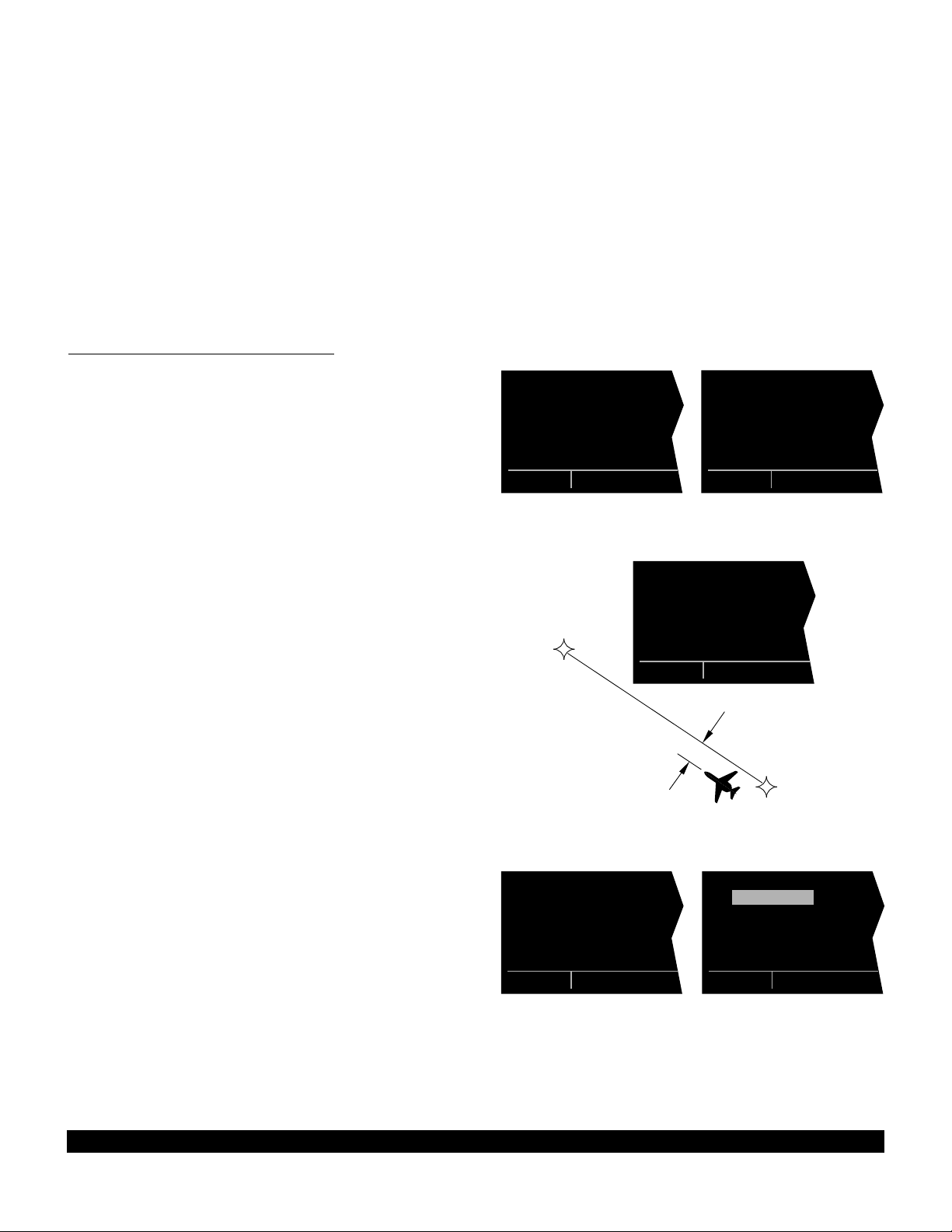
3.9 THE NAVIGATION PAGES
As you would expect, the NAV (navigation) pages contain
information relating specifically to the KLN 90B’s navigation capabilities. The KLN 90B has five NAV pages.
Unlike any other pages, these pages may be selected
and viewed on both the left and right sides of the screen.
The procedure for selecting specific pages, including the
NAV pages, was described in section 3.4.1, “Page
Selection.” This section will cover all NAV pages except
for the NAV 4 page (Vertical Navigation) which is
explained in section 5.2.
3.9.1 The Navigation 1 Page (NAV 1)
A NAV 1 page is shown in figure 3-97. A NAV 1 page
displays the following information:
• The active navigation leg. For Direct To operation this
consists of the Direct To symbol, d, followed by the
active Direct To waypoint identifier (figure 3-97). For
the leg of a flight plan this consists of the “from” waypoint identifier and the active “to” waypoint identifier
(figure 3-98). An arrow (>) precedes the active waypoint identifier.
• A course deviation indicator (CDI) that displays left
and right deviation from the desired track. A vertical
bar operates like a navigation deviation needle on a
conventional CDI or HSI. An on-course indication is
displayed when the vertical deviation bar is centered
on the triangle in the middle of the CDI. In both
modes each dot represents one nautical mile deviation from the desired track. Therefore, the CDI shows
course deviation five nautical miles left and right of
course. A vertical deviation bar positioned two dots to
the right of the center triangle indicates the aircraft is
two nautical miles to the left of course (figure 3-99).
The center triangle also serves as the CDI’s
TO/FROM indicator and operates in the same manner
as a conventional CDI TO/FROM indicator; an “up” triangle indicates “to” the active waypoint while a “down”
triangle (figure 3-100) indicates “from” the active waypoint. The word “FLAG” is displayed over the CDI
when the KLN 90B is not usable for navigation (figure
3-101).
NOTE: It is possible to change the CDI scale factor to be
0.2 nm per dot or 0.06 nm per dot. See section 5.9.8.
• Distance (DIS)to the active waypoint.
• Groundspeed (GS)
• Estimated time enroute (ETE)
$=KOSH |
+++++Ê+++++|
DIS 683nm|
GS 193kt|
ETE 3:34|
BRG 303^|
NAV 1
Figure 3-97
KOSH
=KOSH |
+++++Ï+++++|
DIS 18nm|
GS 193kt|
ETE :06|
BRG 123^|
NAV 1
Figure 3-100
KHPN =KOSH |
+++++Ê+++++|
DIS 683nm|
GS 193kt|
ETE 3:34|
BRG 303^|
NAV 1
Figure 3-98
KHPN =KOSH |
+++++i+fl+++|
DIS 683nm|
GS 193kt|
ETE 3:34|
BRG 303^|
NAV 1
2 NM
KHPN
Figure 3-99
|
++F L A G++|
DIS --.-nm|
GS ---kt|
ETE --:--|
BRG ---^|
NAV 1
Figure 3-101
• Bearing (BRG)to the active waypoint.
3-31
Rev 1
Page 54

3.9.2 The Super NAV 1 Page
When the NAV 1 page is selected on both the left and
right sides at the same time, the Super NAV 1 page is
displayed (figure 3-102). The Super NAV 1 page contains
exactly the same information as the standard NAV 1 page
but spreads the data out across the entire screen making
it even easier to view. The word “FLAG” is displayed over
the CDI when the KLN 90B is not usable for navigation.
3.9.3 The Navigation 2 Page (NAV 2)
The NAV 2 page in figure 3-103 displays the aircraft’s
present position in two formats. The first format is in
terms of the distance and radial from a nearby VOR.
(Although terminal VORs are in the database, they are
not used on this page since many aeronautical charts do
not display a compass rose around them for orientation
purposes). The second format is in latitude and longitude.
NOTE: When flying non-precision approach procedures
that contain DME arcs, the VOR/DME station that defines
the arc is always displayed on the NAV 2 page even if the
reference is a terminal VOR/DME. This occurs when the
aircraft is within 30 NM of the arc.
3.9.4 The Navigation 3 Page (NAV 3)
The NAV 3 page, such as shown in figure 3-104, displays
the following supplementary navigation information:
• Desired track (DTK) - The great circle course between
two waypoints. Any CDI or HSI driven by the KLN
90B, including the CDI displayed on the NAV 1 page,
is referenced to this DTK. You may wish to view the
navigation terminology diagram in Appendix A at this
time if you are unfamiliar with terms like desired track
and actual track.
NOTE: If the KLN 90B is in the OBS mode, the selected
course (OBS) is displayed instead of the desired track on
the NAV 3 page (figure 3-105).
• Actual track(TK)- The aircraft’s present track over the
ground. Note: If there is insufficient velocity, the KLN
90B will display dashes (- - -) instead of the actual
track.
$=KOSH
DIS 683nm ETE 3:34
GS 193kt BRG 303^
NAV 1 enr-leg NAV 1
Figure 3-102
PRESENT POS|
|
LGA 045^fr|
15.2nm|
N 41^00.03'|
W 73^41.62'|
NAV 2
Figure 3-103
$=OSH |
DTK 303^|
TK 302^|
FLY L 2.7nm|
MSA 3300ft|
ESA 5500ft|
NAV 3
Figure 3-104
=KOSH |
OBS 281^|
TK 302^|
FLY R 0.2nm|
MSA 3000ft|
ESA 3700ft|
NAV 3
Figure 3-105
• Cross track error correction - This is a text means of
indicating how far and which direction to get back on
course. It is consistent with the vertical deviation bar
displayed on the NAV 1 page. “FLY L 2.7 NM”
means fly left 2.7 nautical miles to get on course.
3-32
Rev 1
Page 55

• Minimum Safe Altitude for present position (MSA) IMPORTANT:The minimum safe altitude displayed
is the altitude defined by Jeppesen as “Grid Minimum
Off-Route Altitude (Grid MORA)”. This altitude is
derived by Jeppesen for sectors which are one degree
of latitude by one degree of longitude in size. One
degree of latitude is 60 nautical miles. One degree of
longitude is 60 nautical miles at the equator and progressively less than 60 nautical miles as one travels
away from the equator. One degree of longitude is
approximately 50 nautical miles at the southern most
parts of the U.S. and is approximately 40 nautical
miles at the northern most parts of the U.S. The MSA
altitude information is contained in the database and
is updated when the database cartridge is updated.
The minimum safe altitude (MSA) provides “reference
point” clearance within these one degree latitude by
one degree longitude sectors. Jeppesen defines a
reference point as “a natural (Peak, Knoll, Hill, Etc.) or
man-made (Tower, Stack, Tank, Building, etc.)
object”. Jeppesen states the following about the Grid
Minimum Off-Route altitude: “Grid MORA values
clear all reference points by 1000 feet in areas where
the highest reference points are 5000 feet MSL or
lower. MORA values clear all reference points by
2000 feet in areas where the highest reference points
are 5001 feet MSL or higher”. The KLN 90B displays
dashes for areas outside the database coverage area
or for areas where the Grid MORA is not defined.
• Minimum Enroute Safe Altitude (ESA). IMPORTANT:
When the KLN 90B is in the Leg mode, the minimum
enroute safe altitude is the highest MSA sector altitude from the present position to the active waypoint,
then to the destination waypoint along the active flight
plan. See figure 3-106. When the KLN 90B is in the
OBS mode, the minimum enroute safe altitude is the
highest MSA sector altitude from the present position
to the active waypoint.
WARNING: The MSA and ESA altitudes displayed are
advisory in nature only. They should not be relied
upon as the sole source of obstacle and terrain
avoidance information. Refer to current aeronautical
charts for appropriate minimum clearance altitudes.
MSA (MSL)
1° LONG.
MINIMUM ENROUTE SAFE ALTITUDE (ESA)
ESA (MSL)
1°
LAT.
Figure 3-106
3-33
Rev 1
Page 56

3.9.5 The Navigation 4 Page (NAV 4)
The NAV 4 page (figure 3-107) is used for altitude alerting
and for advisory vertical navigation (VNAV). The operation of altitude alerting is described in section 3.15 and
the operation of VNAV is described in section 5.2.
3.9.6 The Navigation 5 Page (NAV 5)
The NAV 5 page provides a navigation graphics presentation. It is useful in providing you with proper orientation
of the navigation situation. In all KLN 90B installations
there are three common map orientation formats that may
be selected on the NAV 5 page: a True North up display,
a desired track up display, or an actual track up display.
In addition, if the KLN 90B is interfaced with a source of
heading in a compatible format then a heading up presentation may also be selected. When the North up display is selected, viewing the NAV 5 page is like looking at
a navigation chart with North at the top. When the
desired track up display is selected, viewing the NAV 5
page is like looking at a chart that is turned so that your
course line is always pointing up. When the actual track
up display is selected, viewing the NAV 5 page is like
looking at a chart that is turned so that the direction the
aircraft is tracking over the ground is pointing up. In a no
wind condition, actual track is identical to the aircraft’s
heading.
CAUTION: When using the actual track up format it
is typical for there to be a slight delay from the time a
heading change is made until the correct map orientation is displayed. Be careful when using either the
desired track up display or the actual track up display
to not think that a heading up display is being used.
VNV 6200ft|
|
IND 6300ft|
SEL: 3500ft|
KOSH :-03nm|
ANGLE:-1.8^|
NAV 4
Figure 3-107
1:KMDT |
4
; 2:LRP |
< 3:MXE |
3
4:KPHL |
5: |
|123^ 40
2
FPL 0 enr-leg NAV 5
Figure 3-108
|
1
|
|
|
*
2
i
j
3
4
|
NŸ 40|
NAV 5
Figure 3-109
In chapter 4 of this Pilot’s Guide you will learn to use flight
plan operation where the NAV 5 page really becomes
useful. When navigating using flight plan operation, the
active flight plan (FPL 0) waypoints are displayed using
the number associated with the waypoint as it appears on
the FPL 0 page (figure 3-108). Thus, the position of the
third waypoint in FPL 0, MXE, is indicated by a 3 on the
NAV 5 page. Lines connect the flight plan waypoints. An
arrow points to the active waypoint and shows the current
flight plan leg.
When operating Direct To a waypoint which is not in the
active flight plan the Direct To waypoint is indicated on
the NAV 5 page by an * (figure 3-109).
To select the desired NAV 5 orientation, press the appropriate C(left Cif NAV 5 page is on left side and vice
versa). The cursor will be over the map range scale (figure 3-110). Turn the appropriate outer knob one step
counterclockwise to position the cursor over the map orientation field (figure 3-111). Rotate the appropriate inner
|
1
|
2
|
|
i
j
3
4
|
NŸ 40|
CRSR
Figure 3-110
|
1
|
2
|
|
i
j
3
4
|
NŸ 40|
CRSR
Figure 3-111
3-34
Rev 1
Page 57
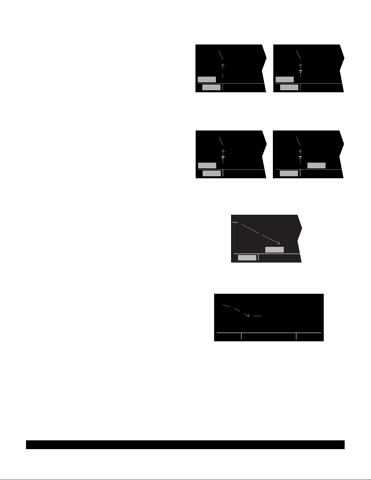
knob to display N?for North up, DTK?for desired track up
(figure 3-112), TK?for actual track up (figure 3-113), or
HDG?for heading up (figure 3-114). The heading up
selection is not presented as a choice if heading is not
provided to the KLN 90B. If the cursor is moved to the
map range scale using the outer knob or if the cursor is
turned off with the Cbutton, then the DTK?, TK?, or
HDG?annunciation is replaced with the actual value. The
123 °displayed in the lower left corner of figure 3-115
shows how the actual track is displayed when the cursor
is not over the map orientation field as it was in figure 3-
113.
|
4
|
|
|
|
DTKŸ 40|
3
i
j
2
CRSR
Figure 3-112
|
4
|
|
3
|
|
TKŸ 40|
2
CRSR
Figure 3-113
If a heading input is available to the KLN 90B then heading up is usually the best map orientation to select.
Otherwise, track up display is usually preferred for use in
flight. However, the track up display is only usable when
the aircraft is moving 2 knots or more so the North up display may be a good choice while operating with very slow
ground speeds.
Notice that in both the North up format and the desired
track up format, the aircraft’s position is depicted by a diamond. In the actual track up format and the heading up
format, the aircraft’s position is depicted by an aircraft
symbol.
The range scale is displayed in the lower right corner of
the NAV 5 page. The range scale indicates the distance
from the aircraft’s position (the diamond or aircraft symbol) to the top of the screen. Range scale selections from
1 NM to 1000 NM may be made by pressing the appropriate Cand turning the appropriate inner knob. For
example, figure 3-116 illustrates the results of changing
the range scale of the map in figure 3-110 from 40 nautical miles to 15 nautical miles.
When the NAV 5 page is displayed on the left side of the
screen and any selected waypoint page is displayed on
the right side, the location of the selected waypoint is indicated by a “+” on the NAV 5 page (figure 3-117). Of
course, the display scale must be chosen which allows
the selected waypoint to be displayed.
|
4
|
|
3
|
|
HDGŸ 40|
2
CRSR
Figure 3-114
|
2
|
|
|
|
NŸ 15|
CRSR
| PTW D
1
+ |POTTSTOWN
2
| L
|116.50 9^W
i
j
|N 40^13.33'
NŸ 40|W 75^33.64'
NAV 5 enr-leg VOR
|
|
|
|
|
123^ 40|
CRSR
i
j
Figure 3-116
4
3
Figure 3-117
4
3
2
Figure 3-115
3
3-35
Rev 1
Page 58

3-36
Rev 1
3.9.7 The Super NAV 5 Page
Regardless of whether you ultimately learn to use just the
Direct To capabilities of the KLN 90B or whether you
master all of its sophisticated features, you will definitely
want to learn how to use the Super NAV 5 page! The
Super NAV 5 page provides you with a true moving map
display of your present position and route of flight in
relation to nearby navaids and airports. The Super NAV
5 page is displayed by selecting the NAV 5 page on both
the left and right sides at the same time (figure 3-118).
As you can see, the Super NAV 5 page has a unique format unlike any other KLN 90B page. This is done so that
you get the maximum amount of screen dedicated to
graphics display. There are no page display indicators in
the lower left and right segments of the display to tell you
the Super NAV 5 page is being displayed. However, you
will soon learn to recognize the Super NAV 5 page by its
unique format. The mode annunciation, which normally
appears in the lower center segment of the screen, is now
located on the far left side. The message prompt is now
located in the lower left corner of the graphics display.
The left side of the Super NAV 5 page shows the
following information:
• Distance to the active waypoint
• The active waypoint identifier
• Mode of operation
• Groundspeed
• *Estimated time enroute, cross track error, or VNAV
status
• *Desired track, bearing to active waypoint, or radial
from active waypoint
• *Actual track, bearing to active waypoint, or radial from
active waypoint
The lines above with an * in front can be configured by
the pilot to display any of the items listed. This is done by
pressing the left C and rotating the left outer knob counterclockwise until it is over the desired line. Turn the left
inner knob to choose between items for a given line.
When all selections are complete, turn off the cursor by
pressing the left C.
The map scale is also changed by using the left cursor
button. To change the map scale, press the left C to
place the cursor over the map scale factor at the bottom
left corner of the map display. Turn the left inner knob to
select a map scale. The map scale choices are the same
as for the NAV 5 page except there is an additional
choice, AUTO, that is located between the 1 and 1000
nm scale factors. The AUTO scale factor will automatically choose the smallest map scale that will display the
active waypoint and, if there is one, the waypoint after the
active waypoint. Choosing the AUTO scale factor means
there is one less item for you to worry about. This is especially helpful when conducting non-precision approaches
using the KLN 90B.
9.2 oq
LRP |
xy-«} |
200 uv
áà0:03|
ûü113^|
†ü113^|60
KMDT
LRP
MXE
KPHL
Figure 3-118
Page 59

Like the NAV 5 page, the Super NAV 5 page shows a
graphics depiction of the direct to waypoint or the waypoints making up the active flight plan. But surprise number one is that the Super NAV 5 page shows alphanumeric waypoint identifiers on the graphics display to make
orientation even easier for you.
Now surprise number two. You may elect to have nearby
VORs, NDBs, and/or airports added to the graphics display! To do so, press the right Cto display a pop up
menu on the right side of the screen (figure 3-119).
Notice from the menu that a circle with a dot in the center
represents a VOR, a smaller circle represents a NDB,
and a small diamond represents an airport. The VORs,
NDBs, and airports displayed are those from the nearest
waypoint lists described in section 3.7.3, “Nearest and
Complete Waypoint Scan Lists.”
When the menu is first displayed the cursor will be on the
VOR selection field. Rotate the right inner knob to display
one of the following: TLH, LH(figure 3-120),H, or OFF.
TLHTerminal, low altitude, and high altitude VORs are
selected. In addition, VORs of undefined class will
be displayed. In some parts of the world VORs are
not classified into one of the three standard classes:
therefore, TLH must be selected to display these
undefined class VORs.
8.6 oq VOR:OFF
LRP | NDB:OFF
xy-«} | APT:OFF
200 uv 113^†üŸ
áà0:03|
LRP
ûü113^|
†ü113^|60
KMDT
Figure 3-119
8.6 oq VOR: LH
LRP | NDB:OFF
xy-«} | APT:OFF
200 uv 113^†üŸ
áà0:03|
ûü113^|
†ü113^|60
ETX
LRP
RAV
KMDT
Figure 3-120
LHOnly low altitude and high altitude VORs will be dis-
played.
H Only high altitude VORs will be displayed.
OFFNo VORs displayed
In a like manner NDBs and/or airports may be selected
by first using the right outer knob to move the cursor over
the NDBor APTselection field and then using the right
inner knob to select ONorOFF. The example in figure
3-121 shows low and high altitude VORs as well as NDBs
having been selected. Notice that the range scale has
been changed from 60 nm to 40 nm.
The map orientation can be changed by moving the cursor to the bottom line of the pop-up menu and rotating the
right inner knob. The map orientation choices are the
same as for the NAV5 page: North up, desired track up,
actual track up, or heading up (if a proper source of heading is provided). Remember that for actual track up,
graphics are displayed only when the aircraft’s groundspeed is greater than 2 knots.
When the desired selections have been made, press the
right Cto remove the menu (figure 3-122).
LQX
AB
ETX
LRP
RAV
BZJ
8.6 oq VOR: LH
LRP | NDB: ON
xy-«} | APT:OFF
200 uv 113^†üŸ
áà0:03|
ûü113^|
†ü113^|40
Figure 3-121
LQX
AB
ETX
LRP
BZJ
RAV
APG
9.1 oq
LRP |
xy-«} |
200uv
áà0:03|
ûü113^|
†ü113^|60
Figure 3-122
3-37
Rev 1
Page 60

The last surprise for this page is that it is possible for you
to change the active waypoint to any of the flight plan
waypoints without having to leave this very useful page.
This is done by pulling on the right inner knob to place it
in the “out” position. This will create a “window” at the
bottom right corner of the display that will initially contain
the active waypoint in reverse video (figure 3-123). The
waypoint contained in this “window” will be the default
waypoint when Dis pressed. By turning the right inner
knob it is possible to scan through the waypoints of the
active flight plan. Turning the knob clockwise will scan
through the waypoints in sequence until the end of the
flight plan is reached. Turning the knob counter-clockwise
will scan through the active flight plan in reverse order
until the beginning of the flight plan is reached. Pushing
the right inner knob back to the “in” position will remove
the “window” from the graphics portion of the display. An
example of how to use this technique is presented in section 4.3.2.
The following operational hints will make using the Super
NAV 5 more enjoyable.
• It is easy to clutter the display with so much data that
it is unusable. Select a range scale that allows an
uncluttered presentation of the chosen VORs, NDBs,
and airports. Or, select another combination of VORs,
NDBs, and airports from the menu. Experiment and
continue to make new selections for different phases
of your trip. For example, you may find that in the
enroute part of the flight selecting high altitude VORs
provide you with enough information, while in the terminal area you select a smaller range scale and select
more items.
LQX
AB
ETX
LRP
BZJ
RAV
APG
9.0 oq
LRP |
xy-«} |
200 uv
áà0:03|
ûü113^|
†ü113^|40 LRP
Figure 3-123
• Press @to instantly declutter the VOR, NDB, and
airport selections from the graphics display. Flight
plan and Direct To waypoints will still be displayed.
Press @again to restore the selections.
• While taxiing on the airport or flying in the traffic pattern, select the 1 NMor 2 NMscale to display the airport runway diagram instead of the usual airport diamond symbol. All runway designations are shown on
the 1 NMscales (figure 3-124). If the 2 NM scale is
selected, then the runway designations are shown
only for the longest runway. If your KLN 90B is not
provided a heading input you may wish to select a
North up display while the aircraft is on the airport
since an actual track up graphics presentation can
only be displayed when the aircraft is moving at least
2 knots.
CAUTION: The NAV 5 and Super NAV 5 pages do not
display weather, terrain, special use airspace, or
other data.
355 oq
14R
KTIK |
xy-«} |
i
0 uv
áà-\--|
ûü039^|
†ü---^|1
32L
KRND
j
32R
Figure 3-124
3-38
Rev 1
Page 61

3-39
Rev 1
3.10 SPECIAL USE AIRSPACE ALERT
The KLN 90B database contains the location of areas of
special use airspace (SUA). The types of SUA areas
stored in the database and the abbreviations used to
denote these areas are the following:
Class B CL B
Class C CL C
Control Area (used outside USA) CTA
Terminal Area (used outside USA) TMA
Alert Area ALRT
Caution Area CAUT
Danger Area DNGR
Military Operations Area MOA
Prohibited Area PROH
Restricted Area REST
Training Area TRNG
Warning Area WARN
The KLN 90B will normally alert you prior to entering one
of these areas with a message prompt. When the
Message page is viewed it will display AIRSPACE
ALERT and will also display the name and type of the
special use airspace (figure 3-125). If the special use airspace is a Class B, Class C, CTA, or TMA, the message
page will also instruct you to see the Airport 4 page (airport communications) for the primary airport so that the
correct communications frequency may be determined
(figure 3-126).
The SUA alert feature is three dimensional. The SUA
areas are stored in the KLN 90B database with regard to
altitude when the actual SUA altitude limitations are
charted in terms of mean sea level (MSL). Therefore, if
you are flying either above or below an SUA area you
won’t be inconvenienced with nuisance alert messages.
However, if the actual lower limit of a SUA is charted in
terms of an altitude above ground level (AGL), then it is
stored in the KLN 90B as all altitude below the upper limit
of the SUA. If the actual upper limit of an SUA is charted
in terms of AGL, it is stored in the KLN 90B as “unlimited”.
If the altitude input to the KLN 90B is pressure altitude
from an altitude encoder or air data computer, then you
must manually update the KLN 90B with an altimeter setting (baro correction) in order to receive accurate SUA
alerting. You may easily update the altimeter setting by
pressing the A button to display the Altitude page
(figure 3-127). The cursor will be over the inches field if
“inches” was previously selected on the SET 7 page. If
“millibars” was selected on the SET 7 page then the cursor will be over the first two digits of the millibar field. The
left inner knob is used to change the digits and the left
outer knob is used to move the cursor to the desired position. When the altimeter setting is complete, press A to
return to the pages previously in view.
CAUTION: Failure to keep the altimeter baro setting
updated will result in inaccurate special use airspace
alerting. If this feature is used, it is a good idea to
ALTITUDE |
|
BARO:29.92"|
ALERT: OFF |
|
|
CRSR
Figure 3-127
AIRSPACE ALERT:
COLUMBUS FOUR MOA
MEM CENTER
1000ft t] 18000ft
enr-leg msg
Figure 3-125
AIRSPACE ALERT:
OMAHA CL C
SEE KOMA APT 4 PAGE
BELOW 5000FT
enr-leg msg
Figure 3-126
Page 62

update the altimeter baro setting on the ALT page
each time you make a change to an aircraft’s altimeter setting.
NOTE: If there is no altitude input to the KLN 90B, all alti-
tudes will be regarded as being within the boundary of the
SUA area.
Only the outer lateral boundaries are stored for Class B,
Class C, CTA, and TMA airspace. These SUA areas are
stored as “cylinders” of airspace so all altitudes below the
upper limit of these areas are considered to be in the
SUA.
SPECIAL USE AIRSPACE ALERT
The message prompt for a special use airspace alert will
occur when the aircraft’s position is at a point such that a
projection of the aircraft’s existing track over the ground is
approximately 10 minutes from penetrating the outer
boundary of one of these areas. It will also occur if the
aircraft is within approximately two nautical miles of one
of these areas even if the aircraft’s projected track over
the ground won’t actually penetrate the SUA area (figure
3-128). If one of the SUA areas is penetrated, another
message will state: INSIDE SPC USE AIRSPACE.
2 MILES
10 MIN
Figure 3-128
3-40
Rev 1
Page 63

3-41
Rev 1
The SUA alert feature may be disabled (or enabled) on
the Setup 8 (SET 8) page, shown in figure 3-129. After
displaying the SET 8 page on the left side, press the left
C to turn on the left cursor function. The left inner knob
is used to display AIRSPACE ALERT ENABLE or AIR-
SPACE ALERT DISABLE.
If the SUA alert feature has been enabled, the KLN 90B
allows you to select a vertical buffer on the SET 8 page
(figure 3-130) in order to provide an additional layer of
protection from inadvertently entering a SUA area. To
select a vertical buffer, make sure the SUA alert feature
has been enabled. Press the left C to turn on the left
cursor and then use the left outer knob to move the cursor over the first position of the vertical buffer (figure 3-
131). Use the left outer knob to position the cursor and
the left inner knob to select each number (figure 3-132).
The buffer may be selected in one hundred foot increments. After the desired selection has been made, press
the left C to turn off the cursor function.
The vertical buffer serves to “stretch” the SUA area in
both directions by the selected buffer altitude. For example, let’s say you have selected a buffer of 1000 feet and
the actual SUA area exists from 5,000 feet MSL to 12,000
feet MSL. In this case you will receive SUA alert messages if you fly at any altitude between 4,000 and 13,000
feet MSL.
CAUTION: It is the pilot’s responsibility to avoid
those areas of special use airspace where ATC clearance to penetrate is required but has not been
obtained. The KLN 90B’s special use airspace alert is
only a tool to assist the pilot and should never be
relied upon as the sole means of avoiding these
areas.
NOTE: Special Use Airspace alerting is disabled when in
the approach arm or approach active modes.
AIRSPACE |
ALERT |
ENABLE |
|
VERT BUFFER|
±00500ft|
SET 8
Figure 3-130
AIRSPACE |
ALERT |
DISABLE |
|
|
|
SET 8
Figure 3-129
AIRSPACE |
ALERT |
ENABLE |
|
VERT BUFFER|
±00500ft|
CRSR
Figure 3-131
AIRSPACE |
ALERT |
ENABLE |
|
VERT BUFFER|
±01000ft|
CRSR
Figure 3-132
Page 64

3.11 VIEWING THE WAYPOINT PAGES
You learned in section 3.7, “SELECTING WAYPOINTS”,
the different means of selecting the desired waypoint.
You will now see what information may be displayed for
each of the waypoint types (airport, VOR, NDB, intersection, and supplemental).
3.11.1 Airport Pages
There are eight airport pages (APT 1, APT 2, ..., APT 8)
for every airport in the published database. The database
primary area contains public use and military airports that
have a runway at least 1000 feet in length (see section
2.2, "Database Coverage Areas and Contents"). We will
use Orlando Executive airport to illustrate what is
contained on the airport pages.
3.11.2 The Airport 1 Page (APT 1)
See figure 3-133.
• Airport identifier. An arrow precedes the identifier if it
is the active waypoint.
• Airport name.
• If the airport underlies the outer boundary of a Class B
or C airspace, CTA (Control Area - used outside
USA), or TMA (Terminal Area - used outside USA),
the letters CL B, CL C, CTA, or TMA, respectively,
will appear on the left side of this line. Note that there
is no altitude information applied to this criteria.
In addition, if the airport is a military airport the letters
MILTRYwill appear on the right side of this line. If the
airport is a private airport, the letters PRIVAT will
appear.
• The latitude and longitude of the airport reference
point (the “official” location of the airport).
As shown in figure 3-134, the APT 1 page has a different
format when it is displayed as one of the nine nearest airports (see section 3.7.3 “Nearest And Complete Waypoint
Scan List” and section 3.7.3.1 “Nearest Airports In An
Emergency”.
|=KORL
|EXECUTIVE
|
|CL B
|N 28^32.71'
|W 81^19.99'
Figure 3-133
|=KORL nr 1
|EXECUTIVE
|
| 5998' HRD
|L 132^t]
| 03.1nm
Figure 3-134
• To the right of the airport identifier are the letters “NR”
followed by a number designating the nearest airport
(NR 1), second nearest airport (NR 2), etc. to the air-
craft’s present position.
• The length, surface, and lighting of the longest runway.
• The bearing and distance to the airport.
3-42
Rev 1
Page 65

3.11.3 The Airport 2 Page (APT 2)
See figure 3-135.
• Airport identifier. An arrow precedes the identifier if it
is the active waypoint.
• The city where the airport is located.
• The state if the airport is located in the United States,
the Province if located in Canada, or the country outside the United States and Canada. A listing of the
abbreviations used for States, Provinces, and countries is contained in Appendix D.
• Airport elevation. The elevation is rounded to the
nearest 10 feet.
• Time in relationship to UTC (Zulu). Z-05, for example,
indicates local standard time is five hours behind UTC
time. If the airport is located in an area which
observes daylight savings time, the information in
parentheses shows the daylight savings time in relationship to UTC.
• Instrument approach information.
ILS - airport has an ILS approach.
MLS - airport has an MLS approach.
ILS/MLS- airport has ILS and MLS approaches.
NP APR- airport has a non-precision approach
and no ILS or MLS.
NO APR- airport does not have an instrument
approach.
|=KORL
|ORLANDO FL
|
|ELV 110ft
|Z-05(-04DT)
|ILS (R)
APT 2
Figure 3-135
• The symbol (R) designates that the airport is serviced
by an Approach/Departure control facility having radar
capability. If you are on an instrument flight plan, you
know whether to expect vectors to the final approach
course or whether you will have to do your own transition. If you are VFR, you know whether or not the
Approach/Departure control is capable of providing
separation advisories.
3.11.4 The Airport 3 Page (APT 3)
The function of the APT 3 page is to display runway information for the selected airport. For many airports the first
APT 3 page depicts a North up runway diagram for the
airport as shown in figure 3-136 for KORL.
NOTE: This runway diagram is present only for those airports where Jeppesen’s data contains the position of the
runway thresholds
.
|
13
|
|
25
|
|
07
|
31
APT[3
Figure 3-136
3-43
Rev 1
Page 66

3-44
Rev 1
The primary APT 3 page (figure 3-137) follows the runway diagram. Runway designation, lighting, and types of
surface for up to five runways are displayed in order of
length, beginning with the longest. Since there are many
times when all of an airport’s runway information does not
fit on one page, additional APT 3 pages are used to display the data. Remember that a “+” inserted between the
page type and the number (APT+3 in this case) is used to
indicate that there is more than one Airport 3 page.
• The letters “RT” followed by a runway designation
indicate that the runway normally has a right hand
traffic pattern. In figure 3-137, RT 25 31 designates
that runways 25 and 31 have a right hand traffic pattern.
• Runway number designation for both ends of the runway.
• Runway lighting availability.
L - runway lighting sunset to sunrise
LPC - runway lighting is pilot controlled
LPT - runway lighting is part-time or on-
request
-blank indicates no runway lighting
• Runway length in feet.
• Runway surface:
HRD - hard surface (includes asphalt,
concrete, pavement, sealed, tarmac, brick,
and bitumen)
TRF - turf
GRV - gravel
CLY - clay
SND - sand
DRT - dirt
ICE - ice
MAT - steel matting
SHL - shale
SNW - snow
- Blank indicates runway surface
type is unknown.
In the event that there is no runway information for an
airport, the following message is displayed on the APT 3
page:
RUNWAY DATA NOT AVAILABLE
|=KORL
| RT 25 31
|07 /25 L
| 5998' HRD
|13 /31 L
| 4638' HRD
APT[3
Figure 3-137
Page 67

3.11.5 The Airport 4 Page (APT 4)
See figure 3-138
The APT 4 page is used to display communication fre-
quencies for the selected airport.
• Airport identifier. An arrow precedes the identifier if it
is the active waypoint.
• Frequencies for:
ATIS - automatic terminal information service
PTAX- pre-taxi clearance
CLR - clearance delivery
GRND- ground control
RAMP- ramp/taxi control
TWR - tower
UNIC - unicom
MCOM- multicom
CTAF- common traffic advisory frequency
RDO - radio
MF - mandatory frequency
ATF - aerodrome traffic frequency
AFIS - aerodrome flight information service
CL B - Class B (VFR frequency)
CL C - Class C (VFR frequency)
TRSA- terminal radar service area (VFR
frequency)
CTA - control area (VFR frequency used out
side USA)
TMA - terminal area (VFR frequency used
outside USA)
APR - approach control
DEP - departure control
CTR - center (when center is used for
approach/departure control)
ARVL- arrival
RDR - radar only frequency
DIR - director (approach control/radar)
ASOS- automated surface observation system
AWOS- automatic weather observing station
AAS - aeronautical advisory service
PCL - pilot controlled lighting
|=KORL
|ATIS*127.25
|CLR *118.05
|GRND*121.40
|TWR *118.70
|CTAF*118.70
APT[4
Figure 3-138
In addition to the standard VHF frequencies shown in figure 3-138, HF frequencies are shown at airports that utilize “high frequency” communications that fall in the 2000
kHz to 30,000 kHz frequency band. These are typically
used in remote areas of the world. One way to tell HF
frequencies is that they do not contain a decimal point. A
display of 6547would indicate a frequency of 6,547 kHz.
Airports which have numerous communication frequencies will have multiple Airport 4 pages indicated by
APT+4.
Part-time operation, such as for a control tower, is indicated with an*to the left of a frequency.
3-45
Rev 1
Page 68

3-46
Rev 1
The frequencies associated with CL B, CL C, TRSA,
CTA, or TMA are VFR frequencies. Airports which have
one of these categories of frequencies also have APR
and DEP which are IFR frequencies.
Where required, APR, DEP, CL B, CL C, TRSA, CTA,
and TMA frequencies are sectorized. That is, a frequency may be used only within a certain range of radials
from a designated reference location. The format for displaying the sectorization is to show the frequency first, followed by the identifier of the associated reference point,
followed next by the associated altitude restrictions. For
example, figure 3-139 shows that the Orlando approach
control frequency 121.10 MHz is used between the 311°
radial and the 60° radial from KMCO (Orlando
International airport) for altitudes at and below 5500 feet.
NOTE: When an altitude restriction is shown on the
Airport 4 page, the abbreviation BEL means at and below
the specified altitude. Likewise, the abbreviation ABV
means at and above the specified altitude. Thus, ABV
4000FT means at and above 4000 feet and BEL 3999ft
means at and below 3999 feet.
In a few cases, APR, DEP, CL B, CL C, TRSA, CTA, and
TMA frequencies are sectorized such that the restriction
cannot be displayed on a single page. When this occurs
the following message is displayed on the APT 4 page:
TEXT OF FREQUENCY USAGE NOT DISPLAYED
There are also some airports in the database for which no
communications information is available. The following
message is then displayed on the APT 4 page:
COMM FREQ DATA NOT AVAILABLE
|=KORL
|APR 121.10
| REF: KMCO
| 311^- 60^
| BEL 5500ft
|
APT[4
Figure 3-139
Page 69

3-47
Rev 1
3.11.6 The Airport 5 Page (APT 5)
The Airport 5 page is used to store and display userentered remarks. These remarks might include information on lodging, dining, airport services, or anything else
you desire to record for later use. Up to 100 airports may
contain these remarks. A remark may contain up to three
lines of eleven characters each. Letters, numbers,
hyphens, and spaces may be used in the remark. To
enter a remark:
• Select the APT 5 page for the desired airport (figure
3-140).
• Press the right C .
• Rotate the right outer knob until the cursor fills the
entire third line of the screen (figure 3-141).
• Use the right inner knob to select the first character of
the remark.
• Use the right outer knob to move the flashing portion
of the cursor to the second cursor position, and then
use the right inner knob to select the second character.
• Use the right outer and inner knobs to select the rest
of the first line of the remark (figure 3-142).
• Press E to approve the first line. The cursor will
move to the next line (figure 3-143).
• Use the above procedure to select the characters for
the second and third lines of the remark. Press E to
individually approve each line of the remark.
• Press the right C to turn the right cursor function off
(figure 3-144).
The Other 4 page (OTH 4) includes a listing of all airports
whose APT 5 pages contain remarks (figure 3-145). To
delete a previously entered airport remark, select the
Other 4 page, position the left cursor over the desired airport identifier, press @, and then press E. If there are
more than five airports with remarks, you will have to use
the left outer knob to scroll the cursor down the list on the
Other 4 page to find the desired airport identifier.
|=KORL
|REMARKS:
| BESTJET!!
|
|
|
CRSR
Figure 3-142
|=KORL
|REMARKS:
| BESTJET
|
|
|
CRSR
Figure 3-143
|=KORL
|REMARKS:
| BESTJET
| MOTEL 407
| 123-4567
|
APT 5
Figure 3-144
APTS W/RMKS|
KCOS |
KDEN |
KORL |
KHPN |
M39 |
OTH 4
Figure 3-145
|=KORL
|REMARKS:
|
|
|
|
APT 5
Figure 3-140
|=KORL
|REMARKS:
|
|
|
|
CRSR
Figure 3-141
Page 70

3-48
Rev 1
3.11.7 The Airport 6 Page (APT 6)
The APT 6 page shows aeronautical services available for
the selected airport. These services include customs, fuel,
and oxygen availability as well as an indicator to denote
the presence of a landing fee. Refer to figure 3-146.
• Customs information is displayed as follows:
CUSTOMS-FULL Customs facilities are available
without restriction
NO CUSTOMS No customs facilities are
available
CUSTMS-PR Customs facilities are available
but require prior request or
permission for use
CUSTMS-REST Customs facilities are available
on a restricted basis, check
with the airport before planning
to use
CUSTMS-ADCS Customs are available for
private aircraft arriving to the
U.S.from Canada or Mexico.
Advance notice of arrival to
customs officers is to be
included in the flight plan
transmitted to an FAA facility.
This code is used when this is
the only type customs facility
available. The FAA term for
the service is “ADCUS”.
(blank) Blank line indicates that customs
information is not available in the
database.
• The following fuel types are displayed:
80 80 octane
100 100 octane
100LL 100 octane, low-lead
MOGAS Automotive fuel
JET Jet fuel (any type jet fuel qualifies)
NO FUEL No fuel available
• If there are no oxygen services available at the
selected airport, the fifth line will display NO OXYGEN.
If any type of oxygen service is available, the fifth line
will read OX and the rest of the line will display the specific oxygen service:
H high-pressure
HB high-pressure bottled
L low-pressure
LB low-pressure bottled
ALL all of the above oxygen
services available
• The sixth line of the APT 6 page denotes the presence
of a landing fee:
LANDING FEE The airport has a landing fee
NO LDG FEE The airport does not have a
landing fee
NO FEE INFO Jeppesen does not have any
information on whether
or not there is a landing fee for
this airport
|=KORL
|
|100 JET
|
|NO OXYGEN
|NO FEE INFO
APT 6
Figure 3-146
Page 71

3.11.8 The Airport 7 Page (APT 7)
The APT 7 page shows the SID and STAR procedures
that are available for the selected airport. If both SID and
STAR procedures are available then there will be two APT
7 pages indicated by APT+7(figure 3-147). If there are no
SID or STAR procedures in the database then this page
will be as shown in figure 3-148.
The details of this page are presented in section 6.2.
3.11.9 The Airport 8 Page (APT 8)
The APT 8 page shows the non-precision approaches that
are available for the selected airport (figure 3-149). There
is only one APT 8 page. If there are no approaches for
this airport in the database then this page will be as shown
in figure 3-150.
The details of this page are presented in section 6.1.
NOTE: If the KLN 90B is not installed to support nonprecision approaches, then the APT 8 page will not be
displayed.
KLAX
SELECT STAR
1 CIVET4
2 DOWNE4
3 FIM6
12 VISTA1
APT+7
Figure 3-147
=KFNL IAP
1 NDB 33
2 RNAV 15
3 RNAV 33
4 VOR-A
APT 8
Figure 3-149
=KFNL
NO SID/STAR
FOR THIS
AIRPORT
IN DATABASE
APT 7
Figure 3-148
KLCG IAP
NO APROACH
FOR THIS
AIRPORT
IN DATABASE
APT 8
Figure 3-150
3.11.10 The VOR Page
The VOR page shown in figure 3-151 for Blue Ridge VOR
is used to illustrate the contents of a VOR page.
• VOR identifier. An arrow precedes the identifier if it is
the active waypoint.
• The letter Dappears following the VOR identifier if the
VOR has DME capability.
• The name of the VOR.
• The class of VOR:
T- terminal
L- low altitude
H- high altitude
U- undefined
• The VOR frequency (MHz).
• The published magnetic variation of the VOR.
• The latitude and longitude of the VOR.
As you learned in section 3.7.3, “Nearest And Complete
Waypoint Scan Lists”, you may display the nearest nine
VORs to the aircraft’s present position. When a VOR
page is displayed as part of the nearest VOR list, the latitude and longitude is replaced with the bearing and distance to the VOR (figure 3-152).
|=BUJ D
|BLUE RIDGE
| L
|114.90 8^E
|N 33^16.99'
|W 96^21.89'
VOR
Figure 3-151
| ADM D nr 1
|ARDMORE
| H
|116.70 9^E
| 318^t]
| 32.6nm
VOR
Figure 3-152
3-49
Rev 1
Page 72

3.11.11 The NDB Page
The NDB page shown in figure 3-153 for Ottawa NDB is
used to illustrate the contents of an NDB page.
• NDB identifier. An arrow precedes the identifier if it is
the active waypoint.
• The name of the NDB.
• The NDB frequency (kHz).
• The latitude and longitude of the NDB.
There is also a nearest NDB scan list as explained in section 3.7.3. When a NDB page is displayed as one of the
nearest NDBs the latitude and longitude are replaced with
the bearing and distance to the NDB (figure 3-154).
4.11.12 The Intersection Page (INT)
The Intersection pages contain the named low altitude,
high altitude, approach, and SID/STAR intersections as
well as outer markers and outer compass locators. The
Intersection page for KENZY outer compass locator (figure 3-155) is used as an example of what is displayed for
Intersection pages:
• The intersection, outer marker, or outer compass loca-
tor name.
|=OWI
|OTTAWA
|
|FREQ 251
|N 38^32.55'
|W 95^15.26'
NDB
Figure 3-153
| DNI nr 1
|DENISON
|
|FREQ 341
| 055^t]
| 06.5nm
NDB
Figure 3-154
• The location of the intersection, outer marker, or outer
compass locator expressed in terms of a radial and
distance from a nearby VOR. The KLN 90B chooses
the closest VOR. Note that it takes a few seconds for
the VOR ident, radial, and distance to be calculated
and displayed.
• The latitude and longitude of the intersection, outer
marker, or outer compass locator.
You may also enter the identifier of another nearby waypoint in the REFfield, and the page will compute and display the radial and distance from the nearby waypoint to
the intersection. This information is not stored with the
Intersection page and is lost when leaving the page. To
calculate the radial and distance from a nearby waypoint:
1.Display the desired Intersection page.
2.Press the right Cto turn on the right cursor function.
3.Rotate the right outer knob until the cursor is posi-
tioned over the identifier adjacent to REF(figure 3-
156).
4.Use the right inner and outer knobs to select the
desired identifier (figure 3-157).
|=KENZY
|REF: MKC
|RAD: 152.2^
|DIS: 3.7nm
|N 39^13.25'
|W 94^33.84'
INT
Figure 3-155
3-50
Rev 1
Page 73

5.Press Eto display the waypoint page for the identi-
fier just entered.
6.Press Eto approve the waypoint page. The
Intersection page is displayed with the computed
radial and distance (figure 3-158).
7.Press the right Cto turn off the right cursor
function.
3.11.13 The Supplemental Waypoint Page (SUP)
Supplemental waypoints are user-defined waypoints that
have not been defined specifically as an airport, VOR,
NDB, or intersection. The procedure for creating
supplemental waypoints is explained in section 5.4.4.
Supplemental waypoints also include ARTCC “Center”
waypoints and “Reference” waypoints which you will learn
to create later in chapter 5 of this Pilot’s Guide. Figure 3159 shows an example of a typical Supplemental
Waypoint page. The following information is displayed on
a Supplemental waypoint page:
• The name or identifier of the supplemental waypoint.
|=KENZY
|REF: MKC
|RAD: 152.2^
|DIS: 3.7nm
|N 39^13.25'
|W 94^33.84'
CRSR
Figure 3-156
|=KENZY
|REF: RIS
|RAD: 009.0^
|DIS: 6.2nm
|N 39^13.25'
|W 94^33.84'
CRSR
Figure 3-158
|=KENZY
|REF: RIS
|RAD: 152.2^
|DIS: 3.7nm
|N 39^13.25'
|W 94^33.84'
CRSR
Figure 3-157
• The position of the supplemental waypoint expressed
in terms of a radial and distance from a nearby VOR.
• The latitude and longitude of the supplemental
waypoint.
In addition, you may enter the identifier of another nearby
waypoint in the REFfield and the page will compute and
display the radial and distance from the nearby waypoint
to the supplemental waypoint. The procedure for doing
this is identical to that just explained above for an intersection waypoint. This radial and distance information is
not stored with the Supplemental Waypoint page and is
lost when leaving the page.
| KAUSI
|REF: AUS
|RAD: 41.4^
|DIS: 09.1nm
|N 30^23.90'
|W 94^34.30'
SUP
Figure 3-159
3-51
Rev 1
Page 74

3.12 FREQUENCIES FOR NEAREST FLIGHT
SERVICE STATIONS
The KLN 90B stores in its database the locations of Flight
Service Stations (FSS) and their remote communications
sites. In addition, the KLN 90B determines which two of
these FSS points of communication are closest to your
present location. What a convenience for you! Next time
you want to file a flight plan from the air or contact a FSS
for some other reason, you can easily use the KLN 90B
to determine a suitable FSS and the appropriate frequency.
NOTE: In some areas of the world the KLN 90B provides
the location of the nearest point of communication with a
facility providing information (INF) or radio (RDO) services.
Select the Other 1 page (OTH 1) on the left side to view
two of the nearest points of communication with Flight
Service Stations. There will normally be two OTH 1
pages, one for each of the two points of contact. The
name of the FSS is at the top of the page. There can be
from one to four frequencies included for a point of contact (figure 3-160). Remember that in the U.S. the frequency 122.00 MHz is used for “Flight Watch” and the
frequency 123.60 MHz is used for Aeronautical Advisory
Service. As you know, it is often possible to communicate with a FSS by transmitting on 122.10 MHz and listening on the VOR frequency. In cases like this, the OTH
1 page displays the frequencies to use for transmit and
receive and also the VOR name through which you are
communicating (figure 3-161).
AUSTIN FSS |
|
122.20|
122.55|
|
|
OTH[1
Figure 3-160
FT DODGE |
FSS |
OMAHA VOR |
|
TX 122.10|
REC 116.30|
OTH[1
Figure 3-161
In some parts of the world, high frequency (HF) communications are used for these services. HF frequencies are
displayed on the OTH 1 page where appropriate.
Remember, you can easily recognize HF frequencies
because they do not have a decimal point.
3.13 FREQUENCIES FOR AIR ROUTE
TRAFFIC CONTROL CENTERS
(ARTCC)
The KLN 90B also stores in its database the low altitude
boundaries of each of the ARTCC “Centers”. The KLN
90B determines the proper Center to contact and the
appropriate frequencies to use for the aircraft’s present
position. The Other 2 page (OTH 2) is used to display
this information to you (figure 3-162). Next time you wish
to obtain VFR flight following or communicate with Center
for any reason, you have a quick way to get a frequency
for establishing contact! Appendix D contains a listing of
Center abbreviations used on the OTH 2 page.
NOTE: Frequencies for Area Control Centers are displayed on the OTH 2 page for some areas of the world.
LOS ANGELES|
CTR |
118.55|
132.85|
|
|
OTH 2
Figure 3-162
3-52
Rev 1
Page 75

3-53
Rev 1
3.14 VIEWING AND SETTING THE DATE AND TIME
The KLN 90B system time and date should seldom, if
ever, require updating because they are automatically
updated when at least one satellite is received. In
addition, the KLN 90B contains an internal battery
powered calendar clock to keep system time and date
when the unit is not being used. You will normally check
to make sure the KLN 90B is set to the correct time and
date shortly after you turn the unit on while you verify the
Self Test Page. You can, however, also check the time
and date on the Setup 2 page (SET 2) anytime you
desire. There are several pages as well as some internal
functions of the KLN 90B, such as magnetic variation and
proper use of database information, that depend on
having the proper time and date.
NOTE: You will not be able to update the time or date if
the KLN 90B is receiving a time and date from a satellite.
If it is required to set the date:
1. Select the SET 2 page on the left side (figure 3-163).
2. Press the left C to turn on the left cursor function.
The cursor will be over the entire date (figure 3-164).
3. Rotate the left inner knob to select the correct day of
the month (figure 3-165).
4. Turn the left outer knob one step clockwise to position
the flashing part of the cursor over the month field
(middle three dashes).
5. Rotate the left inner knob to select the correct month
(figure 3-166).
6. Turn the left outer knob one step clockwise to position
the flashing part of the cursor over the first position of
the year field (second dash from right).
7. Use the left inner knob to select the correct ten’s digit
of the year (figure 3-167).
8. Turn the left outer knob one step clockwise to position
the flashing part of the cursor over the remaining
position in the year field.
9. Use the left inner knob to complete the year.
10.Press E to start the KLN 90B using the new date
(figure 3-168).
DATE/TIME |
|
11 SEP 94|
21:23:04UTC|
CORD UNIV/Z|
|
CRSR
Figure 3-168
DATE/TIME |
|
11 SEP 9!|
21:23:04UTC|
CORD UNIV/Z|
|
CRSR
Figure 3-167
DATE/TIME |
|
02 AUG 94|
21:22:04UTC|
CORD UNIV/Z|
|
SET 2
Figure 3-163
DATE/TIME |
|
02 AUG 94|
21:23:04UTC|
CORD UNIV/Z|
|
CRSR
Figure 3-164
DATE/TIME |
|
11 !!! !!|
21:23:04UTC|
CORD UNIV/Z|
|
CRSR
Figure 3-165
DATE/TIME |
|
11 SEP !!|
21:23:04UTC|
CORD UNIV/Z|
|
CRSR
Figure 3-166
Page 76

If it is required to set the time:
1.Select the SET 2 page on the left side.
2.Press the left Cto turn on the left cursor function if it
is not on already.
3.Use the left outer knob to position the cursor over the
time zone (figure 3-169).
4.Use the left inner knob to change the time zone, if
desired (figure 3-170). A listing of the time zones and
their abbreviations is contained in section 3.2.
5.Turn the left outer knob one step counterclockwise to
position the cursor over the time (figure 3-171).
6.Rotate the left inner knob to select the correct hour
(figure 3-172). Remember, the KLN 90B uses 24 hour
time. If it is 1:00 P.M. or later, add 12 hours (for
example, 2:30 P.M. becomes 14:30).
DATE/TIME |
|
11 SEP 94|
21:23:04UTC|
CORD UNIV/Z|
|
CRSR
Figure 3-169
DATE/TIME |
|
11 SEP 94|
16:23:04CDT|
CENTRAL DAY|
|
CRSR
DATE/TIME |
|
11 SEP 94|
16:23:04CDT|
CENTRAL DAY|
|
CRSR
Figure 3-170
Figure 3-171
7.Turn the left outer knob one step clockwise to position
the flashing part of the cursor over the first minute’s
position, and then use the left inner knob to select the
correct value (figure 3-173).
8.Turn the left outer knob one step clockwise again to
position the flashing part of the cursor over the
remaining minute’s position, and then use the left
inner knob to complete the time selection.
9.Press Eto start the clock running (figure 3-174).
10.Press the left Cto turn off the left cursor function.
DATE/TIME |
|
11 SEP 94|
18:!!:04CDT|
CENTRAL DAY|
|
CRSR
Figure 3-172
DATE/TIME |
|
11 SEP 94|
18:37:04CDT|
CENTRAL DAY|
|
CRSR
DATE/TIME |
|
11 SEP 94|
18:3!:04CDT|
CENTRAL DAY|
|
CRSR
Figure 3-173
Figure 3-174
3-54
Rev 1
Page 77
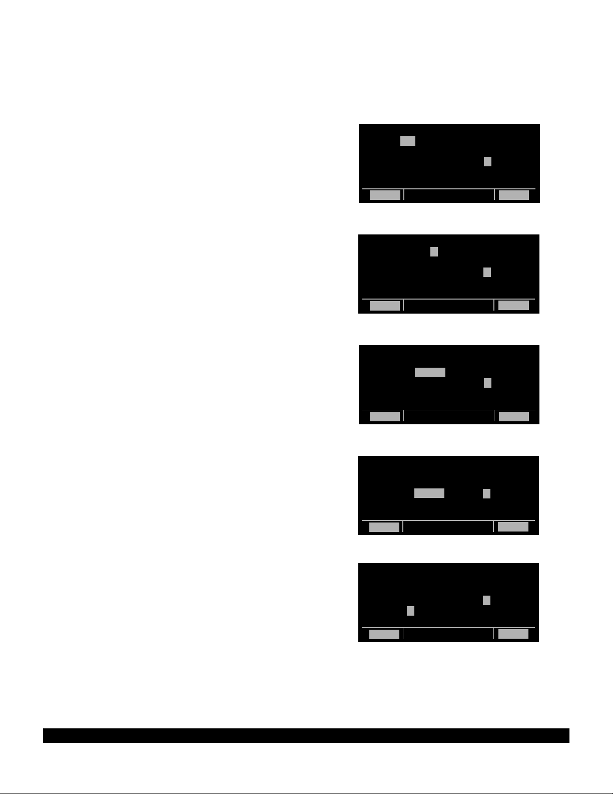
3-55
Rev 1
3.15 ALTITUDE ALERTING
If your aircraft does not already have an altitude alerting
capability you may wish to use the KLN 90B’s capability of
assisting you with altitude management during your flying.
Altitude alerting allows you to select a target altitude and it
then provides you with an aural alarm 1000 feet prior to
reaching the selected altitude, another aural alarm upon
reaching the selected altitude, and another aural alarm if
you deviate from the selected altitude.
NOTE: The altitude alerting function of the KLN 90B does
not meet FAR Part 91 for turbojet-powered civil airplanes.
To use the altitude alerting:
1. Press A. The Altitude page will be displayed on the
left with the cursor over the first two digits of the altimeter baro set field. The NAV 4 page will be displayed on
the right with the cursor over the first digit of the
selected altitude field (figure 3-175).
NOTE: The altimeter baro set units may be changed from
inches to millibars on the SET 7 page.
2. Use the left knobs to update the altimeter baro setting if
required. There are three cursor positions. Use the left
outer knob to move the cursor and the left inner knob to
change digits (figure 3-176). With the proper altimeter
baro setting, the indicated altitude (IND) on the right
should be the same as the aircraft’s actual altimeter.
NOTE: There may be some difference (less than 100 feet)
between the indicated altitude (IND) and the aircraft’s
actual altitude if the altitude input to the KLN 90B is from an
altitude encoder because these encoders only provide altitude in 100 foot increments.
3. Turn the left outer knob one step clockwise to position
the cursor over the ALERT: field (figure 3-177). If OFF
is displayed, turn the left inner knob to select ON (figure
3-178). When alerting is enabled, an arrow to the right
of ON points to the selected altitude on the right side of
the screen.
4. Select a warn altitude by using the left outer knob to
position the cursor over the WARN: field (figure 3-179).
Use the left inner knob to select the desired warn altitude. It is selectable in one hundred foot increments
from 200 feet up to 900 feet. Normally, you will use the
same warn altitude all the time so you only have to
enter this the first time you use altitude alerting. The
recommended warn altitude is 300 feet.
ALTITUDE |VNV INACTV
BARO:30.13"|
ALERT: OFF|IND 09000ft
|SEL:05500ft
|KMKC :-00nm
|ANGLE:-1.3^
CRSR enr-leg CRSR
Figure 3-175
ALTITUDE |VNV INACTV
BARO:30.09"|
ALERT: OFF|IND 09000ft
|SEL:05500ft
|KMKC :-00nm
|ANGLE:-1.3^
CRSR enr-leg CRSR
Figure 3-176
ALTITUDE |VNV INACTV
BARO:30.09"|
ALERT: OFF|IND 09000ft
|SEL:05500ft
|KMKC :-00nm
|ANGLE:-1.3^
CRSR enr-leg CRSR
Figure 3-177
ALTITUDE |VNV INACTV
|
BARO:30.09"|IND 09000ft
ALERT: ON =|SEL:05500ft
WARN:±300ft|KMKC :-00nm
|ANGLE:-1.5^
CRSR enr-leg CRSR
Figure 3-178
ALTITUDE |VNV INACTV
|
BARO:30.09"|IND 09000ft
ALERT: ON =|SEL:05500ft
WARN:±300ft|KMKC :-00nm
|ANGLE:-1.3^
CRSR enr-leg CRSR
Figure 3-179
Page 78

3-56
Rev 1
5. Enter the selected altitude one digit at a time in the SEL
field of the NAV 4 page by using the right outer knob to
position the cursor over the desired digit and the right
inner knob to change the digits until the entire selected
altitude is displayed (figure 3-180).
Only the selected altitude field (SEL) and the indicated altitude (IND) of the NAV 4 page are used for altitude alerting.
The rest of the NAV 4 page is used for vertical navigation
which is described in chapter 5.
6. Press A to return to the pages previously being displayed.
7. The aural alarm activates as follows:
• 1000 feet prior to reaching the selected altitude -
three short tones
• Upon reaching the selected altitude - two short
tones
• Deviating above or below the selected altitude by
more than the warn altitude - four short tones.
NOTE: Due to the resolution of the altitude input, it may be
necessary to descend slightly below or climb slightly above
the selected altitude before the two tones are activated
indicating that the selected altitude has been reached. This
selected altitude alert must be activated to arm the system
for providing the altitude deviation alert.
The KLN 90B can provide the aural alarm tones in either of
two ways: it may be connected to an audio input of an
audio amplifier contained in an audio panel so that the
aural alarm is heard through the aircraft’s speaker and
headphones. Or the KLN 90B may be interfaced with an
external tone generator installed in the aircraft.
In order to use altitude alerting, the KLN 90B must have an
altitude input. If the altitude input is from an altitude
encoder or from an air data computer not having a baro
altitude output, then it will be necessary for you to manually
input the proper altimeter setting in order to get accurate
alerting. Remember, the altitude coming from an encoder
is pressure altitude and must be corrected with the proper
altimeter setting to convert to actual altitude. This altimeter
setting is easily accomplished by entering the altimeter
baro setting on the Altitude page. Press A to display the
Altitude page. Use the left knobs to make the altimeter
baro setting. Press A again to return to the pages previously being displayed. It’s so easy you have no excuses
for not keeping the baro setting updated!
CAUTION: The altitude alerting feature will only be
accurate if the altimeter baro correction is kept
updated. If altitude alerting is used, it is a good idea to
update the altimeter baro set on the ALT page each
time you make a change to the aircraft’s altimeter setting.
ALTITUDE |VNV INACTV
|
BARO:30.09"|IND 09000ft
ALERT: ON =|SEL:04000ft
WARN:±300ft|KMKC :-00nm
|ANGLE:-0.0^
CRSR enr-leg CRSR
Figure 3-180
Page 79

3-57
Rev 1
The volume of the aural alarm tone is changeable on the
SET 9 page (figure 3-181). Press the left C to activate
the left cursor and use the left inner and outer knobs to
select a desired volume between 00 and 99. Increasing
numbers increases the volume.
NOTE: The altitude alerting and height above airport features can be disabled in the KLN 90B installation harness
so that these features are not selectable by the pilot. When
this has been done the SET 5, SET 9, and Altitude pages
display
OFF
and cannot be changed. In addition, the SET
5 and SET 9 pages display the following :
FEATURE DIS-
ABLED.
ALTITUDE |
ALERT |
VOLUME: |
|
02 |
|
SET 9
Figure 3-181
Page 80
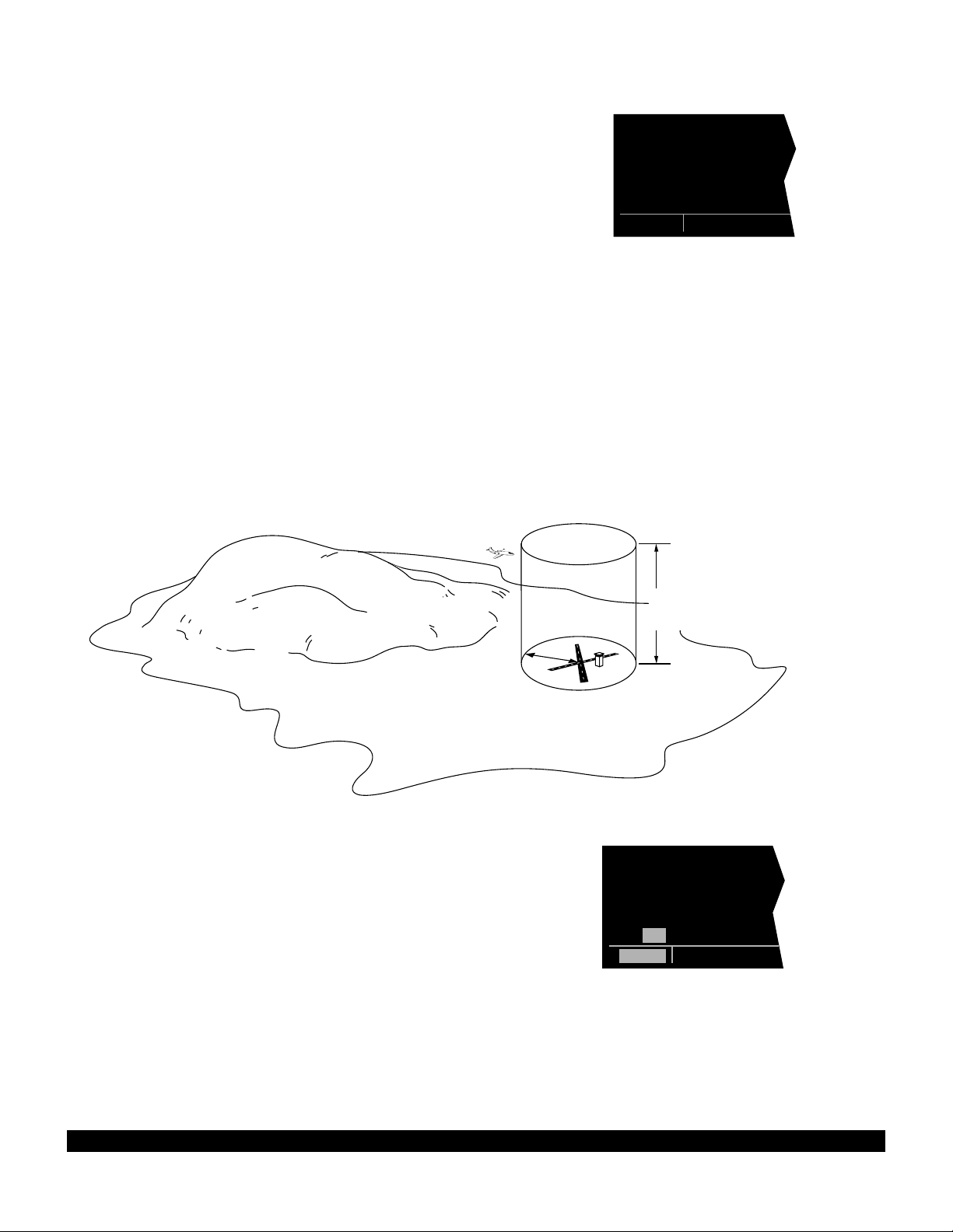
3-58
Rev 1
3.16 HEIGHT ABOVE AIRPORT ALERT
The height above airport alert feature can provide you a
means of knowing when you are at traffic pattern altitude
or when you are at a fixed height above the airport where
you might perform any repetitive duty.
The height above airport feature works as follows: You
enable/disable this feature and select an offset height on
the SET 5 page (figure 3-182). When the height above
airport alert is enabled, the KLN 90B creates a 5 nm
radius cylinder of airspace centered on an airport. This
airport is any airport that is a Direct To waypoint or is the
“TO” waypoint in the active flight plan. The height of the
cylinder above the airport is the offset height you select
on the SET 5 page. The KLN 90B adds this offset height
to the elevation stored in the database for the airport.
The KLN 90B compares the aircraft’s position relative to
the cylinder and notifies you with an aural alert when the
aircraft first penetrates the cylinder (figure 3-183). The
alert consists of a short tone, followed by a long tone, followed by a short tone.
HT ABOVE |
APT ALERT |
ON |
|
APT ELEV |
[ 800ft |
SET 5
Figure 3-182
5
NM
Airport elevation
plus selected offset height
Figure 3-183
HT ABOVE |
APT ALERT |
ON |
|
APT ELEV |
[ 800ft |
CRSR
Figure 3-184
To enable or disable the height above airport alert, press
the left C. Use the left outer knob to position the cursor
over the enable/disable field. Turn the left inner knob to
select ON or OFF as desired. To select the offset height,
use the left outer knob to position the cursor over the offset field (figure 3-184). Turn the left inner knob to select
an offset between 800 feet and 2000 feet. Press the left
C to turn the cursor off.
WARNING: The height above airport alert feature
does not serve the same function as a radar altimeter. It does not provide any warning about the aircraft’s actual height above the airport’s surrounding
terrain.
Page 81

The alert tone is provided in the same way as described
in section 3.15, “Altitude Alerting”. The volume is
adjustable on the SET 9 page.
In order to use the height above airport alert, an altitude
input must be provided to the KLN 90B. If the altitude
input to the KLN 90B is pressure altitude such as from an
altitude encoder or air data computer, then the altitude
must be corrected with the proper altimeter baro setting.
This is accomplished on the ALT page as described in
section 3.15, “Altitude Alerting.”
CAUTION: The height above airport alert feature will
only be accurate if the altimeter baro correction is
correct. If the height above airport alert feature is
enabled, it is a good idea to update the altimeter baro
set on the ALT page each time you make a change to
the aircraft’s altimeter setting.
NOTE: The altitude alerting and height above airport fea-
tures can be disabled in the KLN 90B installation harness
so that these features are not selectable by the pilot. When
this has been done the SET 5, SET 9, and Altitude pages
OFF
display
5 and SET 9 pages display the following :
ABLED.
and cannot be changed. In addition, the SET
FEATURE DIS-
3.17 REMOTE MOUNTED ANNUNCIATORS
The KLN 90B has outputs capable of driving two remote
annunciator lights: waypoint alert and message.
Although these annunciators are optional, it is desirable
to have them mounted in the pilot’s normal scan area so
that these annunciators are easily seen. A typical
annunciator is shown in figure 3-185; however, actual
annunciation abbreviations and configurations may be different.
In addition, there may be a NAV/GPS switch/annunciator
to switch a CDI or HSI navigation source between the
KLN 90B and a VOR/ILS system; a GPS APR
switch/annunciator which allows display and control of the
approach modes (see section 6.1; and a GPS CRS
switch/annunciator which allows changing between Leg
and OBS modes (see section 5.9.1).
The remote waypoint alert annunciator is on whenever
waypoint alerting is occurring. See sections 3.8.6 and
4.2.2.
The remote message annunciator is on whenever the
message prompt is on. See section 3.5.
WPT
MSG
Figure 3-185
3-59
Rev 1
Page 82

3-60
Rev 1
3.18 SAMPLE TRIP
Just to make sure you are ready to use the KLN 90B for
navigation, let’s go through a sample trip to illustrate
many of the features you have learned to use in this section of the Pilot’s Guide. Our trip will be from Adams field
(KLIT) in Little Rock, Arkansas to Mueller Municipal airport (KAUS) in Austin, Texas. The weather is perfect and
you decide to make the trip VFR and fly direct to Austin.
3.18.1 Pre-Departure
1. Apply power to the KLN 90B by pushing the
power/brightness knob to the “in” position.
2. When the screen warms up, adjust the brightness to
the desired level by rotating the power/brightness
knob.
3. Verify that the information on the Self Test page is correct, including the time and date. Enter the altimeter
baro setting. Position the cursor over APPROVE?
and press E to approve the Self Test page.
4. Read the Database page. Acknowledge the
Database page by pressing E.
5. A blank NAV 2 page is now displayed on the left side
on the screen. The APT 4 page for Adams field
(KLIT), which shows the communications frequencies,
is now displayed on the right side of the screen since
KLIT was the active waypoint when you last removed
power from the KLN 90B. The APT 4 page indicates
that the ATIS frequency is 125.65 MHz, the pre-taxi
clearance delivery frequency is 118.95 MHz, the
ground control frequency is 121.90 MHz, and the
tower frequency is 118.70 MHz. After listening to
ATIS, you contact clearance delivery for your clearance out of the Little Rock Class C airspace. Next,
you give ground control a call and receive your taxi
clearance.
6. By this time the KLN 90B has reached a NAV ready
status. You know this because the NAV 2 page is
now showing a valid present position, in this case 3.8
nautical miles on the 320 degree radial from Little
Rock (LIT) VOR.
7. Press D to bring up the Direct To page on the left
side. Use the two left knobs to enter the identifier of
Mueller Municipal airport (KAUS) by using the left
inner knob to select the characters and the left outer
knob to move the flashing part of the cursor to the
desired cursor location.
8. Press E to bring up the APT 1 waypoint page for
Mueller Municipal airport on the right side.
9. Press E again to approve the waypoint page. The
NAV 1 page is now displayed on the right side of the
screen while the NAV 2 page returns to the left side.
The NAV 1 page indicates it is 384 nautical miles to
Austin and that the bearing is 225 degrees. After
take-off, the NAV 1 page will also display groundspeed and estimated time enroute.
10.You now decide to view the Super NAV 1 page.
Rotate the left inner knob to select the NAV 1 page.
3.18.2 Enroute
1. You depart from runway 36 at Little Rock and are told
to “maintain runway heading”. After several radar vectors for traffic avoidance you are finally cleared on
course. The D-Bar indicates that the radar vectors
have taken you north of the original course and you
decide to proceed Direct To Austin from your present
position. To recenter the D-Bar, press D, and then
press E.
2. In order to determine the minimum enroute safe altitude (ESA) for the flight you view the NAV 3 page. It
indicates an ESA of 4300 feet for the trip and minimum safe altitude for your present position of 3400
feet.
3. After departure control has directed “squawk 1200,
frequency change approved”, you decide it would be a
good idea to obtain VFR flight following. To obtain the
frequency for Center, select the Other 2 page (OTH
2). It indicates that for your position, you should be
able to contact Memphis Center on 118.85 MHz.
4. You’ve only flown about 100 nautical miles, but you
begin wondering where you would go if an engine
suddenly started running rough. You decide to use
the KLN 90B to determine where the nearest airports
are from your present location. To view the nearest
airports press M, and then press E. The nearest
airport is Hope Municipal (M18) which is eight nautical
miles from your position on a bearing to the airport of
11 degrees. You now rotate the right inner knob to
view the other APT pages for Hope Municipal. You
learn, for example, that it is located in Hope,
Arkansas, and has two hard surface runways that are
each 5500 feet in length. By pulling the right inner
knob to the “out” position, you may now scan clockwise through the remaining eight airports in the nearest airport list.
5. For the majority of the enroute portion of the flight you
select, the Super NAV 5 page’s moving map display.
You do this by selecting NAV 5 on both sides of the
screen. Pressing the right C brings up the waypoint
display menu on the right side of the screen. You
then use the right knobs to select APT: ON so that
nearby airports are shown on the moving map display.
Page 83

3-61
Rev 1
While the display menu is displayed, select the track
up map orientation (TK) as well. Pressing the right C
again removes the menu from the screen. You select
the 30 nm range scale on the left side using the left
C and left knobs. You also decide to display ETE,
DTK, and TK on the left side of the map display by
using the left knobs.
6. Since it is a good idea to not rely on just one navigation source, you decide to cross check the KLN 90B
position against other equipment in the aircraft. The
NAV 2 page indicates you are presently located on the
Texarkana (TXK) VOR 68 degree radial at a distance
of 19 nautical miles. By tuning your Navigation
Receiver and DME to TXK, you are able to confirm
that this is the correct position.
3.18.3 Terminal Area
1. About 50 nautical miles from Austin’s Mueller airport
you start preparing for your arrival. Viewing the APT 4
page for KAUS you determine that the ATIS frequency is 119.20 MHz and tower is 121.00 MHz.
2. A few minutes later, the message prompt begins flashing. When you press M, the message page advises:
AIRSPACE ALERT - AUSTIN CL C - SEE KAUS
APT 4 PAGE BELOW 4600 FT. The Special Use
Airspace Alert feature has determined that you are
within 10 minutes of penetrating the Austin Class C
airspace. When you view the APT 4 page, you see
that the Class C airspace frequencies are sectorized.
You determine from the APT 4 page that the proper
frequency to use is 124.90 MHz since you are
Northeast of Austin and 124.90 MHz is the appropriate
frequency to use from 3 degrees to 170 degrees.
3. After you call Austin approach control for clearance
into the Class C airspace, you view the rest of the
APT pages for KAUS to determine the field elevation
and available runways. The first APT 3 page shows
you a runway diagram for the airport.
4. After landing, the KLN 90B is turned off either by
pulling the power/brightness switch to the “out” position or with the avionics master switch if one is
installed.
Page 84

3-62
Rev 1
THIS PAGE INTENTIONALLY LEFT BLANK
Page 85

4-1
Rev 1
This is the second of four chapters specifically dealing with
operating the KLN 90B. In this chapter you will learn to
create and use flight plans. A flight plan is an organized
listing of waypoints defining your route of flight.
You may feel that you learned all you need to know in
chapter 3 about operating the KLN 90B, since you can use
the Direct To operation to fly anywhere you want to go.
However, you would be selling yourself and the KLN 90B
short if you stop there. Using the unit’s flight plan capabilities provides more information and, in some respects,
reduces your enroute workload regardless of whether your
flying is done VFR or IFR. Other advantages of creating
flight plans are: (1) the entire route of flight for an upcoming trip can be created and stored prior to departure; and
(2) the routes for frequently made trips need to be created
just once and may then be recalled as required for later
use. Using the KLN 90B only for Direct To operation
would be like flying a retractable gear aircraft with the gear
down all the time — you’re just not getting the most out of
your equipment!
CHAPTER 4 - LEVEL 2 OPERATION
4.1 CREATING AND MODIFYING
FLIGHT PLANS
The following rules and considerations apply to KLN 90B
flight plans:
• The KLN 90B is capable of storing in its memory 25
flight plans plus an active flight plan.
• Each of the flight plans may contain up to 30 way-
points. These waypoints may consist of any combination of published waypoints from the database or user
created waypoints.
• The flight plans are numbered 0 through 25 (FPL 0,
FPL 1, FPL 2, ..., FPL 25).
• The active flight plan is always FPL 0. The standard
procedure is to create a flight plan in one of the flight
plans numbered as FPL 1, FPL 2, FPL 3,..., or FPL
25. When one of these numbered flight plans is activated, it becomes FPL 0, the active flight plan. This
Pilot’s Guide will refer to FPL 0 as the “active flight
plan” and FPL 1 through FPL 25 as the “numbered
flight plans.” If desired, a flight plan can be created
directly in the active flight plan. This avoids creating
the flight plan in a numbered flight plan and then having to activate it. The disadvantage is that if a numbered flight plan is subsequently made active, the one
programmed directly into FPL 0 will be lost.
• Modifications may be made to FPL 0 without affecting
the way it is stored as a numbered flight plan.
• Unless Direct To operation is being used, the active
flight plan (FPL 0) must contain at least two waypoints. Otherwise, the KLN 90B system will be
flagged.
Page 86

4.1.1 Creating A Flight Plan
A flight plan for a flight from Lakefront airport in New
Orleans, LA. to St. Petersburg/Clearwater, FL.
International airport will be used as an example of how to
create a flight plan. The waypoints making up the flight
plan are: KNEW(Lakefront airport), GPT(Gulfport VOR),
SJI(Semmes VOR), CEW(Crestview VOR),MAI
(Marianna VOR), TLH(Tallahassee VOR), CTY(Cross
City VOR), and KPIE(St. Petersburg/Clearwater
International airport. To create the flight plan:
1.Rotate the left outer knob to select the flight plan
(FPL) type pages (figure 4-1).
2.Turn the left inner knob to select a flight plan page
(preferably other than FPL 0) which does not contain
a flight plan (figure 4-2). If all of the flight plan pages
contain flight plans, refer to section 4.1.5, “Deleting
Flight Plans.”
3.Press the left
left page (figure 4-3).
Cto turn on the cursor function for the
NOTE: The KLN 90B flight plan operation is designed so
that the first waypoint in the flight plan should always be
the departure point. Remember to enter the “K”, “P”, or
“C” prefix for certain airports in the United States, Alaska,
or Canada. See section 2.3, “USE OF ICAO IDENTIFIERS.”
4.Use the left inner knob to select the first character of
the departure waypoint identifier (figure 4-4).
5.Turn the left outer knob one step clockwise to move
the flashing portion of the cursor over the second
character position, and then use the left inner knob to
select the desired character.
USE? INVRT?|
1:KMKC |
2:BUM |
3:OSW |
4:TUL |
6:KRVS |
FPL 8
Figure 4-1
LOAD FPL 0?|
1: |
|
|
|
|
CRSR
Figure 4-3
LOAD INVRT?|
1:KNEW |
2: |
|
|
|
CRSR
Figure 4-5
LOAD FPL 0?|
1: |
|
|
|
|
FPL 4
Figure 4-2
LOAD INVRT?|
1:K |
2: |
|
|
|
CRSR
Figure 4-4
6.Use the above procedure to select the entire identifier
for the first waypoint (figure 4-5).
7.Press E. A waypoint page for the identifier just
entered will be displayed on the right side (figure 4-6).
If a mistake was made and the wrong waypoint identifier was entered, press @and begin again. If a mistake was not made but the waypoint identifier just
entered isn’t in the database, a page allowing creation
of a user defined waypoint will appear on the right
side. Refer to section 5.4, “USER-DEFINED WAYPOINTS”, for instruction on how to define a user created waypoint.
8.Press Eagain to approve the waypoint page being
displayed. The cursor will move to the second
waypoint position (figure 4-7).
NOTE: A small number of waypoints are stored in the
database as “fly-over” waypoints. These waypoints are
associated with SID/STAR procedures. “Fly-over” means
USE? INVRT?| KNEW
1:KNEW |LAKEFRONT
2: |
| CL C
|N 30^02.53'
|W 90^01.69'
CRSR|enr-leg ent|APT 1
Figure 4-6
USE? INVRT?|
1:KNEW |
2: |
|
|
|
CRSR
Figure 4-7
4-2
Rev 1
Page 87

that, for some reason, the governing agencies have
decided that it is important to fly directly over the
waypoint instead of being able to “cut the corner” by
using turn anticipation (see section 4.2.2). In these cases
the KLN 90B will present a waypoint type identification
page (Figure 4-7a). Simply select the way in which the
waypoint is intended to be used with the left outer knob
E
and press
. If the SID/STAR choice is selected, the
KLN 90B will disable turn anticipation for that waypoint (if
previously enabled). The KLN 90B will enable turn anticipation after the waypoint has been passed (if turn anticipation was previously enabled). If en route is selected,
then normal turn anticipation occurs.
SWR | SWR D
TYPE WPT |SQUAW
|VALLEY L
1 EN ROUTE?|113.20 16^E
2 SID/STAR?|N 39^10.82'
|W120^16.18'
CRSR|enr-leg ent|VOR
Figure 4-7a
9.Use the same procedure to enter the rest of the way-
points in the flight plan (figure 4-8). If the flight plan
consists of five or more waypoints, the waypoints will
automatically scroll as necessary to allow entry of the
next waypoint.
10.When all of the waypoints have been entered in the
flight plan, the left outer knob may be rotated to move
the cursor up and down and manually “scroll” through
the waypoints making up this flight plan. This is useful
if the flight plan contains six or more waypoints since
not all of the waypoints can be displayed at one time.
When the left outer knob is rotated to the full counterclockwise position, the cursor will be positioned over
USE?(figure 4-9). If there are more than five waypoints in the flight plan, the first four waypoints will
then be displayed followed by the last waypoint in the
flight plan. Rotate the left outer knob to move the cursor and manually scroll to see the missing intermediate waypoints.
11.Press the left Cto turn off the left cursor function.
Additional flight plans may now be created in the
same manner.
4.1.2 Activating A Numbered Flight Plan
To activate one of the previously created numbered flight
plans:
1.Use the left outer knob to select the flight plan (FPL)
type pages.
2.Rotate the left inner knob to select the desired flight
plan (figure 4-10).
4:CEW |
5:MAI |
6:TLH |
7:CTY |
8:KPIE |
9: |
CRSR
Figure 4-8
USE? INVRT?|
1:KNEW |
2:GPT |
3:SJI |
4:CEW |
8:KPIE |
CRSR
Figure 4-9
USE? INVRT?|
1:KNEW |
2:GPT |
3:SJI |
4:CEW |
8:KPIE |
FPL 4
Figure 4-10
3.Press the left Cto enable the left cursor function.
The cursor will appear over USE?(figure 4-11). If you
haven’t left the numbered flight plan page since creating this flight plan, rotate the left outer knob all the way
counterclockwise to position the cursor over USE?
USE? INVRT?|
1:KNEW |
2:GPT |
3:SJI |
4:CEW |
8:KPIE |
CRSR
Figure 4-11
4-3
Rev 1
Page 88

4-4
Rev 1
4. Press E to activate the flight plan in the order shown
(figure 4-12). To activate the flight plan in inverse
order (first waypoint becomes last and last waypoint
becomes first), rotate the left outer knob one step
clockwise to position the cursor over USE? INVRT?
before pressing E (figure 4-13).
5. The selected flight plan is now displayed as FPL 0, the
active flight plan. Any changes made to FPL 0 will not
affect how this flight plan is stored as the numbered
flight plan.
4.1.3 Adding A Waypoint To A Flight Plan
A waypoint may be added to any flight plan containing
fewer than 30 waypoints. To add a waypoint to a flight
plan:
1. Press the left C to enable the left cursor function if it
is not on already (figure 4-14).
2. Rotate the left outer knob as necessary to position the
cursor over the waypoint identifier which you desire to
follow the waypoint being added. Another way to
think of this is to position the cursor over the location
in the flight plan you wish the new waypoint to be
added. For example, if SJI is presently the third
waypoint in the flight plan and you wish to insert
BUGLE intersection in the number three position in
front of SJI, move the cursor over SJI (figure 4-15).
3. Use the left inner knob to enter the first character of
the waypoint being inserted. As you begin to turn the
knob, the existing waypoint in this position automatically jumps down to the next position. In this case,
SJI automatically moves to waypoint four (figure 4-
16).
4. Use the left outer and inner knobs in the normal manner to complete entering the waypoint identifier (figure
4-17).
5. Press E to display the waypoint page on the right
side for the identifier just entered.
6. Press E again to approve the waypoint page
(figure 4-18).
7. Press the left C to turn off the left cursor function.
|
1:KNEW |
2:GPT |
3:SJI |
4:CEW |
8:KPIE |
CRSR
Figure 4-14
|
1:KNEW |
2:GPT |
3:SJI |
4:CEW |
8:KPIE |
CRSR
Figure 4-15
|
1:KNEW |
2:GPT |
3:B |
4:SJI |
9:KPIE |
CRSR
Figure 4-16
|
1:KNEW |
2:GPT |
3:BUGLE |
4:SJI |
9:KPIE |
CRSR
Figure 4-17
|
1:KNEW |
2:GPT |
3:BUGLE |
4:SJI |
9:KPIE |
CRSR
Figure 4-18
|
1:KNEW |
2:GPT |
3:SJI |
4:CEW |
8:KPIE |
FPL 0
Figure 4-12
USE? INVRT?|
1:KNEW |
2:GPT |
3:SJI |
4:CEW |
8:KPIE |
CRSR
Figure 4-13
Page 89

4-5
Rev 1
4.1.4 Deleting A Waypoint From A Flight Plan
To delete a waypoint from a flight plan:
1. Press the left C to enable the left cursor function if it
is not on already.
2. Rotate the left outer knob as necessary to position the
cursor over the waypoint to be deleted (figure 4-19).
3. Press @. The letters DEL (delete) will appear to the
left of the identifier and a question mark will appear to
the right of the identifier (figure 4-20). If a mistake was
made and you do not wish to delete this waypoint,
press @.
4. Press E and the waypoint will be deleted from the
flight plan. The other waypoints in the flight plan will
be correctly repositioned (figure 4-21).
5. Press the left C to turn off the left cursor function.
4.1.5 Deleting Flight Plans
To delete a flight plan which is no longer required:
1. Display the flight plan (FPL 0, FPL 1, FPL 2,..., or FPL
25) which is to be cleared (figure 4-22).
2. Make sure the left cursor function is turned off. If the
left cursor is on, press the left C to turn it off.
3. Press @. The words DELETE FPL? will appear at
the top of the page (figure 4-23). If a mistake was
made and you do not wish to clear this flight plan,
press @.
4. Press E to clear the flight plan (figure 4-24).
|
1:KNEW |
2:GPT |
3:BUGLE |
4:SJI |
9:KPIE |
CRSR
Figure 4-19
USE? INVRT?|
1:KNEW |
2:GPT |
DEL BUGLE? |
4:SJI |
9:KPIE |
CRSR
Figure 4-20
|
1:KNEW |
2:GPT |
3:SJI |
4:CEW |
8:KPIE |
CRSR
Figure 4-21
USE? INVRT?|
1:KMKC |
2:BUM |
3:OSW |
4:TUL |
6:KRVS |
FPL 8
Figure 4-22
DELETE FPL?|
1:KMKC |
2:BUM |
3:OSW |
4:TUL |
6:KRVS |
CRSR
Figure 4-23
LOAD FPL 0?|
1: |
|
|
|
|
FPL 8
Figure 4-24
Page 90

4.1.6 Storing FPL 0 As A Numbered Flight Plan
The active flight plan may be loaded into a numbered
flight plan so that it can be recalled for later use. This
may be desirable, for example, if the active flight plan was
originally created on the FPL 0 page and not as a numbered flight plan. To store the active flight plan as a numbered flight plan:
1.Select a numbered flight plan page which does not
contain any waypoints (figure 4-25). If none exist, use
the procedure described in n 4.1.5, “Deleting
Flight Plans,” to clear a flight plan which is no longer
required.
2.Press the left Cto turn on the left cursor function
with the cursor over the blank first waypoint position
(figure 4-26).
3.Rotate the left outer knob one step counterclockwise
to position the cursor over LOAD FPL 0? (figure 4-
27).
4.Press Eto load the active flight plan into this numbered flight plan (figure 4-28).
LOAD FPL 0?|
1: |
|
|
|
|
FPL 7
Figure 4-25
LOAD FPL 0?|
1: |
|
|
|
|
CRSR
Figure 4-26
USE? INVRT?|
1:KHOU |
2:DAS |
3:LFK |
4:BEKEN |
5:KSHV |
FPL 7
LOAD FPL 0?|
1: |
|
|
|
|
CRSR
Figure 4-27
Figure 4-28
4-6
Rev 1
Page 91

4.2 OPERATING FROM THE ACTIVE FLIGHT PLAN
4.2.1 General Procedures
Everything you have learned in this Pilot’s Guide thus far
is applicable to using the KLN 90B for flight plan operation. The following rules and considerations apply for
flight plan operation while the KLN 90B is in the Leg
mode:
•Although any of the KLN 90B pages may be utilized
while operating along a flight plan, common page
selections are the FPL 0 page on the left side while
simultaneously displaying one of three Distance/Time
pages (D/T 1, D/T 2, D/T 3) or the NAV 5 page (navigation graphics) on the right side. The information
contained on the Distance/Time pages is explained
later, beginning in section 4.2.5, “The Distance/Time
Pages”. The Super NAV 5 page is especially useful
for flight plan operation. It provides you with a visual
orientation of your position in the active flight plan and
displays the alphanumeric identifiers of the flight plan
waypoints. Of course the other four Navigation pages
may also be used extensively. Now would be a good
time to take a couple of minutes and review the NAV 5
and Super NAV 5 pages as they relate to flight plan
operation (see sections 3.9.6 and 3.9.7).
; 1:KNEW |
< 2:GPT |
3:SJI |
4:CEW |
5:MAI |
8:KPIE |
FPL 0
Figure 4-29
•Always verify that you are viewing the active flight plan
page (FPL 0) and not one of the other numbered flight
plan pages.
•The active leg of the flight plan is designated with a ∑
symbol. A leg is defined as the course line between a
pair of waypoints (a “from” waypoint and a “to”
waypoint). The head of the arrow is positioned to the
left of and points to the active “to” waypoint. In figure
4-29, GPTis the “to” waypoint. The tail of the ∑symbol is positioned to the left of the “from” waypoint.
KNEWis the “from” waypoint in figure 4-29. The ∑
symbol is not displayed unless the KLN 90B is actually
receiving navigation signals suitable for navigation.
(Note: If the unit is in the take-home mode, it has
been “tricked” into thinking it is receiving signals and
therefore the ∑symbol can be displayed). Also, the ∑
symbol will not be displayed if Direct To navigation is
occurring. If in doubt as to whether or not Direct To
operation is occurring, view the NAV 1 page. If the top
line shows the Æsymbol (figure 4-30) instead of a
“from” waypoint (figure 4-31), then Direct To navigation
is occurring. If it is desired to cancel the Direct To
operation and operate from the active flight plan; press
D, then press @, then press E.
•As flight plan waypoints are reached, the active leg
symbol automatically orients itself on the next leg.
$=KHOU |
+++++Ê+++++|
DIS 278nm|
GS 182kt|
ETE 1:32|
BRG 264^|
NAV 1
Figure 4-30
KNEW =GPT |
+++++Ê+++++|
DIS 52.4nm|
GS 182kt|
ETE :18|
BRG 065^|
NAV 1
Figure 4-31
4-7
Rev 1
Page 92
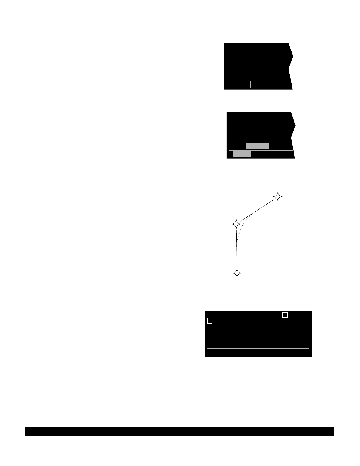
4-8
Rev 1
• If the flight plan contains more waypoints than can be
displayed on the screen at one time, the page will
automatically scroll as progress is made along the
flight plan so that the active leg is always displayed
(figure 4-32).
• The last waypoint in the flight plan is always displayed
at the bottom of the FPL 0 page, even if all of the waypoints in the flight plan can’t be displayed on the page
at one time. To view intermediate waypoints, turn the
left cursor function on and use the left outer knob to
manually scroll through all of the waypoints, as
desired. If scrolling is performed all the way to the end
of the flight plan, a blank waypoint position will exist so
that a waypoint may be added to the end of the flight
plan (figure 4-33).
4.2.2 Turn Anticipation And Waypoint Alerting
Prior to reaching a waypoint in the active flight plan, the
KLN 90B will provide navigation along a curved path segment to ensure a smooth transition between two adjacent
legs in the flight plan. That is, the CDI or HSI left/right
deviation will be referenced to the dashed line in figure 4-
34. This feature is called turn anticipation. The transition
course is based upon the aircraft’s actual groundspeed
and the amount of course angle change between the two
legs. The KLN 90B automatically sequences to the next
leg after passing the midpoint in the transition segment.
Approximately 20 seconds prior to the beginning of turn
anticipation, the arrow preceding the active waypoint
identifier will begin flashing on the FPL 0 page and on any
Navigation page, Distance/Time page, or waypoint page
displaying the active waypoint identifier (figure 4-35). On
the Super NAV 5 page, the entire active waypoint identifier will start to flash. This is called “waypoint alerting”. If
an external waypoint alert annunciator is mounted in the
aircraft, this annunciator will begin flashing at the same
time.
To utilize the turn anticipation feature, start the turn transitioning to the next leg in the flight plan at the very
beginning of turn anticipation. This occurs when the
external waypoint alert annunciator or the active waypoint
identifier on the Super NAV 5 page stops flashing and
goes on steady. At this time the KLN 90B will notify you
with a message on the Message page of the new desired
track to select on your HSI or CDI.
ADJ NAV IND CRS TO 123°
A message will not be given if the change in desired track
(course change) is less than 5°. In addition, a message
will not be given if the KLN 90B is interfaced with an EHSI
or HSI having a course pointer that is automatically
slewed to the correct desired track.
3:SJI |
; 4:CEW |
< 5:MAI |
6:TLH |
7:CTY |
8:KPIE |
FPL 0
Figure 4-32
; 4:CEW |
< 5:MAI |
6:TLH |
7:CTY |
8:KPIE |
9: |
CRSR
Figure 4-33
WPT 1
WPT 2
WPT 3
Figure 4-34
5
; 1:KNEW |KNEW =GPT
= 2:GPT |+++++Ê+++++
3:SJI |DIS 0.4nm
4:CEW |GS 182kt
5:MAI |ETE :00
8:KPIE |BRG 065^
FPL 0 enr-leg NAV 1
Figure 4-35
Page 93

4-9
Rev 1
The desired track (DTK) displayed on the NAV 3 page
also changes to the value for the next leg at the beginning
of turn anticipation. Turn anticipation becomes inactive
when transition to the next leg has been made.
In some installtions the KLN 90B can “read” the selected
course set on external CDIs or HSIs. In these installations
the KLN 90B will flash the value of desired track (DTK) on
both the NAV 3 and Super NAV 5 pages when the
desired track and the selected course differ by more than
10°. Set the selected course to match the desired track.
This will make sure that the orientation “picture” is always
correct.
If desired, turn anticipation may be disabled (or enabled)
on the Setup 6 page (SET 6) using the left C and the
left inner knob to select between DISABLE or ENABLE
(figure 4-36). If turn anticipation is disabled, navigation is
provided all the way to the waypoint, and waypoint alerting occurs approximately 36 seconds prior to actually
reaching the waypoint.
Figure 4-36
TURN |
ANTICIPATE |
|
ENABLE |
|
|
SET 6
Page 94

4.2.3 Viewing The Waypoint Pages For The Active Flight Plan Waypoints
The waypoint pages(s) for each of the waypoints in the
active flight plan may be easily displayed by selecting the
Active Waypoint page type (ACT) on the right side.
When the ACT page type is first selected, the waypoint
page for the active waypoint will be displayed (figure 4-
37). The location of the waypoint in the flight plan
(waypoint 1, waypoint 2, etc.) is annunciated with a number to the left of the identifier. In addition, an arrow to the
left of the waypoint number designates the active
waypoint. The letter to the far right of the identifier designates the type of waypoint: A= airport, V= VOR, N=
NDB, I= intersection, S= supplemental or T= terminal
(for details on terminal waypoints see section 6.1.2). For
VORs having DME capability, the letter D is displayed
between the VOR identifier and the V. To view the other
waypoints in the flight plan, pull the right inner knob to the
“out” position and turn it to view each of the waypoints in
the order they are contained in the flight plan (figure 4-
38). For airport waypoints, the right inner knob may be
pushed back to the “in” position and rotated to display any
of the eight airport pages (figure 4-39). Pulling the knob
back out will allow further scanning of the waypoint pages
in the active flight plan.
4.2.4 Combining Direct To And Flight Plan Operation
It is very common when using flight plan operation to use
the Direct To function to proceed directly to a waypoint
which exists in the flight plan. For example, after takeoff it
is common to receive radar vectors in the terminal area
and then be given a clearance direct to the first point in
the flight plan that was filed. The KLN 90B makes this
kind of operation very easy to accomplish. Whenever
you do a Direct To operation to a waypoint which is in the
active flight Plan (FPL 0), the system will provide navigation to the waypoint and then automatically resume navigation along the flight plan when the Direct To waypoint is
reached. Waypoints which exist prior to the Direct To
waypoint in the active flight plan are bypassed. Of
course, the active flight plan will never be resumed if the
Direct To operation is to a waypoint which is not in the
active flight plan.
; 1:KNEW |= 2 GPT D V
< 2:GPT |GULFPORT
3:SJI | L
4:CEW |109.00 2^E
5:MAI |N 30^24.40'
8:KPIE |W 89^04.60'
FPL 0|enr-leg |ACT
Figure 4-37
; 1:KNEW | 8 KPIE A
< 2:GPT |ST PETES-
3:SJI |CLERWTR
4:CEW |CL B
5:MAI |N 27^54.63'
8:KPIE |W 82^41.26'
FPL 0 enr-leg ACT 1
Figure 4-38
; 1:KNEW | 8 KPIE A
< 2:GPT |
3:SJI |17L/35R L
4:CEW | 8500' HRD
5:MAI |04 /22 L
8:KPIE | 5500' HRD
FPL 0 enr-leg ACT[3
Figure 4-39
Any of the several methods previously described for initiating Direct To operation may be used, although the one
below is the easiest for this application. The procedure
below takes advantage of rule number 1 described in
section 3.8.
4-10
Rev 1
Page 95

1.Select the FPL 0 page of the left side.
2.Press the left Cand then use the left outer knob to
position the cursor over the desired waypoint (figure 4-
40).
3.Press D. The waypoint page for the selected
waypoint in FPL 0 will be displayed on the right side
(figure 4-41).
; 1:KNEW |= 2 GPT D V
< 2:GPT |GULFPORT
3:SJI | L
4:CEW |109.00 2^E
5:MAI |N 30^24.40'
8:KPIE |W 89^04.60'
CRSR enr-leg ACT
Figure 4-40
4.Press Eto approve the waypoint page. The Direct
To waypoint identifier in the active flight plan will now
be preceded by just an arrow (figure 4-42). The ∑
symbol is not displayed since there is no “from”
waypoint in the flight plan.
An alternative method is to use the Super NAV 5 page to
select the direct to waypoint. This is done by pulling out
on the right inner knob. With the inner knob out, it is possible to scan through the waypoints of the active flight
plan as described in section 3.9.7. When the desired
waypoint is highlighted, press Dand then E.
If for some reason it is desired to cancel the Direct To
operation prior to reaching the Direct To waypoint in order
to proceed along the flight plan leg, press D, then press
@, and then press E.
4.2.5 The Distance/Time Pages
As stated earlier, it is common to use the Distance/Time
pages in conjunction with flight plan operation. The
Distance/Time pages are specially designed to be most
useful when the active flight plan page (FPL 0) is displayed simultaneously on the left side.
4.2.6 The Distance/Time 1 Page (D/T 1)
When the FPL 0 page is displayed on the left side and the
D/T 1 page is displayed on the right side, the distance
(DIS) and estimated time enroute (ETE) are displayed for
each of the active flight plan waypoints (figure 4-43). The
distance displayed is the cumulative distance from the aircraft’s present position to each waypoint along the flight
plan route. The ETE is displayed in hours:minutes. If
Direct To operation is occurring to a waypoint that is not
in the active flight plan, then the D/T 1 page is blank when
the FPL 0 page is displayed on the left (figure 4-44).
If a numbered flight plan page (FPL 1 though FPL 25) is
displayed on the left side, the distances displayed are
from the first waypoint in the flight plan and have nothing
to do with the aircraft’s present position. No ETEs are
then shown (figure 4-45).
DIRECT TO: | SJI D
< 2:GPT |SEMMES
SJI |17L/35R L H
4:CEW |115.30 5^E
5:MAI |N 30^43.55'
8:KPIE |W 88^21.56'
CRSR enr-leg ent VOR
Figure 4-41
1:KNEW | $=SJI
2:GPT |+++++Ê+++++
= 3:SJI |DIS 90.4nm
4:CEW |GS 180kt
5:MAI |ETE :30
8:KPIE |BRG 062^
FPL 0 enr-leg NAV 1
Figure 4-42
; 1:KNEW |DIS ETE
< 2:GPT | 34 :11
3:SJI | 76 :25
4:CEW |163 :54
5:MAI |243 1:21
8:KPIE |477 2:39
FPL 0 enr-leg D/T 1
Figure 4-43
|DIS ETE
1:KNEW |
2:GPT |
3:SJI |
4:CEW |
8:KPIE |
FPL 0 enr-leg D/T 1
Figure 4-44
USE? INVRT?|DIS ETE
1:KMKC |
2:BUM | 51
3:OSW |126
4:TUL |190
7:KDAL |432
FPL 6 enr-leg D/T 1
Figure 4-45
5
4-11
Rev 1
Page 96

If a non-flight plan page is displayed on the left, the format
of the D/T 1 page changes to display just the distance
and ETE for the active waypoint and for the last waypoint
in the flight plan (figure 4-46).
4.2.7 The Distance/Time 2 Page (D/T 2)
When the FPL 0 page is displayed on the left side and the
D/T 2 page is displayed on the right side, the distance
and estimated time of arrival are displayed for each of the
active flight plan waypoints (figure 4-47). The distances
are as described for the D/T 1 page. The time zone associated with the estimated time of arrival is annunciated at
the top right of the D/T 2 page. The time zone may be
changed by enabling the right cursor function to bring the
cursor over the time zone, and then turning the right inner
knob to select the desired time zone (figure 4-48).
Changing the time zone on the D/T 2 page changes the
time zone on other pages where time is displayed.
KNEW =GPT | = 2 GPT
+++++Ê+++++|DIS 34NM
DIS 34.2nm|ETE :11
GS 180kt| 8 KPIE
ETE :11|DIS 477NM
BRG 064^|ETE 2:39
NAV 1 enr-leg D/T 1
Figure 4-46
; 1:KNEW |DIS CST
< 2:GPT | 34 09:23
3:SJI | 76 09:37
4:CEW |163 10:06
5:MAI |243 10:33
8:KPIE |477 11:51
FPL 0 enr-leg D/T 2
Figure 4-47
If a numbered flight plan page other than FPL 0 is displayed on the left side, no estimated times of arrival are
displayed (figure 4-49).
If a non-flight plan page is displayed on the left side, the
format of the D/T 2 page changes to display just the distance and estimated time of arrival for the active waypoint
and for the last waypoint in the flight plan (figure 4-50).
4.2.8 The Distance/Time 3 Page (D/T 3)
When any flight plan page is displayed on the left side
and the D/T 3 page is displayed on the right side, the distance and desired track (DTK) are displayed (figure 4-51).
The distances are as described for the D/T 1 page. The
desired track is the great circle course between two waypoints. You should view the diagram in Appendix A if you
are unfamiliar with this term.
If a non-flight plan page is displayed on the left side, the
format of the D/T 3 page changes to display just the distance and desired track for the active waypoint and for
the next waypoint in the flight plan
this is different than for the D/T 1 and D/T 2 pages.
(figure 4-52). Note that
; 1:KNEW |DIS UTC
< 2:GPT | 34 15:23
3:SJI | 76 15:37
4:CEW |163 16:06
5:MAI |243 16:33
8:KPIE |477 17:51
FPL 0 enr-leg CRSR
Figure 4-48
USE? INVRT?|DIS CST
1:KMKC |
2:BUM | 51
3:OSW |126
4:TUL |190
7:KDAL |432
FPL 7 enr-leg D/T 2
Figure 4-49
KNEW =GPT | = 2 GPT
+++++Ê+++++|DIS 34NM
DIS 34.2nm| 15:23UTC
GS 180kt| 8 KPIE
ETE :11|DIS 477NM
BRG 064^| 17:51UTC
NAV 1 enr-leg D/T 2
Figure 4-50
; 1:KNEW |DIS DTK
< 2:GPT | 34 063^
3:SJI | 76 061^
4:CEW |163 085^
5:MAI |243 092^
8:KPIE |477 172^
FPL 0 enr-leg D/T 3
Figure 4-51
KNEW =GPT | = 2 GPT
+++++Ê+++++|DIS 34NM
DIS 34.2nm|DTK 064^
GS 180kt| 3 SJI
ETE :11|DIS 76NM
BRG 064^|DTK 061^
NAV 1 enr-leg D/T 3
Figure 4-52
4-12
Rev 1
Page 97

4-13
Rev 1
4.2.9 The Distance/Time 4 Page (D/T 4)
The format of the D/T 4 page does not change. It displays on a single page the pertinent times for the flight
regardless of what is displayed on the left page and
regardless of whether flight plan or Direct To operation is
occurring (figure 4-53). The information displayed on the
D/T 4 page is the following:
• The destination waypoint.
• The selected time zone. The time zone may be
changed by pressing the right C and using the right
inner knob to select the desired time zone.
• DEP - The departure time. There are two definitions of
departure time depending on what has been selected
on the Setup 4 page (SET 4 - see figure 4-54). If the
SET 4 page displays RUN WHEN
GS > 30KT, then the departure time is that time when
the groundspeed first reached 30 knots. If instead,
the SET 4 page displays RUN WHEN POWER IS ON,
then the departure time is the time when power was
applied to the KLN 90B. The SET 4 page may be
changed by pressing the left C while the SET 4
page is displayed on the left side and then rotating the
left inner knob. Press the left C again to turn the left
cursor function off.
• TIME - The present time. The time may be reset on
the Self Test page at system turn-on or on the SET 2
page.
• ETA - The estimated time of arrival at the destination
waypoint.
• FLT - The flight time. If RUN WHEN GS > 30 KT is
selected on the SET 4 page, then flight time is the
amount of time that the aircraft’s groundspeed has
been above 30 knots. Normally, this will be the time
since takeoff. However, time spent at groundspeeds
less than 30 knots such as intermediate stops without
shutting down power or helicopter hovering is not
counted as flight time.
If the present position flags (NAV flag) after being valid
in the NAV mode, the flight timer continues to run if
the groundspeed was more than 30 knots immediately
before the flag.
If RUN WHEN POWER IS ON is selected on the SET
4 page, then flight time is the time since power on.
• ETE - Estimated time enroute to the destination
waypoint.
| KPIE UTC
|DEP 15:02
|TIME 15:12
|ETA 17:51
|FLT :10
|ETE 2:39
D/T 4
Figure 4-53
FLIGHT |
TIMER |
OPERATION |
|
RUN WHEN |
GS > 30kt |
SET 4
Figure 4-54
Page 98

4-14
Rev 1
THIS PAGE INTENTIONALLY LEFT BLANK
Page 99
4-15
4.3 SAMPLE TRIP
Let’s use a sample trip to illustrate some of the KLN 90B’s flight plan features you learned to use in this section of the
Pilot’s Guide. The flight will be from Lakefront airport in New Orleans, LA. (KNEW) to St. Petersburg/Clearwater, FL.
international airport (KPIE). You decide to fly mostly an inland route rather than following the coast to avoid the many
restricted areas and MOAs and also to avoid thunderstorms which are occurring off the coast around Panama City (figure
4-55). The pages viewed in this scenario assume that the KLN 90B is driving an external HSI or CDI. If your KLN 90B
installation is not interfaced with an external HSI or CDI, then your page selection would have more emphasis on the
NAV 1 and Super NAV 1 pages than presented here.
TRI COUNTY
275 BKK
CORKY
(AAS)
19
29
V 198
DEFUN
2000
D30
2
GLEET
J-2
80
CHEWS
D
21
272°
MARIANNA
FLA 113
0
18
9
27
109°
288°
V 198
D
17
J-2
41
D24
12
2000
MAUNA
QUILL
QUINCY
FLA
222
12
D
114.0 MAI
D
MARIANNA
117.5 TLH
D
TALLAHASSEE
SNEAD
0
18
9
27
PANAMA
CITY FLA
288°
V 7-29
23
53
2000
53 TO CILLA
V 7-295
2000
90
312°
D37
14
D
CODYS
CILLA
0
18
9
27
0
18
9
27
112.0 CTY
D
CROSS CITY
170°
V 198
103
19
3000 1200T
X
D
CEDDI
18
2000
8
ELTOR
D58
26
ENDED
D
NEW PORT
RICHEY FLA
0
18
9
27
349°
ST PETERSBURG
CLEARWATER
116.4 PIE
D
ST PETERSBURG
GULF OF MEXICO
0
18
9
27
113.2 MSY
D
NEW ORLEANS
V 20
V 114
61
1800
064°
079°
NEW ORLEANS
LA Lakefront
25
5000
D
4
X
12
SLIDD
SNAKI
245°
8
D20
GULFPORT
MISS
CLERY
12
D
0
18
9
27
V-20
061°
2000
27
42
BUGLE
15
238°
0
18
9
27
109.0 GPT
D
GULFPORT
115.3 SJI
D
SEMMES
081°
GULF OF MEXICO
0
18
9
27
29
3000
D
V 241
87
LOXLY
D36
7
BRATT
V 198-241
20
3000
PENSI
J-2
D31
24
263°
7
D
BAKOS
RESTRICTED
AIRSPACE
9
D
088°
115.9 CEW
D
CRESTVIEW
GULF OF MEXICO
Rev 0
Page 100

4.3.1 Pre-Departure
1.After turn-on and approval of the Self Test and
Database pages, the APT 4 page (airport communication frequencies) for KNEWis displayed on the right
side of the screen. Viewing the APT 4 page, you set
up the COMMs for ATIS, Clearance Delivery, Ground,
and Tower.
2.You create the flight plan on the FPL 4 page exactly
as described for this route in section 4.1.1. The flight
plan route is from KNEW, to GPT(Gulfport VOR), to
SJI(Semmes VOR), to CEW(Crestview VOR), to
MAI(Marianna VOR), to TLH(Tallahassee VOR), to
CTY(Cross City VOR), to KPIE.
3.The flight plan is now activated (made FPL 0) as
described in section 4.1.2.
4.Until the KLN 90B reaches a NAV ready status, there
is no ∑symbol to indicate the active flight plan leg on
the FPL 0 page and no distances displayed on the
D/T 1 page (figure 4-56).
5.Shortly, the KLN 90B reaches a NAV ready status (figure 4-57). You see that the distance is 496 NM to St.
Petersburg/Clearwater along the flight plan route. The
active leg of the flight plan is KNEW- GPTand is so
indicated on the FPL 0 page 2 with the ∑symbol.
6.You briefly view the D/T 3 page to determine that the
desired track to the first waypoint, GPT, is 63 degrees
(figure 4-58).
|DIS ETE
1:KNEW |
2:GPT |---- --:--
3:SJI |---- --:--
4:CEW |---- --:--
8:KPIE |---- --:--
FPL 0 enr-leg D/T 1
Figure 4-56
; 1:KNEW |DIS ETE
< 2:GPT | 54 --:--
3:SJI | 95 --:--
4:CEW |182 --:--
5:MAI |263 --:--
8:KPIE |496 --:--
FPL 0 enr-leg D/T 1
Figure 4-57
; 1:KNEW |DIS DTK
< 2:GPT | 54 063^
3:SJI | 95 061^
4:CEW |182 085^
5:MAI |263 092^
8:KPIE |496 172^
FPL 0 enr-leg D/T 3
Figure 4-58
4.3.2 Enroute
1.After departure from runway 18R at Lakefront airport,
you receive radar vectors out of the New Orleans
Class B airspace. Finally, you are cleared direct
Gulfport. At this point you are slightly South of the
original course because of the radar vectors. Since
you are displaying the D/T 1 page (a non-waypoint
page) on the right side, to proceed direct to the active
waypoint in the flight plan you press D, and then
press E(figure 4-59). Remember that if a waypoint
page would have been displayed on the right side
when Dwas pressed, the Direct To page would
have contained that waypoint’s identifier, not the
active waypoint’s identifier). You reselect the D/T 1
page on the right side (figure 4-60). Since you are still
climbing at 120 knots, the ETEs are not representative
of what they will be when you level off at cruise speed.
2.Approaching Gulfport, the arrow adjacent to GPT
begins flashing. This waypoint alert notification begins
approximately 20 seconds before the time to start
your turn to join the second flight plan leg, GPT - SJI.
You briefly view the D/T 3 page to see that the next
desired track is 61 degrees.
1:KNEW | $=GPT
= 2:GPT |+++++Ê+++++
3:SJI |DIS 41.1nm
4:CEW |GS 120kt
5:MAI |ETE :20
8:KPIE |BRG 054^
FPL 0 enr-leg NAV 1
Figure 4-59
1:KNEW |DIS ETE
= 2:GPT | 41 :20
3:SJI | 83 :41
4:CEW |170 1:25
5:MAI |250 2:05
8:KPIE |484 4:02
FPL 0 enr-leg D/T 1
Figure 4-60
4-16
Rev 1
 Loading...