

Page 1
Abbreviated
Pilot’s Guide
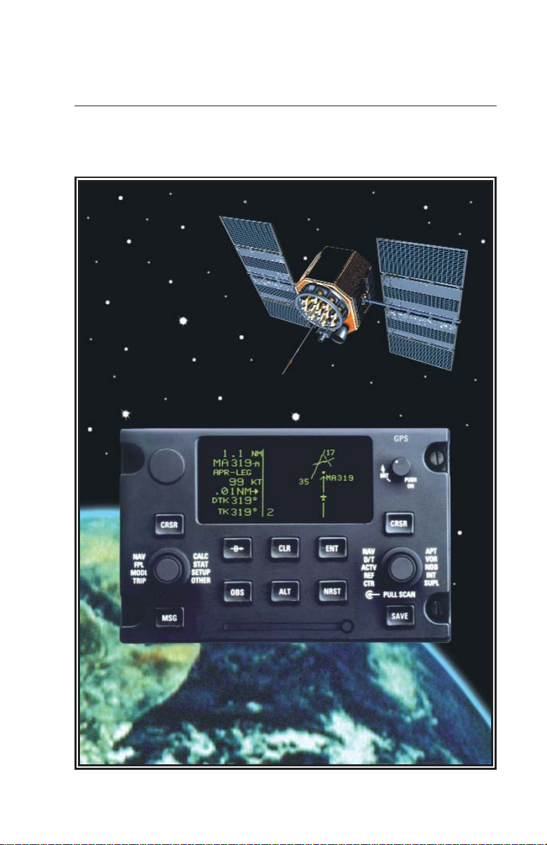
KLN 900
Global Positioning System
ORS 01, 02, and 04
Page 2

B
KLN 900 GPS
Abbreviated
Operation Manual
ORS 01, 02, and 04
IMPORTANT: Special installation procedures must be
followed in order for the KLN 900 to be certified for IFR
use. Consult the KLN 900 Flight Manual Supplement
for the operating limitations of this unit.
NOTE: Refer to section 2.8 of the KLN 900 Pilot‘s Guide (006-08796-0000)
for Database update information.
Page 3

PREVIEW OF OPERATION .................................................................1
1.0 TURN ON ......................................................................................3
2.0 BASIC OPERATION OF PANEL CONTROLS .............................6
2.1 Page Selection ........................................................................6
2.2 Entering Waypoint Identifiers ..................................................8
2.3 The Duplicate Waypoint Page .................................................9
3.0 INITIALIZATION AND TIME TO FIRST FIX ................................10
4.0 DIRECT TO OPERATION ...........................................................12
4.1 Direct To - Procedure A .........................................................13
4.2 Direct To - Procedure B .........................................................14
4.3 Direct To - Procedure C ........................................................14
4.4 To Recenter The Deviation Bar .............................................15
4.5 To Proceed Direct To Another Waypoint: ..............................15
4.6 Cancelling Direct To Operation .............................................15
5.0 THE NAVIGATION PAGES ........................................................15
5.1 The Navigation 1 Page (NAV 1) ............................................16
5.2 The Super NAV 1 Page .........................................................16
5.3 The Navigation 2 Page (NAV 2) ............................................17
5.4 The Navigation 3 Page (NAV 3) ............................................17
5.5 The Navigation 4 Page (NAV 4) ............................................17
5.6 The Navigation 5 Page (NAV 5) ............................................17
5.7 The Super NAV 5 Page .........................................................19
6.0 MESSAGE PAGE .........................................................................21
7.0 SPECIAL USE AIRSPACE ALERT ............................................22
8.0 VIEWING THE WAYPOINT PAGES ...........................................24
8.1 Selecting The Desired Waypoint Page ...............................24
8.2 The Airport 1 Page (APT 1) ................................................25
8.3 The Airport 2 Page (APT 2) ................................................26
8.4 The Airport 3 Page (APT 3) ................................................26
8.5 The Airport 4 Page (APT 4) ................................................27
8.6 The Airport 5 Page (APT 5) ................................................29
8.7 The Airport 6 Page (APT 6) ................................................29
8.8 The Airport 7 Page (APT 7) ................................................30
8.9 The Airport 8 Page (APT 8) ................................................30
8.10 The VOR Page ....................................................................31
8.11 The NDB Page ....................................................................31
8.12 The Intersection Page (INT) ................................................31
8.13 The Supplemental Waypoint Page (SUP) ...........................32
9.0 NEAREST AIRPORTS, VORS, AND NDBS ...............................32
9.1 Viewing The Nearest Airports, VORs, And NDBs .................32
9.2 Nearest Airports In An Emergency ........................................33
9.3 Continuous Display Of Nearest Airport .................................33
9.4 Selecting The Nearest Airport Criteria ...................................34
10.0 CREATING USER WAYPOINTS ..............................................35
10.1 Creating A Waypoint At The Present Position .....................35
Page 4

10.2 Creating A Waypoint As A Radial And Distance
From Another Waypoint ......................................................36
10.3 Creating A Waypoint By Entering A Latitude/
Longitude Position ..............................................................37
11.0 DELETING USER WAYPOINTS ...............................................38
12.0 CREATING AND MODIFYING FLIGHT PLANS .......................38
12.1 Creating A Flight Plan .........................................................39
12.2 Activating A Numbered Flight Plan ......................................40
12.3 Adding A Waypoint To A Flight Plan ...................................41
12.4 Deleting A Waypoint From A Flight Plan .............................41
12.5 Deleting Flight Plans ...........................................................42
12.6 Storing FPL 0 As A Numbered Flight Plan ..........................42
13.0 OPERATING FROM THE ACTIVE FLIGHT PLAN ...................43
13.1 General Procedures ............................................................43
13.2 Turn Anticipation And Waypoint Alerting .............................44
13.3 Viewing The Waypoint Pages For The Active Flight Plan
Waypoints ...........................................................................44
13.4 Combining Direct To And Flight Plan Operation .................45
13.5 The Distance/Time Pages ...................................................46
13.6 The Distance/Time 1 Page (D/T 1) ......................................46
13.7 The Distance/Time 2 Page (D/T 2) ......................................47
13.8 The Distance/Time 3 Page (D/T 3) ......................................47
13.9 The Distance/Time 4 Page (D/T 4) ......................................47
14.0 ALTITUDE ALERTING ..............................................................48
15.0 UPDATING THE DATABASE ...................................................50
16.0 ITEMS NOT COVERED IN THIS MANUAL ..............................52
Page 5

PREVIEW OF OPERATION
This abbreviated operation manual describes many of the frequently used
features of the KLN 900 in a condensed format for your convenience. It
does not replace the KLN 900 Pilot’s Guide. The KLN 900 has many very
useful features which are not described in this manual. Be sure to keep
your KLN 900 Pilot’s Guide with you in the aircraft to use as a reference.
To give you an idea of how easy the KLN 900 is to operate, the following
operational preview is presented. This operational preview assumes the
KLN 900 has been properly installed, the unit was previously operational
in the same general geographical location, and that no peripheral equipment interfaced with the KLN 900 (such as external HSIs, CDIs, autopilots, RMIs, fuel flow systems, moving map displays, etc.) is to be used at
this time. If you are using this operational preview in flight, do so only in
good VFR conditions and only with an alternate means of navigation available to cross-check position.
1. Push the power/brightness knob located in the upper right corner of the
unit to the “in” position.
2. After a few seconds of warm up, the screen will show a Turn-On page
with the words SELF TEST IN PROGRESS at the bottom of the page.
Rotate the power/brightness knob to select the desired screen brightness. If the KLN 900 is being operated without an external configuration
module, after a few seconds the Turn-On page will automatically be
replaced with the Configuration Module page. Press the E Key to
acknowledge. If the unit is being operated with an external configuration
module, after a few seconds the Turn-On page will automatically be
replaced with the Self Test page. (Note: If the KLN 900 is being used in
the take-home mode, a Take-Home Warning page is displayed before
the Self Test page and must be acknowledged by pressing E). The
Self Test page is recognizable by the date and time being shown on the
right side. The bottom left side of the Self Test page must display
ANNUN ON to indicate that the KLN 900 has passed an internal self
test.
In many KLN 900 installations the first two characters of the altimeter
setting BARO field will be highlighted in inverse video (dark characters
on a light background) on the right side of the screen. This area of
inverse video is called the cursor. Use the right inner knob to select the
correct first two characters of the altimeter setting. Next, turn the right
outer knob one step clockwise to position the cursor over the third character of the altimeter setting. Use the right inner knob to select the correct number. Once again turn the right outer knob one step clockwise to
1
Page 6

position the cursor over the last character of the altimeter setting. Use
the right inner knob to complete entering the correct altimeter setting.
Turn the right outer knob clockwise to position the cursor over the word
APPROVE? if the cursor is not there already. Press E to approve the
Self Test page.
(Note: If the KLN 900 is installed for VFR only operation,
a VFR only warning page is displayed after the self test page has been
approved. This warning page must be acknowledged by pressing
3. A database page is now displayed showing the date the database
expires or the date it expired. Press E to acknowledge the information
displayed on this page.
4. A page displaying the letters PRESENT POS at the top will now be on
the left side of the screen. In a couple of minutes or less, this page will
display the aircraft’s present position. It shows the position both in latitude/longitude and in terms of the radial and distance from a nearby
VOR. Verify that the position is correct before proceeding.
5. Press the D button. A page with the words DIRECT TO is now
displayed on the left. In step 6 you will enter the identifier of the destination airport. The identifier will have a “K” prefix for a Continental U.S. airport, a “C” prefix for a Canadian airport, or a “P” prefix for an Alaskan airport if the identifier is all letters. For example, LAX becomes KLAX. If
the airport identifier contains any numbers, there is no prefix. For
example, TX04 is entered as TX04. For other areas of the world the
airport identifier entered should be identical to how it is charted.
E
.)
6. Rotate the left inner knob until the first character of the airport identifier is
displayed. Turn the left outer knob one step clockwise to move the
flashing segment to the second character position. Rotate the left inner
knob to select the second character of the identifier. Use this procedure
to enter the complete airport identifier.
7. Press E. The right side will display a page showing the identifier,
name, and position of the airport just entered. Confirm that the correct
airport is displayed. Press E a second time to approve the airport
data.
8. A Navigation page is now on the right side of the screen. It displays the
distance, ETE, and bearing to the destination airport. In addition, it displays groundspeed, and a course deviation indicator. If the left inner
knob is rotated one step counterclockwise, you will get an enlarged
Navigation page occupying the entire screen.
2
Page 7

IMPORTANT: This abbreviated operation manual does not include any
information on how to use the KLN 900 for flying approaches or SID/STAR
procedures. Refer to the KLN 900 Pilot’s Guide and the aircraft flight
manual supplement for instructions on these procedures.
1.0 TURN ON
• Push the Power/Brightness knob located in the upper right corner of unit
to the “in” position. The unit is turned off by pulling this knob to the “out”
position.
• After a few seconds of warm up, the screen will show a Turn-On page
with the words SELF TEST IN PROGRESS at the bottom.
• Rotate the Power/Brightness knob to select the desired screen brightness.
• After a few moments the Turn-On page will automatically be replaced
with the Self Test page. The Self Test page is recognizable because it
shows the date and time on the right side.
(Note: If the unit is in the takehome mode, a page stating that the unit is in the Take-Home mode will
appear before the Self Test page. Press
E
to acknowledge the state-
ment and bring up the Self Test page.)
• Verify that the information shown on the left side of the Self Test page is
correct and that ANNUN ON is displayed in the bottom left corner. If
TEST FAIL is displayed, the KLN 900 needs service and should not be
used for navigation. If the KLN 900 is interfaced with the left/right and
up/down deviation bar (D-Bar) of an HSI or CDI, the D-Bar should be
half scale to the right and the vertical deviation bar should indicate halfscale deviation up. In some installations where the KLN 900 is interfaced
with certain EFIS systems the D-bar will be about one third scale to the
right. If interfaced to a compatible RMI, the RMI should be pointing to
130 degrees. If interfaced to a compatible DME indicator, the DME indi-
3
Page 8

cator should display 34.5 nm. If necessary, refer to the KLN 900 Pilot’s
Guide for more information. The KLN 900 stores the correct time, date
and last location of the aircraft in memory. If any of these parameters are
not correct then the GPS receiver in the KLN 900 will automatically enter a
mode in which it can determine this information. This usually will take less
than 12 minutes, so the KLN 900 should be able to determine its position
by the time you have taxied to the runway. However, if a quicker time to
lock onto satellites is required it is possible to shorten this time by giving
the KLN 900 the correct date and time. This is explained in the following
two steps.
• If the date is incorrect, rotate the right outer knob counterclockwise until
the cursor is over the entire date field. Rotate the right inner knob until
the correct day of the month is displayed. Then, rotate the right outer
knob one step clockwise to place the flashing part of the cursor over the
month field (three dashes). Rotate the right inner knob to display the
correct month. Rotate the right outer knob one step clockwise again and
then use the right inner knob to select the first digit of the correct year (a
9 for 1999, for example). Next, rotate the right outer knob one more step
clockwise and then use the right inner knob to select the second digit of
the year. When the date is correct press E.
• If it is necessary to reset the time, use the right outer knob to position the
cursor over the time zone field. Use the right inner knob to select the
desired time zone. UTC (Coordinated Universal Time, which is also
called “Zulu”) is always a good choice. Now, turn the right outer knob
one step counterclockwise to position the cursor over the entire time
field. Use the right inner knob to select the correct hour. Since 24 hour
time is used be sure to add 12 if the time is after 1:00 P.M. (2:30 P.M.
becomes 14:30). Next, turn the right outer knob one step clockwise to
position the flashing part of the cursor over the first minutes position.
Turn the right inner knob to select the correct value. Turn the right outer
knob one more step clockwise to position the flashing part of the cursor
over the second minutes position. The right inner knob is now used to
finalize the time selection. When the correct time has been entered,
press E to start the clock running.
• Turn the right outer knob clockwise to position the cursor over the first
two digits of the altimeter baro set field if the cursor is not there already.
The last KLN 900 baro setting entered is displayed.
NOTE: The KLN 900 will use an altitude input from an altitude encoder or
air data computer. Since the altitude from these devices is usually pressure altitude, altimeter baro correction is required to ensure maximum
4
Page 9

accuracy. This altitude input is used for altitude related features of the
KLN 900. Therefore, it is important to keep the altimeter baro setting
updated on the Self Test page when power is first applied to the KLN 900
and on the Altitude page each time a new baro correction is made to the
aircraft’s altimeter. The altimeter baro setting may be changed at a later
time from inches to millibars (or vice versa) on the SET 7 page. The
altimeter baro set field will not be a cursor field if the KLN 900 is interfaced
to certain air data/altimeter systems which update the baro set field when
the aircraft’s altimeter baro setting is updated.
To enter the correct baro setting, rotate the right inner knob to select the
first two digits of the correct altimeter setting. Rotate the right outer knob
one step clockwise to move the flashing cursor over the third position.
Use the right inner knob to select the correct number. Use the right outer
and inner knobs to complete the baro setting. Now press E. With the
correct altimeter setting entered, the altitude displayed on line 4 should be
correct within 100 feet.
• Use the right outer knob to position the cursor over APPROVE (if the
cursor is not there already) and press E to approve the Self Test
page.
(Note: If the KLN 900 is installed for VFR only operation, a VFR
only warning page is displayed after the self test page has been
E
approved. This warning page must be acknowledged by pressing
.)
• The screen will now display the Database page, which shows the date
the database expires or the date on which it expired. Press E to
acknowledge.
WARNING: The accuracy of the database information is assured
only if it is used before the expiration date. Use of out-of-date database information is done entirely at the user’s own risk.
• The NAV 2 page (present position) will now be displayed on the left side
of the screen and the waypoint page for the last active waypoint (before
the KLN 900 was last turned off) will be displayed on the right side. If
the last active waypoint was an airport, the APT 4 page (airport communications) will be displayed on the right side.
• When the KLN 900 is ready to navigate, the NAV 2 page will display the
present position both in terms of latitude/longitude and in terms of the
radial and distance from a nearby VOR.
5
Page 10

2.0 BASIC OPERATION OF PANEL CONTROLS
Top Left Segment
"Left Page"
Lower Left
Segment
CRSR
ı
D>CLR ENT
OBS ALT NRST
GPS
BRT
CRSR
PULL SCAN
SAVMSG
Top Right Segment
"Right Page"
PUSH
ON
Lower Right
Segment
Lower Middle
Segment
2.1 Page Selection
The screen is normally divided into five segments defined by vertical and
horizontal lines on the screen. The large top left segment is called the left
page and the large top right segment is called the right page. The small
lower left segment displays the name of the left page being displayed
while the small lower right segment displays the name of the right page
being displayed. The lower middle segment displays the mode of operation (ex: ENR-LEG is Enroute-Leg mode which is the normal mode for
enroute operations).
NOTE: When power is applied to the KLN 900 it always “wakes up” in the
Enroute-Leg mode. Only the Enroute-Leg mode is described in this
manual. In this mode the KLN 900 performs great circle navigation (the
shortest distance between two points located on the earth’s surface). The
course deviation output displayed on the unit’s internal course deviation
indicator (CDI) and provided to an external HSI or CDI is five nautical
miles left and right, full scale sensitivity. The OBS mode, approach
modes, and the oceanic mode are described in the KLN 900 Pilot’s Guide.
The two concentric knobs and C button on the left are used to control
the left page and the two concentric knobs and C button on the right are
used to control the right page. The right inner knob has an “in” and an
“out” position. It should be pushed to the “in” position for now.
The cursor is an area of inverse video (dark characters on a light background). Many pages allow you to add, delete, or change data on the
screen by first pressing the appropriate C button (left C for left page
and right C for right page) to turn the cursor function on and bring the
cursor on the screen. The appropriate concentric knobs are then used to
enter the data. When a cursor is on the screen, the page name normally
6
Page 11

shown in the lower left and right segments is replaced with a CRSR
annunciation in inverse video. Not all pages allow you to enter data, and
therefore pressing the C button while these pages are displayed will
have no effect.
There are eight types of pages that may be displayed on the left side of
the screen and ten types of pages that may be displayed on the right side.
The abbreviations for these page types are displayed around the outside
of the left and right outer knobs. The page types are different on the left
and right sides with the exception of the NAV (Navigation) type, which
appears on both sides. To select a page type, the cursor must not be displayed on the side of the screen where page selection is to be made. If
the cursor is displayed, the appropriate C button must be pressed to
turn the cursor function off. To select the NAV page type on the right side,
turn the right outer knob until NAV is displayed in the lower right segment.
The order in which the page types will be displayed is the same as the
order they are positioned around the outer knob. Thus, if APT (Airport) is
displayed in the lower right segment, turning the right outer knob one step
counterclockwise or nine steps clockwise will display NAV.
Many types of pages, such as NAV, have more than one page. There are
five NAV pages for example. Once the type of page has been selected
using the outer knob, the inner knob is used to select the specific page.
For example, if NAV 3 is displayed in the lower right segment then the
NAV 3 page is being displayed in the upper right segment. To view the
NAV 1 page turn the right inner knob two steps counterclockwise or three
steps clockwise, and NAV 1 will be displayed. Some types of pages such
as VOR only have one page. Turning the inner knob while it is in the “in”
position, will have no effect on the VOR page type and other types of
pages having only one page.
If all of the information to be displayed won’t fit on a specific page, a “+”
sign is used to indicate that there is additional information of the same
kind available for viewing. The inner knob is turned to see the additional
information but the name and number of the page doesn’t change. For
example, it is not uncommon to see APT+4. The APT 4 page always displays the communications frequencies for the selected airport. If all of the
frequencies don’t fit on one page, there will be two or more APT 4 pages
used to display all of the frequencies.
7
Page 12

The eight page types for the left side are the following:
Page Annunciation
TRI TRIP Trip Planning 0 - 6
MODE MODE Mode None
FPL FPL Flight Plan 0 - 25
NAV NAV Navigation 1 - 5
CAL CALC Calculator 1 - 7
STA STAT Status 1 - 4 *
SET SETUP Setup 0 - 9
OTH OTHER Other 0 - 4 **
* There are 5 STA pages on KLN 900’s with ORS 04 or greater
** Up to 10 pages with fuel management system and air data interfaces
The ten page types for the right side are the following:
Page Annunciation
CTR CTR Center Wpt. 1 - 2
REF REF Reference Wpt. None
ACT ACTV Active Wpt. **
D/T D/T Distance/Time 1 - 4
NAV NAV Navigation 1 - 5
APT APT Airport Wpt. 1 - 8
VOR VOR VOR Wpt. None
NDB NDB NDB Wpt. None
INT INT Intersection Wpt. None
SUP SUPL Supplemental Wpt. None
Knob Annunciation Page Name Page Numbers
Knob Annunciation Page Name Page Numbers
** Varies with the type of waypoints in the active flight plan
2.2 Entering Waypoint Identifiers
Waypoints are stored in the KLN 900 database by their ICAO
(International Civil Aviation Organization) identifiers. To use these waypoints it is only necessary to enter the ICAO identifier of the waypoint,
thus saving the labor of entering a latitude and longitude.
One area of potential confusion is airport identifiers in the Continental
United States, Alaska, and Canada. Many airports in these three areas
use identifiers having four letters beginning with a prefix letter that corresponds to the geographic area in which it is located. The prefix letter of
the Contiguous United States is “K”. Thus, the identifier for Los Angeles
International airport is KLAX, not LAX, which is the identifier of Los
Angeles VOR. Not all airport identifiers receive the prefix letter. Airport
identifiers which are a combination of letters and numbers do not receive
the prefix letter.
8
Page 13

NOTE: If you are entering an airport identifier that is all letters (no numbers), then it will begin with a “K” prefix in the Contiguous U.S., a “P” in
Alaska, or a “C” in Canada. If there are numbers in the identifier, then a
prefix is not used. For other areas of the world the airport identifier stored
in the KLN 900 database is identical to how it is charted. Like all rules
there are also exceptions to the guidelines given above. If the above rules
do not work it is possible to scan through the database using a procedure
described in section 3.7.4 of the KLN 900 Pilot’s Guide, “Selecting
Waypoints By Name or City.”
The general procedure for entering a waypoint identifier is described
below. You need not perform these steps now since they will be
described again shortly.
• If the cursor is not positioned on the screen location where you desire to
enter the waypoint identifier, press C (left C for left page or right C
for right page) to turn on the cursor function.
• If required, rotate the outer knob (left outer knob for left page or right
outer knob for right page) to position the cursor in the desired location.
• Rotate the appropriate inner knob to select the first character of the waypoint identifier.
• Turn the appropriate outer knob one step clockwise to move the cursor
to the second character position.
• Rotate the inner knob to select the second character.
• Use the outer and inner knobs in this manner until the complete waypoint
identifier is displayed. Note that you may not have to enter the last characters of the identifier because each time you enter a character, the KLN
900 offers you the first identifier in the database beginning with the characters you have entered.
• If the E is flashing in the lower middle segment of the display then
press the E button.
2.3 The Duplicate Waypoint Page
There are some waypoints in the database whose identifiers are not
unique. That is, more than one waypoint has the same identifier. When a
waypoint identifier has been entered which is not unique to a single waypoint, a Duplicate Waypoint page appears on the left side. The Duplicate
Waypoint page is used to select which of the waypoints having the same
identifier is actually desired. The waypoint identifier is displayed on the
top left of the page. To the right of the identifier is the number of
9
Page 14

waypoints in the database having the identifier. Below the identifier is a
list of the waypoint types (APT, VOR, NDB, INT, SUP) and the associated
countries which use the identifier. To see an example of a Duplicate
Waypoint page perform the following steps:
• Press D.
• Turn the left inner knob to select the letter D as a waypoint identifier. “D”
is the full identifier of several waypoints in the KLN 900 database.
• Press E. The Duplicate Waypoint page will be displayed on the left
side . At the time of this writing, there were eleven waypoints in the
database having the identifier “D”. As in this example, if there are more
than four waypoints having the same identifier, only the first four are initially shown. The list includes an NDB in Canada, an NDB in Cuba, an
NDB in the United States, and an NDB in Libya. The cursor will be over
the first waypoint listed. They are listed with the waypoint closest to the
aircraft’s present position displayed first and the waypoint farthest from
the aircraft displayed last. To view the rest, rotate the left outer knob
clockwise. Doing so will move the flashing cursor over waypoints two,
three, and four and then will cause the waypoint list to “scroll” so that the
other waypoints in the list may be seen. To select the desired waypoint,
move the cursor over the appropriate choice.
• Press E to view the waypoint page for the selected waypoint.
• Press E to approve the waypoint page.
3.0 INITIALIZATION AND TIME TO FIRST FIX
Since the KLN 900 stores its position and other required parameters in
memory when power to the unit is removed, it is seldom necessary to aid
the unit in reaching a NAV ready condition. The time required from power
on until the KLN 900 determines its present position and is therefore ready
to navigate is called “time to first fix.” The time to first fix is normally a few
minutes or less. In order for the KLN 900 to reach a NAV ready condition, it
is necessary to meet the following conditions:
1. The KLN 900’s “almanac” data must be current. Almanac data is crude
orbital information for all the satellites and is used for initial acquisition
when the KLN 900 is first turned on. This data is stored in the KLN 900’s
non-volatile memory and is considered current for up to six months.
Each satellite sends almanac data for all satellites. Since the KLN 900
routinely updates the almanac data during normal operation, the
10
Page 15

almanac data will become out-of-date only if the KLN 900 hasn’t been
used for the previous six months or longer. Collecting new almanac data
takes place automatically if the data is more than six months old. If the
almanac data is out-of-date and needs to be collected, the KLN 900 will
take a few minutes to acquire your present position (usually about two
minutes, but not more than 12 minutes). The Self Test and Database
pages should be approved.
2. The aircraft must be located such that the GPS antenna has an unobstructed view of the sky so that required satellite signals are not being
blocked. If necessary, position the aircraft away from hangars or other
obstructions.
3. It is very helpful for the KLN 900 to have the correct time, date and position to be able to determine which satellites should be in view. This information is stored in the battery backed memory of the KLN 900 so it is not
normally required to update it. If the KLN 900 has the correct time, date
and position, then the time to first fix will usually be less than two (2) minutes. If this information is not correct, then the KLN 900 will start to look
for any satellites. Eventually, the KLN 900 will find enough satellites to
determine the position of the aircraft. This process can take as long as
12 minutes. It is possible for you to update this information manually
which will allow the KLN 900 to reach a NAV ready status much faster.
To set the time and date follow steps 6 and 7 in section 3.2, “Turn-On
and Self-Test”, in the Pilot’s Guide. If it is necessary to update the position then use the following steps. Remember, if acquisition time is not
important then it is not necessary to update the time, date or position.
a. Select the Setup 1 page (SET 1) by first turning the left outer knob to dis-
play a SET type page. Next, turn the left inner knob until the SET 1 page
is selected.
b. Press the left C to bring the cursor on the page over the WPT field .
c. Use the left inner knob to enter the first character of the identifier for the
airport where you are presently located or the identifier of a navaid or
other airport which is close to you. Remember, if you are entering an airport identifier that is all letters (no numbers), then it will begin with a “K”
prefix in the Contiguous U.S., a “P” in Alaska, or a “C” in Canada. If
there are numbers in the identifier then a prefix is not used. Outside the
Contiguous U.S., Alaska, and Canada, use the airport identifiers as they
are charted.
d. Rotate the left outer knob one step clockwise to move the flashing por-
tion of the cursor to the second position and then use the left inner knob
to enter the second character of the identifier.
e. Complete entering the rest of the identifier using the left knobs in the
same manner as in step d.
11
Page 16

f. Press E to view the waypoint page on the right side.
g. Press E again to confirm the waypoint page.
NOTE: As an alternative, you can also enter the approximate latitude and
longitude of your present position directly on the SET 1 page instead of
entering a waypoint identifier.
h. Use the left outer knob to position the cursor over CONFIRM?, if it is not
there already.
i. Press E.
NOTE: The groundspeed
(KT)
and heading ( °) fields are not used for
actual initialization in an aircraft. However, if the KLN 900 is in the takehome mode, entering a groundspeed will allow the KLN 900 to “fly” along
the active flight plan (or to a direct-to waypoint) starting from the initialization
waypoint. A heading may be entered in the initial heading field while in the
take-home mode if the one offered is not desired. If the take-home mode is
used, remember to re-initialize the KLN 900 to the aircraft’s location before
re-installing it back in the aircraft.
j. Use the left knobs to select the NAV 2 page. When the KLN 900
reaches the NAV ready status and is therefore able to navigate, the NAV
2 page will display the present position. Verify that the latitude and longitude or the VOR, radial, and distance display of present position are correct.
4.0 DIRECT TO OPERATION
The D button is used to initiate Direct To operation (navigation from the
aircraft’s present position direct to a selected waypoint). When D is
pressed the Direct To page is displayed on the left side with a flashing
cursor over a waypoint identifier. The waypoint identifier which appears
on the Direct To page is chosen by the KLN 900 according to the following
rules:
1. If the Flight Plan 0 page is displayed on the left side and the cursor is
over one of the waypoint identifiers in Flight Plan 0 when D is pressed,
then that waypoint identifier will appear on the Direct To page. You will
appreciate this feature when you learn to use flight plans in section 13.0
“OPERATING FROM THE ACTIVE FLIGHT PLAN.”
2. If the scanning feature of the Super NAV 5 page is used (as described in
section 5.7) then the waypoint displayed on the Direct To page will be
the waypoint in the scan window when D was pressed.
12
Page 17

If neither of the previous two conditions are occurring, then:
3. If there is any waypoint page (APT 1-8 page, VOR page, NDB page, INT
page, SUP page, or ACT page) in view on the right side when D is
pressed, then the Direct To page will contain the identifier for the waypoint page being viewed on the right side.
If none of the previous three conditions are occurring, then:
4. When D is pressed, the waypoint identifier for the current active
waypoint will be displayed.
5. If there is no Direct To waypoint and no waypoints in Flight Plan 0 when
D is pressed, then the Direct To page will display blanks.
The application of rules 1 and 2 are described in section 13.4, “Combining
Direct To And Flight Plan Operation.” With the other in mind, here are
three procedures for initiating Direct To navigation.
4.1 Direct To - Procedure A
• Press D. The Direct To page is displayed on the left side. The cursor
will already be on the left page. A waypoint identifier may or may not be
displayed, it doesn’t matter at this point.
• Rotate the left inner knob to select the first character of the desired waypoint’s identifier. Remember to enter the “K”, “C”, or “P” prefix for certain
airports, if required (see section 2.2, “Entering Waypoint Identifiers”).
• Turn the left outer knob one step clockwise to move the flashing portion
of the cursor over the second character position.
• Rotate the left inner knob to select the second character of the identifier.
• Use the left outer and inner knobs as in the previous steps until the
desired identifier is completely displayed.
• Press E to display the waypoint page on the right side for the selected
waypoint. (If an incorrect identifier has been entered, you may immediately start using the left inner knob to re-enter the correct identifier.)
• Press E again to approve the displayed waypoint page. The right side
will display the NAV 1 page and the left side will return to the page which
was displayed prior to pressing D (unless the NAV 1 page was on the
left side or the Super NAV 5 page was selected, in which case the pages
will revert to the state they were in prior to the direct to operation). The
selected waypoint is now the active Direct To waypoint.
13
Page 18

4.2 Direct To - Procedure B
• Select the desired waypoint type (APT, VOR, NDB, INT, or SUP) on the
right page.
• Select the desired waypoint identifier using the following method:
a. Press the right C. The cursor will be over the first character in
the waypoint identifier.
b. Rotate the right inner knob to select the first character of the
desired identifier.
c. Turn the right outer knob one step clockwise to move the cursor to
the second character and then use the right inner knob to select
the second character.
d. Use the right outer and inner knobs as in the previous two steps to
complete the identifier.
• Press D. The Direct To page is displayed on the left side and it con-
tains the desired waypoint identifier.
• Press E to approve the waypoint page displayed on the right side.
The right side will display the NAV 1 page, and the left side will return to
the page which was displayed prior to pressing D (unless the NAV 1
page was on the left side in which case the pages will revert to the state
they were in prior to the direct to operation). The selected waypoint is
now the active Direct To waypoint.
4.3 Direct To - Procedure C
• Select the desired waypoint type (APT, VOR, NDB, INT, or SUP) on the
right page.
• Select the desired waypoint identifier using the following method:
a. Pull the right inner knob to the “out” position. Make sure the right
cursor function is turned off.
b. Rotate the right inner knob in either direction to scan through the
waypoint identifiers in alphabetical order. The faster you rotate the
knob, the larger the change. Numbers precede letters in the list.
c. When the desired identifier is found, press the right inner knob
back to the “in” position.
• Press D. The Direct To page is displayed on the left side and it con-
tains the desired waypoint identifier.
14
Page 19

• Press E to approve the waypoint page displayed on the right side.
The right side will display the NAV 1 page, and the left side will return to
the page which was displayed prior to pressing D (unless the NAV 1
page was on the left side in which case the pages will revert to the state
they were in prior to the direct to operation). The selected waypoint is
now the active Direct To waypoint.
4.4 To Recenter The Deviation Bar
If you get off course and wish to recenter the left/right deviation bar (DBar) to proceed direct to the same waypoint:
• Select a non-waypoint page (NAV, D/T, REF, or CTR) or the active waypoint page on the right side.
• Press D. The Direct To page is displayed on the left, containing the
active waypoint identifier.
• Press E.
4.5 To Proceed Direct To Another Waypoint:
You may proceed Direct To another waypoint other than the active one by
using Direct To procedure A, B, or C at any time.
4.6 Cancelling Direct To Operation
The primary reason for wanting to cancel Direct To operation is to return
to flight plan operation which is described later in section 13.0, “OPERATING FROM THE ACTIVE FLIGHT PLAN”. To cancel Direct To operation:
• Press D
• Press F
• Press E
5.0 THE NAVIGATION PAGES
As you would expect, the NAV (navigation) pages contain information
relating specifically to the KLN 900’s navigation capabilities. The KLN 900
has five NAV pages. Unlike any other pages, these pages may be
selected and viewed on both the left and right sides of the screen. The
procedure for selecting specific pages, including the NAV pages, was
15
Page 20

described previously under “BASIC OPERATION OF PANEL CONTROLS”. NAV pages 1,2,3, and 5 are briefly described here. The KLN
900 Pilot’s Guide must be referred to for an explanation of the NAV 4
page (vertical navigation) and for more detailed information on all other
NAV pages.
5.1 The Navigation 1 Page (NAV 1)
The NAV 1 page displays the following information:
• The active navigation leg. For Direct To operation this consists of the
Direct To symbol,
H, followed by the active Direct To waypoint identi-
fier. For the leg of a flight plan this consists of the “from” waypoint identifier and the active “to” waypoint identifier. An arrow (>>) precedes the
active waypoint identifier.
• A course deviation indicator (CDI) which displays left and right deviation
from the desired track. The deviation bar operates like a navigation
deviation needle on a conventional CDI or HSI. An on-course indication
is displayed when the deviation bar is centered on the triangle in the
middle of the CDI. In En route navigation, each dot represents one nautical mile deviation from the desired track. Therefore, the CDI shows
course deviation five nautical miles left and right of course. For
example, a deviation bar positioned two dots to the right of the center triangle indicates that the aircraft is two nautical miles to the left of course.
The center triangle also serves as the CDI’s TO/FROM indicator and
operates in the same manner as a conventional CDI TO/FROM indicator; an “up” triangle indicates “to” the active waypoint while a “down”
triangle indicates “from” the active waypoint.
• Distance (DIS) to the active waypoint.
• Groundspeed (GS)
• Estimated time enroute (ETE) to the active waypoint.
• Bearing (BRG) to the active waypoint
5.2 The Super NAV 1 Page
When the NAV 1 page is selected on both the left and right sides at the
same time, the Super NAV 1 page is displayed. The Super NAV 1 page
contains exactly the same information as the standard NAV 1 page but
spreads the data out across the entire screen making it even easier to
view.
16
Page 21

5.3 The Navigation 2 Page (NAV 2)
The NAV 2 page displays the aircraft’s present position in two formats.
The first format is in terms of the distance and radial from a nearby VOR.
(Although terminal VOR’s are in the database, they are not used on this
page since many aeronautical charts do not display a compass rose
around them for orientation purposes). The second format is in latitude
and longitude.
5.4 The Navigation 3 Page (NAV 3)
The NAV 3 page displays the following supplementary navigation information:
(If the unit is in LEG mode...)
•
circle course between two waypoints. The CDI displayed on the NAV 1
page is referenced to this DTK.
•
(If the unit is in OBS mode...)
• Actual track (TK) which is the aircraft’s present track over the ground.
• Cross track error correction - This is a text means of indicating how far
and which direction to get back on course. It is consistent with the vertical deviation bar displayed on the NAV 1 page. “FLY L 2.7 NM” means
fly left 2.7 nautical miles to get on course.
• Minimum Safe Altitude for present position (MSA) -
Desired track (DTK) which is the great
Selected Course (OBS).
IMPORTANT: refer
to section 3.9.4 in the KLN 900 Pilot’s Guide to understand the clearance provided by this altitude.
• Minimum Enroute Safe Altitude from present position to destination
(ESA).
IMPORTANT: refer to section 3.9.4 in the KLN 900 Pilot’s Guide
to understand the clearance provided by this altitude.
5.5 The Navigation 4 Page (NAV 4)
The NAV 4 page is used for advisory vertical navigation (VNAV) and for
altitude alerting. Vertical navigation operation is described in the KLN 900
Pilot’s Guide and altitude alerting is described in section 14.0.
5.6 The Navigation 5 Page (NAV 5)
The NAV 5 page provides a graphical “moving map” which displays your
aircraft’s current position relative to the active waypoint or other flight plan
waypoints. In all KLN 900 installations there are three common map orientation formats that may be selected on the NAV 5 page: a North up
(N??) display, a desired track up (DTK??) display, or an an actual track up
(TK??) display. In addition, if the KLN 900 is interfaced with a source of
heading in a suitable format then a heading up (HDG??) presentation may
also be selected. When the North up display is selected, viewing the NAV
17
Page 22

5 page is like looking at a navigation chart with North at the top. When the
desired track up display is selected, viewing the NAV 5 page is like
looking at a chart that is turned so that your course line is always pointing
up. When the actual track up display is selected, viewing the NAV 5 page
is like looking at a chart that is turned so that the direction the aircraft is
tracking over the ground is pointing up. In a no wind condition, actual
track is identical to the aircraft’s heading.
CAUTION: When using the actual track up (TK??) format it is typical
for there to be a slight delay from the time a heading change is made
until the correct map orientation is displayed. Be careful when using
either the desired track up (DTK
??
(TK
) display to not think that a heading up display is being used.
In sections 12.0 and 13.0 you will learn to use flight plan operation where
the NAV 5 page really becomes useful. When navigating using flight plan
operation, the active flight plan (FPL 0) waypoints are displayed using the
number associated with the waypoint as it appears on the FPL 0 page.
Thus, the position of the third waypoint in FPL 0 is indicated by a 3 on the
NAV 5 page. Lines connect the flight plan waypoints. An arrow points to
the active waypoint and shows the current flight plan leg.
When operating Direct To a waypoint which is not in the active flight plan,
the Direct To waypoint is indicated on the NAV 5 page by an *.
??
) display or the actual track up
To select the desired NAV 5 orientation press the appropriate C (left
C if NAV 5 page is on left side and right C if NAV 5 is on the right).
The cursor will be over the map range scale. Turn the appropriate outer
knob one step counterclockwise to position the cursor over the map orientation field. Rotate the appropriate inner knob to display N??for North up,
DTK??for desired track up, TK??for actual track up, or HDG??for
heading up. The heading up selection is not presented as a choice if
heading is not provided to the KLN 900. If the cursor is moved to the map
range scale using the outer knob or if the cursor is turned off with the C
button, then the DTK??, TK??, or HDG??annunciation is replaced with
the actual value.
If a heading input is available to the KLN 900 then heading up is usually
the best map orientation to select. Otherwise, actual track up display is
usually preferred for use in flight. However, the track up display is only
usable when the aircraft is moving 2 knots or more.
In both the North up format and the desired track up format, the aircraft’s
position is depicted by a diamond. In the actual track up format and the
heading up format, the aircraft’s position is depicted by an aircraft symbol.
The range scale is displayed in the lower right corner of the NAV 5 page.
18
Page 23

The range scale indicates the distance from the aircraft’s position (the diamond or aircraft symbol) to the top of the screen. Range scale selections
from 1 NM to 1000 NM or from 2 km to 1850 km may be made by
pressing the appropriate C and turning the appropriate inner knob.
When the NAV 5 page is displayed on the left side of the screen and any
selected waypoint page is displayed on the right side, the location of the
selected waypoint is indicated by a “+” on the NAV 5 page. Of course, the
display scale must be chosen which allows the selected waypoint to be
displayed.
5.7 The Super NAV 5 Page
The Super NAV 5 page provides you with a true moving map display of
your present position and route of flight in relation to nearby navaids and
airports. The Super NAV 5 page is displayed by selecting the NAV 5 page
on both the left and right sides at the same time. The Super NAV 5 page
has a unique format unlike any other KLN 900 page. This is done so that
you get the maximum amount of screen dedicated to graphics display.
There are no page display indicators in the lower left and right segments
of the display to tell you the Super NAV 5 page is being displayed.
However, you will soon learn to recognize the Super NAV 5 page by its
unique format. The mode annunciation, which normally appears in the
lower center segment of the screen, is now located on the far left side.
The message prompt is now located in the lower left corner of the
graphics display.
The left side of the Super NAV 5 page shows the following information:
• Distance to the active waypoint
• The active waypoint identifier
• Mode of operation
• Groundspeed
• *Estimated time enroute, cross track error, or VNAV status
• *Desired track, bearing to active waypoint, or radial from active waypoint
• *Actual track, bearing to active waypoint, or radial from active waypoint
The lines above with an * in front can be configured by the pilot to display
any of the items listed. This is done by pressing the left C and rotating
the left outer knob counterclockwise until it is over the desired line. Turn
the left inner knob to choose between items for a given line. When all
selections are complete, turn off the cursor by pressing the left C.
The map scale is also changed by using the left cursor button. To change
the map scale, press the left C to place the cursor over the map scale
factor at the bottom left corner of the map display. Turn the left inner knob
to select a map scale. The map scale choices are the same as for the
19
Page 24

NAV 5 page except there is an additional choice, AUTO, that is located
between the 1 and 1000 nm (or 2 km to 1850 km) scale factors. The
AUTO scale factor will automatically choose the smallest map scale that
will display the active waypoint and, if there is one, the waypoint after the
active waypoint. Choosing the AUTO scale factor means there is one less
item for you to worry about. This is especially helpful when conducting
non-precision approaches using the KLN 900.
Like the NAV 5 page, the Super NAV 5 page shows a graphics depiction
of the direct to waypoint or the waypoints making up the active flight plan.
But the Super NAV 5 page shows alphanumeric waypoint identifiers on
the graphics display to make orientation even easier for you.
You may elect to have nearby VORs, NDBs, and/or airports added to the
graphics display. To do so, press the right C to display a pop up menu
on the right side of the screen. Notice from the menu that a circle with a
dot in the center represents a VOR, a smaller circle represents an NDB,
and a small diamond represents an airport. The VORs, NDBs, and airports displayed are those from the nearest waypoint lists described in section 9.0, “NEAREST AIRPORTS, VORS, AND NDBS.”
When the menu is first displayed the cursor will be on the VOR selection
field. Rotate the right inner knob to display one of the following: TLH, LH ,
H or OFF.
TLH - Terminal, low altitude, and high altitude VORs are selected. In
addition, VORs of undefined class will be displayed. In some parts of the
world VORs are not classified into one of the three standard classes;
therefore, TLH must be selected to display these undefined class VORs.
LH - Only low altitude and high altitude VORs will be displayed.
H - Only high altitude VORs will be displayed.
OFF - No VORs displayed
In a like manner, NDBs and/or airports may be selected by first using the
right outer knob to move the cursor over the NDB or APT selection field
and then using the right inner knob to select ON or OFF.
The map orientation can be changed by moving the cursor to the bottom
line of the pop-up menu and rotating the right inner knob. The map orientation choices are the same as for the NAV 5 page: North up (N??),
desired track up (DTK??), actual track up (TK??), or heading up (HDG??) (if
a proper source of heading is provided to the KLN 900). Remember that
for actual track up, graphics are displayed only when the aircraft is moving
at a groundspeed greater than 2 knots.
20
Page 25

When the desired selections have been made, press the right C to
remove the menu .
One last feature of the Super NAV 5 page is that you can scan through
the waypoints of the active flight plan. This is done by pulling on the right
inner knob to place it in the “out” position. This will create a “window” at
the bottom right corner of the display that will initially contain the active
waypoint in reverse video. By turning the right inner knob it is possible to
scan through the waypoints of the active flight plan. Turning the knob
clockwise will scan through the waypoints in ascending order until the end
of the flight plan is reached. Turning the knob counter-clockwise will scan
through the waypoints in reverse order until the beginning of the flight plan
is reached. The waypoint displayed in the window will be the default waypoint when D is pressed.
The following operational hints will make using the Super NAV 5 more
enjoyable:
• It is easy to clutter the display with so much data that it is unusable.
Select a range scale that allows an uncluttered presentation of the
chosen VORs, NDBs, and airports. Or, deselect VORs, or NDBs, or airports as required. Experiment and continue to make new selections for
different phases of your trip. For example, you may find that in the
enroute part of the flight selecting high altitude VORs provides you with
enough information, while in the terminal area, selecting a smaller range
scale and more items results in the most informative display.
• Press F to instantly declutter the VOR, NDB, and airport selections
from the graphics display. Flight plan and direct to waypoints will still be
displayed. Press F again to restore the selections.
• While taxiing on the airport or flying in the traffic pattern select the 1 nm
or 2 nm scale to display the airport runway diagram instead of the usual
airport diamond symbol. All runway designations are shown on the 1 nm
scale. Only the longest runway designations are shown on the 2 nm
scale.
CAUTION: The NAV 5 and Super NAV 5 pages do not display
weather, terrain, special use airspace, or other data.
6.0 MESSAGE PAGE
Whenever the KLN 900 determines that there is a situation that requires
your attention, the MSG prompt begins flashing in inverse video at the
bottom of the display just to the right of the mode of operation. A remote
21
Page 26

message annunciator may also be installed in the aircraft instrument
panel. You should view the message at your earliest opportunity because
the unit may be alerting you to some condition of immediate concern to its
condition or to your flight. To view the message, press M. The
Message page, which takes the whole width of the display, will appear
and show the new message. Appendix B of the KLN 900 Pilot’s Guide
contains a listing of all of the Message page messages and their meanings. It is possible that several messages are displayed at one time on
the Message page. The newest message appears first and the rest in
reverse chronological order.
After reading the message, press M again to return to the pages which
were previously in view. If all of the messages cannot be displayed on
one Message page, repeated presses of M will show the other messages before returning to the pages which were previously being viewed.
Whenever a message condition exists which requires a specific action by
you, the message prompt will remain on but not flashing.
7.0 SPECIAL USE AIRSPACE ALERT
The KLN 900 database contains the location of areas of special use airspace (SUA). The types of SUA areas stored in the database and the
abbreviations used to denote these areas are the following:
Class B Airspace CL B
Class C Airspace CL C
Control Area (used outside USA) CTA
Terminal Area (used outside USA) TMA
Alert Area ALRT
Caution Area CAUT
Danger Area DNGR
Military Operations Area MOA
Prohibited Area PROH
Restricted Area REST
Training Area TRNG
Warning Area WARN
The KLN 900 will normally alert you prior to entering one of these areas
with a message prompt. When the Message page is viewed it will display
AIRSPACE ALERT and will also display the name and type of the special
use airspace. If the special use airspace is a Class B, Class C, CTA, or
TMA, the message page will also instruct you to see the Airport 4 page
(airport communications) for the primary airport so that the correct communications frequency may be determined.
22
Page 27

The SUA alert feature is three dimensional. The SUA areas are stored in
the KLN 900 database with regard to altitude when the actual SUA altitude
limitations are charted in terms of mean sea level (MSL). Therefore, if you
are flying either above or below an SUA area you won’t be inconvenienced with nuisance alert messages. However, if the actual lower limit
of a SUA is charted in terms of an altitude above ground level (AGL), then
it is stored in the KLN 900 as all altitudes below the upper limit of the SUA.
If the actual upper limit of a SUA is charted in terms of AGL, it is stored in
the KLN 900 as “unlimited”.
If the altitude input to the KLN 900 is pressure altitude from an altitude
encoder or air data computer, then you must manually update the
KLN 900 with an altimeter setting (baro correction) in order to receive
accurate SUA alerting. You may easily update the altimeter setting (barometric pressure) by pressing the A button to display the Altitude page.
The cursor will be over the inches field if “inches” was previously selected
on the SET 7 page. If “millibars” was selected on the SET 7 page then the
cursor will be over the first two digits of the millibar field. The left inner
knob is used to change the digits and the left outer knob is used to move
the cursor to the desired position. When the altimeter setting is complete,
press A to return to the pages previously in view.
CAUTION: Failure to keep the altimeter baro setting updated will
result in inaccurate special use airspace alerting. If this feature is
used, it is a good idea to update the altitude baro setting on the ALT
page each time you make a change to a aircraft’s altimeter setting.
NOTE: If there is no altitude input to the KLN 900, all altitudes will be
regarded as being within the boundary of the SUA area.
Only the outer lateral boundaries are stored for Class B, Class C, CTAs,
and TMA airspace. These SUA areas are stored as “cylinders” of airspace so all altitudes below the upper limit of these areas are considered
to be in the SUA.
The message prompt for a special use airspace alert will occur when the
aircraft’s position is at a point such that a projection of the aircraft’s
existing track over the ground is approximately 10 minutes from penetrating the outer boundary of one of these areas. It will also occur if the
aircraft is within approximately two nautical miles of one of these areas
even if the aircraft’s projected track over the ground won’t actually penetrate the SUA area. If one of the SUA areas is penetrated, another
message will state: INSIDE SPC USE AIRSPACE.
The SUA alert feature may be disabled (or enabled) on the Setup 8 (SET
8) page. After displaying the SET 8 page on the left side, press the left
23
Page 28

C to turn on the left cursor function. The left inner knob is used to display AIRSPACE ALERT ENABLE or AIRSPACE ALERT DISABLE.
If the SUA alert feature has been enabled, the KLN 900 allows you to
select a vertical buffer on the SET 8 page in order to provide an additional
layer of protection from inadvertently entering a SUA area. To select a
vertical buffer, make sure the SUA alert feature has been enabled. Press
the left C and then use the left outer knob to move the cursor over the
first position of the vertical buffer. Use the left outer knob to position the
cursor and the left inner knob to select each number. The buffer may be
selected in one hundred foot or ten meter increments. After the desired
selection has been made, press the left C to turn off the cursor function.
The vertical buffer serves to “stretch” the SUA area in both directions by
the selected buffer altitude. For example, let’s say you have selected a
buffer of 1000 feet and the actual SUA area exists from 5,000 feet MSL to
12,000 feet MSL. In this case you will receive SUA alert messages if you
fly at any altitude between 4,000 and 13,000 feet MSL.
CAUTION: It is the pilot’s responsibility to avoid those areas of special use airspace where ATC clearance to penetrate is required but
has not been obtained. The KLN 900’s special use airspace alert is
only a tool to assist the pilot and should never be relied upon as the
sole means of avoiding these areas.
8.0 VIEWING THE WAYPOINT PAGES
Waypoint pages include APT (airport), VOR, NDB, INT (intersections and
outer markers), and SUP (supplemental). Supplemental waypoints are
user-defined waypoints that have not been defined specifically as an airport, VOR, NDB, or intersection. Airport waypoints have eight pages while
the other type waypoints all have one page each.
8.1 Selecting The Desired Waypoint Page
To select a specific waypoint page:
• Select the desired waypoint type (APT, VOR, NDB, INT, or SUP) on the
right page using the right outer knob.
• Select the desired waypoint identifier using one of the following two
methods.
Method 1:
a. Press the right C. The cursor will be over the first character in
the waypoint identifier.
b. Rotate the right inner knob to select the first character of the
desired identifier.
24
Page 29

c. Turn the right outer knob one step clockwise to move the cursor to
the second character and then use the right inner knob to select the
second character.
d. Use the right outer and inner knobs as in the previous two steps to
complete the identifier.
Method 2:
a. Pull the right inner knob to the “out” position.
b. Rotate the right inner knob in either direction to scan through the
waypoint identifiers in alphabetical order. The faster you rotate the
knob, the larger the change. Numbers precede letters in the list.
c. When the desired identifier is found, press the right inner knob
back to the “in” position.
• If an airport page has been selected, rotate the right inner knob to
change the page to the desired airport page (APT 1 - APT 8).
NOTE: If an airport, VOR, or NDB waypoint identifier is not known, there
is a method described in the KLN 900 Pilot’s Guide for entering a portion
of the waypoint name and having the KLN 900 automatically retrieve the
appropriate waypoint page. In addition, for airport waypoints a portion of
the city name may be entered to retrieve the airport waypoint page. See
section 3.7.4 of the KLN 900 Pilot’s Guide, “Selecting Waypoints By Name
And City.”
8.2 The Airport 1 Page (APT 1)
The Airport 1 page contains the following information:
• Airport identifier. An arrow precedes the identifier if it is the active way-
point.
• Airport name
• If the airport underlies the outer boundary of a Class B airspace, Class C
airspace, CTA (Control Area - used outside USA), or TMA (Terminal
Area - used outside USA) the letters CL B, CL C, CTA, or TMA, respec-
tively, will appear on the left side of this line. Note that there is no altitude information applied to this criteria.
In addition, if the airport is a military airport the letters MILTRY will
appear. If the airport is a private airport, the letters PRIVAT will appear
on the right side of the line. HELIPT will appear when helpiports are dis-
played.
• The latitude and longitude of the airport reference point (the “official”
location of the airport).
25
Page 30

8.3 The Airport 2 Page (APT 2)
The Airport 2 page contains the following information:
• Airport identifier. An arrow precedes the identifier if it is the active waypoint.
• The city where the airport is located.
• The state if the airport is located in the United States, the Province if
located in Canada, or the country if located outside the United States
and Canada. A listing of the abbreviations used is contained in
Appendix D of the KLN 900 Pilot’s Guide.
• Airport elevation
• Time in relationship to UTC (Zulu). Z-5, for example, indicates local
standard time is five hours behind UTC time. If the airport is located in
an area which observes daylight savings time the information in parentheses shows the daylight savings time in relationship to UTC.
• Instrument approach information
ILS - airport has an ILS approach
MLS - airport has an MLS approach
ILS/MLS - airport has an ILS and MLS approach
NP APR - airport has a nonprecision approach and no ILS or MLS.
NO APR - airport does not have an instrument approach
• The symbol (R) indicates that the airport is serviced by an
Approach/Departure control facility having radar capability.
8.4 The Airport 3 Page (APT 3)
The function of the APT 3 page is to display runway information for the
selected airport. For many airports the first APT 3 page depicts a North
up runway diagram for the airport.
NOTE: This runway diagram is present only for those airports where
Jeppesen’s data contains the position of the runway thresholds.
The primary APT 3 page follows the runway diagram. Runway designation, lighting, and types of surface for up to five runways are displayed in
order of length, beginning with the longest. Since there are many times
when all of an airport’s runway information does not fit on one page, additional APT 3 pages are used to display the data. Remember that a “+”
inserted between the page type and the number (APT+3 in this case) is
used to indicate that there is more than one Airport 3 page.
26
Page 31

• Airport identifier. An arrow precedes the identifier if it is the active way-
point.
• The letters “RT” followed by a runway designation indicate that the
runway normally has a right hand traffic pattern. For example, RT 25
31 designates that runways 25 and 31 have a right hand traffic pattern.
• Runway number designation for both ends of the runway.
• Runway lighting availability:
L - runway lighting sunset to sunrise
LPC - runway lighting is pilot controlled
LPT - runway lighting is part time or on-request
Blank indicates no runway lighting
• Runway length
• Runway surface:
HRD - hard surface
TRF - turf
GRV - gravel
CLY - clay
SND - sand
DRT - dirt
ICE - ice
MAT - steel matting
SHL - shale
SNW - snow
(blank) - blank indicates unknown runway surface type
8.5 The Airport 4 Page (APT 4)
The APT 4 page is used to display communication frequencies for the
selected airport.
• Airport identifier. An arrow precedes the identifier if it is the active way-
point.
• Frequencies for:
ATIS - automatic terminal information service
PTAX - pre-taxi clearance
CLR - clearance delivery
GRND - ground control
RAMP - ramp/taxi control
TWR - tower
UNIC - unicom
MCOM - multicom
CTAF - common traffic advisory frequency
MF - mandatory frequency
27
Page 32

ATF - aerodrome traffic frequency
AFIS - aerodrome flight information service
CL B -Class B airspace (VFR frequency)
CL C -Class C airspace (VFR frequency)
TRSA -Terminal Radar Service Area (VFR frequency)
CTA - control area (VFR frequency used outside USA)
TMA - terminal area (VFR frequency used outside USA)
APR - approach control
DEP - departure control
CTR - center (when center is used for approach/departure control)
ARVL - arrival
RDR - radar-only frequency
DIR - director (approach control/radar)
ASOS -automated surface observation system
AWOS - automatic weather observing station
AAS - aeronautical advisory service
PCL - pilot controlled lighting
In addition to the standard VHF frequencies, HF frequencies are shown at
airports that utilize “high frequency” communications that fall in the 2000
kHz to 30,000 kHz frequency band. These are typically used in remote
areas of the world. One way to tell HF frequencies is that they do not contain a decimal point. A display of 6547 would indicate a frequency of
6,547 kHz.
Airports which have numerous communication frequencies will have multiple Airport 4 pages indicated by APT+4.
Part-time operation, such as for a control tower, is indicated with an * to
the left of a frequency.
The frequencies associated with a CL B, CL C, TRSA, CTA, or TMA are
VFR frequencies. Airports which have one of these categories of frequencies also have APR and DEP which are IFR frequencies.
Where required, APR, DEP, CL B, CL C, TRSA, CTA, and TMA frequencies are sectorized. That is, a frequency may be used only within a certain range of radials from a designated reference location. The format for
displaying the sectorization is to show the frequency first, followed by the
identifier of the associated reference point, followed next by the associated altitude restrictions.
NOTE: When an altitude restriction is shown on the Airport 4 page, the
abbreviation
the abbreviation
ABV 4000FT
BEL
means at and below the specified altitude. Likewise,
ABV
means at and above the specified altitude. Thus,
means at and above 4000 feet and
BEL 3999FT
means at
and below 3999 feet.
28
Page 33

8.6 The Airport 5 Page (APT 5)
The Airport 5 page is used to store and display user-entered remarks. Up
to 100 airports may contain these remarks. A remark may contain up to
three lines of eleven characters each. Letters, numbers, hyphens, and
spaces may be used in the remark. To enter a remark:
• Select the APT 5 page for the desired airport.
• Press the right C.
• Rotate the right outer knob until the cursor fills the entire third line of the
screen.
• Use the right inner knob to select the first character of the remark.
• Use the right outer knob to move the flashing portion of the cursor to the
second cursor position, and then use the right inner knob to select the
second character.
• Use the right outer and inner knobs to select the rest of the first line of
the remark.
• Press E to approve the first line. The cursor will move to the next line.
• Use the above procedure to select the characters for the second and
third lines of the remark. Press E to individually approve each line of
the remark.
• Press the right C to turn the right cursor function off.
The Other 4 page (OTH 4) contains a listing of all airports whose APT 5
pages contain remarks. To delete a previously entered airport remark,
select the Other 4 page, position the left cursor over the desired airport
identifier, press F, and then press E.
8.7 The Airport 6 Page (APT 6)
The APT 6 page shows aeronautical services available for the selected
airport. These services include customs, fuel, and oxygen availability, as
well as an indicator to denote the presence of a landing fee.
• Customs information is displayed as follows:
CUSTMS-FULL Customs facilities are available without restriction
NO CUSTOMS No customs facilities are available
CUSTMS-PR Customs facilities are available but require prior
request or permission for use
29
Page 34

CUSTMS-REST Customs facilities are available on a restricted
basis, check with the airport before planning to
use
CUSTMS-ADCS Customs are available for private aircraft arriving
to the U.S. from Canada or Mexico. Advance
notice of arrival to customs officers is to be
included in the flight plan transmitted to an FAA
facility. This code is used when this is the only
type customs facility available. The FAA term for
the service is “ADCUS”.
• The following fuel types are displayed:
80 80 octane
100 100 octane
100LL 100 octane, low-lead
MOGAS Automotive fuel
JET Jet fuel (any type jet fuel qualifies)
NO FUEL No fuel available
• If there are no oxygen services available at the selected airport the fifth
line will display NO OXYGEN. If any type of oxygen service is available
the fifth line will read OX and the rest of the line will display the specific
oxygen service:
H high-pressure
HB high-pressure bottled
L low-pressure
LB low-pressure bottled
ALL all of the above oxygen services are available
• The sixth line of the APT 6 page denotes the presence of a landing fee:
LANDING FEE The airport has a landing fee
NO LDG FEE The airport does not have a landing fee
NO FEE INFO Jeppesen does not have any information on whether or
not there is a landing fee for this airport
8.8 The Airport 7 Page (APT 7)
The APT 7 page is used to select SID or STAR procedures that are stored
in the database of the KLN 900. Selecting a SID or a STAR is described in
detail in the KLN 900 Pilot’s Guide.
8.9 The Airport 8 Page (APT 8)
The APT 8 page is used to select non-precision approaches for a given
airport. The details of the APT 8 page as well as approach operations are
covered in the KLN 900 Pilot’s Guide.
30
Page 35

8.10 The VOR Page
The VOR page contains the following information:
• VOR identifier. An arrow precedes the identifier if it is the active way-
point.
• The letter “D” appears following the VOR identifier if the VOR has DME
capability.
• The name of the VOR.
• The class of VOR
T - terminal
L - low altitude
H - high altitude
U - undefined
• The VOR frequency (MHz).
• The published magnetic variation of the VOR.
• The latitude and longitude of the VOR.
8.11 The NDB Page
The NDB page contains the following information for Nondirectional bea-
cons (NDBs):
• NDB identifier. An arrow precedes the identifier if it is the active way-
point.
• The name of the NDB.
• The NBD frequency (kHz)
• The latitude and longitude of the NDB.
NOTE: NDB’s which are combined with outer markers (usually called
outer compass locators) are not
stored with NDB’s. Instead, they are
stored with intersections and are found on the intersection (INT) pages.
8.12 The Intersection Page (INT)
The Intersection page contains low altitude, high altitude, approach, and
SID/STAR intersections as well as outer markers and outer compass
locators. The following information is displayed on the Intersection page:
• The intersection, outer marker, or outer compass locator name.
• The location of the intersection, outer marker, or outer compass locator
31
Page 36

expressed in terms of a radial and distance from a nearby VOR. The
KLN 900 chooses the closest VOR. It takes a few seconds for the VOR
ident, radial, and distance to be calculated and displayed.
• The latitude and longitude of the intersection, outer marker, or outer
compass locator.
In addition, the user may enter the identifier of another nearby waypoint in
the REF field, and the page will compute and display the radial and distance from the nearby waypoint to the intersection. This information is not
stored with the Intersection page and is lost when leaving the page.
8.13 The Supplemental Waypoint Page (SUP)
Supplemental waypoints are user-defined waypoints that have not been
defined specifically as an airport, VOR, NDB, or intersection. The following information is displayed on a Supplemental waypoint page:
• The name or identifier of the supplemental waypoint.
• The position of the supplemental waypoint expressed in terms of a
radial and distance from a nearby VOR. It takes a few seconds for the
VOR ident, radial, and distance to be calculated and displayed.
• The latitude and longitude of the supplemental waypoint.
In addition, the user may enter the identifier of another nearby waypoint in
the REF field and the page will compute and display the radial and distance from the nearby waypoint to the supplemental waypoint. This information is not stored with the Supplemental Waypoint page and is lost
when leaving the page.
9.0 NEAREST AIRPORTS, VORS, AND NDBS
9.1 Viewing The Nearest Airports, VORs, And NDBs
The KLN 900 computes the nine nearest airports, the nine nearest VORs,
and the nine nearest NDBs to the aircraft’s present position. There is no
“nearest” list for intersection and supplemental waypoints. To view the
nearest airports:
• Rotate the right outer knob to select the airport (APT) types.
• Pull the right inner knob to the “out” position.
32
Page 37

• Rotate the right inner knob counterclockwise to initially scan through a
complete list of all airport identifiers backward in alphabetical order.
There are actually two waypoint scan lists. These two lists are the “complete” list and the “nearest” list. The complete list contains all of the airport waypoints in the database. The nearest list consists of the nine
nearest airports to your present position.
The nearest list is positioned in front of the complete list. That is, you
must scan backwards through the complete list to reach the nearest list.
This is easy to do because the faster the knob is turned, the larger the
step is made through the list. You will know when you have reached the
nearest list because the top right portion of the waypoint page will flash
the relative position of the waypoint to the present position (NR 1 indicates
the nearest). As you scan clockwise from NR 1, NR 2, NR 3, ..., NR 9 the
next scan position is the beginning of the complete list.
Waypoint pages displayed in the nearest list do not contain a latitude and
longitude position as they do in the complete list. Instead, the bearing and
distance to the waypoint are displayed. In addition, nearest airport pages
display the length, surface, and lighting of the longest runway. Once the
nearest airport is being displayed, the other airport pages (APT 2 - APT 8)
for that airport are available for display by making sure the right inner knob
is pressed in and then turning it to select the desired airport page.
The procedure above is for viewing the nearest airports but it is equally
applicable to VORs and NDBs except that either VOR or NDB waypoint
types are selected in the first step.
9.2 Nearest Airports In An Emergency
In the event of an emergency, perform the following step to quickly get to
the beginning of the nearest airport list:
• Press N.
The waypoint page for the nearest airport is now displayed on the right
side. The right inner knob may now be used in the normal manner to
scan the other nearest airports (knob in the “out” position) or to view all
eight airport pages for a specific airport (knob in the “in” position).
9.3 Continuous Display Of Nearest Airport
When the nearest airport page is initially displayed, “NR 1” is displayed in
the upper right hand corner of the page to designate this airport as the
nearest airport. However, if you continue to fly along your flight plan with
this page selected, the same airport will be displayed and its position in
the nearest airport list will change from NR 1 to NR 2, NR 3, NR 4 ... NR 9
until finally it won’t be in the nearest airport list at all. The reason for this
33
Page 38

is that in the event of an actual emergency once you have determined
which airport you are heading for, you don’t want the nearest airport list to
update while you are maneuvering or looking up data on the other airport
pages for that airport.
There may be times, however, when you’re flying over “unfriendly” terrain
when you wish to always have to nearest airport displayed on the right
side of the screen while you view another page, such as the NAV 1 page,
on the left side. The means for doing this on the KLN 900 is the following:
1. Display the nearest airport page by pressing N.
2. Press the right C.
3. Rotate the right outer knob clockwise to position the cursor over “NR
1”. As long as the cursor is left in this position, this page will update so
that the nearest airport is always shown as the flight progresses.
9.4 Selecting The Nearest Airport Criteria
The nine airports in the nearest list are the nine airports which meet the
criteria selected on the Setup 3 page (SET 3). The SET 3 page allows
you to specify what criteria you want an airport to meet before it is considered for the nearest airport list. To specify the airport criteria:
• Select the SET 3 page on the left side.
• Press the left C to turn on the left cursor function. The cursor will
appear over the minimum runway length field.
• Use the left inner knob to select the minimum length runway desired for
the airport to qualify for the nearest airport list. Values between 1000
feet and 5000 feet in 100 foot increments or between 300 meters and
1500 meters in 100 meter increments may be selected.
• Rotate the left outer knob one step clockwise to position the cursor over
the runway surface criteria.
• Turn the left inner knob to select either HRD SFT or to select HRD. If
HRD SFT is chosen, then both hard and soft surface runways meeting
the required runway length will be included in the nearest airport list. If
HRD is chosen, then only hard surface runways will be included. Hard
surface runways include concrete, asphalt, pavement, tarmac, brick,
bitumen, and sealed. Soft surface runways include turf, gravel, clay,
sand, dirt, ice, steel matting, shale, and snow.
For example, if the minimum runway criteria selected is 2200 feet in length
and HRD surface, then only airports having a hard surface runway at least
2200 feet in length will be displayed in the nearest airport list.
34
Page 39

10.0 CREATING USER WAYPOINTS
Up to 1000 (250 for ORS 01 units) user-defined waypoints may be created. These waypoints must contain an identifier, latitude, and longitude.
This manual describes the most common methods of creating userdefined waypoints.
Regardless of which of the three methods described below is utilized for
creating a user-defined waypoint, it is first necessary to enter a unique
identifier for the waypoint. The identifier can be one to five characters in
length. To select the identifier:
• Use the right outer knob to select the supplemental (SUP) type way-
points.
• Press the right C to turn on the right cursor function. The cursor will
appear over the first character position of the identifier.
• Use the right inner knob to select the first character of the identifier.
• Turn the right outer knob one step clockwise to position the cursor over
the second character, and then use the right inner knob to select the
desired character.
• Use the right outer and inner knobs as described above to finish
selecting the identifier. The following text should now be displayed:
CREATE NEW
WPT AT:
USER POS?
PRES POS?
NOTE: If a waypoint page containing a latitude and longitude is displayed
instead of the above text, the identifier entered already exists in the user
database. Another identifier must be chosen.
10.1 Creating A Waypoint At The Present Position
Creating a user waypoint at the present position can be done by pressing
the S button. When the S button is pressed the SAVE page appears
on the right with the present position displayed. The cursor is over the
WPT Ident. This field is automatically filled with the first unused WPT from
the list USR01 - USR99 and US100 - US999. (Note that only a total of
1000 user waypoints are allowed, 250 for ORS 01 units.) The WPT name
can be changed to a name that is more meaningful. If a unique name has
been entered and the F button is pressed prior to pressing the E
button, the USxxx wpt name will reappear. If the E button is pressed
and a unique SUP ident is entered, the SUP page will display with no
cursor. If an ident is entered which is not a unique SUP ident, then the
35
Page 40

user is given an option to overwrite the waypoint name. Pressing F at
any time will cancel the save operation and the page will revert to the
page which was displayed before the SAVE page. If there are already
250 user waypoints when the E button is pressed with an unique SUP
ident, the scratchpad message "USR DB FULL" will be generated.
When the SUP page appears on the right hand side, entering a reference
identifier in the reference field will cause the radial and distance from that
reference waypoint to be computed and displayed. The reference, radial,
and distance data is lost when this page is left. When a new waypoint is
first displayed, the reference identifier will be filled in with the nearest nonterminal VOR to the waypoint.
The M button will operate normally and revert back to SAVE page after
messages are viewed. Pressing the D button, A button, the right
cursor button and N button cancels the save operation, and the button
will have its normal effect. If the SAVE button is pressed and so the
SAVE page is shown and the S button is again pressed, operation
returns to the previous active page.
10.2 Creating A Waypoint As A Radial And Distance From Another
Waypoint
The second method of creating a user-defined waypoint is to define the
waypoint’s position in terms of a radial and distance from any other
existing waypoint. To create a waypoint in this manner:
• Follow the steps presented in section 10.0 to enter a waypoint identifier.
• Rotate the right outer knob to position the cursor over USER POS? and
press E. A user waypoint page will appear with the identifier at the top
of the page and the cursor over a dashed latitude field.
• Turn the right outer knob counterclockwise to position the cursor over
the dashes to the right of REF. The next step will be to enter the identifier of an existing waypoint into this field.
• Rotate the right inner knob to select the first character of the “reference
waypoint”.
• Use the right outer knob to position the cursor and the right inner knob to
select the characters so that the entire identifier for the reference waypoint is displayed.
• Press E to see the waypoint page for the reference waypoint just
entered.
36
Page 41

• Press E again to approve this waypoint page. The waypoint page
being created will return with the cursor over the dashes to the right of
RAD.
• Use the right inner and outer knobs to select the radial (from the refer-
ence waypoint). The radial may be selected to the nearest tenth of a
degree.
• Press E. The cursor will move to the dashes to the right of DIS.
• Use the right inner and outer knobs to select the distance. The distance
may be selected to the nearest tenth of a nautical mile.
• Press E. The latitude and longitude is calculated and displayed. The
user-defined waypoint is now created.
NOTE: Entering the reference waypoint, radial, and distance is done only
to define the user waypoint’s latitude and longitude position. The reference waypoint, radial, and distance are not stored as part of the user waypoint. As soon as another page is viewed on the right side, these parameters are lost. If the SUP page for this user waypoint is displayed at a later
time, the radial and distance from the closest VOR will be displayed after
a few seconds. The original reference may, of course, be re-entered at
any time.
10.3 Creating A Waypoint By Entering A Latitude/Longitude Position
The third method of creating a user-defined waypoint is to directly enter a
latitude/longitude position. To create a waypoint in this manner:
• Follow the steps presented in section 10.0 to enter a waypoint identifier.
• Rotate the right outer knob to position the cursor over USER POS? and
press E. A user waypoint page will appear with the identifier at the top
of the page and the cursor over a dashed latitude field.
• Turn the right inner knob to display an N (for North) or an S (for South).
• Select the latitude in degrees, minutes, and hundredths of a minute by
using the right outer knob to position the cursor and the right inner knob
to select the desired numbers.
• When the complete latitude has been selected, press E. The cursor
will jump down to the longitude field.
• Turn the right inner knob to select W (for West) or E (for East).
• Use the right outer and inner knobs to select the longitude.
• Press E. The user-defined waypoint is now created.
37
Page 42

11.0 DELETING USER WAYPOINTS
A listing of all user-defined waypoints is contained on the Other 3 page
(OTH 3). The user-defined waypoints are listed by category; airports (A)
are first, VORs (V) are second, NDBs (N) are third, Intersections (I) are
fourth, and Supplemental waypoints (S) are last. Within each category,
the waypoints are alphabetized by identifier. To the right of the identifier is
the type waypoint defined (A,V,N,I, or S). If the waypoint is used in a flight
plan, the flight plan number is shown to the right of the waypoint type. If
more than five user waypoints exist, it is necessary to press the left
C and then use the left outer knob to scroll through the complete
list. To delete a user waypoint:
• Select the OTH 3 page.
• Press the left C and use the left outer knob to move the cursor over
the waypoint to be deleted. A waypoint contained in a flight plan cannot
be deleted without first either deleting the waypoint from the flight plan or
deleting the entire flight plan.
• Press F.
• Press E.
12.0 CREATING AND MODIFYING FLIGHT PLANS
The advantages of creating flight plans are: (1) the entire route of flight for
an upcoming trip can be created and stored prior to departure to reduce
workload while enroute; and (2) the routes for frequently made trips need
to be created just once and may then be recalled as required for later use.
The following rules and considerations apply to KLN 900 flight plans:
• The KLN 900 is capable of storing in its memory 25 flight plans plus an
active flight plan.
• Each of the flight plans may contain up to 30 waypoints. These waypoints may consist of any combination of published waypoints from the
database or user created waypoints.
• The flight plans are numbered 0 through 25 (FPL 0, FPL 1, FPL 2, ...,
FPL 25).
• The active flight plan is always FPL 0. The standard procedure is to
create a flight plan in one of the flight plans numbered as FPL 1, FPL 2,
FPL 3,..., or FPL 25. When one of these numbered flight plans is activated, it is copied to FPL 0, the active flight plan. This manual will refer
38
Page 43

to FPL 0 as the “active flight plan” and FPL 1 through FPL 25 as the
“numbered flight plans”. If desired, a flight plan can be created directly
in the active flight plan. This avoids creating the flight plan in a numbered flight plan and then having to activate it. The disadvantage is that
if a numbered flight plan is subsequently made active (i.e. copied to FPL
0), the one programmed directly into FPL 0 will be lost.
• Modifications may be made to FPL 0 without affecting the way it is stored
as a numbered flight plan.
• Unless Direct To operation is being used, the active flight plan (FPL 0)
must contain at least two waypoints. Otherwise, the KLN 900 system
will be flagged (i.e. the KLN 900’s navigation features will be inoperable.)
12.1 Creating A Flight Plan
To create a flight plan:
• Rotate the left outer knob to select the flight plan (FPL) type pages.
• Turn the left inner knob to select a flight plan page (preferably other than
FPL 0) which does not contain a flight plan. If all of the flight plan pages
contain flight plans, refer to section 12.5, “Deleting Flight Plans.”
• Press the left C to turn on the cursor function for the left page. The
cursor will be over the first waypoint position.
NOTE: The KLN 900 flight plan operation is designed so that the first
waypoint in the flight plan should always be the departure point.
Remember to enter the “K”, “P”, or “C” prefix for certain airports. See section 2.2, “Entering Waypoint Identifiers”.
• Use the left inner knob to select the first character of the departure way-
point identifier.
• Turn the left outer knob one step clockwise to move the flashing portion
of the cursor over the second character position and then use the left
inner knob to select the desired character.
• Use the above procedure to select the entire identifier for the first way-
point.
• Press E. A waypoint confirmation page for the identifier just entered
will be displayed on the right side. If a mistake was made and the wrong
waypoint identifier was entered, press F and begin again. If a mistake
was not made but the waypoint identifier just entered isn’t in the database, a page allowing creation of a user-defined waypoint will appear on
39
Page 44

the right side. Refer to section 10.0, “CREATING USER WAYPOINTS”,
for instruction on how to define a user created waypoint.
• Press E again to approve the waypoint page being displayed. The
cursor will move to the second waypoint position.
NOTE: A small number of waypoints are stored in the database as “flyover” waypoints. These waypoints are associated with SID/STAR procedures. “Fly-over” means that, for some reason, the governing agencies have
decided that it is important to fly directly over the waypoint instead of being
able to “cut the corner” by using turn anticipation (see section 13.2). In these
cases the KLN 900 will present a waypoint type identification page. Simply
select the way in which the waypoint is intended to be used with the left
outer knob and press E. If the SID/STAR choice is selected, the KLN 900
will disable turn anticipation for that waypoint (if previously enabled). The
KLN 900 will enable turn anticipation after the waypoint has been passed (if
turn anticipation was previously enabled). If en route is selected, then
normal turn anticipation occurs.
• Use the same procedure to enter the rest of the waypoints in the flight
plan. If the flight plan consists of five or more waypoints, the waypoints
will automatically scroll as necessary to allow entry of the next waypoint.
• When all of the waypoints have been entered in the flight plan, the left
outer knob may be rotated to move the cursor up and down and manually “scroll” through the waypoints making up this flight plan. This is
useful if the flight plan contains six or more waypoints since not all of the
waypoints can be displayed at one time. When the left outer knob is
rotated to the full counterclockwise position, the cursor will be positioned
over USE? If there are more than five waypoints in the flight plan, the
first four waypoints will then be displayed followed by the last waypoint in
the flight plan. Rotate the left outer knob to move the cursor and manually scroll to see the missing intermediate waypoints.
• Press the left C to turn off the left cursor function. Additional flight
plans may now be created in the same manner.
12.2 Activating A Numbered Flight Plan
To activate one of the previously created numbered flight plans:
• Use the left outer knob to select the flight plan (FPL) type pages.
• Rotate the left inner knob to select the desired flight plan.
• Press the left C to enable the left cursor function. The cursor will
appear over USE? (If you haven’t left the numbered flight plan page
since creating this flight plan, rotate the left outer knob all the way counterclockwise to position the cursor over USE?)
40
Page 45

• Press E to activate the flight plan in the order shown. To activate the
flight plan in inverse order (first waypoint becomes last and last waypoint
becomes first), rotate the left outer knob one step clockwise to position
the cursor over USE? INVRT? before pressing E.
• The selected flight plan is now displayed as FPL 0, the active flight plan.
Any changes made to FPL 0 will not affect how this flight plan is stored
as the numbered flight plan.
12.3 Adding A Waypoint To A Flight Plan
A waypoint may be added to any flight plan containing fewer than 30 waypoints. To add a waypoint to a flight plan:
• Press the left C to enable the left cursor function if it is not on already.
• Rotate the left outer knob as necessary to position the cursor over the
waypoint identifier which you desire to follow
Another way to think of this is to position the cursor over the position in
the flight plan you wish the new waypoint to be added. For example, if
TUL is presently the second waypoint in the flight plan and you wish to
insert GNP in the number two position in front of TUL , move the cursor
over TUL.
• Use the left inner knob to enter the first character of the waypoint being
inserted. As you begin to turn the knob the exiting waypoint in this position automatically jumps down to the next position. In the previous
example, TUL automatically moves to waypoint three.
the waypoint being added.
• Use the left outer and inner knobs in the normal manner to complete
entering the waypoint identifier.
• Press E to display the waypoint page on the right side for the identifier
just entered.
• Press E again to approve the waypoint page.
• Press the left C to turn off the left cursor function.
12.4 Deleting A Waypoint From A Flight Plan
To delete a waypoint from a flight plan:
• Press the left C to enable the left cursor function if it is not on already.
41
Page 46

• Rotate the left outer knob as necessary to position the cursor over the
waypoint to be deleted.
• Press F. The letters DEL (delete) will appear to the left of the identi-
fier and a question mark will appear to the right of the identifier. If a mistake was made and you do not wish to delete this waypoint, press F.
• Press E and the waypoint will be deleted from the flight plan. The
other waypoints in the flight plan will be correctly repositioned.
12.5 Deleting Flight Plans
To delete a flight plan which is no longer required:
• Display the flight plan (FPL 0, FPL 1, FPL 2,..., or FPL 25) which is to be
cleared.
• Make sure the left cursor function is turned off. If the left cursor is on,
press the left C to turn it off.
• Press F. The words DELETE FPL? will appear at the top of the page.
If a mistake was made and you do not wish to clear this flight plan, press
F.
• Press E to clear the flight plan.
12.6 Storing FPL 0 As A Numbered Flight Plan
The active flight plan (FPL 0) may be copied to a numbered flight plan
(FPL 1, FPL 2, ... , or FPL 25) so that it can be recalled for later use. This
may be desirable, for example, if the active flight plan was originally created on the FPL 0 page and not as a numbered flight plan. To store the
active flight plan (FPL 0) as a numbered flight plan (FPL 1, FPL 2, ... , or
FPL 25):
• Select a numbered flight plan page which does not contain any waypoints. If none exist, use the procedure described in section 12.5,
“Deleting Flight Plans”, to clear a flight plan which is no longer required.
• Press the left C to turn on the left cursor function with the cursor over
the blank first waypoint position.
• Rotate the left outer knob one step counterclockwise to position the
cursor over LOAD FPL 0?
• Press E to load the active flight plan into this numbered flight plan.
42
Page 47

13.0 OPERATING FROM THE ACTIVE FLIGHT PLAN
13.1 General Procedures
Everything described in this manual thus far is applicable to using the
KLN 900 for flight plan operation. The following rules and considerations
apply to flight plan operation while the KLN 900 is in the leg mode:
• Although many of the KLN 900 pages may be utilized while operating
along a flight plan, common page selections are the FPL 0 page on the
left side while simultaneously displaying one of three Distance/Time
pages (D/T 1, D/T 2, D/T 3) or the NAV 5 page (navigation graphics) on
the right side. Of course the other four Navigation pages may also be
used extensively. The information contained on the Distance/Time
pages is explained later in section 13.5, “The Distance/Time Pages”.
• Always verify that you are viewing the active flight plan page (FPL 0) and
not one of the other numbered flight plan pages.
• The active leg of the flight plan is designated with a BBsymbol. A leg is
defined as the course line between a pair of waypoints (a “from” waypoint and a “to” waypoint). The head of the arrow is positioned to the left
of and points to the active “to” waypoint. The tail of the BBsymbol is positioned to the left of the “from” waypoint The BBsymbol is not displayed
unless the KLN 900 is actually receiving navigation signals suitable for
navigation. (
“tricked” into thinking it is receiving signals and therefore the
can be displayed
navigation is occurring. If in doubt as to whether or not Direct To operation is occurring, view the NAV 1 page. If the top line shows the H
symbol instead of a “from” waypoint, then Direct To navigation is occurring. If it is desired to cancel the Direct To operation and operate from
the active flight plan; press D, then press F, then press E.
Note: if the unit is in the take-home mode, it has been
B
symbol
). Also, the BBsymbol will not be displayed if Direct To
• As flight plan waypoints are reached, the active leg symbol automatically
orients itself on the next leg.
• If the flight plan contains more waypoints than can be displayed on the
screen at one time, the page will automatically scroll as progress is
made along the flight plan so that the active leg is always displayed.
• The last waypoint in the flight plan is always displayed at the bottom of
the FPL 0 page, even if all of the waypoints in the flight plan can’t be displayed on the page at one time. To view intermediate waypoints, turn
the left cursor function on and use the left outer knob to manually scroll
through all of the waypoints, as desired. If scrolling is performed all the
way to the end of the flight plan, a blank waypoint position will exist so
that a waypoint may be added to the end of the flight plan.
43
Page 48

13.2 Turn Anticipation And Waypoint Alerting
Prior to reaching a waypoint in the active flight plan, the KLN 900 will provide navigation along a curved path segment to ensure a smooth transition between two adjacent legs in the flight plan. That is, the CDI or HSI
left/right deviation will be referenced to the dashed line in the following
figure. This feature is called turn anticipation. The transition course is
based upon the aircraft’s actual groundspeed and the amount of course
angle change between the two legs. The KLN 900 automatically
sequences to the next leg after passing the midpoint in the transition segment.
Approximately 20 seconds prior to the beginning of turn anticipation, the
arrow preceding the active waypoint identifier will begin flashing on the
FPL 0 page and on any Navigation page, Distance/Time page, or waypoint page displaying the active waypoint identifier. The active waypoint
identifier will start to flash on the Super NAV 5 page. This is called “waypoint alerting”. If an external waypoint alert annunciator is mounted in the
aircraft, this annunciator will begin flashing at the same time.
To utilize the turn anticipation feature, start the turn transitioning to the
next leg in the flight plan at the very beginning of turn anticipation. This
occurs when the desired track (DTK) displayed on the NAV 3 or Super
NAV 5 page changes to the value for the next leg. A message prompt
also begins flashing at the beginning of turn anticipation. When the message is viewed, it states: ADJ NAV IND CRS TO XYZ°, where XYZ is the
new course you should select on the HSI or CDI.
Note: This message is
not displayed if the KLN 900 is interfaced with an EHSI or HSI having a
course pointer automatically slewed to the correct desired track by the
KLN 900.
external waypoint alert annunciator stops flashing and goes on steady.
Turn anticipation becomes inactive when transition to the next leg has
been made.
The beginning of turn anticipation is also indicated when the
If desired, turn anticipation may be disabled (or enabled) on the Setup 6
page (SET 6) using the left C and the left inner knob to select between
DISABLE or ENABLE. If turn anticipation is disabled, navigation is provided all the way to the waypoint and waypoint alerting occurs approximately 36 seconds prior to actually reaching the waypoint.
13.3 Viewing The Waypoint Pages For The Active Flight Plan
Waypoints
The waypoint page(s) for each of the waypoints in the active flight plan
may be easily displayed by selecting the Active Waypoint page (ACT)
type on the right side. When the ACT page type is first selected, the waypoint page for the active waypoint will be displayed. The location of the
waypoint in the flight plan (waypoint 1, waypoint 2, etc.) is annunciated
with a number to the left of the identifier. In addition, an arrow to the left of
44
Page 49

the waypoint number designates the active way-
WPT 3
point. The letter to the far right of the identifier
designates the type of waypoint: A = airport, V =
VOR, N = NDB, I = intersection, S = supple-
WPT 2
mental, or T=Terminal (see KLN 900 Pilot’s
Guide). For VOR’s having DME capability, the
letter D is displayed between the VOR identifier
and the V. To view the other waypoints in the
flight plan, pull the right inner knob to the “out”
position and turn it to view each of the waypoints
WPT 1
in the order they are contained in the flight plan.
For airport waypoints, the right inner knob may be pushed back to the “in”
position and rotated to display any of the six airport pages. Pulling the
knob back out will allow further scanning of the waypoint pages in the
active flight plan.
13.4 Combining Direct To And Flight Plan Operation
It is very common when using flight plan operation to use the Direct To
function to proceed directly to a waypoint which exists in the flight plan.
For example, after takeoff it is very normal to receive radar vectors in the
terminal area and then be given a clearance direct to the first point in the
flight plan that was filed. The KLN 900 makes this kind of operation very
easy to accomplish. Whenever you do a Direct To operation to a waypoint which is in the active flight plan (FPL 0) the system will provide navigation to the waypoint and then automatically resume navigation along the
flight plan when the Direct To waypoint is reached. Waypoints which exist
prior to the Direct To waypoint in the active flight plan are bypassed. Of
course, the active flight plan will never be resumed if the Direct To operation is to a waypoint which is not in the active flight plan.
Any of the several methods previously described for initiating Direct To
operation may be used, although the following are the easiest for this
application. The first procedure takes advantage of rule number 1
described in section 4.0.
• Select the FPL 0 page on the left side.
• Press the left C and then use the left outer knob to position the cursor
over the desired waypoint.
• Press D. The waypoint page for the selected waypoint in FPL 0 will
be displayed on the right side.
• Press E to approve the waypoint page. The Direct To waypoint iden-
tifier in the active flight plan will now be preceded by just an arrow. The
BB
symbol is not displayed since there is no “from” waypoint in the flight
plan.
45
Page 50

The second method takes advantage of rule number 2 described in
section 4.0. To use this method:
• Display the Super NAV 5 page by selecting NAV 5 on both sides of the
display.
• Pull out the right inner knob. A “window” will appear in the bottom right
hand corner that has the current active waypoint in reverse video.
• Turn the right inner knob to scan through the waypoints of the active
flight plan until the desired waypoint is displayed.
• Press D. The waypoint page for the selected waypoint from the Super
NAV 5 page will be displayed on the right side.
• Press E to approve the waypoint page. The active waypoint is now the
waypoint selected from the Super NAV 5 page. The KLN 900 will return
the display to the Super NAV 5 page.
If for some reason it is desired to cancel the Direct To operation prior to
reaching the Direct To waypoint in order to proceed along the flight plan
leg, press D, then press F, and then press E.
13.5 The Distance/Time Pages
As stated earlier it is common to use the Distance/Time pages in conjunction with flight plan operation. The Distance/Time pages are specially
designed to be most useful when the active flight plan page (FPL 0) is displayed simultaneously on the left side.
13.6 The Distance/Time 1 Page (D/T 1)
When the FPL 0 page is displayed on the left side and the D/T 1 page is
displayed on the right side, the distance (DIS) and estimated time enroute
(ETE) are displayed for each of the active flight plan waypoints. The dis-
tance displayed is the cumulative distance from the aircraft’s present
position to each waypoint along the flight plan route. The ETE is dis-
played in hours:minutes. If Direct To operation is occurring to a waypoint
that is not in the active flight plan then the D/T 1 page is blank when the
FPL 0 page is displayed on the left.
If a numbered flight plan page (FPL 1 through FPL 25) is displayed on the
left side, the distances displayed are from the first waypoint in the flight
plan and have nothing to do with the aircraft’s present position. No ETE’s
are then shown.
If a non-flight plan page is displayed on the left, the format of the D/T 1
page changes to display just the distance and ETE for the active waypoint
and for the last waypoint in the flight plan.
46
Page 51

13.7 The Distance/Time 2 Page (D/T 2)
When the FPL 0 page is displayed on the left side and the D/T 2 page is
displayed on the right side, the distance and estimated time of arrival are
displayed for each of the active flight plan waypoints. The distances are
as described for the D/T 1 page. The time zone associated with the estimated time of arrival is annunciated at the top right of the D/T 2 page.
The time zone may be changed by enabling the right cursor function to
bring the cursor over the time zone and then turning the right inner knob to
select the desired time zone. Changing the time zone on the D/T 2 page
changes the time zone on other pages where time is displayed.
If a numbered flight plan page other than FPL 0 is displayed on the left
side, no estimated times of arrival are displayed.
If a non-flight plan page is displayed on the left side, the format of the D/T
2 changes to display just the distance and estimated time of arrival for the
active waypoint and for the last waypoint in the flight plan.
13.8 The Distance/Time 3 Page (D/T 3)
When any flight plan page is displayed on the left side and the D/T 3 page
is displayed on the right side, the distance and desired track (DTK) are
displayed. The distances are as described for the D/T 1 page. The
desired track is the great circle course between two waypoints. You
should view the diagram in Appendix A of the KLN 900 Pilot’s Guide if you
are unfamiliar with this term.
If a non-flight plan page is displayed on the left side, the format of the D/T
3 page changes to display just the distance and desired track for the
active waypoint and for the next waypoint in the flight plan. Note that
this is different than for the D/T 1 and D/T 2 pages.
13.9 The Distance/Time 4 Page (D/T 4)
The format of the D/T 4 page does not change. It displays on a single
page the pertinent times for the flight regardless of what is displayed on
the left page and regardless of whether flight plan or Direct To operation is
occurring. The information displayed on the D/T 4 page is the following:
• The destination waypoint
• The selected time zone. The time zone may be changed by pressing the
right C and using the right inner knob to select the desired time zone.
• DEP -The departure time. There are two definitions of departure time
depending on what has been selected on the Setup 4 page (SET 4). If
the SET 4 page displays RUN WHEN GS > 30 KT, then the departure
time is that time when the groundspeed first reached 30 knots. If the
47
Page 52

SET 4 page displays RUN WHEN POWER IS ON, then the departure
time is the time when power was applied to the KLN 900. The SET 4
page may be changed by pressing the left C while the SET 4 page is
displayed on the left side and then rotating the left inner knob. Press the
left C again to turn the left cursor function off.
• TIME -The present time. The time may be reset on the Self Test page at
system turn-on or on the SET 2 page.
• ETA - The estimated time of arrival at the destination waypoint.
• FLT - The flight time. If RUN WHEN GS > 30 KT is selected on the SET
4 page, then flight time is the amount of time that the aircraft’s groundspeed has been above 30 knots. Normally, this will be the time since
takeoff. However, time spent at groundspeeds less than 30 knots such
as intermediate stops without shutting down power or helicopter hovering is not counted as flight time. If RUN WHEN POWER IS ON is
selected on the SET 4 page, then flight time is the time since power on.
• ETE - Estimated time enroute to the destination waypoint.
14.0 ALTITUDE ALERTING
If your aircraft does not already have an altitude alerting capability you
may wish to use the KLN 900’s capability of assisting you with altitude
management during your flying. Altitude alerting allows you to select a
target altitude and it then provides you with an aural alarm 1000 feet prior
to reaching the selected altitude, another aural alarm upon reaching the
selected altitude, and another aural alarm if you deviate from the selected
altitude.
To use altitude alerting:
1. Press A. The Altitude page will be displayed on the left with the cursor
over the first two digits of the altimeter baro set field. The NAV 4 page
will be displayed on the right with the cursor over the first digit of the
selected altitude field .
NOTE: The units of the altimeter baro set may be changed on the SET 7
page.
2. Use the left knobs to update the altimeter baro setting if required. There
are three cursor positions. Use the left outer knob to move the cursor
and the left inner knob to change digits. With the proper altimeter baro
setting, the indicated altitude (IND) on the right should be the same of
the aircraft’s actual altimeter.
48
Page 53

NOTE: There may be some difference (less than 100 feet) between the
indicated altitude
(IND)
and the aircraft’s actual altitude if the altitude input
to the KLN 900 is from an altitude encoder because these encoders only
provide altitude in 100 foot increments.
3. Turn the left outer knob one step clockwise to position the cursor over
the ALERT: field. If OFF is displayed, turn the left inner knob to select
ON. When alerting is enabled, an arrow to the right of ON points to the
selected altitude on the right side of the screen.
4. Select a warn altitude by using the left outer knob to position the cursor
over the WARN: field. Use the left inner knob to select the desired warn
altitude. It is selectable in one hundred foot increments from 200 feet up
to 900 feet or in ten meter increments from 60 meters up to 270 meters.
Normally, you will use the same warn altitude all the time so you only
have to enter this the first time you use altitude alerting. The recommended warn altitude is 300 feet (or 90 meters).
5. Enter the selected altitude one digit at a time in the SEL field of the NAV
4 page by using the right outer knob to position the cursor over the
desired digit and the right inner knob to change the digits until the entire
selected altitude is displayed .
Only the selected altitude field (SEL) and the indicated altitude (IND) of
the NAV 4 page are used for altitude alerting. The rest of the NAV 4 page
is used for vertical navigation which is described in section 5.2 in the KLN
900 Pilot’s Guide.
6. Press A to return to the previously displayed pages.
7. The aural alarm activates as follows:
• 1000 feet prior to reaching the selected altitude - alert by three
short tones
• Upon reaching the selected altitude - alert by two short tones
• Deviating above or below the selected altitude by more than the
warn altitude - alert by four short tones
NOTE: Due to the resolution of the altitude input, it may be necessary to
descend slightly below or climb slightly above the selected altitude before
the two tones are activated indicating that the selected altitude has been
reached. This selected altitude alert must be activated to arm the system
for providing the altitude deviation alert. When a DC altitude source is
used, the resolution of the altitude input is reduced and the usability of the
advisory VNAV is reduced.
49
Page 54

The KLN 900 can provide the aural alarm tones in either of two ways: it
may be connected to an audio input of an audio amplifier contained in an
audio panel so that the aural alarm is heard through the aircraft’s speaker
and headphones. Or the KLN 900 may be interfaced with an external
tone generator installed in the aircraft.
In order to use altitude alerting, the KLN 900 must have an altitude input.
If the altitude input is from an altitude encoder or from an air data computer not having a baro altitude output, then it will be necessary for you to
manually input the proper altimeter setting in order to get accurate
alerting. Remember, the altitude coming from an encoder is pressure altitude and must be corrected with the proper altimeter setting to convert to
actual altitude. This altimeter setting is easily accomplished by entering
the altimeter baro setting on the Altitude page. Press A to display the
Altitude page. Use the left knobs to make the altimeter baro setting.
Press A again to return to the pages previously being displayed. It’s so
easy you have no excuses for not keeping the baro setting updated!
CAUTION: The altitude alerting feature will only be accurate if the
altimeter baro correction is kept updated. If altitude alerting is used,
it is a good idea to update the altimeter baro set on the ALT page
each time you make a change to the aircraft’s altimeter setting.
The volume of the aural alarm tone is changeable on the SET 9 page.
Press the left C to activate the left cursor and use the left inner and
outer knobs to select a desired value between 00 and 99. Increasing
numbers increases the volume.
15.0 UPDATING THE DATABASE
The database is housed in a PCMCIA card which plugs directly into the
front of the KLN 900. It is designed so that there are two ways for the
user to keep the database current. Honeywell makes these two types of
update services available to you in a choice of several subscription or
random update programs. See section 2.8 of the KLN 900 Pilot’s Guide
for details on these programs.
The first method of database update is to remove the old card and insert a
current card. This method involves returning the old card to Honeywell.
This method is described in this section of the manual but more detailed
instructions are presented in section 2.4.2 of the KLN 900 Pilot’s Guide.
Because of the wide range of shipping costs and import/export regulations
for different countries, this method is available for use only in the United
States.
50
Page 55

The second is to electronically update the database by means of 3.5”
diskettes supplied by Honeywell and a laptop computer. This method
does not involve removing the KLN 900 from the aircraft’s instrument
panel. A data port on the front of KLN 900 provides a means of interfacing the unit with the computer via an interface cable. The diskettes are
not returned to Honeywell. This method of update is for use anywhere in
the world that diskettes may be shipped. Directions for updating the database using a laptop computer are contained in section 2.4.1 of the KLN
900 Pilot’s Guide.
In order to utilize the first method of database update, exchange the KLN
900 PCMCIA card. Follow these steps to update the KLN 900 database
by removing the old card and inserting the new card:
• Remove the old database card by pulling it straight out the front of the
KLN 900.
• Remove the new database card from its shipping container. Note that
the label on the card indicates which side is up and which end to insert
into the KLN 900. Insert the new card into the front of the unit.
• The container which was used to ship the new card to you is used to
return the old card back to Honeywell. A return shipping label is
included in the container. Remove the backing from the label and place
it in the address position of the shipping container.
• Insert the old card into the container. Peel off the protective backing
from the adhesive on the end flap on the container. Press the flap
against the adhesive to seal the container.
• Please return the old card promptly by mailing immediately at any
mailbox. No postage is required if mailed from within the U.S. Users
will be billed for cards not returned, and no additional cards will be sent
until either the old card or payment for the old card is received.
51
Page 56

16.0 ITEMS NOT COVERED IN THIS MANUAL
Be sure to take the time to read through the KLN 900 Pilot’s Guide. In
some cases more detail is provided on subjects covered in this manual.
Hundreds of illustrations are used to make learning to use the KLN 900 as
easy as possible. In addition, the Pilot’s Guide describes many very
useful KLN 900 features you will want to learn to use which are not covered in this manual. Some of these features include:
• Non-precision approach operations
• SID/STAR selection and use
• Database coverage areas
• RAIM prediction
• Finding waypoints when the identifier isn’t known by entering the name
or city
• Trip planning
• VNAV operation
• Displaying the nearest FSS and frequency
• Displaying the ARTCC and frequency for the aircraft’s present position
• Creating “Reference” waypoints
• Creating ARTCC “Center” waypoints
• Pressure and density altitude calculations
• True airspeed (TAS) calculations
• Wind speed and direction calculations
• Updating the database using a laptop computer
• Using the Height Above Airport feature
• Displaying sunrise and sunset for any waypoint
• Other mode of operation - “OBS”
• Viewing the status of the GPS satellites
• Configuration Data and Messages
• Tandem Operation
• Dual Operation
• Oceanic/Remote Operation
• Fault Detection and Exclusion (FDE)
• Introduction to the PreFlight Software
• AUTO/USER magnetic variation
• Operation without a database card
• Using the Take-home mode
• Message Page Messages
• Status Line Messages
• Sample trips
• And much more !
52
Page 57

Honeywell Inc.
Electronic & Avionics Systems World Headquarters
Business & General Aviation Enterprise
One Technology Center
23500 West 105th Street
Olathe, KS 66061
U.S.A.
Honeywell General Information
between 8 a.m. and 5 p.m. Central Time, Monday thru Friday.
Tel: (800) 347-5462 (U.S. Callers)
Tel: (913) 712-0400 (International)
FAX: (913) 712-1301 (General Information)
FAX: (913) 712-1335 (Domestic Orders)
FAX: (913) 712-1302 (International Orders)
web site: www.bendixking.com
Honeywell Customer Service & Product Support
Tel: (800) 257-0726 (U.S. Callers)
Tel: (913) 712-0600 (International)
FAX: (913) 712-1306 (Product Support)
FAX: (913) 712-1313 (Repair & Overhaul)
Honeywell Navigation Services, Mail Drop #66
Tel: (800) 247-0230 (U.S. Callers)
Tel: (913) 712-3145 (International)
FAX: (913) 712-3904
email: nav.database@honeywell.com
web site: www.gpsdatabase.com
Copyright © 1999 by Honeywell International Inc. All rights
reserved.
Rev. 1, January 1999, Part Number 006-08797-0000
Printed in the USA
N
 Loading...