


KLN 900
Table of contents
 Loading...
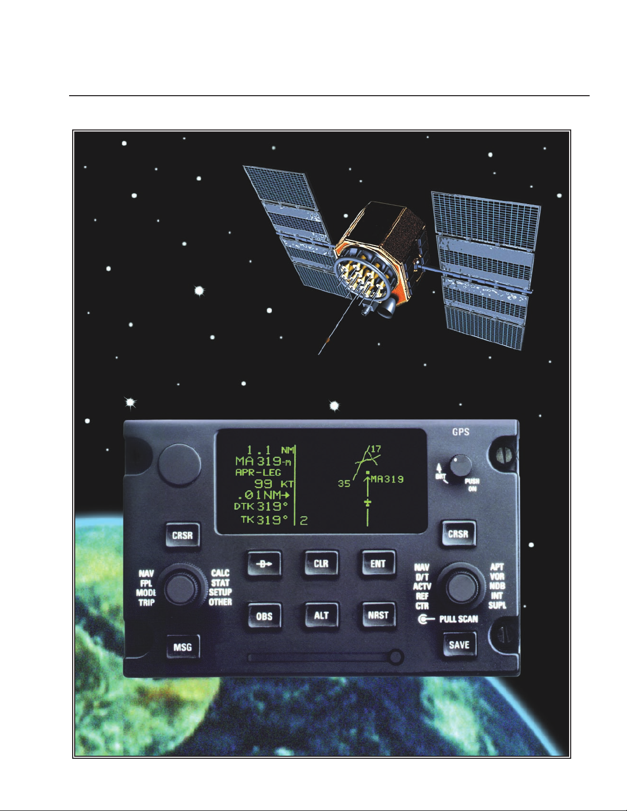
Pilot’s Guide
KLN 900
Global Positioning System
ORS 01, 02 and 04

i
Rev 2
KLN 900 PILOT’S GUIDE
006-08796-0000
for KLN 900s with
OPERATIONAL REVISION STATUS (ORS) 01, 02, and 04
IMPORTANT: Special installation procedures must be
followed in order for the KLN 900 to be certified for IFR use.
Consult the KLN 900 Flight Manual Supplement for the
operating limitations of this unit.
For Important
Database Update
Information
See Section 2.8

ii
Rev 2
THIS PAGE INTENTIONALLY LEFT BLANK

iii
Copyright © 1999 by Honeywell Internationall Inc. All rights reserved.
NN
Honeywell International Inc.
Electronic & Avionics Systems World Headquarters
Business & General Aviation Enterprise
One Technology Center
23500 West 105th Street
Olathe, KS 66061
U.S.A.
Honeywell General Information
between 8 a.m. and 5 p.m. Central Time, Monday thru Friday.
Tel: (800) 347-5462 (U.S. Callers)
Tel: (913) 712-0400 (International)
FAX: (913) 712-1301 (General Information)
FAX: (913) 712-1335 (Domestic Orders)
FAX: (913) 712-1302 (International Orders)
web site: www.bendixking.com
Honeywell Customer Service & Product Support
Tel: (800) 257-0726 (U.S. Callers)
Tel: (913) 712-0600 (International)
FAX: (913) 712-1306 (Product Support)
FAX: (913) 712-1313 (Repair & Overhaul)
Honeywell Navigation Services, Mail Drop #66
Tel: (800) 247-0230 (U.S. Callers)
Tel: (913) 712-3145 (International)
FAX: (913) 712-3904
email: nav.database@Honeywell.com
web site: www.gpsdatabase.com
Bendix/King and the Bendix/King logo are
registered trademarks of Honeywelll Inc.,
U.S. Patent & Trademark Office.
Rev. 2, January 1999, Part Number 006-08796-0000
Printed in the USA
Rev 2

Rev 2
iv
OPERATIONAL REVISION STATUS (ORS)
IMPORTANT
THIS KLN 900 PILOT’S GUIDE IS APPLICABLE TO KLN 900 SYSTEMS WITH THE
FOLLOWING LEVELS OF OPERATIONAL REVISION STATUS (ORS):
ORS 01, 02, or 04
This ORS level is annunciated in the upper right corner of the Turn-On page each time the KLN
900 system is turned on. While all KLN 900’s with like ORS levels have the same general operational characteristics as explained in this manual, it is still the pilot's responsibility to review the
aircraft’s KLN 900 Flight Manual Supplement for unique characteristics which may be applicable
to the aircraft’s KLN 900 installation.
EXPLANATION OF DIFFERENCES IN ORS LEVELS:
ORS 02: Operational characteristics are similar to ORS 01 with the exception of the following
primary differences:
(1) Metric units were added, and a unit selection was added to the SET 7 page.
(2) Tandem mode was improved so that flight plan and user waypoint data would automatically
be transferred from one unit to the other.
(3) Added options to the SET 10 page which allow the user to transfer flight plan and user way-
point data to or from either a personal computer or a PCMCIA data card.
(4) The maximum number of user waypoints was increased from 500 to 1000.
(5) An option for USER-specified magnetic variation was added to the SET 2 page.
(6) ORS 02 meets B-RNAV (MNP-5) requirements per FAA AC 90-96 and JAA AMJ 20X2.
ORS 04: Operational characteristics are similar to ORS 02 with the exception of the following
primary differences:
(1) ORS 04 meets requirements for Oceanic / Remote Operation per FAA Notice 8110.60.
(2) The ability for the KLN 900 to operate in a dual installation and to transfer flight plan and
waypoint data from one unit to another was added.
(3) RAIM and FDE availability indicators were added to the STA 2 page.
(4) A local (LCL) time zone option was added to the SET 2 page.
NOTE
ALL NAVIGATION DATA PRESENTED BOTH IN THE TEXT AND IN THE ILLUSTRATIONS OF
THIS PILOT’S GUIDE IS INTENDED FOR EXAMPLE ONLY AND, THEREFORE, IS NOT TO
BE USED FOR ACTUAL NAVIGATION.

v
Revision History and Instructions
Manual KLN 900 Pilot’s Guide
Revision 2, January 1999
Part Number 006-08796-0000
This revision is a complete manual revision and supersedes previous revision level
manuals. Superseded manuals should be discarded.
Rev 2

vi
Rev 2
Revision History and Instructions
Manual KLN 900 Pilot’s Guide
Revision 1, February 1998
Part Number 006-08796-0000
This revision is a complete manual revision and supersedes previous revision level
manuals. Superseded manuals should be discarded.

I
The KLN 900 is an extremely sophisticated navigational
device, capable of providing highly accurate navigation
over most parts of the world. You will be amazed at all
of the navigational and other aeronautical functions that
the unit can perform. However, you don’t need to master all of the KLN 900’s capabilities at once. In just a
short time you will be confidently using it to make your
flying duties easier and more enjoyable. You will learn
new features as you have a need or desire to learn
them and soon will establish the best way of using the
KLN 900 to meet your particular flying requirements.
Don’t let the size of this Pilot’s Guide intimidate you! It
is written in plain, simple English instead of “computereeze” and it assumes you are not an experienced user
of GPS or other types of long range navigation equipment. If you are experienced, so much the better. This
Pilot’s Guide also includes hundreds of sample screen
figures and other illustrations to make your learning easier. It is designed so that you can start at the front and
progress in the order presented; however, you may
want to skip around and learn things in your own order.
There are several appendices in the back that you may
find useful from time to time.
As you become proficient with using the KLN 900, don’t
be tempted to rely on it as the sole means of navigation.
A good pilot never relies on just one source of navigation for either VFR or IFR flying. Cross check your position using VOR, DME, ADF, or other navigational
devices you may have in the cockpit - including your
eyes!
Be sure and keep a copy of this Pilot’s Guide in the
aircraft to use as a reference. You never know when
you may have a question you’ll want to look up.
One last thing. Don’t get so involved in learning to use
the KLN 900 that you forget to fly the aircraft. Be careful,
and remember to keep a close eye out for other aircraft.
NOTE: A white border is used around data on some of
the figures in this Pilot’s Guide to indicate that the data
inside the border is flashing. An example of this is figure 3-6 where the white border around the characters
ACKNOWLEDGE? and ENT is used to indicate that
both are flashing.
Rev 2
INTRODUCTION

II
No doubt you are going to read this entire manual just as
soon as you possibly can. But just to get an idea of how
easy the KLN 900 is to operate, the following operational
preview is presented. This operational preview assumes
that the KLN 900 has been properly installed, that the
KLN 900 was previously operational in the same general
geographical location, and that no peripheral equipment
interfaced with the KLN 900 (such as external HSIs,
CDIs, autopilots, RMIs, fuel flow systems, moving map
display, etc.) is to be used at this time. If you are using
this operational preview in flight, do so only in good VFR
conditions and only with an alternate means of navigation
available to cross-check your aircraft’s position.
1. Push the power/brightness knob located in the
upper right corner of the unit to the “in” position.
2. After a few seconds of warm up, the screen will
show a Turn-On page with the words SELF TEST
IN PROGRESS at the bottom of the page. Rotate
the power/brightness knob to select the desired
screen brightness. After a few seconds the TurnOn page will automatically be replaced with the Self
Test page. (Note: If the KLN 900 is being used in
the take-home mode, a Take-Home Warning page
is displayed before the Self Test page and must be
acknowledged by pressing E.) The Self Test
page is recognizable because it shows the date
and time on the right side. If the date and time are
incorrect by more than 10 minutes, refer to section
3.2 steps 6 and 7. The bottom left side of the Self
Test page must display ANNUN ON to indicate that
the KLN 900 has passed an internal self test.
In most KLN 900 installations the first two characters of the altimeter setting BARO field will be highlighted in inverse video (dark characters on a light
background) on the right side of the screen. This
area of inverse video is called the cursor. Use the
right inner knob to select the correct first two characters of the altimeter setting. Next, turn the right
outer knob one step clockwise to position the cursor over the third character of the altimeter setting.
Use the right inner knob to select the correct number. Once again turn the right outer knob one step
clockwise to position the cursor over the last character of the altimeter setting. Use the right inner
knob to complete entering the correct altimeter setting.
Turn the right outer knob clockwise to position the
cursor over the word APPROVE? if the cursor is
not there already. Press E to approve the Self
Test page. (Note: If the KLN 900 is installed for
VFR only operation, a VFR only warning page is
displayed after the self test page has been
approved. This warning page must be acknowledged by pressing E .)
3. A Database page is now displayed showing the
date the data base expires or the date it expired.
Press E to acknowledge the information displayed on this page.
4. A page displaying the letters PRESENT POS at
the top will now be on the left side of the screen.
In a couple minutes or less, this page will display
the aircraft’s present position. It shows the position both in latitude/longitude and in terms of the
radial and distance from a nearby VOR. Verify
that the position is correct before proceeding.
5. Press the D button. A page with the words
DIRECT TO is now displayed on the left.
In step 6 you will enter the ICAO identifier of the
destination airport. The identifier will have a “K”
prefix for a Continental U.S. airport, a “C” prefix
for a Canadian airport, or a “P” prefix (in many
cases) for an Alaskan airport if the identifier is all
letters. For example, LAX becomes KLAX. For
Canada and the U.S., if the airport identifier contains any numbers, then there is no prefix. For
example, TX04 is entered TX04. For other areas
of the world the airport identifier entered should be
identical to how it is charted.
6. Determine an airport that you would like to fly to.
Then, rotate the left inner knob until the first character of the airport identifier is displayed. Turn the
left outer knob one step clockwise to move the
flashing segment to the second character position.
Rotate the left inner knob to select the second
character of the identifier. Use this procedure to
enter the complete airport identifier.
7. Press E. The right side will display a page
showing the identifier, name and position of the
airport just entered. Confirm that the correct airport is displayed. Press E a second time to
approve the airport data.
8. A Navigation page is now on the right side of the
screen. It displays the distance, estimated time
en route (ETE), and bearing to your destination
airport. In addition, it displays groundspeed and a
course deviation indicator. If the left inner knob is
rotated one step counterclockwise, you will get an
enlarged Navigation page occupying the entire
screen.
Rev 1
PREVIEW OF OPERATION

TOC-1
Rev 2
INTRODUCTION ...........................................................................................................................................................i
PREVIEW OF OPERATION ............................................................................................................................................ii
CHAPTER 1 - KLN 900 SYSTEM COMPONENTS ....................................................................................................1-1
CHAPTER 2 - DATABASE ..........................................................................................................................................2-1
2.1 FUNCTIONS OF THE DATABASE ..................................................................................................................2-1
2.2 DATABASE COVERAGE AREAS AND CONTENTS .....................................................................................2-1
2.3 USE OF ICAO IDENTIFIERS ...........................................................................................................................2-3
2.4 UPDATING THE DATABASE ..........................................................................................................................2-3
2.4.1 Computer Updating Of The Database ................................................................................................2-4
2.4.2 Card Exchange Updating of the Database .........................................................................................2-7
2.5 USER DEFINED DATABASE ..........................................................................................................................2-8
2.6 UPDATING USER DEFINED WAYPOINTS AND FLIGHT PLANS.................................................................2-8
2.6.1 Computer Upating of User Data ..........................................................................................................2-8
2.6.2 Card Updating of User Data ..............................................................................................................2-10
2.7 INTERNAL MEMORY BACKUP BATTERY ..................................................................................................2-10
2.8 DATABASE UPDATE SERVICE OPTIONS ..................................................................................................2-10
CHAPTER 3 - LEVEL 1 OPERATION.........................................................................................................................3-1
3.1 COVERAGE AREA ..........................................................................................................................................3-1
3.2 TURN-ON AND SELF TEST ............................................................................................................................3-3
3.3 DISPLAY FORMAT ...........................................................................................................................................3-9
3.4 BASIC OPERATION OF PANEL CONTROLS ..............................................................................................3-11
3.4.1 Page Selection ..................................................................................................................................3-12
3.4.2 Data Entry .........................................................................................................................................3-14
3.4.3 Alternative Waypoint Data Entry Method .........................................................................................3-15
3.4.4 The Duplicate Waypoint Page ..........................................................................................................3-15
3.5 MESSAGE PAGE ...........................................................................................................................................3-16
3.6 INITIALIZATION AND TIME TO FIRST FIX ..................................................................................................3-17
3.7 SELECTING WAYPOINTS ............................................................................................................................3-20
3.7.1 Selecting Waypoints By Identifier .....................................................................................................3-20
3.7.2 Selecting Waypoints By Scanning ....................................................................................................3-21
3.7.3 “Nearest” And “Complete” Waypoint Scan Lists ..............................................................................3-22
3.7.3.1 Nearest Airports In An Emergency ...............................................................................................3-23
3.7.3.2 Continuous Display Of Nearest Airport .........................................................................................3-24
3.7.4 Selecting Waypoints By Name Or City .............................................................................................3-24
3.8 DIRECT TO OPERATION ..............................................................................................................................3-27
3.8.1 Direct To-Procedure 1 ......................................................................................................................3-28
3.8.2 Direct To-Procedure 2 ......................................................................................................................3-28
3.8.3 To Recenter The Deviation Bar ........................................................................................................3-29
3.8.4 To Proceed Direct To Another Waypoint .........................................................................................3-29
3.8.5 Cancelling Direct To Operation ........................................................................................................3-29
3.8.6 Waypoint Alerting For Direct To Operation ......................................................................................3-29
3.9 THE NAVIGATION PAGES ...........................................................................................................................3-31
3.9.1 The Navigation 1 Page (NAV 1) .......................................................................................................3-31
3.9.2 The Super NAV 1 Page ...................................................................................................................3-32
3.9.3 The Navigation 2 Page (NAV 2) .......................................................................................................3-32
3.9.4 The Navigation 3 Page (NAV 3) .......................................................................................................3-32
3.9.5 The Navigation 4 Page (NAV 4) .......................................................................................................3-34
TABLE OF CONTENTS

TOC-2
Rev 2
3.9.6 The Navigation 5 Page (NAV 5) .......................................................................................................3-34
3.9.7 The Super NAV 5 Page ....................................................................................................................3-36
3.10 SPECIAL USE AIRSPACE ALERT ..............................................................................................................3-39
3.11 VIEWING THE WAYPOINT PAGES ...........................................................................................................3-42
3.11.1 Airport Pages ..................................................................................................................................3-42
3.11.2 The Airport 1 Page (APT 1) ............................................................................................................3-42
3.11.3 The Airport 2 Page (APT 2) ............................................................................................................3-43
3.11.4 The Airport 3 Page (APT 3) ............................................................................................................3-43
3.11.5 The Airport 4 Page (APT 4) ............................................................................................................3-45
3.11.6 The Airport 5 Page (APT 5) ............................................................................................................3-47
3.11.7 The Airport 6 Page (APT 6) ............................................................................................................3-48
3.11.8 The Airport 7 Page (APT 7) ............................................................................................................3-49
3.11.9 The Airport 8 Page (APT 8) ............................................................................................................3-49
3.11.10 The VOR Page .............................................................................................................................3-49
3.11.11 The NDB Page ..............................................................................................................................3-50
3.11.12 The Intersection Page (INT) .........................................................................................................3-50
3.11.13 The Supplemental Waypoint Page (SUP) ....................................................................................3-51
3.12 FREQUENCIES FOR NEAREST FLIGHT SERVICE STATIONS ..............................................................3-52
3.13 FREQUENCIES FOR AIR ROUTE TRAFFIC CONTROL CENTERS (ARTCC) ......................................3-52
3.14 VIEWING AND SETTING THE DATE AND TIME .......................................................................................3-53
3.15 ALTITUDE ALERTING .................................................................................................................................3-55
3.16 HEIGHT ABOVE AIRPORT ALERT ............................................................................................................3-58
3.17 REMOTE MOUNTED ANNUNCIATORS ....................................................................................................3-59
3.18 SAMPLE TRIP ..............................................................................................................................................3-60
3.18.1 Pre-Departure .................................................................................................................................3-60
3.18.2 Enroute ...........................................................................................................................................3-60
3.18.3 Terminal Area .................................................................................................................................3-61
CHAPTER 4 - LEVEL 2 OPERATION.........................................................................................................................4-1
4.1 CREATING AND MODIFYING FLIGHT PLANS .............................................................................................4-1
4.1.1 Creating A Flight Plan .........................................................................................................................4-2
4.1.2 Activating A Numbered Flight Plan .....................................................................................................4-3
4.1.3 Adding A Waypoint To A Flight Plan ..................................................................................................4-4
4.1.4 Deleting A Waypoint From A Flight Plan ............................................................................................4-5
4.1.5 Deleting Flight Plans ...........................................................................................................................4-5
4.1.6 Storing FPL 0 As A Numbered Flight Plan .........................................................................................4-6
4.2 OPERATING FROM THE ACTIVE FLIGHT PLAN .........................................................................................4-7
4.2.1 General Procedures ............................................................................................................................4-7
4.2.2 Turn Anticipation And Waypoint Alerting ............................................................................................4-8
4.2.3 Viewing The Waypoint Pages For The Active Flight Plan Waypoints ............................................4-10
4.2.4 Combining Direct To And Flight Plan Operation ..............................................................................4-10
4.2.5 The Distance/Time Pages ................................................................................................................4-11
4.2.6 The Distance/Time 1 Page (D/T 1) ...................................................................................................4-11
4.2.7 The Distance/Time 2 Page (D/T 2) ...................................................................................................4-12
4.2.8 The Distance/Time 3 Page (D/T 3) ...................................................................................................4-12
4.2.9 The Distance/Time 4 Page (D/T 4) ...................................................................................................4-13
4.3 SAMPLE TRIP ................................................................................................................................................4-15
4.3.1 Pre-Departure ...................................................................................................................................4-16
4.3.2 Enroute ..............................................................................................................................................4-16

TOC-3
Rev 2
CHAPTER 5 - LEVEL 3 OPERATION.........................................................................................................................5-1
5.1 TRIP PLANNING ..............................................................................................................................................5-1
5.1.1 The Trip Planning 0 Page (TRI 0) .......................................................................................................5-2
5.1.2 The Trip Planning 1 And Trip Planning 2 Pages (TRI 1 and TRI 2) ..................................................5-3
5.1.3 The Trip Planning 3 And Trip Planning 4 Pages (TRI 3 and TRI 4) ..................................................5-5
5.1.4 The Trip Planning 5 And Trip Planning 6 Pages (TRI 5 and TRI 6) ..................................................5-6
5.2 ADVISORY VNAV OPERATION .....................................................................................................................5-7
5.2.1 VNAV For Direct To Operation ...........................................................................................................5-7
5.2.2 VNAV For Flight Plan Operation .........................................................................................................5-9
5.2.3 VNAV From the Super NAV 5 Page ...................................................................................................5-9
5.3 CALCULATOR PAGES ..................................................................................................................................5-10
5.3.1 The Calculator 1 Page (CAL 1) ........................................................................................................5-10
5.3.2 The Calculator 2 Page (CAL 2) ........................................................................................................5-11
5.3.3 The Calculator 3 Page (CAL 3) ........................................................................................................5-12
5.3.4 The Calculator 4 Page (CAL 4) ........................................................................................................5-12
5.3.5 The Calculator 5 Page (CAL 5) ........................................................................................................5-13
5.3.6 The Calculator 6 Page (CAL 6) ........................................................................................................5-14
5.3.7 The Calculator 7 Page (CAL 7) ........................................................................................................5-15
5.4 USER-DEFINED WAYPOINTS .....................................................................................................................5-16
5.4.1 Creating An Airport User Waypoint ..................................................................................................5-16
5.4.2 Creating A VOR User Waypoint .......................................................................................................5-18
5.4.3 Creating An NDB User Waypoint .....................................................................................................5-18
5.4.4 Creating Intersection Or Supplemental User Waypoints .................................................................5-18
5.4.5 Deleting User-Defined Waypoints ....................................................................................................5-20
5.4.6 The SAVE page ...............................................................................................................................5-21
5.5 REFERENCE WAYPOINTS ..........................................................................................................................5-23
5.6 CENTER WAYPOINTS ..................................................................................................................................5-27
5.6.1 Creating Center Waypoints And Inserting Them in Flight Plans ......................................................5-27
5.6.2 Viewing the Center Waypoints After Insertion Into A Flight Plan .....................................................5-28
5.6.3 Creating Center Waypoints After Modifying A Flight Plan ...............................................................5-29
5.7 PROGRAMMING THE TURN-ON PAGE ......................................................................................................5-30
5.8 THE STATUS PAGES ....................................................................................................................................5-31
5.8.1 Determining The Status Of The GPS Signals (STA 1) ....................................................................5-31
5.8.2 Determining Estimated Position Error and RAIM/FDE Availability (STA 2) ....................................5-32
5.8.3 Determining KLN 900 Software Status (STA 3) ..............................................................................5-33
5.8.4 Determining KLN 900 Operational Time (STA 4) ............................................................................5-33
5.9 MODES OF OPERATION ..............................................................................................................................5-34
5.9.1 Selecting The Leg Mode Or The OBS Mode ...................................................................................5-34
5.9.2 The Leg Mode ...................................................................................................................................5-35
5.9.3 The OBS Mode .................................................................................................................................5-36
5.9.4 Switching From The Leg Mode To The OBS Mode .........................................................................5-38
5.9.5 Switching From The OBS Mode To The Leg Mode .........................................................................5-38
5.9.6 Going Direct-To A Waypoint While in the OBS Mode ......................................................................5-39
5.9.7 Activating a Waypoint While in the OBS Mode ................................................................................5-39
5.9.8 Changing the CDI Scale Factor ........................................................................................................5-39
5.10 THE FUEL MANAGEMENT PAGES ...........................................................................................................5-41
5.10.1 The Other 5 Page (OTH 5) .............................................................................................................5-41
5.10.2 The Other 6 Page (OTH 6) .............................................................................................................5-43
5.10.3 The Other 7 Page (OTH 7) .............................................................................................................5-43

TOC-4
5.10.4 The Other 8 Page (OTH 8) ............................................................................................................5-43
5.11 THE AIR DATA PAGES ..............................................................................................................................5-44
5.11.1 The Other 9 Page (OTH 9) .............................................................................................................5-45
5.11.2 The Other 10 Page (OTH 10) .........................................................................................................5-45
5.12 MAGNETIC VARIATION .............................................................................................................................5-46
5.13 OPERATION WITHOUT A DATABASE CARD ...........................................................................................5-47
5.14 USING THE TAKE-HOME MODE ...............................................................................................................5-48
5.15 CONFIGURATION DATA AND MESSAGES ..............................................................................................5-48
External Configuration Module ..................................................................................................................5-49
CHAPTER 6 - LEVEL 4 OPERATION.........................................................................................................................6-1
6.1 NON-PRECISION APPROACH OPERATIONS...............................................................................................6-1
6.1.1 Selecting An Approach ........................................................................................................................6-4
6.1.2 Interpreting What You See ..................................................................................................................6-5
6.1.3 Changing or Deleting An Approach Once Loaded Into The Flight Plan .............................................6-7
6.1.4 Example Approach: No Procedure Turn .............................................................................................6-8
6.1.5 Example Approach: Off-Airport Navaid .............................................................................................6-10
6.1.6 Example Approach: Radar Vectors...................................................................................................6-12
6.1.7 Example Approach: On-Airport Navaid .............................................................................................6-14
6.1.8 Example Approach: DME Arc............................................................................................................6-16
6.1.9 Approach Problems and RAIM Availability Predictions (STA 5).......................................................6-19
6.2 SID/STAR PROCEDURES .............................................................................................................................6-21
6.2.1 Selecting a SID ..................................................................................................................................6-21
6.2.2 Selecting a STAR ..............................................................................................................................6-22
6.2.3 Editing a SID or STAR.......................................................................................................................6-23
6.2.4 Example of a SID Procedure.............................................................................................................6-25
6.2.5 Example of a STAR Procedure .........................................................................................................6-26
CHAPTER 7 - TANDEM OPERATION........................................................................................................................7-1
7.1 TANDEM OPERATION.....................................................................................................................................7-1
7.1.1 Tandem Operation Failure Modes and Messages..............................................................................7-1
CHAPTER 8 - DUAL OPERATION .............................................................................................................................8-1
8.1 DUAL OPERATION...........................................................................................................................................8-1
8.1.1 Dual Installation User Data Transfer ...................................................................................................8-1
8.1.2 Dual Installation User Data Copy Error Messages .............................................................................8-1
CHAPTER 9 - OCEANIC OPERATION.......................................................................................................................9-1
9.1 PRIMARY MEANS OCEANIC/REMOTE OPERATION...................................................................................9-1
APPENDIX A - NAVIGATIONAL TERMS...................................................................................................................A-1
APPENDIX B - MESSAGE PAGE MESSAGES.........................................................................................................B-1
APPENDIX C - STATUS LINE MESSAGES ..............................................................................................................C-1
APPENDIX D - ABBREVIATIONS..............................................................................................................................D-1
STATE ABBREVIATIONS ......................................................................................................................................D-1
CANADIAN PROVINCE ABBREVIATIONS...........................................................................................................D-1
COUNTRY ABBREVIATIONS................................................................................................................................D-1
AIR ROUTE TRAFFIC CONTROL CENTER (ARTCC/FIR) ABBREVIATIONS ...................................................D-3
OTHER ABBREVIATIONS USED ON KLN 900 PAGES ......................................................................................D-6
APPENDIX E - SECONDS TO DECIMAL MINUTES ................................................................................................E-1
APPENDIX F - ACCESSORIES .................................................................................................................................F-1
PreFlight Kit Version 2.0 (PreFlight Software) ........................................................................................................F-1
PC Data Loader Kit (PC Interface Cable) ...............................................................................................................F-3
INDEX ............................................................................................................................................................................I-1
Rev 2
1-1
A basic KLN 900 system consists of a panel mounted
KLN 900 GPS sensor/navigation computer, a data base
card, and an antenna. An altitude input is required to
obtain full navigation and operational capabilities.
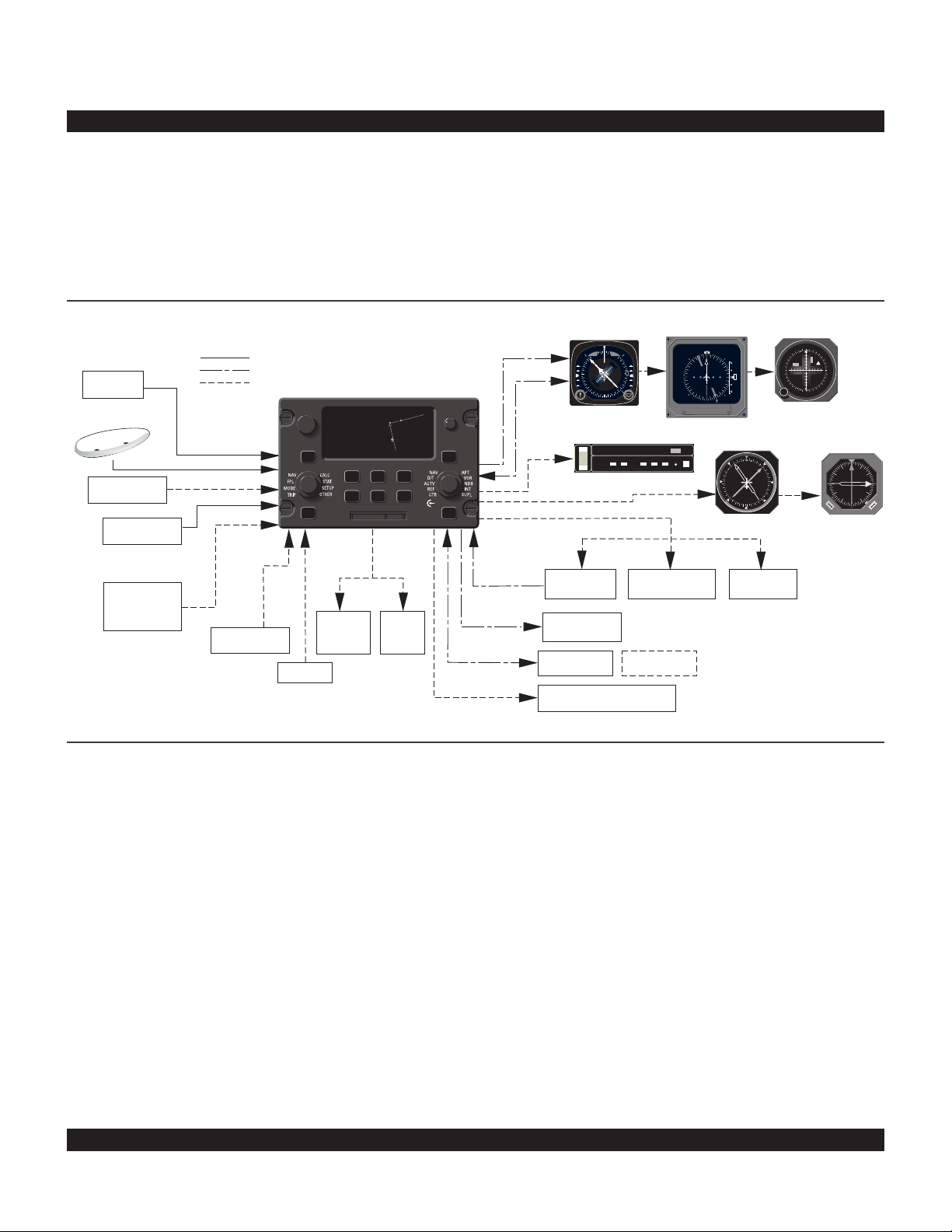
Additional system components may be added or interfaced to the KLN 900 which increase its features and
capabilities. Some of these optional components include
an external course deviation indicator (CDI) or HSI, RMI,
fuel management system, air data system, ARTEX ELS10 emergency locator transmitter (ELT), autopilot, and
external annunciators.
Rev 2
CHAPTER 1 - KLN 900 SYSTEM COMPONENTS
The KLN 900 DZUS mounted unit contains the GPS sensor, the navigation computer, a CRT display, and all controls required to operate the unit. It also houses the data
base card which plugs directly into the front of the unit.
The database card is an electronic memory containing a
vast amount of information on airports, navaids, intersections, special use airspace, and other items of value to
the pilot. The database is designed to be easily updated
by the user by using a laptop computer and Honeywell
furnished 3.5 inch diskettes or a database file that has
been downloaded from the Honeywell Internet site. The
database may also be updated by removing the obsolete
PCMCIA database card and replacing it with a current
one.
KLN 900 SYSTEM
REQUIRED FOR ALL INSTALLATIONS
AIRCRAFT
POWER
KA 92
BARO
SETTING
ALTITUDE
COMPATIBLE
MANAGEMENT
18/33V
DC
GRAY CODE
FUEL
SYSTEM
REQUIRED FOR ALL IFR APPROACH INSTALLATIONS
OPTIONAL
ı
4.7 oq
LAX18 |
LAX18
arm-«}|
159 uv
.32NM=|
ûü161^|
†ü170^|5
CRSR
D>CLR ENT
OBS ALT NRST
or DC
RS 232
RS 232
DC, PULSE, FREQ.
ARINC 429 ,
HEADING
RS 232 INPUT
MOVING
ARINC 429/419 or
DISPLAYS
RS 232
MAP
AIR DATA
FITON
ARTEX
ELS-10
GPS
BRT
CRSR
PULL SCAN
SAVMSG
PUSH
CSDB
SELECTED
COURSE
COURSE
SELECTED
LEFT/RIGHT D-BAR
ARINC 561/568
or KING SERIAL DME
COMPATIBLE
EFIS SYSTEM
WPT ALERT
MESSAGE
GPS APR GPS CRS
ALTITUDE ALERT AUDIO
HSI
OR OR
NAV HD
N
3
GG
6
E
W
S
ı
KI 525A
AUTOPILOT
ALT HDG NAV APR APGS
YD
DN
KAP 150
ALT HDG NAV APR BC
UP
RN RC PC
ı
WEATHER RADAR
REMOTE ANNUNCIATORS
BC
TRIM
TEST
RT 1401B
EHSI
ı
A
M
L
S
N
12.6
359
11.5
N
3
33
6
30
E
W
12
24
15
21
S
ADF 2
EHI 40/50
AP
ENG
W
2
2
KI 229
REMOTE SWITCH/
ANNUNCIATORS
G
RMI
3
3
N
A
D
F
S
1
1
ı
DISTANCE
DISPLAY
3
6
E
3
W
2
OB
OR
CDI
N
3
G
2
S
ı
KI 206
N
3
6
T
1
F
1
E
W
A
D
NAV NAV
KNI 582
N
E
A
D
S
B

1-2
Among the GPS Antennas that can be used with the KLN
900 are the KA 91 and KA 92. They are “patch” antennas
designed to always be mounted on the top of the aircraft.
The KLN 900 has analog outputs to drive the left-right
deviation bar of most mechanical CDIs and HSIs. In
addition, it has digital outputs to automatically drive the
course pointer and display flight plan waypoints on the
Bendix/King EHI 40 and EHI 50 electronic HSIs.
The Bendix/King KI 229 and KNI 582 RMIs may be interfaced to the KLN 900 to provide a display of magnetic
bearing to the waypoint.
The NAV mode of the Bendix/King KFC 150, KAP 150,
KAP 150H, KAP 100, KFC 200, KAP 200, KFC 250, KFC
275, KFC 300, KFC 325, KFC 400 and KFC 500 Flight
Control Systems may be coupled to the KLN 900. Many
other autopilots may also be coupled to the KLN 900.
Actual autopilot performance and capability when coupled
to the KLN 900 may vary significantly from one autopilot
model to another. Flight Control Systems utilizing either
digital or analog roll steering signals are supported.
Certain Digiflo™ and Miniflo™ fuel management systems
manufactured by Shadin Co. Inc. as well as certain fuel
computers manufactured by ARNAV Systems, Inc. and
Gebe Instruments interface with the KLN 900. These
interfaces allow the pilot to view fuel related parameters
calculated by the KLN 900 such as how much fuel will be
remaining when the aircraft lands at the destination. With
certain Shadin fuel management systems it is possible to
update the fuel on board through the KLN 900. In these
cases a separate panel mounted interface to the fuel
management computer is not required.
Compatible air data systems are available from
Bendix/King and Shadin Co. An air data system is capable of providing the KLN 900 with true air speed data
which is used for wind determination. Heading data from
the Bendix/King KCS 55A and some other compass systems maybe input directly into the KLN 900 for wind calculations to be fully automatic.
Altitude may be provided to the KLN 900 from an encoding altimeter or blind encoder, (either Gillham or DC altitude) or one of the air data computers mentioned above.
Altitude is used as an aid in position determination when
an insufficient number of satellites are in view. Altitude is
also used in several altitude related features such as
three dimensional special use airspace alerting, height
above airport, and altitude alerting.
Some installations may require remote annunciators to be
mounted in the aircraft panel in order to indicate the status of certain KLN 900 functions. Specifically, the KLN
900 has outputs to provide annunciation for waypoint alert
and message. The KLN 900 will also interface with
Bendix/King distance indicators with King DME serial bus
or indicators using ARINC 561/568 data bus.
In installations where the KLN 900 will be used for
approaches, the installations are more complicated. An
external switch/announciator is required to indicate the
approach made. Selected course is generally required to
be provided to the KLN 900 through an HSI, CDI or EFIS.
Rev 2
KA 92 GPS Antenna

2-1
Rev 2
One reason the KLN 900 is such a powerful navigation
system is because of its extensive database. A database
is an area of electronic memory used to store a large catalog of navigational and aeronautical information.
2.1 FUNCTIONS OF THE DATABASE
The database provides two primary functions. First, it
makes pilot interface with the GPS sensor much easier.
Rather than having to manually look up and then enter
the latitude and longitude for a specific waypoint, it allows
you to merely enter a simple waypoint identifier. The
database automatically looks up and displays the latitude
and longitude associated with the identifier. It’s obvious
that the database saves a lot of tedious latitude/longitude
entry and also greatly reduces the potential for data input
mistakes.
The second function of the database is that it serves as a
very convenient means to store and easily access a vast
amount of aeronautical information. Want to know the
tower frequency or the length of the runways at a specific
airport? No need to look them up in a book - just turn a
couple knobs and display the information right on the KLN
900.
2.2 DATABASE COVERAGE AREAS AND CONTENTS
The International Civil Aviation Organization (ICAO) and
Aeronautical Radio, Inc. (ARINC) break the world into the
ten geographic regions shown in figure 2-1.
The KLN 900 Americas data base contains aeronautical
information for the group of ICAO regions consisting of
Canada, USA, Latin America, and South America. The
KLN 900 Atlantic data base provides information for the
ICAO regions Europe, Africa, East Europe, and Mid East.
Likewise, the Pacific data base contains information for
East Europe, Mid East, Pacific, and South Pacific. The
databases for the KLN 900 have a primary and a secondary coverage area. The primary coverage areas are
indicated in figure 2-1 and contain more detailed information. The secondary area contains less detailed information for the rest of the world.
CHAPTER 2 - DATABASE
Figure 2-1. KLN 900 Database Geographical Regions
NOTE: Previous database versions included an “International” coverage region that included both the
Pacific and the At lantic regions. Due to space constraints, the “International” version has been discontinued.
75°
60°
CANADA
EUROPE
75°
EAST EUR
60°
45°
30°
15°
0°
15°
30°
45°
60°
PACIFIC
SOUTH PAC
165°150°135° 120°105° 90° 75° 60° 45° 30° 15° 0° 15° 30° 45° 60° 75° 90° 105°120°135°150°165°180°
Americas Data Base
coverage area
USA
LATIN AM
SOUTH AM
Atlantic Data Base
coverage area
AFRICA
Pacific Data Base
coverage area
MID EAST
PACIFIC
SOUTH PAC
Overlap in Pacific & Atlantic
Data Base coverage areas
45°
30°
15°
0°
15°
30°
45°
60°

2-2
Rev 2
Specifically, all databases contain complete information
for all worldwide VORs, NDBs, and minimum safe altitudes (MSAs). For its primary area, the database contains public use and military airports which have any runway at least 1000 feet in length. For its secondary area,
the database also contains airports having a hard surface
runway at least 3000 feet in length. Airport communication frequencies and runway information are provided
only for airports in the primary area of the database.
Intersections, air route traffic control center data, flight
service station frequencies, and special use airspace are
also provided only for the primary area.
The following is a list of the KLN 900 database contents:
*AIRPORTS
• Identifier
• Name
• City, State or Country
• Type (public, private, military, or heliport)
• Latitude and Longitude
• Elevation
• Approach indicator for precision, non-precision or no
instrument approach at airport
• Radar approach/departure environment indicator
• Whether airport underlies CL B, TRSA, CL C, CTA, or
TMA
• Time relative to UTC (Zulu)
• Communication frequencies (VHF and HF):
ATIS
Clearance delivery
Tower
Ground control
Unicom
Multicom
Approach (IFR)
Departure (IFR)
Class B, Class C, TRSA, CTA, TMA (VFR)
Center (when used for approach)
Arrival
Radar
Director
Radio
ASOS (automatic surface observation system)
AWOS (automatic weather observing station)
AAS (aeronautical advisory service)
ATF (Aerodrome traffic frequency)
CTAF (common traffic advisory frequency)
MF (mandatory frequency)
Ramp control
PCL (pilot-controlled lights)
• Runway data (designation, length, surface, lighting,
traffic pattern direction)
• Airport Services (fuel, oxygen, customs, indicator for
presence of a landing fee)
• Airport Comments (user may manually enter remarks
of up to 33 characters at any 100 airports in database)
VORs
• Identifier
• Name
• Frequency
• DME indicator
• Class (high altitude, low altitude, terminal, undefined)
• Latitude, Longitude, and Magnetic variation
NDBs
• Identifier
• Name
• Frequency
• Latitude and Longitude
(Note - Outer Compass Locators are stored as
Intersections)
*INTERSECTIONS (low altitude, high altitude, SID/STAR,
approach, and outer markers)
• Identifier
• Latitude and Longitude
*SID/STAR/Approach Procedures
• All compatible pilot-nav SID/STAR procedures
• Non-precision approaches (except localizer, LDA
(Localizer Directional Aid), SDF (Simplified Directional
Facility)) approved for overlay use. Includes all public
GPS only approaches.
MISCELLANEOUS
• *Air Route Traffic Control Center (ARTCCs and FIRs)
name, boundaries and frequencies (VHF and HF)
• *Flight Service Stations (Location of points of
communication and associated frequencies - VHF
and HF), VOR used.
• Minimum Safe Altitudes
• *Special Use Airspace name and boundaries, lateral
and vertical, (Prohibited, Restricted, Warning, Alert,
MOA, Class B, TRSA, Class C, CTA, TMA)
1000 USER DEFINED WAYPOINTS
(250 waypoints for ORS 01 units)
• Identifier
• Latitude and Longitude
• Additional data depending on how user defines
waypoint:
User airports (elevation & surface of longest runway)
User VOR (frequency and magnetic variation)
User NDB (frequency)
And you think your telephone directory has a lot of
information!
* Items indicated with asterisk are included in the primary
database coverage area, but not in secondary coverage
area. The exception is that airports in primary coverage
area include those public and military bases having a runway at least 1000 feet in length. Airports in secondary
coverage area are those having a hard surface runway at
least 3000 feet in length.

2-3
Rev 2
2.3 USE OF ICAO IDENTIFIERS
Waypoints are stored in the KLN 900 database almost
exclusively by their ICAO identifiers. ICAO is an internationally accepted reference for the data. In almost all
cases the proper ICAO identifiers may be taken directly
from Jeppesen Sanderson or government aeronautical
charts. For example, Dallas and Los Angeles VORs have
the familiar ICAO identifiers DFW and LAX, respectively.
Please note that one area of potential confusion is airport
identifiers in the Continental United States, Alaska, and
Canada. Many airport identifiers in the database have
four letters beginning with a prefix letter that corresponds
to the geographic area in which it is located. The prefix
letter for the Continental United States is “K”. Thus, the
identifier for Dallas/Fort Worth International airport is
KDFW, not DFW. This distinguishes the airport identifier
from the VOR identifier. Likewise, the identifier for Los
Angeles International airport is KLAX while the VOR identifier is LAX. The prefix letter for Alaska is “P” and for
Canada is “C”.
NOTE: There are several exceptions in Alaska. In many
cases, airports with three letter identifiers receive the
prefix “P”, but there are many that don’t. The most reliable
method of determining an Alaska airport identifier is to
look it up from the airport name or city. See section 3.7.4,
“Selecting Waypoints by Name or CIty”.
Not all airport identifiers receive the prefix letter. Airport
identifiers which are combinations of letters and numbers
do not receive the prefix letter. Examples of airport identifiers not using the prefix are 3C2, 7TX6, and M33.
So remember, if you are entering or looking for an
airport identifier that is all letters (no numbers) then it
will begin with a “K” prefix in the Continental U.S., a
“P” in Alaska, or a “C” in Canada. If there are numbers in the identifier then a prefix is not used. For
other areas of the world the airport identifier stored in
the KLN 900 database is identical to how it is charted.
2.4 UPDATING THE DATABASE
The information stored in the database would eventually
become obsolete if there wasn’t some means to update it.
For example, navaids can move or change frequency,
new runways can be added to an airport, communication
frequencies can change, and on and on.
The database is housed in a PCMCIA card which plugs
directly into the front of the KLN 900. It is designed so
that there are two ways for the user to easily keep the
database current. The first is to electronically update the
database by means of a personal computer and a database file that has been downloaded from the Honeywell
Internet site or supplied by Honeywell on 3.5” diskettes. A
jack, mounted on the front of the KLN900, provides a
means of interfacing the KLN 900 with the computer via
an interface cable.
The second method of database update is to remove the
old card and insert a current card. This method involves
returning the old card to Honeywell.
Every 28 days, Honeywell receives new Nav Data™
information from Jeppesen Sanderson. This information
is processed and both installed on the Honeywell Internet
site and downloaded onto diskettes and database cards.
Honeywell makes these types of update services available to you in a choice of several subscription or random
update programs. See section 2.8 of this manual for
details on these programs.
Regardless of whether the computer method or the card
exchange method of database updating is used,
Honeywell sends the update so that it arrives prior to the
next effective date. The new update may be installed any
time prior to the effective date and the KLN 900 will use
the previous data up to the effective date and automatically begin using the new data on the effective date.
In order to get maximum utilization from the KLN 900,
Honeywell highly encourages you to update the database
on a frequent basis, if not every 28 days. It is also a matter of safety to not fly with out-of-date information.
WARNING: The accuracy of the database information is only assured if it is used before the end of the
effectivity period. Use of out-of-date database information is done entirely at the user’s own risk.

2-4
Rev 2
2.4.1 Computer Updating Of The Database
Update information is downloaded from the Honeywell
Internet site or sent to you on several 3.5” disks. In order
to use this update method you must have access to an
IBM compatible computer having a disk drive capable of
using and booting (loading) from 3.5” 1.44 megabyte high
density disks (when using 3.5” disks). This computer also
needs to have an available COM 1 or COM 2 serial port.
In addition, an interface cable that plugs into both the
computer and into the data loader jack on the front of the
KLN900 is required.
NOTE: Instructions for ordering the PC Data Loader Kit
(which includes the PC interface cable) appear in the
appendix on page F-3.
CAUTION: The database must be updated only while
the aircraft is on the ground. The KLN 900 does not
perform any navigation functions while the database
is being updated. Since a database update takes
approximately 10 minutes it is a good idea to turn off
all electrical equipment on the aircraft except for the
KLN 900 to avoid running down the aircraft battery.
NOTE: 3.5” disks can only be used to update one KLN
900, although they can update this specific unit numerous
times. The first time the disks are used in an update
operation, a unique identification code from the KLN 900
being used is uploaded to the disks. These disks may be
used in this specific KLN 900 an unlimited number of
times which could be required if you switch back and forth
between the Americas, Pacific, and Atlantic data bases
during one update cycle. These disks may not, however,
be used to update other KLN 900s. Similarly, a unique
identification code is encrypted into all database updates
downloaded from the Honeywell Internet site.
Follow these steps to update the KLN 900:
1. Plug the 9-pin female connector end of the interface
cable into a COM serial port of the computer. If the computer has COM 1 and COM 2 serial ports, either may be
used. Some computers use a 9-pin COM serial port connector while other computers use a 25-pin connector. If
the computer being used has a 9-pin connector, the interface cable connector will plug directly into the computer’s
9-pin connector. If the computer’s COM serial port uses a
25-pin connector, use a 25-pin to 9-pin adapter to adapt
the interface cable’s connector to the computer’s connector.
2. Plug the other end of the interface cable (4 conductor
male plug) into the data loader jack on the front of the
KLN 900.
NOTE: The interface cable needs to be firmly pushed into
the jack.

2-5
Rev 2
3. When updating from the Internet, download the compressed file from the Honeywell www.gpsdatabase.com
Internet site following the instructions available at the site.
Then, execute Netload.exe from a DOS prompt (not a
DOS window running under Windows). The computer
screen will display “Ready” when the computer is ready to
continue with the database update operation.
4. When updating from diskettes, insert Disk 1 into the
computer’s disk drive. There can be either 2 or 3 disks
used for the update so be sure the label on the outside of
the disk says “Disk 1 of 2” or “Disk 1 of 3”. Turn on the
PC and the program on the disk will automatically “boot”
(load). The computer screen will display “Ready” when
the computer is ready to continue with the database
update operation.
5. Turn on the KLN 900. Press E as required to
approve the Self Test and Database pages. Use the left
outer knob to select the Setup (SET) type pages and the
left inner knob to select the SET 0 page (figure 2-2).
NOTE: The Database Access Key is used for updating
the database. The Access Key must be provided before
downloading a database file from the Internet.
6. Press the left C. UPDATE PUBLISHED DB will
now be displayed as in figure 2-3.
7. Press E. The database region and the expiration
date of the database presently loaded in the KLN 900 is
displayed (figure 2-4). If the database is out-of-date the
word EXPIRES changes to EXPIRED.
8. Press E to acknowledge the information on this
page and to continue the update procedure. The estimated load time in minutes is now displayed (figure 2-5).
Figure 2-2
Figure 2-3
Figure 2-4
Figure 2-5
U P D A T E
D A T A B A S E
O N G R O U N D
O N L Y
KEY XXXXXXXXX
SET 0
U P D A T E
D A T A B A S E
UPDATE PUBLISHED DB
CRSR ent
U P D A T E
AMERICAS
DATA BASE EXPIRES
15 AUG 99
U P D A T E ?
CRSR ent
U P D A T E
D A T A B A S E
E S T . L O A D
T I M E : 6 MIN
A P P R O V E ?
CRSR ent

2-6
Rev 2
NOTE: In steps 6, 7, and 8, repeated presses of F will
terminate the update process and bring the display back
to the original SET 0 page shown in figure 2-2.
9. Press E to acknowledge the estimated load time
and begin erasing the existing database. The unit will
now display ERASING DATA BASE (figure 2-6). After
the database has been erased, loading of the new data
begins automatically. As the new data is being loaded,
the percentage of transfer is displayed (figure 2-7).
10. Monitor the computer screen. When updating from
disks, the computer screen will display “Insert Disk 2 then
press any key to continue” when the first disk has been
loaded. Disk 1 should now be removed from the disk
drive and disk 2 should be inserted. Press any key on the
computer. The load operation will continue. If there are 3
disks the computer screen will tell you when to insert
disk 3.
11. The KLN 900 will indicate when the database update
is complete as shown in figure 2-8. The computer screen
will display the new database expiration date. You may
either turn the KLN 900 off at this point or press E to
restart the KLN 900.
12. Remove the interface cable. Turn off the computer.
The chances are small of having difficulty updating the
database but if you have a problem:
First check that the interface cable is properly connected
and that the computer is turned on. Ensure that the interface cable is firmly inserted into the jack on the front of
the KLN900. If there is a problem with the connection or
the computer the KLN 900 will display LOADER NOT
READY. When the problem is corrected this prompt is
removed and the update operation can continue from
where it left off.
If the wrong disk is inserted the computer screen will display “Incorrect Disk - please insert disk __” where the
number 2 or 3 is inserted in the blank.
If an internal test fails after the data has been loaded, the
KLN 900 will display CHECKSUM ERROR, DATA BASE
INVALID, ACKNOWLEDGE?. Press E to acknowledge. The KLN 900 will then display RETRY and EXIT.
Use the left outer knob to position the cursor over the
desired choice and press E.
There are other error messages that may be displayed. If
you have a problem that you can’t resolve, write down
any error messages to aid your Bendix/King Service
Center in identifying the problem.
Figure 2-6
Figure 2-7
Figure 2-8
U P D A T E
D A T A B A S E
E R A S I N G
D A T A B A S E
SET 0
U P D A T E
D A T A B A S E
14 PERCENT COMPLETE
SET 0
U P D A T E
D A T A B A S E
UPDATE PUBLISHED DB
COMPLETED
ACKNOWLEDGE?
CRSR ent
2-7
Rev 2
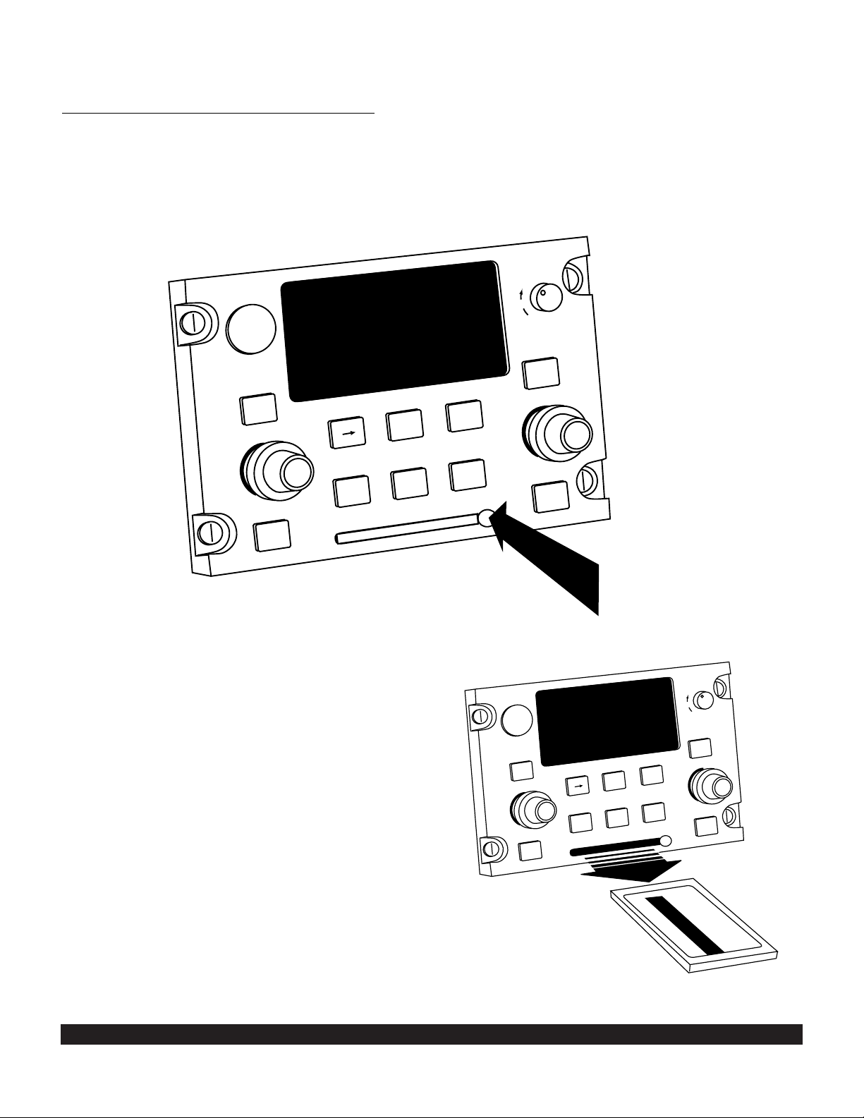
2. Remove the new database card from its shipping
container. Note that the label on the card indicates which
side is up and which end to insert into the KLN 900.
Insert the new card into the front of the unit. When the
card is properly inserted, the card is flush with the front of
the KLN 900.
3. The container which was used to ship the new card
to you is used to return the old card back to Honeywell. A
return shipping label is included in the container.
Remove the backing from the label and place it in the
address position of the shipping container.
4. Insert the old card into the container. Peel off the
protective backing from the adhesive on the end flap of
the container. Press the flap against the adhesive to seal
the container.
5. Please return the old card promptly by mailing immediately at any mailbox. No postage is required if mailed
from within the U.S. Users will be billed for cards not
returned and no additional cards will be sent until either
the old card or payment for the old card is received.
Figure 2-9
2.4.2 Card Exchange Updating of the Database
1. To exchange the KLN 900’s database card simply
turn the unit power off and remove the card from the front
of the unit. This is accomplished by depressing the ejection button on the right side of the card (figure 2-9) and
then pulling the card straight out of the front of the KLN
900. (figure 2-10)
Figure 2-10
BRT
OFF
CRSR
CRSR
D
NAV
FPL
MODE
TRIP
MSG
OBS
CLR
ALT
ENT
NRST
NAV
ACTV
NAV
FPL
MODE
TRIP
DT
REF
CTR
PULL SCAN
CRSR
MSG
SAVE
BRT
OFF
CRSR
NAV
ENT
NRST
ACTV
DT
REF
CTR
PULL SCAN
SAVE
CLR
D
ALT
OBS
A

2-8
Rev 2
2.5 USER DEFINED DATABASE
In addition to the published database of airports, VORs,
NDBs, and intersections stored in the card, you may create up to 1000 other waypoints (250 waypoints for ORS
01 units). These waypoints may be designated by you to
be one of the four waypoint types above or as a waypoint
not falling into one of these types. In the latter case the
waypoint is called a Supplemental waypoint. Section 5.4
describes how you create a user-defined waypoint.
2.6 UPDATING USER DEFINED WAYPOINTS AND FLIGHT PLANS
In addition to being able to create and modify userdefined waypoints and flight plans using the KLN 900, the
unit also supports the ability to upload and download this
information to a PC via the same serial data link and
cable used for updating the database. The PreFlight software program (described in appendix F) allows you to
transfer data between your computer and your KLN 900.
Thus, flight plans and waypoints can be downloaded to a
PC where PreFlight’s Flight Plan Editor can be used to
modify the data. Better yet, some of the leading manufacturers of PC-based flight planning programs, such as
Jeppesen’s MentorPlus FliteMap and Delta Technology
International’s Destination Direct, have developed versions of their programs that can be used to create flight
plans and user-defined waypoints for the KLN 900. Now,
you’ll be able to create your flight plans wherever and
whenever you want to.
NOTE: The ability to update user-defined waypoints and
flight plans applies only to ORS 02 or later units.
User-defined waypoints and flight plans can also be
copied to and from the database card which plugs into the
front of the KLN 900. This capability, along with the ability
to download this information from a PC, allows an operator to readily load a set of standard flight plans and user
waypoints into a fleet of aircraft.
2.6.1 Computer Updating of User Data
Copying user data via a PC requires the Honeywell
PreFlight software in addition to the hardware used for
computer updating of the database listed in section 2.4.1.
The PreFlight software is a Windows application.
CAUTION: The user data must be updated only while
the aircraft is on the ground. The KLN 900 does not
perform any navigation functions while the user data
is being updated.
Follow these steps to copy the KLN 900 user data:
1. Connect the hardware following the steps in paragraphs 1 and 2 of section 2.4.1.

2-9
2. Follow the instructions in the PreFlight User’s Manual
to install and run the transfer program on a Microsoft
Windows compatible personal computer. Then, select
the “Data Transfer” button on PreFlight’s main menu.
3. Turn on the KLN 900. Press E as required to
approve the Self Test and Database pages. Use the left
outer knob to select the Setup (SET) type pages and the
left inner knob to select the SET 10 page (figure 2-11).
NOTE: If the groundspeed exceeds thirty knots, user data
copy won’t be allowed and the SET 10 page will be displayed as in figure 2-12.
4. Follow either step (a) or step (b) below:
(a) If you are copying user data from the KLN 900 to the
PC, press the “D
ownload data from GPS unit” button on
the PC and enter a filename into which the downloaded
data will be stored and press OK. Then, on the KLN 900,
press the left C. Us the left outer knob to move the
cursor over COPY UNIT TO PC? and press E.
(b) If you are copying user data from the PC to the KLN
900, press the “Upload data to GPS unit” button on the
PC and specify the name of the file which contains the
flight plan and waypoint information to be uploaded, and
press OK. Then, on the KLN 900, press the left C.
Use the left outer knob to move the cursor over COPY
PC TO UNIT? and press E.
5. The user data copy operation will begin and the screen
shown in figure 2-13 will be displayed.
6. The screen shown in figure 2-14 will be displayed upon
completion of the copy operation. Press E to acknowledge.
7. If the user data was copied from the PC to the KLN
900, the screen shown in figure 2-15 will be displayed.
The KLN 900 is reset following a transfer of user data to
the unit to enable the user data to be checked by various
functions performed during the startup sequence. Press
E to acknowledge and initiate a unit reset.
8. Remove the interface cable and turn off the computer
as desired.
If you have a problem copying the user data:
If there is a problem with the connection or the computer,
the KLN 900 will display LOADER NOT READY. First
check that the interface cable is properly connected and
that the computer is turned on. Ensure that the interface
cable is firmly inserted into the jack on the front of the
KLN 900. Pressing E will cancel the copy operation
and return to the initial SET 10 page.
If you have a problem that you can’t resolve, write down
any error messages to aid your Bendix/King Service
Center in identifying the problem.
Rev 2
Figure 2-11
Figure 2-15
Figure 2-14
Figure 2-13
Figure 2-12
USER DATA COPY
COPY UNIT TO DB CARD?
COPY DB CARD TO UNIT?
COPY UNIT TO PC?
COPY PC TO UNIT?
SET10
C O P Y
U S E R D A T A
O N G R O U N D
O N L Y
SET10
USER DATA COPY
IN PROGRESS...
SET10
USER DATA HAS BEEN
SUCCESSFULLY
COPIED
ACKNOWLEDGE?
SET10
KLN 900 WILL RESET
ITSELF TO USE NEW
USER DATA.
ACKNOWLEDGE?
SET10

to copy the user data from the unit to the card, the
KLN 900 will display DATA BASE CARD IS WRITE
PROTECTED. COPY OPERATION IS CANCELED. In
either of these cases, pressing E will cancel the copy
operation and return to the initial SET 10 page.
Before copying data from the database card to the KLN
900, a checksum is calculated on the source data. If a
checksum error is detected, the KLN 900 will display
USER DATA ON DB CARD OR PC IS BAD. COPY
OPERATION IS CANCELED. Pressing E will cancel
the copy operation and return to the initial SET 10 page.
If you have a problem that you can’t resolve, write down
any error messages to aid your Bendix/King Service
Center in identifying the problem.
2.7 INTERNAL MEMORY BACKUP BATTERY
The KLN 900 contains an internal lithium battery that is
used to “keep-alive” the user-defined database as well as
flight plans. This battery has a typical life of three to five
years. It is highly recommended that the battery be
replaced every three years at an authorized Bendix/King
Service Center.
2.8 DATABASE UPDATE SERVICE OPTIONS
The following tear-out pages can be used for ordering the
Americas, Pacific, and Atlantic database update services
from Honeywell. The forms may be mailed or faxed for
your convenience.
2-10
2.6.2 Card Updating of User Data
Copying user data to or from a database card does not
require any hardware other than the KLN 900 and the
database card. A database card that is programmed with
a regular database can be used without changing the
database contents.
CAUTION: The user data must be updated only while
the aircraft is on the ground. The KLN 900 does not
perform any navigation functions while the user data
is being updated.
Follow these steps to copy the KLN 900 user data:
1. If user data is to be copied from a database card to the
KLN 900, turn the unit power off; remove any installed
database card as required; and insert the database card
containing the user data to be copied into the front of the
unit. (Refer to section 2.4.2 for more details on removing
and installing datacards.)
2. Turn on the KLN 900. Press E as required to
approve the Self Test and Database pages. Use the left
outer knob to select the Setup (SET) type pages and the
left inner knob to select the SET 10 page (figure 2-11).
NOTE: If the groundspeed exceeds thirty knots, user data
copy won’t be allowed and the SET 10 page will be displayed as in figure 2-12.
3. Press the left C. Use the left outer knob to move the
cursor over the COPY UNIT TO DB CARD? or COPY DB
CARD TO UNIT? line as appropriate.
4. Press E. The user data copy operation will begin
and the screen shown in figure 2-13 will be displayed.
5. The screen shown in figure 2-14 will be displayed upon
completion of the copy operation. Press E to acknowledge.
6. If the user data was copied from the database card to
the unit, the screen shown in figure 2-15 will be displayed.
The KLN 900 is reset following a transfer of user data to
the unit to enable the user data to be checked by various
functions performed during the startup sequence. Note
that the active flight plan 0 will be erased upon unit reset if
the installed database card does not contain a normal
database. Press E to acknowledge and initiate a unit
reset.
If you have a problem copying the user data:
If the database card is not properly installed in the KLN
900, the unit will display DATA BASE CARD NOT PRE-
SENT. If the database card is write protected while trying
Rev 2

Name:
Company:
Address:
City:
State: Zip Code:
Country:
Telephone: ( )
FAX: ( )
E-mail:
Aircraft Make:
Aircraft Model: ______
Please set up the service under:
MasterCard, VISA, Discover, or
American Express
Method of Payment
Check/Money order enclosed
Wire Transfer:
Chase Manhattan Bank, NY
Acct #910-2-538734
Customer Number: ___________
Please contact us if you do not have a customer number. (Note: Your customer number is
the first six digits of your sales order number.)
Include applicable sales tax for your state.
Number
Expires
Signature
Honeywell offers several update service
options to suit your requirements. Please
select the service desired, then fill out and
mail this order form. Credit card orders
may be faxed.
Updates from the Internet can be obtained
directly by logging onto the Honeywell
www
.gpsdatabase.com Internet site and
following the instructions provided, or by
calling the telephone number below to set
up an account.
Note: Updates are current for 28 days after
effective date on diskette. If you select any
service other than the complete 13-time
service, your KLN 900 will begin alerting
you after 28 days that your data base is
out-of-date.
Send to:
Honeywell International Inc.
Navigation Services
Mail Drop #66
23500 West 105th Street
Olathe, KS 66061
U.S.A.
Tel: (800) 247-0230 (U.S. Callers)
(913) 712-3145 (International)
FAX: (913) 712-3904
email: nav.database@Honeywell.com
web site: www.gpsdatabase.com
Check One:
Complete Update Service.
Provides 13 updates–one every 28
days for one year.
Six-time Update Service.
Provides six updates–one every 56
days for one year.
Four-time Update Service.
Provides four updates–one during
each quarter for one year.
Single Update. Provides one
update upon receipt of order.
Check Requested Data Base:
Americas Data Base
Pacific Data Base
Atlantic Data Base
Check One:
Database Card Format
(available in U.S./Canada only)
Diskette Format
(Laptop Computer Required. See
section 2 of KLN 900 Pilot’s Guide
for details.)
KLN 900 Data Base Update Service Order Form
Consult Pricing Sheet (006-08794-0006) for Service Prices
N

BUSINESS REPLY MAIL
FIRST-CLASS MAIL PERMIT NO. 121 OLATHE, KANSAS
POSTAGE WILL BE PAID BY ADDRESSEE
Fold here
NO POSTAGE
NECESSARY
IF MAILED
IN THE
UNITED STATES
HONEYWELL INTERNATIONAL INC.
Navigation Services, Mail Drop #66
23500 West 105th Street
P.O. Box 1950
Olathe, KS 66051-9930
Tape here

3-1
Rev 1
In this chapter you will learn the basic operation of the
front panel controls and then how to perform Direct To
navigation (navigating from your present position direct to
your desired location).
CHAPTER 3 - LEVEL 1 OPERATION
Figure 3-1 KLN 900 Navigation Coverage Area
3.1 COVERAGE AREA
The KLN 900 was designed to provide worldwide navigation coverage from North 74° latitude to South 60° latitude
(figure 3-1). Outside this area, magnetic variation must
be manually entered as discussed in section 5.12. See
section 2.2 for the database coverage areas.
IMPORTANT: Special installation procedures must be followed in order for the KLN 900 to be certified for IFR use.
Consult the KLN 900 Flight Manual Supplement for the operating limitations of this unit.
74°
60°
45°
30°
74°
60°
45°
30°
15°
0°
15°
30°
45°
60°
15°
15°
30°
45°
60°
0°

KLN 900 CONTROLS
Figure 3-2
3-2
ı
POWER/BRIGHTNESS
LEFT
CURSOR
LEFT
INNER
KNOB
LEFT
OUTER
KNOB
4.7 oq
LAX18 |
arm-«}|
159 uv
.32NM=|
ûü161^|
†ü170^|5
CRSR
MESSAGE DIRECT
TO
LAX18
D CLR ENT
OBS ALT NRST
OBS/LEG
MODE
SELECTOR
CLEAR
ALTITUDE
ENTER
NEAREST
FITON
AIRPORT
GPS
BRT
CRSR
PULL SCAN
SAVEMSG
SAVE
PUSH
ON
RIGHT
CURSOR
RIGHT
INNER
KNOB
RIGHT
OUTER
KNOB

3-3
Rev 2
3.2 TURN-ON AND SELF TEST
Enough of the preliminaries. Let’s get started into actually turning the KLN 900 on and using it! Figure 3-2 will
fold out and allow you to use it as a reference as you read
this chapter, especially if you don’t have a KLN 900
immediately at hand. The steps below take a lot of words
to explain, but you will find that in actual use you will
accomplish these steps in just a few moments.
NOTE: When power is applied to the KLN 900 it always
“wakes up” in the Enroute-Leg mode. Only the EnrouteLeg mode is described in this chapter. In this mode the
KLN 900 performs great circle navigation (the shortest
distance between two points located on the earth’s surface). The course deviation output displayed on the unit’s
internal course deviation indicator (CDI) and provided to
an external HSI or CDI is five nautical miles left and right,
full-scale sensitivity. The other modes of the unit are
described in section 5.9, chapter 6, and chapter 9.
1. Turn-on the KLN 900 by pressing the power/brightness knob to the “in” position. The power/brightness
knob is located on the upper right side of the unit. It
takes just a few seconds for the screen to warm up.
2. The Turn-On page will be displayed for a few seconds (figure 3-3). During this time the KLN 900 performs an extensive internal test. The ORS
(Operational Revision Status) level number in the
upper right corner of the display should match one of
the ORS levels indicated on the first page of this
Pilot’s Guide. If desired, you may program four lines
of personalized information (such as your name, the
type of aircraft, and your aircraft’s identification number) which is displayed each time the Turn-On page
is in view. The procedure for doing this is described
in section 5.7.
When the internal test is complete, the Turn-On page
will automatically be replaced by the Self Test page
(figure 3-4). NOTE: if the KLN 900 is being operated
without an external configuration module, the
Configuration Module page (figure 3-5) will be displayed. Simply press E to acknowledge and proceed. If the KLN 900 is operating in the take-home
mode, the Take-Home Warning page (figure 3-6) is
displayed and must be acknowledged by pressing
E. See section 5.14 for more information on the
Take-Home mode.
NOTE: The IFR/VFR selection shown in figure 3-6 is
available on ORS 04 and later versions of the KLN 900.
If desired, the IFR/VFR selection allows you to temporarily configure the KLN 900 for IFR APR (Approach), IFR
ENR (En route), or VFR operations.
Figure 3-3
Figure 3-4
Figure 3-5
Figure 3-6
GPS ORS 04
c1998 ALLIEDSIGNAL INC
SELF TEST IN PROGRESS
DIS 34.5NM|DATE/TIME
+++++j+‚⁄++| 31 JUL 99
OBS IN 242^|08:10:03CST
OUT 315^|ALT 1100ft
RMI 130^|BARO:29.92"
ANNUN ON| APPROVE?
enr-leg CRSR
EXTERNAL CONFIGURATION
MODULE NOT PRESENT.
ACKNOWLEDGE?
WARNING:
SYSTEM IS IN TAKE HOME MODE: DO NOT
USE FOR NAVIGATION
IFR/VFR: IFR APR
ACKNOWLEDGE?
enr-leg ent
Loading...