

Page 1
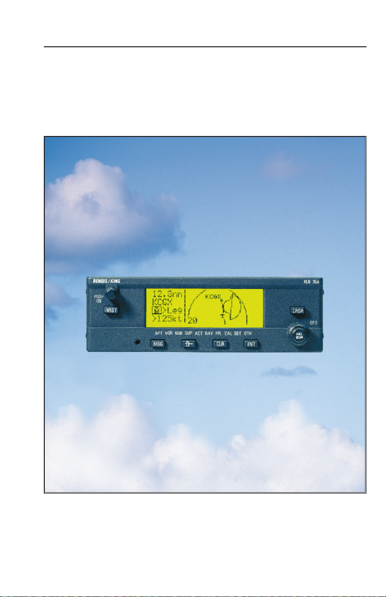
Pilot’s Guide
KLN 35A
Bendix/King
Global Positioning System
®
ORS 01
A
Page 2

WARNING
Information subject to the export control laws. This document, which includes
any attachments and exhibits hereto, contains information subject to
International Traffic in Arms Regulation (ITAR) or Export Administration
Regulation (EAR) of 1979, which may not be exported, released or disclosed
to foreign nationals inside or outside the U.S. without first obtaining an export
license. Violators of ITAR or EAR may be subject to a penalty of 10 years
imprisonment and a fine of $1,000,000 under 22 U.S.C. 2778 or Section
2410 of the Export Administration Act of 1979. Include this notice with any
reproduced portion of this document.
COPYRIGHT NOTICE
©1996 AlliedSignal, Inc.
Reproduction of this publication or any portion thereof by any means without
the express written permission of AlliedSignal Commercial Avionics Systems
is prohibited. For further information contact the Manager, Technical
Publications; AlliedSignal Commercial Avionics Systems; 400 North Rogers
Road; Olathe, Kansas 66062. Telephone: (913) 782-0400.
Page 3

AlliedSignal, Inc.
Commercial Avionics Systems
400 North Rogers Road
Olathe, Kansas 66062-1294
FAX: 913-791-1302
TELEPHONE: 913-782-0400
006-08791-0000
Rev. 2 4/97
A
Page 4

KLN 35A Pilot’s Guide
006-08791-0000
for KLN 35A
with
Operational Re vision Status ORS 01
April 1997
Page 5

Revision History and Instructions
Manual KLN 35A Pilots Guide
Revision 2, April 1997
Part Number 006-08791-0000
Typographical and spelling errors corrected on pages; 3-27, 3-41,
3-65 and 3-67. Illustration corrections on figures; 3-184 and 4-20.
Database Form Corrections. Added warning and copyright notices
on front cover. Added revision page R-1. Deleted EFF-1 through
EFF-6 pages.
R-1
Effective Date 4/97006-08791-0000 Rev 2
Page 6

NOTE: A “whiskers” border is used around
åå.ånm ZBV
ееееее BIMINI
#>Leg N 25
VOR 1 W 79
data on some of the figures in this Pilot's Guide
to indicate that the data inside the border is
flashing.
Page 7

KLN 35A Pilot’s Guide Table of Contents
INTRODUCTION..............................................................................i
KLN 35A SNEAK PREVIEW .........................................................ii
HOW-TO INDEX ............................................................................iv
1. KLN 35A SYSTEM COMPONENTS .......................................1-1
2. DATA BASE ...........................................................................2-1
2.1. Data Basics .....................................................................2-1
2.2. Data Base Contents and Coverage Areas ......................2-1
2.3. ICAO Identifiers ...............................................................2-3
2.4. Updating the Data Base ..................................................2-4
2.5. User Defined Data Base ..................................................2-7
2.6. Data Base Update Service Options .................................2-7
3. BASIC GPS OPERATION ......................................................3-1
3.1. Coverage Area ................................................................3-1
3.2. Turn-on and Self Test ......................................................3-1
3.3. Display Format ................................................................3-7
3.4. Basic Operation of Panel Controls ................................3-10
3.4.1. Page Selection ......................................................3-10
3.4.2. Data Entry .............................................................3-12
3.4.3. The Duplicate Waypoint Page ..............................3-15
3.4.4. Cyclic Fields ..........................................................3-16
3.5. Message Page ..............................................................3-17
3.6. Initialization and Time to First Fix ..................................3-18
3.7. Selecting and Scanning Waypoints ...............................3-20
3.7.1. Selecting Waypoints by Identifier ..........................3-21
3.7.2. Selecting Waypoints by Scanning .........................3-22
3.7.4. Selecting Waypoints by Name or City ...................3-24
3.8. “Nearest” Functions ......................................................3-26
3.8.1. Viewing the Nearest Waypoints ............................3-27
3.8.1.1 Nearest Airport Criteria .................................3-28
3.8.1.2 Continuous Display of Nearest Airport ..........3-29
3.8.2. Viewing the Nearest Special Use Airspaces .........3-29
3.8.3. Viewing the Nearest Flight Service Station
Frequencies ..........................................................3-31
3.8.4. Viewing the Nearest Center Frequencies .............3-32
3.9. Direct to Operation ........................................................3-32
3.9.1. Initiating a Direct To ..............................................3-33
3.9.2. Canceling a Direct To ...........................................3-35
TOC-1
Effective Date 5/95006-08791-0000 Rev 0
Page 8

Table of Contents
3.9.3. Waypoint Alerting for Direct To Operation ............3-35
3.10. Navigation Pages ........................................................3-36
3.10.1. The Navigation 1 (NAV 1) Page ..........................3-36
3.10.2. The Navigation 2 (NAV 2) Page ..........................3-39
3.10.3. The Navigation 3 (NAV 3) Page ..........................3-40
3.10.4. The Navigation 4 (NAV 4) Page ..........................3-40
3.11. Waypoint Pages ..........................................................3-45
3.11.1. Airport Pages ......................................................3-45
3.11.1.1. The Airport 1 (APT 1) Page ........................3-45
3.11.1.2. The Airport 2 (APT 2) Page ........................3-46
3.11.1.3. The Airport 3 (APT 3) Page ........................3-47
3.11.1.4. The Airport 4 (APT 4) Page ........................3-48
3.11.1.5. The Airport 5 (APT 5) Page ........................3-50
3.11.2. VOR Pages .........................................................3-51
3.11.2.1. The VOR 1 Page ........................................3-51
3.11.2.2. The VOR 2 Page ........................................3-51
3.11.3. NDB Pages .........................................................3-52
3.11.3.1. The NDB 1 Page .........................................3-52
3.11.3.2. The NDB 2 Page .........................................3-52
3.11.4. Supplemental Waypoint Pages ...........................3-53
3.11.4.1. The Supplemental 0 (SUP 0) Page .............3-53
3.11.4.2. The Supplemental 1 (SUP 1) Page ............3-53
3.11.4.3. The Supplemental 2 (SUP 2) Page ............3-54
3.11.4.4. The Supplemental 3 (SUP 3) Page .............3-54
3.12. Viewing and Setting the Date and Time ......................3-55
3.13. The Other (OTH) Pages ..............................................3-57
3.13.1. Determining the Status of the GPS Signals ........3-57
3.13.2. Viewing and Deleting User Waypoints and
Waypoint Remarks ..........................................3-59
3.13.2.1.The OTH 3 Page ..........................................3-60
3.13.2.2. The OTH 4 Page .........................................3-61
3.13.3. Viewing the KLN 35A Software Status and
Time of Operation ...........................................3-61
3.15. Special Use Airspace Alerting .....................................3-62
3.16 Sample Trip .................................................................3-65
3.16.1 Pre-departure ......................................................3-65
3.16.2 En route ..............................................................3-66
3.16.3 Terminal Area .....................................................3-67
Effective Date 5/95 006-08791-0000 Rev 0
TOC-2
Page 9

KLN 35A Pilot’s Guide T able of Contents
4. ADVANCED GPS OPERATION .............................................4-1
4.1. Creating and Modifying Flight Plans ................................4-1
4.1.1. Creating a Flight Plan .............................................4-1
4.1.2. Viewing Distance and Desired Track
Between Stored Flight Plan Waypoints ...................4-3
4.1.3. Activating a Numbered Flight Plan ..........................4-4
4.1.4. Adding a Waypoint to a Flight Plan .........................4-5
4.1.5. Deleting a Waypoint from a Flight Plan ...................4-6
4.1.6. Deleting Flight Plans ...............................................4-6
4.1.7. Storing FPL 0 as a Numbered Flight Plan ..............4-7
4.2. Operating from the Active Flight Plan ..............................4-8
4.2.1. General Procedures ................................................4-8
4.2.2. Turn Anticipation and Waypoint Alerting .................4-9
4.2.3. Viewing the Waypoint Pages for the Active
Flight Plan Waypoints ...........................................4-10
4.2.4. Combining Direct To and Flight Plan Operation ...4-11
4.2.5. Viewing Distance, ETE, ETA, or Desired Track
to Flight Plan Waypoints .......................................4-13
4.3. Calculator Pages ...........................................................4-14
4.3.1. The Calculator 1 (CAL 1) Page .............................4-14
4.3.2. The Calculator 2 (CAL 2) Page .............................4-16
4.3.3. The Calculator 3 (CAL 3) Page .............................4-18
4.3.4. The Calculator 4 (CAL 4) Page .............................4-19
4.3.5. The Calculator 5 (CAL 5) Page .............................4-20
4.3.6. The Calculator 6 (CAL 6) Page .............................4-20
4.4. Creating User-defined Waypoints ................................4-21
4.4.1. Creating a Waypoint at Your Present Position ......4-22
4.4.2. Creating a Waypoint at a Certain
Latitude/Longitude .................................................4-23
4.4.3. Creating a Waypoint Referenced from
Another Waypoint ..................................................4-24
4.5. Navigation Modes ..........................................................4-25
4.5.1. Selecting the Leg Mode or the OBS mode ...........4-26
4.5.2. The En route-Leg Mode ........................................4-26
4.5.3. The En route-OBS Mode ......................................4-27
4.5.4. Effects of Switching From En route-OBS
Mode to En route-Leg Mode .................................4-28
4.5.5. Activating a Waypoint While in the
En route-OBS Mode ..............................................4-28
TOC-3
Effective Date 3/96006-08791-0000 Rev 1
Page 10

Table of Contents
4.6. Operation Outside the Primary Coverage Area .............4-29
4.7. Using the Take-home Mode ..........................................4-30
APPENDIX A - NAVIGATION TERMS .......................................A-1
APPENDIX B - MESSAGE PAGE MESSAGES .........................B-1
APPENDIX C - SCRATCHPAD MESSAGES .............................C-1
APPENDIX D - ABBREVIATIONS ..............................................D-1
State Abbreviations ................................................................D-1
Canadian Province Abbreviations ..........................................D-2
Country Abbreviations ...........................................................D-2
ARTCC Abbreviations ............................................................D-8
Other Abbreviations Used on KLN 35A Pages ....................D-17
APPENDIX E - LAT/LON CONVERSIONS ................................E-1
APPENDIX F - GPS PRIMER .....................................................F-1
Effective Date 5/95 006-08791-0000 Rev 0
TOC-4
Page 11

KLN 35A Pilot’s Guide Introduction
INTRODUCTION
Thank you for choosing the Bendix/King KLN 35A GPS. If you’ve
never used GPS before, you’ll find it will change the way you fly. The
moving map graphics with special use airspace boundaries will give
you an extra feeling of security during all of your time in the air. All in
all, it will let you concentrate on the fun in flying, and isn’t that why
you learned to fly in the first place?
This Pilot's Guide should be of great help to you. It is written in plain,
simple English and it assumes you are not an experienced user of
GPS or other type of long range navigation equipment. If you are
experienced, so much the better. This Pilot's Guide also includes
hundreds of sample screen figures and other illustrations to make
your learning easier. It is designed so that you can start at the front
and progress in the order presented; however, you may want to skip
around and learn things in your own order. Also, on page iv, there is
an index of frequently used procedures which will help you find the
page that describes how to do exactly what you want to do. There
are also several appendices in the back of the manual that you may
find useful from time to time.
Be sure to keep this Pilot's Guide handy with you in the airplane. It is
designed to fit easily in the glove box, or in the seat pocket. The KLN
35A is very simple to operate, but the Pilot's Guide can sure be of
help to you.
One last thing. Don't get so involved in learning to use the KLN 35A
that you forget to fly the airplane. Be careful, and remember to keep
a close eye out for other aircraft.
i
Effective Date 5/95006-08791-0000 Rev 0
Page 12

Introduction
KLN 35A SNEAK PREVIEW
If you absolutely can't wait to use your KLN 35A until you've read this
Pilot's Guide, this section is for you. This page will teach you just
enough to get going and then learn by doing. This operational preview assumes the KLN 35A has been properly installed, the unit was
previously operational in the same general geographical location, and
that no peripheral equipment interfaced with the KLN 35A (such as
external HSIs, CDIs, autopilots, moving map display, etc.) is to be
used at this time. If you are using this operational preview in flight, do
so only in good VFR conditions and only with an alternate means of
navigation (including pilotage) available to cross-check position.
1.Turn the unit on by pushing in the On/Off switch (the small knob
in upper left hand corner).
2.For a few seconds, the Turn On Page is displayed while the unit
runs a self-test. Afterwards, the Self-test Page is displayed. If
the KLN 35A is receiving an altitude from an encoding altimeter,
the present altitude will be displayed on line 3. The bottom line
should display Passand a flashing Ok?. Press the
to approve the Self-test Page.
3.The Initialization Page will now be displayed. If the date and time
are incorrect by more than 10 minutes, refer to section 3.2 of this
Pilot's Guide. The right side of the screen should show the
identifier of the nearest airport to the initial position, along with a
radial and distance from that airport waypoint. Press Fwith
the cursor flashing over Ok?to approve the Initialization Page.
Fbutton
4.The VFR page will now be displayed to notify you that the GPS is
for VFR use only. Press Fto approve this page.
5.A Data Base Page is now displayed showing the date the data
base expires or the date it expired. Press Fto acknowledge
the information displayed on this page.
Effective Date 5/95 006-08791-0000 Rev 0
ii
Page 13

KLN 35A Pilot’s Guide Introduction
6. The next page displayed will probably be a page showing the
VHF communication frequencies for the airport you are at. For
now, use the right outer knob to turn to the NAV page type
(watch the lower left corner of the screen and the small bar at the
bottom to know when you are there). Then use the right inner
knob to select the NAV 2 page if not already there. The NAV 2
page shows your present position relative to a nearby VOR.
Verify that this position is correct before proceeding.
7. Press the D button. A page with the words DIRECT TO is now
displayed on the screen.
In step 8 you will enter the ICAO identifier of the airport. The
identifier will have a "K" prefix for a Continental U.S. airport, a "C"
prefix for a Canadian airport, or a "P" prefix (in some cases) for
an Alaskan airport if the identifier is all letters. For example, LAX
becomes KLAX. For these countries if the identifier contains any
numbers, there is no prefix. For example, TX04 is entered TX04.
For other areas of the world the airport identifier should be
entered identically to how it is charted.
8. Rotate the right inner knob until the first character of the airport
identifier is displayed. Turn the right outer knob one step clockwise to move the flashing segment to the second character
position. Rotate the right inner knob to select the second character of the identifier. Use this procedure to enter the complete
airport identifier.
9. Press F. The display will change to a page showing the identifier, name, city, and state/country of the airport just entered.
Confirm that the correct airport is displayed. Press F a second
time to approve the airport data.
10. A Navigation page is now on the screen. It displays the distance,
groundspeed, bearing, and ETE to the destination airport. In
addition, it displays a course deviation indicator (CDI).
See--wasn't that easy?
iii
Effective Date 5/95006-08791-0000 Rev 0
Page 14

Introduction
HOW-TO INDEX
This index will help you quickly find important procedures at a glance.
The list is alphabetized by action words.
TO: SEE PAGE:
Activate a waypoint in OBS mode without changing the
selected course................................................................................4-29
Activate one of the previously created numbered flight plans ..............4-4
Add a waypoint to a flight plan ..............................................................4-5
Calculate density altitude ....................................................................4-19
Calculate distance and time for a flight plan .......................................4-16
Calculate distance, bearing, and time from waypoint to waypoint......4-15
Calculate fuel requirements for a flight plan........................................4-18
Calculate fuel requirements from waypoint to waypoint .....................4-16
Calculate the pressure altitude............................................................4-18
Calculate true airspeed (TAS).............................................................4-20
Calculate winds aloft ...........................................................................4-21
Cancel Direct To operation .................................................................3-35
Change a cyclic field ...........................................................................3-16
Change navigation modes ..................................................................4-26
Change the default first waypoint character........................................3-14
Change the NAV 2 page present position reference waypoint...........3-39
Create a flight plan ................................................................................4-2
Create a user-defined waypoint at your present position ...................4-22
Create a user-defined waypoint using the radial/distance method.....4-24
Create a user-defined waypoint with latitude/longitude......................4-23
Cycle between distance and desired track display on a
numbered flight plan page..................................................................4-4
Cycle between distance, ETE, ETA, and desired track on the
FPL 0 page.......................................................................................4-13
Delete a flight plan which is no longer required....................................4-6
Delete a user-defined waypoint from the OTH 3 page.......................3-60
Delete a waypoint from a flight plan......................................................4-6
Delete a waypoint remark from the OTH 4 page................................3-61
Display the nearest airport continuously.............................................3-29
Effective Date 5/95 006-08791-0000 Rev 0
iv
Page 15

KLN 35A Pilot’s Guide Introduction
TO: SEE PAGE:
Enter a user-defined waypoint remark on the SUP 3 page................3-54
Enter a waypoint identifier...................................................................3-13
Enter an airport remark on the APT 5 page........................................3-50
Enter the local magnetic variation manually on the SET 2 page........4-30
Fly Direct To a waypoint......................................................................3-33
Fly direct to a waypoint in the active flight plan (FPL 0) .....................4-12
Initialize the position from the SET 1 page .........................................3-19
Recenter the D-Bar by going direct to the active waypoint.................3-35
Select a VOR or NDB by navaid name...............................................3-24
Select a waypoint by identifier from a waypoint page.........................3-21
Select a waypoint by scanning with the cursor off..............................3-22
Select a waypoint by scanning with the cursor on..............................3-23
Select an airport by scanning the airport name ..................................3-25
Set the date on the SET 2 page..........................................................3-55
Set the time on the SET 2 page..........................................................3-56
Specify the nearest airport criteria ......................................................3-28
Store the active flight plan as a numbered flight plan...........................4-7
Turn on and initialize the KLN 35A........................................................3-2
Update the KLN 35A data base ............................................................2-5
View a message..................................................................................3-17
View the waypoints in the flight plan that are not the
active waypoint.................................................................................4-11
v
Effective Date 5/95006-08791-0000 Rev 0
Page 16

KLN 35A Pilot’s Guide Introduction
INTRODUCTION
Thank you for choosing the Bendix/King KLN 35A GPS. If you’ve
never used GPS before, you’ll find it will change the way you fly. The
moving map graphics with special use airspace boundaries will give
you an extra feeling of security during all of your time in the air. All in
all, it will let you concentrate on the fun in flying, and isn’t that why
you learned to fly in the first place?
This Pilot's Guide should be of great help to you. It is written in plain,
simple English and it assumes you are not an experienced user of
GPS or other type of long range navigation equipment. If you are
experienced, so much the better. This Pilot's Guide also includes
hundreds of sample screen figures and other illustrations to make
your learning easier. It is designed so that you can start at the front
and progress in the order presented; however, you may want to skip
around and learn things in your own order. Also, on page iv, there is
an index of frequently used procedures which will help you find the
page that describes how to do exactly what you want to do. There
are also several appendices in the back of the manual that you may
find useful from time to time.
Be sure to keep this Pilot's Guide handy with you in the airplane. It is
designed to fit easily in the glove box, or in the seat pocket. The KLN
35A is very simple to operate, but the Pilot's Guide can sure be of
help to you.
One last thing. Don't get so involved in learning to use the KLN 35A
that you forget to fly the airplane. Be careful, and remember to keep
a close eye out for other aircraft.
i
Effective Date 5/95006-08791-0000 Rev 0
Page 17

Introduction
KLN 35A SNEAK PREVIEW
If you absolutely can't wait to use your KLN 35A until you've read this
Pilot's Guide, this section is for you. This page will teach you just
enough to get going and then learn by doing. This operational preview assumes the KLN 35A has been properly installed, the unit was
previously operational in the same general geographical location, and
that no peripheral equipment interfaced with the KLN 35A (such as
external HSIs, CDIs, autopilots, moving map display, etc.) is to be
used at this time. If you are using this operational preview in flight, do
so only in good VFR conditions and only with an alternate means of
navigation (including pilotage) available to cross-check position.
1.Turn the unit on by pushing in the On/Off switch (the small knob
in upper left hand corner).
2.For a few seconds, the Turn On Page is displayed while the unit
runs a self-test. Afterwards, the Self-test Page is displayed. If
the KLN 35A is receiving an altitude from an encoding altimeter,
the present altitude will be displayed on line 3. The bottom line
should display Passand a flashing Ok?. Press the
to approve the Self-test Page.
3.The Initialization Page will now be displayed. If the date and time
are incorrect by more than 10 minutes, refer to section 3.2 of this
Pilot's Guide. The right side of the screen should show the
identifier of the nearest airport to the initial position, along with a
radial and distance from that airport waypoint. Press Fwith
the cursor flashing over Ok?to approve the Initialization Page.
Fbutton
4.The VFR page will now be displayed to notify you that the GPS is
for VFR use only. Press Fto approve this page.
5.A Data Base Page is now displayed showing the date the data
base expires or the date it expired. Press Fto acknowledge
the information displayed on this page.
Effective Date 5/95 006-08791-0000 Rev 0
ii
Page 18

KLN 35A Pilot’s Guide Introduction
6. The next page displayed will probably be a page showing the
VHF communication frequencies for the airport you are at. For
now, use the right outer knob to turn to the NAV page type
(watch the lower left corner of the screen and the small bar at the
bottom to know when you are there). Then use the right inner
knob to select the NAV 2 page if not already there. The NAV 2
page shows your present position relative to a nearby VOR.
Verify that this position is correct before proceeding.
7. Press the D button. A page with the words DIRECT TO is now
displayed on the screen.
In step 8 you will enter the ICAO identifier of the airport. The
identifier will have a "K" prefix for a Continental U.S. airport, a "C"
prefix for a Canadian airport, or a "P" prefix (in some cases) for
an Alaskan airport if the identifier is all letters. For example, LAX
becomes KLAX. For these countries if the identifier contains any
numbers, there is no prefix. For example, TX04 is entered TX04.
For other areas of the world the airport identifier should be
entered identically to how it is charted.
8. Rotate the right inner knob until the first character of the airport
identifier is displayed. Turn the right outer knob one step clockwise to move the flashing segment to the second character
position. Rotate the right inner knob to select the second character of the identifier. Use this procedure to enter the complete
airport identifier.
9. Press F. The display will change to a page showing the identifier, name, city, and state/country of the airport just entered.
Confirm that the correct airport is displayed. Press F a second
time to approve the airport data.
10. A Navigation page is now on the screen. It displays the distance,
groundspeed, bearing, and ETE to the destination airport. In
addition, it displays a course deviation indicator (CDI).
See--wasn't that easy?
iii
Effective Date 5/95006-08791-0000 Rev 0
Page 19

Introduction
HOW-TO INDEX
This index will help you quickly find important procedures at a glance.
The list is alphabetized by action words.
TO: SEE PAGE:
Activate a waypoint in OBS mode without changing the
selected course................................................................................4-29
Activate one of the previously created numbered flight plans ..............4-4
Add a waypoint to a flight plan ..............................................................4-5
Calculate density altitude ....................................................................4-19
Calculate distance and time for a flight plan .......................................4-16
Calculate distance, bearing, and time from waypoint to waypoint......4-15
Calculate fuel requirements for a flight plan........................................4-18
Calculate fuel requirements from waypoint to waypoint .....................4-16
Calculate the pressure altitude............................................................4-18
Calculate true airspeed (TAS).............................................................4-20
Calculate winds aloft ...........................................................................4-21
Cancel Direct To operation .................................................................3-35
Change a cyclic field ...........................................................................3-16
Change navigation modes ..................................................................4-26
Change the default first waypoint character........................................3-14
Change the NAV 2 page present position reference waypoint...........3-39
Create a flight plan ................................................................................4-2
Create a user-defined waypoint at your present position ...................4-22
Create a user-defined waypoint using the radial/distance method.....4-24
Create a user-defined waypoint with latitude/longitude......................4-23
Cycle between distance and desired track display on a
numbered flight plan page..................................................................4-4
Cycle between distance, ETE, ETA, and desired track on the
FPL 0 page.......................................................................................4-13
Delete a flight plan which is no longer required....................................4-6
Delete a user-defined waypoint from the OTH 3 page.......................3-60
Delete a waypoint from a flight plan......................................................4-6
Delete a waypoint remark from the OTH 4 page................................3-61
Display the nearest airport continuously.............................................3-29
Effective Date 5/95 006-08791-0000 Rev 0
iv
Page 20

KLN 35A Pilot’s Guide Introduction
TO: SEE PAGE:
Enter a user-defined waypoint remark on the SUP 3 page................3-54
Enter a waypoint identifier...................................................................3-13
Enter an airport remark on the APT 5 page........................................3-50
Enter the local magnetic variation manually on the SET 2 page........4-30
Fly Direct To a waypoint......................................................................3-33
Fly direct to a waypoint in the active flight plan (FPL 0) .....................4-12
Initialize the position from the SET 1 page .........................................3-19
Recenter the D-Bar by going direct to the active waypoint.................3-35
Select a VOR or NDB by navaid name...............................................3-24
Select a waypoint by identifier from a waypoint page.........................3-21
Select a waypoint by scanning with the cursor off..............................3-22
Select a waypoint by scanning with the cursor on..............................3-23
Select an airport by scanning the airport name ..................................3-25
Set the date on the SET 2 page..........................................................3-55
Set the time on the SET 2 page..........................................................3-56
Specify the nearest airport criteria ......................................................3-28
Store the active flight plan as a numbered flight plan...........................4-7
Turn on and initialize the KLN 35A........................................................3-2
Update the KLN 35A data base ............................................................2-5
View a message..................................................................................3-17
View the waypoints in the flight plan that are not the
active waypoint.................................................................................4-11
v
Effective Date 5/95006-08791-0000 Rev 0
Page 21
N
S
E
W
TO
FR
33
30
24
21
15
12
6
3
OBS
GS
N
A
V
ı
GS
ı
N
33
30
W
24
21
S
15
12
E
6
3
HDGNAV
GS
AIRCRAFT
POWER
ALTITUDE
14V
GRAY
CODE
WPT ALERT
MESSAGE
MOVING MAP
DISPLAYS
ARTEX
ELS-10
ALT HDG NAV APR APGS
ALT HDG NAV APR BC
AP
ENG
TEST
KC 193
YD
RN RC PC
BC
ı
DN
UP
KA 92 GPS ANTENNA
HSI
CDI
AUTOPILOT
REMOTE ANNUNCIATORS
RS-232
OUTPUT
KLN 35A SYSTEM
REQUIRED
OPTIONAL
OR
KI 525A KI 206
89.6nm ∂∆ KOSH
105kt > ««««∑∏π««««
>Leg DTK343° TK344°
NAV 1 >345°To 0:51
APT VOR NDB SUP ACT NAV FPL CAL SET OTH
GPS
KLN 35A
B
CRSR
MSG D CLR ENT
Pull
SCAN
Push
ON
∫
NRST
1-0
System Components
Chapter 1
System Components
Effective Date 5/95 006-08791-0000 Rev 0
Page 22

KLN 35A Pilot’s Guide System Components
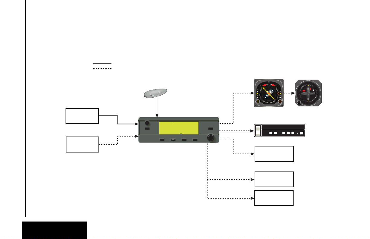
1. KLN 35A SYSTEM COMPONENTS
A basic KLN 35A system consists of a panel mounted KLN 35A GPS
and a KA 92 GPS antenna. An altitude input is required to obtain full
navigation and operational capabilities. Additional system components may be added or interfaced to the KLN 35A which increase its
features and capabilities. Some of these optional components
include an external course deviation indicator (CDI) or horizontal situation indicator (HSI), ARTEX ELS-10 emergency locator transmitter
(ELT), autopilot, and external annunciators.
The KLN 35A panel mounted unit contains the GPS sensor, the navigation computer, a liquid crystal display (LCD), and all controls
required to operate the unit.
A KA 92 GPS “patch” antenna is available for use with the KLN 35A.
It is designed to always be mounted on the top of the aircraft.
The KLN 35A has analog outputs to drive the left-right deviation bar
of most mechanical CDIs and HSIs. In addition, the NAV mode of
the Bendix/King KFC 150, KAP 150, KAP 150H, KAP 100, KFC 200,
KAP 200, KFC 250, KFC 275, KFC 300, and KFC 325 flight control
systems may be coupled to the KLN 35A. Many other autopilots may
also be coupled to the KLN 35A. Actual autopilot performance and
capability when coupled to the KLN 35A may vary significantly from
one autopilot model to another.
System Components
Chapter 1
Altitude may be provided to the KLN 35A from an encoding altimeter
or blind encoder. Altitude is used as an aid in position determination
when not enough satellites are in view.
Some installations may require remote annunciators to be mounted
in the aircraft panel in order to indicate the status of certain KLN 35A
functions, namely waypoint alert and message.
1-1
Effective Date 5/95006-08791-0000 Rev 0
Page 23
CANADA
USA
LATIN AM
PACIFIC
SOUTH PAC
SOUTH AM
EUROPE
EAST EUR
MID EAST
AFRICA
SOUTH PAC
PACIFIC
75°
60°
45°
30°
15°
0°
15°
30°
45°
60°
75°
60°
45°
30°
15°
0°
15°
30°
45°
60°
165°150°135°120°105° 90° 75° 60° 45° 30° 15° 0° 15° 30° 45° 60° 75° 90° 105°120°135°150°165°180°
Pacific Data Base
coverage area
Common to Pacific & Atlantic
Data Base coverage areas
Atlantic Data Base
coverage area
Americas Data Base
coverage area
Data Base
Chapter 2
Data Base
2-0
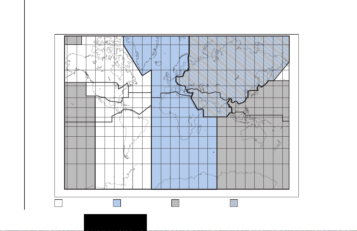
Figure 2-1 KLN 35A Data Base Geographical Region
Effective Date 5/95 006-08791-0000 Rev 0
Page 24

KLN 35A Pilot’s Guide Data Base
2.DATA BASE
2.1. DATA BASICS
The data base provides two primary functions. First, it makes pilot
interface with the GPS sensor much easier. Rather than having to
manually look up and then enter the latitude and longitude for a specific waypoint, it allows you to merely enter a simple waypoint
identifier. The data base automatically looks up and displays the latitude and longitude associated with the identifier. It should be obvious
that the data base saves a lot of tedious latitude/longitude entry and
also greatly reduces the potential for data input mistakes.
The second function of the data base is that it serves as a very convenient means to store and easily access aeronautical information.
Want to know the name of the airport, the nearest city, or the airport
altitude? Just unleash the power of the KLN 35A and display the
information right on the screen.
2.2. DATA BASE CONTENTS AND COVERAGE AREAS
There are three data base coverage areas available for the KLN 35A.
They are referred to as the “Americas” data base, the “Atlantic”data
base, and the “Pacific” data base.
Data Base
Chapter 2
The International Civil Aviation Organization (ICAO) and Aeronautical
Radio, Inc. (ARINC) break the world into the ten geographic regions
shown in figure 2-1. The KLN 35A Americas data base contains
aeronautical information for the group of ICAO regions consisting of
Canada, USA, Latin America, and South America. The KLN35A
Atlantic data base provides information for the ICAOregions of
Europe, Africa, East Europe, and Mid East. Likewise, the Pacific
data base provides information for East Europe, Mid East, Pacific and
South Pacific.
All three data bases contain complete information for all VORs and
NDBs in their respective coverage area. The data base also contains
public use and military airports which have any runway at least 1000
feet in length.
2-1
Effective Date 5/95006-08791-0000 Rev 0
Page 25

Data Base
The following is a listing of the KLN 35A data base contents:
AIRPORTS
Identifier
Name
City, State or Country
Use type (if military)
Latitude and Longitude
Elevation
Runway numbers, lengths, surfaces, and lighting
Communication frequencies
Chapter 2
Data Base
VORs
Identifier
Name
Frequency
Latitude and Longitude
Magnetic variation
NDBs
Identifier
Name
Frequency
Latitude and Longitude
(Note - Outer Compass Locators are not included in the data base)
250 USER DEFINED WAYPOINTS
Identifier
Latitude and Longitude
MISCELLANEOUS
Air Route Traffic Control Center (ARTCC and FIR) frequencies
Flight Service Stations (location of points of communication and
associated frequencies)
Special Use Airspace (SUA) boundaries (Prohibited, Restricted, Alert,
Class B, Class C, CTA, TMA, TRSA)
Effective Date 5/95 006-08791-0000 Rev 0
2-2
Page 26

KLN 35A Pilot’s Guide Data Base
2.3. ICAO IDENTIFIERS
Waypoints are stored in the KLN 35A data base almost exclusively
by their ICAO identifiers. ICAO (International Civil Aviation
Organization) is an internationally accepted reference for the data. In
almost all cases the proper ICAO identifiers may be taken directly
from Jeppesen Sanderson or government aeronautical charts.
Airport identifiers in the contiguous United States, Alaska, and
Canada are special cases in the ICAO system. Many airport identifiers for these areas have four letters beginning with a prefix letter
that corresponds to the geographic area in which it is located. The
prefix letter for the contiguous U.S. is “K”. Thus, the identifier for
Dallas/Fort Worth International Airport is KDFW, not DFW (which
would be identical to the VOR identifier). Likewise, the identifier for
Orlando Executive Airport is KORL while the VOR identifier is ORL.
The prefix letter for Canada is “C” and for Alaska is “P”.
NOTE: There are several exceptions in Alaska. In many cases, airports with three letter identifiers receive the prefix “P”, but there are
many that don’t. The most reliable method of determining an Alaska
airport identifier is to look it up from the airport name or city. See section 3.7.4, “Selecting Waypoints by Name or City”.
Incidentally, you can program the KLN 35A to default to a certain
letter (such as “K”) when you are entering a waypoint identifier. See
section 3.4.2, “Data Entry” to learn about this handy feature.
Data Base
Chapter 2
Not all airport identifiers receive the prefix letter. Airport identifiers
which are combinations of letters and numbers do not apply to the
prefix rule. Examples of airport identifiers not using the prefix are
3C2, 7TX6, and M33.
So remember, if you are entering or looking for an airport
identifier that is all letters (no numbers) then it will begin with a
“K” prefix in the contiguous U.S., a “P” in Alaska (in some
cases), or a “C” in Canada. If there are numbers in the identifier
then a prefix is not used. For other areas of the world the airport
identifier stored in the KLN 35A data base is identical to how it is
charted.
2-3
Effective Date 5/95006-08791-0000 Rev 0
Page 27

Data Base
2.4. UPDATING THE DATA BASE
The information stored in the data base would eventually become
obsolete if there wasn’t some means to update it. For example, new
airports open, navaids can move or change frequency,
communication frequencies can change, and on and on.
The data base is updated by means of a 3.5-inch diskette supplied by
AlliedSignal and an IBM-compatible personal computer. This method
does not have to involve removing the KLN 35A from the aircraft’s
instrument panel. A jack, usually mounted in the aircraft’s instrument
panel, provides a means of interfacing the KLN 35A with the computer via an interface cable. The diskettes are not returned to
AlliedSignal.
Chapter 2
Data Base
Every 28 days, AlliedSignal receives new NavData™information
from Jeppesen Sanderson. This information is processed and downloaded onto diskettes. AlliedSignal makes the update service
available to you in a choice of several subscription or random update
programs. See section 2.6 for details on these programs.
NOTE: AlliedSignal sends the update so that it arrives prior to the
next effective date. The new update may be installed any time prior
to the effective date and the KLN 35A will use the previous data up to
the effective date and automatically begin using the new data on the
effective date.
In order to use the update program you must have access to a computer having a disk drive capable of utilizing 3.5-inch 1.44 megabyte
high density diskettes. This computer also needs to have an available COM1 or COM2 serial port. If you wish to perform updates in
the cockpit, an optional PC Interface kit must be used. Included in
the kit is an interface cable that plugs into both the computer and into
the data loader jack. The data loader jack is included with the KLN
35A installation kit and is typically installed in the aircraft’s instrument
panel.
CAUTION: The data base must be updated only while the aircraft is on the ground. The KLN 35A does not perform any
navigation function while the data base is being updated. Since
a data base update takes approximately 10 minutes it is a good
idea to turn off all electrical equipment on the aircraft except for
the KLN 35A to avoid running down the aircraft battery.
Effective Date 5/95 006-08791-0000 Rev 0
2-4
Page 28

KLN 35A Pilot’s Guide Data Base
ее.еnm Update data
ееееее base on
>Leg ground only:
SET 3 Update pub DB?
APT VOR NDB SUP ACT NAV FPL CAL SET OTH
ее.еnm Update data
ееееее base on
#>Leg ground only:
CRSR
Update pub DB?
APT VOR NDB SUP ACT NAV FPL CAL SET OTH
NOTE: The diskettes sent to you can only be used to update one
KLN 35A, although they can update that specific unit numerous
times. The first time the diskettes are used in an update operation, a
unique identification code from the KLN 35A being used is uploaded
to the diskettes. These diskettes may be used in this specific KLN
35A an unlimited number of times which could be required if you
switch back and forth between the Americas, Atlantic, and Pacific
data bases during one update cycle. These diskettes may not, however, be used to update other KLN 35As. This update protection
ensures that Jeppesen Sanderson is properly compensated for the
use of their NavData™.
To update the KLN 35A data base:
1. Plug the 9 pin female connector end of the interface cable into a
COM serial port of the computer. If the computer has COM 1
and COM 2 serial ports, either may be used. Some computers
use a 9 pin COM serial port connector while other computers use
a 25 pin connector. If the computer being used has a 9 pin connector, the interface cable connector will plug directly into the
computer’s 9 pin connector. If the computer’s COM serial port
uses a 25 pin connector, use the 25 pin to 9 pin adapter included
in the PC interface kit to adapt the interface cable’s connector to
the computer’s connector.
Data Base
Chapter 2
2. If you are using the PC interface kit in the cockpit, plug the other
end of the interface cable (4 conductor male connector) into the
data loader jack that is mounted in the aircraft panel.
3. Insert the diskette into the computer’s disk drive. Turn on the
computer being used for the data base update. The program on
the disk will automatically “boot” (load) and the computer screen
will display “Ready” when the computer is ready to continue with
the data base update operation.
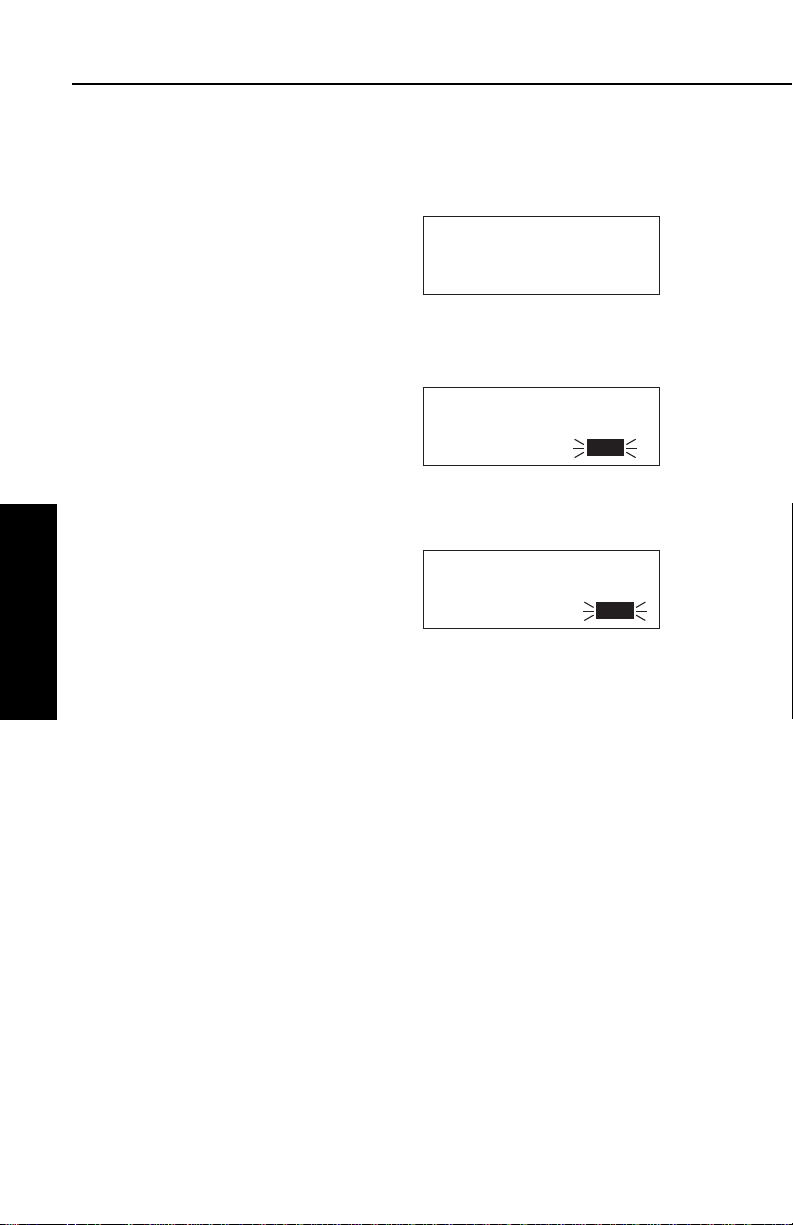
4. Turn on the KLN 35A. Press F
as required to approve the Self
Test, Initialization, VFR, and Data
Base pages. Use the right outer
knob to select the Setup (SET)
type pages and the right inner
knob to select the SET 3 page
(figure 2-2).
5. Press B. Update Pub DB? will
now be inverse video as in
figure 2-3.
2-5
Figure 2-2
Figure 2-3
Effective Date 5/95006-08791-0000 Rev 0
Page 29
Data Base
6.Press F. The estimated load
time in minutes is now displayed
(figure 2-4).
NOTE: In step 6, repeatedly pressing
E
will terminate the update process
ее.еnm Estimated load
ееееее time: 5 min
#>Leg
CRSR Approve?
APT VOR NDB SUP ACT NAV FPL CAL SET OTH
Figure 2-4
and bring the display back to the original SET 3 page shown in figure 2-2.
7.Press Fto acknowledge the estimated load time and begin
erasing the existing data base. The unit will now display Erasing
data base. After the data base
has been erased, the loading of
the new data automatically
Chapter 2
Data Base
begins. As the new data is being
loaded, the percentage of transfer
is displayed (figure 2-5).
8.The KLN 35A will indicate when
the data base update is complete
as shown in figure 2-6. You may
either turn the KLN 35A off at this
point or press Fto restart the
KLN 35A.
ее.еnm Programming
ееееее data base
>Leg 95% complete
CRSR
APT VOR NDB SUP ACT NAV FPL CAL SET OTH
Figure 2-5
ее.еnm Published data
ееееее base update
#>Leg complete
CRSR Acknowledge?
APT VOR NDB SUP ACT NAV FPL CAL SET OTH
Figure 2-6
9.Remove the interface cable. Remove the disk from the computer. Turn off the computer.
The chances are small of having difficulty updating the data base
but—
If you have a problem:
• First check that the interface cable is properly connected and that
the computer is turned on. If there is a problem with the
connection or the computer the KLN 35A will display Data
Loader Not Ready. When the problem is corrected this prompt
is removed and the update operation can continue from where it
left off.
• If an internal test fails after the data has been loaded, the KLN
35A will display Checksum Error, Data Base Invalid. Press
F to acknowledge. The KLN 35A will then display Data Base
Update Failed, Retry?Use the right outer knob to position the
cursor over the desired choice and press F.
Effective Date 5/95 006-08791-0000 Rev 0
2-6
Page 30

KLN 35A Pilot’s Guide Data Base
• There are other error messages that may be displayed. If you
have a problem that you can’t resolve, write down any error
messages to aid your AlliedSignal Service Center in identifying
the problem.
2.5. USER DEFINED DATA BASE
In addition to the published data base of airports, VORs, and NDBs
stored in the Jeppesen data base, you may create up to 250 other
user-defined waypoints. Section 4.4, “Creating User-defined
waypoints” describes this further.
The KLN 35A contains an internal lithium battery that is used to
“keep-alive” the user-defined data base as well as flight plans. This
battery has a typical life of three to five years.
recommended that the battery be replaced every three years at an
authorized AlliedSignal Service Center.
2.6. DATA BASE UPDATE SERVICE OPTIONS
The following tear-out page can be used for ordering the Americas,
Atlantic, and Pacific data base update services from AlliedSignal.
The forms may be mailed or FAXed for your convenience.
It is highly
Data Base
Chapter 2
2-7
Effective Date 5/95006-08791-0000 Rev 0
Page 31

Data Base
Chapter 2
Data Base
This page intentionally left blank
Effective Date 5/95 006-08791-0000 Rev 0
2-8
Page 32

KLX 35A Data Base Update Service Order Form
Consult Pricing Sheet (006-08794-0001) for Service Prices
AlliedSignal CAS offers several update
service options to suit your requirements.
Please select the service desired, then
fill out and mail this order form. Credit
card orders may be faxed.
Note: Updates are current for 28 days
after effective date on diskette. If you
select any service other than the complete 13-time service, your KLX 35A will
begin alerting you after 28 days that
your data base is out of date.
Diskette Format Only
(Laptop Computer Required. See
section 2 of KLX 35A Pilot’s Guide
for details.)
Check Requested Data Base:
Americas Data Base
Atlantic International Data Base
Pacific International Data Base
Check One:
Complete Update Service.
Provides 13 updates–one every 28
days for one year.
Six-time Update Service. Provides
six updates–one every 56 days for
one year.
Four-time Update Service.
Provides four updates–one during
each quarter for one year.
Single Update. Provides one
update upon receipt of order.
Please set up the service under:
Name:
Company:
Address:
City:
State: Zip Code:
Country:
Telephone: ( )
FAX: ( )
Aircraft Make:
Aircraft Model:
Method of Payment
Check/Money order enclosed
Wire Transfer:
Chase Manhattan Bank, NY
Acct #910-2-538734
MasterCard/VISA
Number
Expires
Signature
Tax may apply in some states.
See pricing sheet.
A
Send to:
AlliedSignal CAS
Data Base Update Service
Mail Drop #66
400 N. Rogers Road
Olathe KS 66062-1212
Telephone: (913) 768-3020
FAX: (913) 768-3904
Page 33

Fold here
Tape here
NO POSTAGE
NECESSARY
IF MAILED
UNITED STATES
BUSINESS REPLY MAIL
FIRST-CLASS MAIL PERMIT NO. 121 OLATHE, KANSAS
POSTAGE WILL BE PAID BY ADDRESSEE
ALLIEDSIGNAL COMMERCIAL AVIONICS SYSTEMS
M D 66
400 NORTH ROGERS ROAD
OLATHE KS 66062-9987
IN THE
Page 34

89.6nm ∂∆ KOSH
105kt > ««««∑∏π««««
>Leg DTK343° TK344°
NAV 1 >345°To 0:51
APT VOR NDB SUP ACT NAV FPL CAL SET OTH
GPS
KLN 35A
B
CRSR
MSG D CLR ENT
Pull
SCAN
Push
ON
∫
DIRECT-TO
BUTTON
MESSAGE
BUTTON
CLEAR
BUTTON
ENTER
BUTTON
RIGHT INNER
KNOB
RIGHT OUTER
KNOB
CURSOR
BUTTON
NEAREST
BUTTON
ON/OFF
SWITCH
NRST
Figure 3-1 KLN 35A Controls
Page 35

Basic GPS Operation
Chapter 3
Basic GPS Operation
Effective Date 5/95 006-08791-0000 Rev 0
3-0
Page 36

KLN 35A Pilot’s Guide Basic GPS Operation
3.BASIC GPS OPERATION
3.1. COVERAGE AREA
The KLN 35A was designed to provide worldwide navigation coverage from North 74°latitude to South 60°Latitude (figure 3-2).
Outside this area, magnetic variation must be manually entered as
discussed in section 4.6, “Operation Outside the Primary Coverage
Area”. See section 2.2 for the data base geographical regions.
Basic GPS Operation
Chapter 3
Figure 3-2 KLN 35A Navigation Coverage Area
3.2. TURN-ON AND SELF TEST
Well, it’s time to get down to business and actually use the KLN 35A!
Figure 3-1 can be folded out and used as a reference during the
following procedures. This is especially handy if you’re learning while
away from your GPS. The steps below take a lot of words to explain,
but before you know it, you will be “flying” through them.
NOTE: When power is applied to the KLN 35A it always “wakes up”
in the En route-Leg mode. Only the En route-Leg mode is described
in this chapter. In this mode the KLN 35A performs great circle
navigation (the shortest distance between two points located on the
earth’s surface). The course deviation output displayed on the unit’s
internal course deviation indicator (CDI) and provided to an external
horizontal situation indicator (HSI) or CDI is five nautical miles (full
scale sensitivity) left and right. The other mode is En route-OBS and
is described in section 4.5.3.
3-1
Effective Date 5/95006-08791-0000 Rev 0
Page 37
Basic GPS Operation
To turn on and initialize the KLN 35A:
1.Turn on the KLN 35A by pushing in the power switch.
The Turn-On page (figure 3-3) will
be displayed for a few seconds.
During this time, the KLN 35A
performs an extensive internal
test. The operational revision
status (ORS) level number in the
upper right corner of the display
should match the ORS level
indicated on the cover of this
Pilot’s Guide .
When the internal test is complete, the Turn-On page will
automatically be replaced by the
Self Test page (figure 3-4).
NOTE: If the KLN 35A is operating in
the Take-Home Mode, the TakeHome Warning Page (figure 3-5) is
displayed first and must be
acknowledged by pressing F. See
Chapter 3
section 4.7 for more information on
the Take-Home mode.
Basic GPS Operation
KLN 35A GPS ORS 01
Self-Test in Progress
©1995 AlliedSignal
Avionics, Inc.
APT VOR NDB SUP ACT NAV FPL CAL SET OTH
««««“‘”««««
Baro: 29.92"
Altitude 1138ft
ANNUN ON Pass Ok?
APT VOR NDB SUP ACT NAV FPL CAL SET OTH
WARNING
System in Take-home
Mode: DO NOT USE FOR
NAVIGATION Ok?
APT VOR NDB SUP ACT NAV FPL CAL SET OTH
Figure 3-3
∫
Figure 3-4
Figure 3-5
2.Verify that the data displayed on the Self Test page is the same
as is being displayed on the appropriate indicator (if any) in the
aircraft which is interfaced to the KLN 35A. If the KLN 35A is not
connected to any other equipment in the aircraft, you may skip to
step 3.
If the KLN 35A is interfaced with a NAV indicator such as an HSI
or a course deviation indicator (CDI), the deviation bar (D-bar)
should be indicating a half scale deviation to the right. The
TO/FROM indicator should be showing FROM.
If any of the above checks fail, do not use the associated
indicator with the KLN 35A.
3.If the KLN 35A has passed the internal self test, the bottom of the
Self Test page will display Passand all external annunciators
should be illuminated. If instead, Failis displayed, recycle power
to the KLN 35A. If the Self Test page still displays Fail, the
KLN 35A requires repair and should not be used for navigation.
Effective Date 5/95 006-08791-0000 Rev 0
3-2
Page 38

KLN 35A Pilot’s Guide Basic GPS Operation
APT VOR NDB SUP ACT NAV FPL CAL SET OTH
20 DEC 95 1415 UTC
WPT: Ref KIXD
N 38°49.91' 330°Fr
W 94°53.38' Ok? 0.8nm
APT VOR NDB SUP ACT NAV FPL CAL SET OTH
20 DEC 95 1415 UTC
WPT: Ref KIXD
N 38°49.91' 330°Fr
W 94°53.38' Ok? 0.8nm
APT VOR NDB SUP ACT NAV FPL CAL SET OTH
07 --- -- 1415 UTC
WPT: Ref KIXD
N 38°49.91' 330°Fr
W 94°53.38' Ok? 0.8nm
APT VOR NDB SUP ACT NAV FPL CAL SET OTH
07 JAN 96 1415 UTC
WPT: Ref KIXD
N 38°49.91' 330°Fr
W 94°53.38' Ok? 0.8nm
4. When you are ready to approve the Self-test page, press the F
button while the Ok? is flashing. If it happens not to be flashing,
press the B button and use the right outer knob to move the
cursor there.
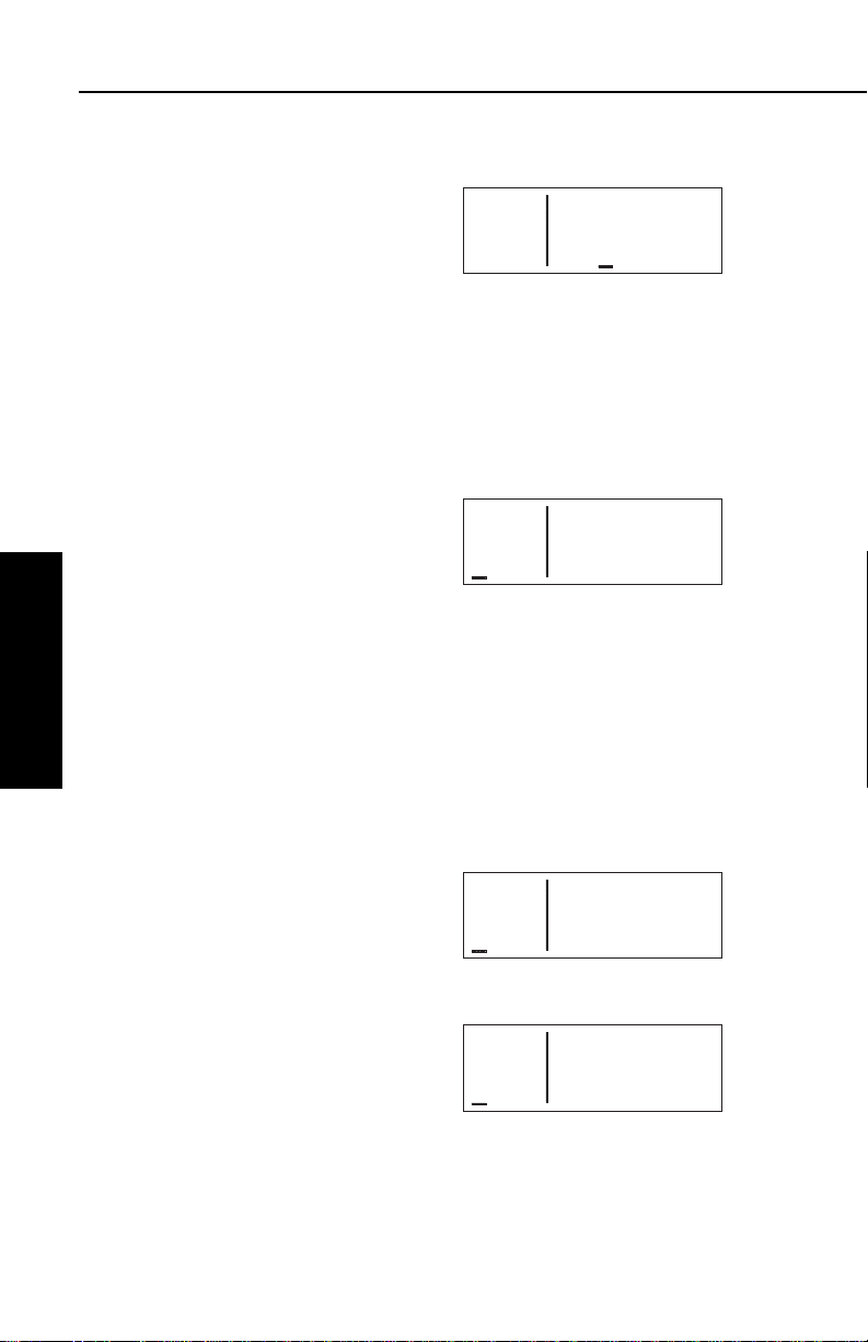
5. The next page displayed will be
the Initialization page (figure 3-6).
Verify that the date displayed in
the top left corner of the
Initialization page is correct. The
KLN 35A has an internal battery
powered calendar/clock, so the
date and time normally don’t require setting. The battery has a
life of approximately 3 years. In addition, the KLN 35A’s system
date and time are automatically updated very precisely when at
least one satellite is being received. However, if for some reason
the date or time are incorrect, it is necessary to enter the correct
date or time so that the KLN 35A can reach the navigation mode.
The date must be correct and the time must be correct within ten
minutes so that the KLN 35A will start looking for the correct
satellites.
If the date is incorrect, rotate the
right outer knob counterclockwise
until the cursor is over the entire
date field (figure 3-7). Rotate the
right inner knob until the correct
day of the month is displayed
(figure 3-8). Then, move the cursor to the month field by rotating
the outer knob one click
clockwise and change the month
as necessary. Use the same
methods to select the correct
year (figure 3-9). When the date
is correct, press F.
Figure 3-6
Figure 3-7
Figure 3-8
Basic GPS Operation
Chapter 3
6. Verify that the time displayed in
the upper right corner of the
Initialization page is correct to
within ten minutes of the actual
time. Remember, once the KLN 35A receives the first satellite, it
will automatically be very accurately updated by the satellite to
the correct time. However, you are responsible for assuring the
3-3
Figure 3-9
Effective Date 5/95006-08791-0000 Rev 0
Page 39

Basic GPS Operation
APT VOR NDB SUP ACT NAV FPL CAL SET OTH
07 JAN 96 1415 UTC
WPT: Ref KIXD
N 38°49.91' 330°Fr
W 94°53.38' Ok? 0.8nm
APT VOR NDB SUP ACT NAV FPL CAL SET OTH
07 JAN 96 0615 EST
WPT: Ref KIXD
N 38°49.91' 330°Fr
W 94°53.38' Ok? 0.8nm
desired time zone is selected on
the KLN 35A. If it is necessary to
reset the time, position the cursor
over the time zone field
(figure 3-10) and select the
desired time zone (figure 3-11).
The following are the time zones which the KLN 35A is capable
of displaying:
UTC Coordinated Universal Time (Zulu)
GST Greenland Standard Time (UTC - 3)
GDT Greenland Daylight Time (UTC - 2)
ATS Atlantic Standard Time (UTC - 4)
ATD Atlantic Daylight Time (UTC - 3)
EST Eastern Standard Time (UTC - 5)
Chapter 3
Basic GPS Operation
EDT Eastern Daylight Time (UTC - 4)
CST Central Standard Time (UTC - 6)
CDT Central Daylight Time (UTC - 5)
MST Mountain Standard Time (UTC - 7)
MDT Mountain Daylight Time (UTC - 6)
PST Pacific Standard Time (UTC - 8)
PDT Pacific Daylight Time (UTC - 7)
AKS Alaska Standard Time (UTC - 9)
AKD Alaska Daylight Time (UTC - 8)
HAS Hawaii Standard Time (UTC - 10)
HAD Hawaii Daylight Time (UTC - 9)
SST Samoa Standard Time (UTC - 11)
SDT Samoa Daylight Time (UTC - 10)
LCL Local Time Zone (user-defined)
Figure 3-10
Figure 3-11
You will be able to change the time zone any time you desire on
several other pages, so don’t worry if you’re not sure which time
zone to choose. UTC—Coordinated Universal Time (also called
“Zulu”) is always a safe choice.
Effective Date 5/95 006-08791-0000 Rev 0
3-4
Page 40

KLN 35A Pilot’s Guide Basic GPS Operation
APT VOR NDB SUP ACT NAV FPL CAL SET OTH
07 JAN 96 14-- EST
WPT: Ref KIXD
N 38°49.91' 330°Fr
W 94°53.38' Ok? 0.8nm
APT VOR NDB SUP ACT NAV FPL CAL SET OTH
07 JAN 96 1430 EST
WPT: Ref KIXD
N 38°49.91' 330°Fr
W 94°53.38' Ok? 0.8nm
APT VOR NDB SUP ACT NAV FPL CAL SET OTH
07 JAN 96 1430 EST
WPT: K Ref KIXD
N 38°49.91' 330°Fr
W 94°53.38' Ok? 0.8nm
APT VOR NDB SUP ACT NAV FPL CAL SET OTH
07 JAN 96 1430 EST
WPT: KJFK Ref KIXD
N 38°49.91' 330°Fr
W 94°53.38' Ok? 0.8nm
The local time zone (LCL) is selected on the SET 2 page, and is
defined to be a certain time offset from Zulu (UTC).
Once you have selected the desired time zone, position the cursor over the entire time field and select the correct hour with the
right inner knob (figure 3-12).
Since 24 hour time is used, be
sure to add 12 if the time is after
1:00 P.M. (2:30 P.M. becomes
1430). Now move the cursor to
the tens of minutes position and
select the desired value, and
repeat this process for the last
digit of the time field. When the
correct time has been entered
(figure 3-13), press F to start
the clock running. Don’t worry
that you can’t update the
seconds. The KLN 35A system
time will automatically be corrected very precisely once a satellite is received.
7. To aid the GPS receiver in acquiring your position, it is vital that it
have a reasonable idea of where you are, and the Initialization
page is where you have the chance to set this initial position.
Check to see if the displayed initial position is where you actually
are. This latitude/longitude is the last known position before the
power was shut down the last time. Unless the unit has been
moved since its last use, this position should be correct. On the
right side of the screen will be the identifier of the nearest airport
in the data base, with a radial and distance from that airport. If
you need to change the initial position to—let’s say—John F.
Kennedy International (KJFK), move the cursor to the WPT: field
and use the right inner knob to
select a K as the first character of
the identifier (figure 3-14). Move
the cursor to the right one character and select a J and then
right again to select an F. The
final K should be filled in by the
data base (figure 3-15). When
you press F, the latitude and
longitude fields will change to
Figure 3-12
Figure 3-13
Figure 3-14
Basic GPS Operation
Chapter 3
3-5
Figure 3-15
Effective Date 5/95006-08791-0000 Rev 0
Page 41

Basic GPS Operation
APT VOR NDB SUP ACT NAV FPL CAL SET OTH
AMERICAS
Data Base Expires
12 OCT 1996
Acknowledge?
APT VOR NDB SUP ACT NAV FPL CAL SET OTH
ATLANTIC INTL
Data Base Expired
12 OCT 1996
Acknowledge?
APT VOR NDB SUP ACT NAV FPL CAL SET OTH
ее.еnm KORL
ееееее ATIS* 127.25
>Leg CLR * 128.45
APT+4 GRND* 121.40
APT VOR NDB SUP ACT NAV FPL CAL SET OTH
07 JAN 96 1430 EST
WPT: KJFK Ref KJFK
N 40°38.41' ---°Fr
W 73°46.67' Ok? 0.0nm
those of KJFK (figure 3-16). If
necessary, the latitude and longitude may be entered manually.
8. When all information on the
Initialization page is correct, move
the cursor to Ok? and press F
to move on.
9. The VFR page will be displayed to notify you that the GPS is for
VFR use only.
10. The Data Base page will now be displayed with the cursor over
Acknowledge?. Line 1 indicates whether an Americas, Atlantic,
or Pacific data base is being used. If the data base is current, line
3 will show the date when the
data base expires (figure 3-17).
If, on the other hand, the data
base is out of date, line 3 shows
the date that it expired
(figure 3-18). The KLN 35A will
still function with an out of date
data base; however, you must
exercise extreme caution and
Chapter 3
Basic GPS Operation
always verify that the data base
information is correct before using
information from an out-of-date
data base. Press F to acknowledge the information on the Data Base page.
Figure 3-16
Figure 3-17
Figure 3-18
WARNING: The accuracy of the data base information is
assured only if the data base is current. Operators using an outof-date data base do so entirely at their own risk.
A waypoint page for the waypoint which was active when the KLN
35A was last turned off will be displayed on the screen. If the last
active waypoint was an airport, the APT 4 page showing the airport’s
communications frequencies will be
displayed (figure 3-19). We thought
you’d like that! Almost always, the
waypoint which was active when you
last turned the KLN 35A off is the airport where you landed. Therefore,
when you get ready to depart, the air-
Figure 3-19
port communication frequencies for that airport will automatically be
displayed for you!
Effective Date 5/95 006-08791-0000 Rev 0
3-6
Page 42

KLN 35A Pilot’s Guide Basic GPS Operation
Next, you’ll probably want to check the NAV 2 page to see your present position. Use the right outer knob to select the NAV page type
and then the right inner knob, if necessary, to select the NAV 2 page. It
is quite likely that the present position
will be dashed at first (figure 3-20). It
takes the KLN 35A several minutes to
acquire the GPS satellites and to
make its initial calculation of your
position. When the KLN 35A reaches
a NAV ready status and is able to
navigate, the NAV 2 page will display
your present position relative to the
nearest VOR (figure 3-21). Verify
that the present position shown on
the NAV 2 page is correct.
NOTE: In order to reach a Nav ready status, the aircraft must be
away from obstructions blocking the GPS antenna’s view of required
satellites. If the KLN 35A fails to reach a Nav ready status within five
minutes refer to section 3.6, “Initialization And Time To First Fix”.
3.3. DISPLAY FORMAT
--.-nm >Present Posn
----- >Leg Ref: ----NAV 2 ---°Fr ----nm
APT VOR NDB SUP ACT NAV FPL CAL SET OTH
Figure 3-20
0.9nm >Present Posn
KORL
>Leg Ref: ORL
NAV 2 030°Fr 0.4nm
APT VOR NDB SUP ACT NAV FPL CAL SET OTH
Figure 3-21
Basic GPS Operation
Chapter 3
The KLN 35A uses a Liquid Crystal Display (LCD). In normal operation, the display screen is divided into two segments by a vertical line,
called the page divider. In some cases, such as the display of
system messages or the turn-on and self test sequence, the page
divider disappears and you have a “full-screen” page.
Aeronautical information (or
data
) is presented on the screen in the
form of “pages”. A page is a presentation of specific data in an
organized format. Various page “types” are used to display related
kinds of data. For example, one page type is NAV (navigation). NAV
pages show information such as distance, groundspeed, bearing,
course, and other data relating to navigation. Another page type is
APT (airport). APT pages contain information pertinent to a specific
airport such as name, city, State, elevation, and direction and distance relative to the aircraft’s present position.
The top left corner of the screen
always displays distance to the active
waypoint (figure 3-22). The identifier
of the active waypoint is usually displayed on the second line. This area
3-7
7.6nm DATE/TIME
KIXD 12 DEC 95
>Leg 1941:18 CST
SET 2 Central Std
APT VOR NDB SUP ACT NAV FPL CAL SET OTH
Figure 3-22
Effective Date 5/95006-08791-0000 Rev 0
Page 43
Basic GPS Operation
APT VOR NDB SUP ACT NAV FPL CAL SET OTH
ее.еnm KICT
ееееее ATIS 125.15
>Leg CLR 125.70
APT+4 GND 121.90
APT VOR NDB SUP ACT NAV FPL CAL SET OTH
ее.еnm KICT
ееееее TWR 118.20
>Leg UNIC 122.95
APT+4 CL C 126.70
APT VOR NDB SUP ACT NAV FPL CAL SET OTH
ее.еnm KISM
ееееее KISSIMMEE MUN
>Leg ORLANDO
APT 1 FL
APT VOR NDB SUP ACT NAV FPL CAL SET OTH
22.5nm ∂∆ KTOP
110kt > ««««∑∏π««««
>Leg DTK121° TK126°
NAV 1 >121°To 0:12
∫
of the display is very useful, since it lets you know where you’re going
and how far until you get there.
NOTE: In cases when the active
waypoint identifier is displayed on the
right side of the page divider, line 2
will display the current groundspeed
(figure 3-23)
NOTE: For purposes of this Pilot’s Guide, many of the screen illustrations do not show actual navigation data in this area as in figure
3-24. In these cases, the displayed data is not relevant to the discussion of the KLN 35A operation.
In normal operation, the aeronautical
data is displayed on the right side of
the screen. The bottom line on the
left side of the page divider indicates
the page type that is being displayed
on the right side of the page divider.
In figure 3-24, the APT 1 (airport 1)
page is being displayed.
You might think of the page types as the chapters in a book and the
Chapter 3
page numbers as the pages within a chapter. Just as a chapter in a
book may have from one to many pages, a KLN 35A page type may
Basic GPS Operation
have from two to 10 pages associated with it. There are, for
example, 10 flight plan pages (FPL 0, FPL 1, FPL 2, ..., FPL 9) in the
flight plan page type and five airport pages (APT 1, APT 2, APT 3,
APT 4, APT 5) in the airport page type.
Figure 3-23
Figure 3-24
Figure 3-25 shows an example of an
APT 4 page. Notice the “+” sign in
the page identification. Whenever a
“+” sign is part of a page identifier
there will be two or more pages, all
having the same page number, used
Figure 3-25
to present all of the required information. That is, all of the information
associated with a particular page
number doesn’t fit on the page being
viewed. In this case the “+” sign indicates that there are two or more APT
4 pages. Figure 3-26 shows the sec-
Figure 3-26
ond APT 4 page for KICT (Wichita Mid-Continent Airport).
Effective Date 5/95 006-08791-0000 Rev 0
3-8
Page 44

KLN 35A Pilot’s Guide Basic GPS Operation
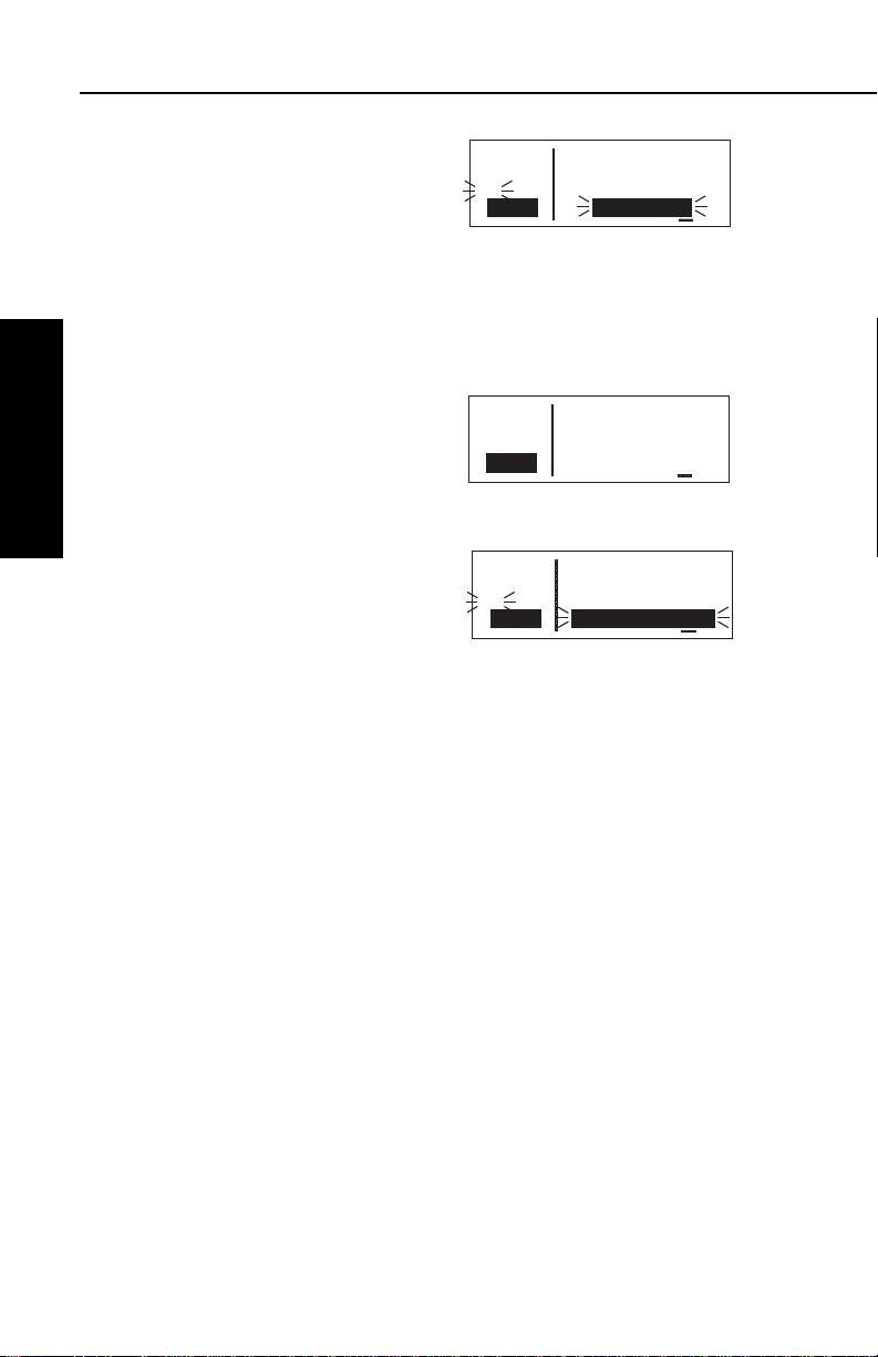
The third line of the left side has three purposes: (1) If the KLN 35A
is ready for you to approve something, such as a selected waypoint,
the “Ent” prompt will flash (figure 3-27), indicating you should press
the Fbutton to continue. (2) If the
KLN 35A has a new message for you
which must be viewed on a message
page, a large “M” will flash in the
same area (figure 3-28) telling you to
press the Cbutton and view the
new message. (3) Immediately to the
right of the “message/enter” display
area, the navigation mode (see sec-
tion 4.5 for details) is displayed. If the
KLN 35A is in the En route-Leg mode
(the normal mode of operation), “Leg”
will be displayed here.
The lower left corner of the display, where the page type and number
are usually displayed, can also display short operational messages to
the user called “scratchpad messages”. These messages are
displayed for approximately five
seconds, then this area returns to the
page type and number. Figure 3-29
shows an example of a scratchpad
message indicating a duplicate
identifier. A complete listing of
scratchpad messages is available in
Appendix C of this Pilot’s Guide.
åå.ånm ZBV 116.70
ееееее BIMINI
#>Leg N 25°42.10'
VOR 1 W 79°17.10'
APT VOR NDB SUP ACT NAV FPL CAL SET OTH
Figure 3-27
åå.ånm ZBV ∂∆ KSEA
ееееее > ««««∑∏∫««««
{>Leg 62.1nm 112kt
NAV 1 >262°To 0:33
APT VOR NDB SUP ACT NAV FPL CAL SET OTH
Figure 3-28
åå.ånm H 276
ееееее HOTEL
Dup N 55°49.90'
Ident W 55°45.70'
APT VOR NDB SUP ACT NAV FPL CAL SET OTH
Figure 3-29
Basic GPS Operation
Chapter 3
3-9
Effective Date 5/95006-08791-0000 Rev 0
Page 45

Basic GPS Operation
APT VOR NDB SUP ACT NAV FPL CAL SET OTH
ее.еnm KICT
ееееее ATIS 125.15
#>Leg CLR 125.70
CRSR GND 121.90
APT VOR NDB SUP ACT NAV FPL CAL SET OTH
åå.ånm >Present Posn
ееееее
>Leg N 39°43.20'
CRSR W 86°17.21'
3.4. BASIC OPERATION OF PANEL CONTROLS
The KLN 35A controls are very easy to use. Most of the page selection and data entry is done with the knobs on the right side of the
front panel and the cursor (B) button immediately above them. The
G button is located on the left side , and there are four buttons
across the bottom: C (Message), D (Direct To), E (Clear), and
F (Enter). The operation of these buttons will be described on the
next few pages.
The cursor is an area of inverse video (light characters on a dark
background) on the screen. Many pages allow you to add, delete, or
change data on the screen by first pressing the B button to turn the
cursor function on and bring the cursor on the screen. The right
knobs are then used to enter or
change data. When the cursor is on
the screen, the lower left corner of the
screen will show CRSR in inverse
video rather than the page name for
that particular page (figure 3-30). The
cursor is over Present Posn.
There are times when the cursor is
flashing. Figure 3-31 shows an
example of how “whiskers” are used
Chapter 3
in this Pilot’s Guide to depict a flash-
Basic GPS Operation
ing cursor (over ATIS 125.15). In
addition, it shows an example of how
“whiskers” around normal text is used to depict normal (non-inverse)
characters flashing. The letters Ent are flashing but are not in
inverse video.
Figure 3-30
Figure 3-31
3.4.1. PAGE SELECTION It is now time to learn to select a desired page.
NOTE: The cursor function is not used in selecting pages and the
B
button should not be pressed at this time. If CRSR is annunciated in the lower left corner of the display, press the Bbutton to turn
the cursor function off.
Effective Date 3/96 006-08791-0000 Rev 1
3-10
Page 46

KLN 35A Pilot’s Guide Basic GPS Operation
Chapter Name/
Page # Range Page Type Page Functions
APT 1-5 Airport Directory of published
airports
VOR 1-2 VOR Directory of published
VOR stations
NDB 1-2 NDB Directory of published
non-directional beacons
(NDB)
SUP 0-3 Supplemental Wpt Directory of user-defined
waypoints
ACT * Active Waypoint Information about the
active waypoint
NAV 1-4 Navigation Navigation data
FPL 0-9 Flight Plan Active and stored flight
plans
CAL 1-6 Calculator Distance, bearing, time
and fuel calculator; air
data calculations based
on pilot-entered data
SET 1-8 Setup Setting initial position and
date/time, updating the
data base, and selecting
certain features
OTH 1-5 Other Status reports, and
deleting user wpts and
remarks
*Varies with the type of waypoints in the active flight plan.
The right outer knob is rotated to select one of ten page types for the
display. These ten page types are the following:
Remember that the page type is displayed at the lower left corner of
the screen. The first three letters of the page type are always used
for annunciation on the screen, for example, CAL represents
Calculator page. The page type is also annunciated by means of a
bar on the display, which moves as you turn the right outer knob. All
the page types are listed across the front panel directly under the dis-
Basic GPS Operation
Chapter 3
3-11
Effective Date 5/95006-08791-0000 Rev 0
Page 47

Basic GPS Operation
play, and the bar will always be over one of them. For example, let’s
say you were on an APT page
(figure 3-32) and you wanted to turn
to a SET page. You would look at the
list and see that the SET pages are
eight places to the right of the APT
pages. Therefore, turning the right
outer knob eight clicks clockwise will
get you to the SET pages
(figure 3-33). The annunciator bar
and the page labels work kind of like
a map to get you from one page type
to another. The page type selection
wraps around from Other (OTH) to
Airport (APT); that is, the knob has no mechanical stops.
Once you have selected the desired page type using the right outer
knob, you may select the page number by rotating the right inner
knob. Let’s use an example to make sure you understand. You are
presently viewing the APT 2 page and you wish to view the NAV 3
page. Rotating the right outer knob 5 (five) clicks clockwise will
display the NAV page that you last viewed—we’ll say the NAV 2
page. Turning the right inner knob one click clockwise or three clicks
counterclockwise will bring you to the NAV 3 page. Got it?
Chapter 3
NOTE: In this Pilot’s Guide the right smaller knob is assumed to be
Basic GPS Operation
in the “in” position unless it specifically states that he knob should be
in the “out” position. Therefore, the words “rotate the right inner
knob” mean to turn the right inner knob while the knob is in the “in”
position.
ее.еnm KISM
ееееее KISSIMMEE MUN
>Leg ORLANDO
APT 1 FL
APT VOR NDB SUP ACT NAV FPL CAL SET OTH
Figure 3-32
ее.еnm TURN
ееееее ANTICIPATION
>Leg ENABLED
SET 4
APT VOR NDB SUP ACT NAV FPL CAL SET OTH
Figure 3-33
3.4.2. DATA ENTRY
Now that you’ve learned how to select the desired page, you’re ready
to learn the means of entering data. It is necessary to enter data, for
example, in order to specify a waypoint of your choice to go Direct
To. The general procedure for entering a waypoint identifier is
described below and is shown in figures 3-34 through 3-42 for entering a waypoint (in this case, First Flight airport in North Carolina,
identifier KFFA) on the Calculator (CAL) 1 page.
Effective Date 3/96 006-08791-0000 Rev 1
3-12
Page 48

KLN 35A Pilot’s Guide Basic GPS Operation
APT VOR NDB SUP ACT NAV FPL CAL SET OTH
åå.ånm >Wpt Fr>KRDU
ееееее To>KSAV
>Leg 255nm Brg 209°
CRSR 121kt ETE 2:06
APT VOR NDB SUP ACT NAV FPL CAL SET OTH
åå.ånm >Wpt Fr>K
ееееее To>KSAV
>Leg 255nm Brg 209°
CRSR 121kt ETE 2:06
APT VOR NDB SUP ACT NAV FPL CAL SET OTH
åå.ånm >Wpt Fr>K
ееееее To>KSAV
>Leg 255nm Brg 209°
CRSR 121kt ETE 2:06
APT VOR NDB SUP ACT NAV FPL CAL SET OTH
åå.ånm >Wpt Fr>KF2
ееееее To>KSAV
>Leg 255nm Brg 209°
CRSR 121kt ETE 2:06
APT VOR NDB SUP ACT NAV FPL CAL SET OTH
åå.ånm >Wpt Fr>KFFA
ееееее To>KSAV
#>Leg 255nm Brg 209°
CRSR 121kt ETE 2:06
APT VOR NDB SUP ACT NAV FPL CAL SET OTH
åå.ånm >Wpt Fr>KRDU
ееееее To>KSAV
>Leg 255nm Brg 209°
CRSR 121kt ETE 2:06
APT VOR NDB SUP ACT NAV FPL CAL SET OTH
ее.еnm >Wpt Fr>KRDU
ееееее To>KSAV
>Leg 255nm Brg 209°
CAL 1 121kt ETE 2:06
To enter a waypoint identifier:
1. If the cursor is not on the screen
(figure 3-34), press B to turn on
the cursor function (figure 3-35).
Figure 3-34
2. If required, rotate the right outer
knob to position the cursor
(figure 3-36).
3. Rotate the right inner knob to
select the first character of the
waypoint identifier (figure 3-37).
4. Turn the right outer knob one
click clockwise to move the cursor to the second character
position (figure 3-38).
Figure 3-35
Figure 3-36
Figure 3-37
Basic GPS Operation
Chapter 3
5. Rotate the right inner knob to
select the second character
(figure 3-39).
6. Use the right outer and inner
knobs in this manner until the
complete waypoint identifier is
displayed (figure 3-40). Note that
you may not have to enter the
last characters of the identifier
because each time you enter a
character, the KLN 35A offers
you the first identifier in the data
base beginning with the characters you have entered.
3-13
Figure 3-38
Figure 3-39
Figure 3-40
Effective Date 5/95006-08791-0000 Rev 0
Page 49

Basic GPS Operation
7.If Entis flashing on the left side of
the screen, then press F. This
will prompt the KLN 35A to display a waypoint page for the
waypoint identifier you just
entered (figure 3-41).
8.Verify the waypoint information
displayed, and then press F
again to approve the waypoint
page. The display will return to
the page previously displayed
(figure 3-42).
åå.ånm KFFA 10ft
ееееее FIRST FLIGHT
#>Leg KILL DEVIL HIL
APT 1 NC
APT VOR NDB SUP ACT NAV FPL CAL SET OTH
Figure 3-41
ее.еnm >Wpt Fr>KFFA
ееееее To>KSAV
>Leg 361nm Brg 231°
CRSR 121kt ETE 2:59
APT VOR NDB SUP ACT NAV FPL CAL SET OTH
Figure 3-42
Often, you will find yourself entering airports that begin with the same
character over and over again. In section 2.3, you learned how the
KLN 35A uses ICAO identifiers, which means that many U.S. airport
identifiers begin with the letter K. Also, many airport identifiers in
Europe begin with the letter E or the letter L. Especially when flying
VFR, you will mostly want to enter airports as Direct To or Flight Plan
waypoints. The KLN 35A has a great feature that will save you turns
of the knob when you know that the first character will probably be a
K, E, L, or other letter that is commonly used in your part of the world.
You can set the default first waypoint identifier character on the SET
5 page.
Chapter 3
To change the default first waypoint identifier character:
Basic GPS Operation
ее.еnm Default First
ееееее Character of
1.Select the SET 5 page (figure 3-
43) and turn on the cursor (B)
(figure 3-44).
>Leg Wpt Identifier
SET 5 Entry: A
APT VOR NDB SUP ACT NAV FPL CAL SET OTH
Figure 3-43
ее.еnm Default First
ееееее Character of
>Leg Wpt Identifier
CRSR Entry: A
APT VOR NDB SUP ACT NAV FPL CAL SET OTH
Figure 3-44
2.Use the right inner knob to select
the desired character
(figure 3-45), such as a K in the
U.S., a C in Canada, a P in
Alaska, an E or an L in Europe,
etc.
Effective Date 5/95 006-08791-0000 Rev 0
3-14
ее.еnm Default First
ееееее Character of
>Leg Wpt Identifier
CRSR Entry: K
APT VOR NDB SUP ACT NAV FPL CAL SET OTH
Figure 3-45
Page 50

KLN 35A Pilot’s Guide Basic GPS Operation
APT VOR NDB SUP ACT NAV FPL CAL SET OTH
åå.ånm DIRECT TO:
ееееее
#>Leg D
CRSR
APT VOR NDB SUP ACT NAV FPL CAL SET OTH
ее.еnm D Typ Area
ееееее 3 1 NDB CAN?
#>Leg 2 NDB CUB?
CRSR 3 NDB USA?
APT VOR NDB SUP ACT NAV FPL CAL SET OTH
åå.ånm INIT POS:K
ееееее N 39°36.91'
#>Leg W 78°45.71'
CRSR
3. Turn off the cursor. To try it out, proceed to the SET 1 page
(initial position). Turn the cursor
(B) on (it will come on over the
waypoint field). Try turning the
right inner knob clockwise
(figure 3-46). There’s the
character you just selected on the
SET 5 page!
3.4.3. THE DUPLICATE WAYPOINT PAGE
There are some waypoints in the data base whose identifiers are not
unique. That is, more than one waypoint has the same identifier.
When a waypoint identifier has been entered which is not unique to a
single waypoint, a Duplicate Waypoint page appears on the screen.
The Duplicate Waypoint page is used to select which of the
waypoints having the same identifier is actually desired. The
waypoint identifier is displayed on the top left of the page. To the
right of the identifier is the number of waypoints in the data base
having the identifier. Below the identifier is a list of the waypoint
types (APT, VOR, NDB, USR) and the associated countries which
use the identifier.
To see an example of a Duplicate Waypoint page, try entering the
identifier “D” as a Direct To waypoint or a Flight Plan Waypoint:
Figure 3-46
Basic GPS Operation
Chapter 3
1. Press D.
2. Select the letter “D” as the
waypoint identifier (figure 3-47).
D is the full identifier of several
waypoints in the KLN 35A data
base.
3. Press F. The Duplicate
Waypoint page will be displayed
on the screen (figure 3-48). At
the time of this writing, there were
three waypoints in the Americas
data base having the identifier D. If there are more than four
waypoints having the same identifier, only the first three are initially shown. The list includes an NDB in Canada, an NDB in
Cuba, and an NDB in the U.S. The cursor will be over the first
waypoint listed. They are listed with the waypoint closest to the
aircraft’s present position displayed first and the waypoint furthest
from the aircraft displayed last. To view the rest of the choices,
3-15
Figure 3-47
Figure 3-48
Effective Date 5/95006-08791-0000 Rev 0
Page 51

Basic GPS Operation
APT VOR NDB SUP ACT NAV FPL CAL SET OTH
ее.еnm AUS
ееееее Mag Var E 7°
>Leg
VOR 2 >135°To 13.3nm
APT VOR NDB SUP ACT NAV FPL CAL SET OTH
åå.ånm AUS
ееееее Mag Var E 7°
>Leg
CRSR >135°To 13.3nm
APT VOR NDB SUP ACT NAV FPL CAL SET OTH
ее.еnm AUS
ееееее Mag Var E 7°
>Leg
CRSR >135°To 12.8nm
APT VOR NDB SUP ACT NAV FPL CAL SET OTH
ее.еnm AUS
ееееее Mag Var E 7°
>Leg
CRSR >315°Fr 12.5nm
APT VOR NDB SUP ACT NAV FPL CAL SET OTH
ее.еnm D Typ Area
ееееее 3 1 NDB CAN?
#>Leg 2 NDB CUB?
CRSR 3 NDB USA?
APT VOR NDB SUP ACT NAV FPL CAL SET OTH
åå.ånm D 295
ееееее FIVE FINGER
#>Leg N 57°16.28'
NDB 1 W133°37.80'
rotate the right outer knob clockwise. Doing so will move the
flashing cursor over waypoints two, three and then will cause the
waypoint list to “scroll” so that the other waypoints in the list may
be seen.
4. To select the desired waypoint,
move the cursor over the
appropriate choice (figure 3-49).
5. Press F and the display will
change to the waypoint page for
the selected waypoint
(figure 3-50).
6. Press F again to approve the
waypoint page.
3.4.4. CYCLIC FIELDS
Figure 3-49
Figure 3-50
On many of the KLN 35A pages, there are
cyclic fields
preceded by a carat (>). A cyclic field is one that you as the pilot can
select from two or more options. For
example, in figure 3-51, the field
>135°To (magnetic bearing to Austin
VOR) is a cyclic field. In this case,
Chapter 3
the second option is the magnetic
radial from Austin VOR to present
Basic GPS Operation
position.
Figure 3-51
To change a cyclic field:
1. Turn on the cursor by pressing
the B button (figure 3-52).
2. Using the right outer knob, move
Figure 3-52
the cursor over the cyclic field you
wish to change (figure 3-53).
3. Press the E button to change
the cyclic field (figure 3-54).
Figure 3-53
Notice that repeated E presses
“cycle” you through the choices.
In this case there are only two, so
E works like a toggle switch.
Figure 3-54
, which are
Effective Date 5/95 006-08791-0000 Rev 0
3-16
Page 52

KLN 35A Pilot’s Guide Basic GPS Operation
NOTE: The cyclic field which always appears on the left side of the
display is the navigation mode selector/annunciator. In most cases, it
will display >Leg indicating en route-leg mode (figure 3-54). The
other choice is the en route-OBS
mode, in which the magnetic selected
course is displayed here (figure 3-55).
You can move the cursor to this cyclic
field by turning the cursor all the way
counterclockwise. See section 4.5 for
more details on navigation modes.
3.5. MESSAGE PAGE
Whenever the KLN 35A wants to get your attention, the message
prompt (a large “M” on the left side of the screen begins flashing
(figure 3-56). If you have a remote
message annunciator in your aircraft,
it will also begin flashing at that time.
You should view the message at your
earliest opportunity because the unit
may be alerting you to some situation
of immediate concern to its condition
or to your flight. A description of each possible message is included
in Appendix B of this Pilot’s Guide.
ее.еnm AUS
ееееее Mag Var E 7°
>142
VOR 2 >315°Fr 12.4nm
APT VOR NDB SUP ACT NAV FPL CAL SET OTH
Figure 3-55
ее.еnm Time CST 1537
ееееее Depart 1301
{>Leg ETA KSTJ 1557
NAV 3 Flight 2:36
APT VOR NDB SUP ACT NAV FPL CAL SET OTH
Figure 3-56
Basic GPS Operation
Chapter 3
To view a message:
1.Press the Cbutton. The MSG
page will appear and show the
new message (figure 3-57).
*Data Base Outdated
All Data Must be
Confirmed Before Use
APT VOR NDB SUP ACT NAV FPL CAL SET OTH
Figure 3-57
NOTE: Appendix B of this Pilot’s Guide contains a list of all the
Message page messages and their meanings. It is possible that
several messages are displayed at one time on the Message page.
The newest message appears first and the rest in reverse
chronological order.
2.After reading the message, press Cagain to return to the page
previously in view. If all of the messages cannot be displayed on
one Message page, repeated presses of Cwill show the other
messages before returning to normal operation. If a message
condition exists which requires a specific action by you, the
message prompt will remain on but will not flash.
3-17
Effective Date 5/95006-08791-0000 Rev 0
Page 53

Basic GPS Operation
3.6. INITIALIZATION AND TIME TO FIRST FIX
Since the KLN 35A stores its position and other required parameters
in memory when power to the unit is removed, it is seldom necessary
to aid the unit in reaching a NAV ready condition. The time required
from power on until the KLN 35A determines its present position and
is therefore ready to navigate is called “time to first fix.” The time to
first fix is normally a few minutes or less. In order for the KLN 35A to
reach a NAV ready condition, it is necessary to meet the following
conditions:
1.The KLN 35A’s “almanac” data should be current. Almanac data
is orbital information for all the satellites and is used for initial
acquisition when the KLN 35A is first turned on. This data is
stored in the KLN 35A’s non-volatile memory and is considered
current for up to six months. Each satellite sends almanac data
for all satellites. Since the KLN 35A routinely updates the
almanac data during normal operation, the almanac data will
become out of date only if the KLN 35A hasn’t been used for the
previous six months or longer. Collecting new almanac data
takes place automatically if the data is more than six months old.
If the almanac data is out of date and needs to be collected, the
KLN 35A will take a few minutes to acquire your present position
Chapter 3
Basic GPS Operation
(usually about six (6) minutes, but not more than 12 minutes).
The Self Test, Initialization, and Data Base pages should be
approved.
2.The aircraft must be located such that the GPS antenna has an
unobstructed view of the sky so that required satellite signals are
not being blocked. If possible, position the aircraft away from
hangars or other obstructions.
3.It is very helpful for the KLN 35A to have the correct time, date
and position to be able to determine which satellites should be in
view. This infomation is stored in the battery backed memory of
the KLN 35A so it is not normally required to update it. If the KLN
35A has the correct time, date and position, then the time to first
fix will usually be less than two (2) minutes. If this information is
not correct, then the KLN 35A will start to look for any satellites.
Eventually, the KLN 35A will find enough satellites to determine
the position of the aircraft. This process can take as long as 12
minutes. It is possible for you to update this information manually,
which will allow the KLN 35A to reach a NAV ready status much
faster. To set the time and date follow steps 5 and 6 in section
3.2, “Turn-On and Self-Test.” The initial position is usually set
during turn-on and self-test, but if for some reason it is necessary
Effective Date 5/95 006-08791-0000 Rev 0
3-18
Page 54

KLN 35A Pilot’s Guide Basic GPS Operation
APT VOR NDB SUP ACT NAV FPL CAL SET OTH
ее.еnm INIT POS:
ееееее N 51°12.00'
>Leg W115°51.11'
SET 1
APT VOR NDB SUP ACT NAV FPL CAL SET OTH
ее.еnm INIT POS:
ееееее N 51°12.00'
>Leg W115°51.11'
CRSR
APT VOR NDB SUP ACT NAV FPL CAL SET OTH
åå.ånm INIT POS:CYYC
ееееее N 51°12.00'
#>Leg W115°51.11'
CRSR
APT VOR NDB SUP ACT NAV FPL CAL SET OTH
åå.ånm CYYC 3560ft
ееееее CALGARY INTL
#>Leg CALGARY
APT 1 AB
to update the position after the power-on sequence, then use the
following steps. Remember, if acquisition time is not important
then it is not necessary to update the time, date or position.
To initialize the position from the SET 1 page:
1. If the cursor is not on the screen
(figure 3-58), press the B
button to bring it on the page over
the INIT POS field (figure 3-59).
2. Using the right inner and outer
knobs, enter the identifier for the
airport where you are presently
located or the identifier of a
navaid or other airport which is
close to your present position
(figure 3-60). Any waypoint in the
data base which is within 60
miles is acceptable, but the closer the better. Remember, if you
are entering an airport identifier
that is all letters (no numbers),
then it will begin with a “K” prefix
in the contiguous U.S., a “P” in
Alaska (in some cases; in others, the prefix is not added), or a
“C” in Canada. If there are numbers in the identifier then a prefix
is not used. Outside the contiguous U.S., Alaska, and Canada,
use the airport identifiers as they are charted.
Figure 3-58
Figure 3-59
Figure 3-60
Basic GPS Operation
Chapter 3
3. Once you have entered the
complete identifier, press F.
The display will change to the
waypoint page for the waypoint
you entered (figure 3-61).
4. If this is the waypoint you intended to enter, press F again.
The display will change back to the SET 1 page.
NOTE: As an alternative, you can also enter the approximate latitude
and longitude of your present position directly on the SET 1 page
instead of entering a waypoint.
3-19
Figure 3-61
Effective Date 5/95006-08791-0000 Rev 0
Page 55

Basic GPS Operation
5.With the right inner knob, position
the cursor over Ok?, if it is not
already there (figure 3-62).
ее.еnm INIT POS:CYYC
ееееее N 51°06.83'
#>Leg W114°01.22'
CRSR Ok?
APT VOR NDB SUP ACT NAV FPL CAL SET OTH
Figure 3-62
6.Press Fto approve the initial position. The cursor will
automatically be removed from the screen.
NOTE: If the KLN 35A is in the Take-Home mode, you are allowed
to enter the groundspeed (kt) and heading (°) fields in order to simulate flight (figure 3-63). They are not
used for actual initialization in an
aircraft. However, entering a ground
speed will allow the KLN 35A to “fly”
along the active flight plan (or to a
direct to waypoint) starting from the
ее.еnm INIT POS:
ееееее N 51°06.83'
>Leg W114°01.22'
SET 1 200kt 43°
APT VOR NDB SUP ACT NAV FPL CAL SET OTH
Figure 3-63
initialization waypoint. A heading may
be entered in the initial heading field while in the Take-Home mode if
the one offered is not desired. See section 4.7 for more details on
the Take-Home mode.
7.Select the NAV 2 page. When the KLN 35A reaches the NAV
Chapter 3
Basic GPS Operation
ready status and is therefore able to navigate, the NAV 2 page
will display the present position. Verify that the latitude and
longitude or the waypoint, radial, and distance display of present
position are correct.
3.7. SELECTING AND SCANNING WAYPOINTS
There are four types of waypoints: airports, VORs, NDBs, and user
waypoints. Waypoints in the published data base fall into one of the
first three types. You can create up to 250 user waypoints to
supplement the waypoints in the database (see section 4.4 to create
a user waypoint).
There are three methods you may use to select a specific waypoint
for viewing. You may enter the waypoint’s identifier directly, you may
scan through the waypoint identifiers in alphabetical order, or you
may enter the waypoint’s name. If the waypoint is an airport, you
may also select it by entering the city where the airport is located.
Effective Date 5/95 006-08791-0000 Rev 0
3-20
Page 56

KLN 35A Pilot’s Guide Basic GPS Operation
APT VOR NDB SUP ACT NAV FPL CAL SET OTH
ее.еnm Y78 690ft
ееееее RAINBOW
>Leg MILWAUKEE
APT 1 WI
APT VOR NDB SUP ACT NAV FPL CAL SET OTH
åå.ånm Y78 690ft
ееееее RAINBOW
>Leg MILWAUKEE
CRSR WI
APT VOR NDB SUP ACT NAV FPL CAL SET OTH
åå.ånm K00 440ft
ееееее HALL
>Leg KAUFMAN
CRSR TX
APT VOR NDB SUP ACT NAV FPL CAL SET OTH
åå.ånm KOAJ 90ft
ееееее ELLIS
>Leg JACKSONVILLE
CRSR NC
3.7.1. SELECTING WAYPOINTS BY IDENTIFIER
The most direct way of selecting a specific waypoint is to simply enter
the waypoint’s identifier directly on the appropriate waypoint page
type (APT, for example). Let’s use Chicago O’Hare International
Airport whose identifier is KORD as an example.
To select a waypoint by identifier from a waypoint page:
1. Use the right outer and inner
knobs to select the Airport 1 (APT
1) page (figure 3-64). (Actually,
the airport identifier can be
entered on any of the three
Airport pages but we’ll use the
APT 1 since it displays the airport
name and city).
2. Turn on the cursor (B) and
make sure the right inner knob is
pushed in. The cursor will
appear over the first character of
the airport identifier (figure 3-65).
3. Turn the right inner knob to select
a “K” as the first character (figure
3-66). You may turn the knob
either clockwise or counterclockwise, and the letters and
numbers wrap around with a
blank character separating the “9”
and the “A”. Notice that as you turn through letters, the KLN 35A
automatically fills in the identifier of the first waypoint in alphanumeric order in the data base which matches what you’ve entered
so far (in this case, Hall Airport in Kaufman, Texas). Go ahead
and experiment a little bit.
Figure 3-64
Figure 3-65
Figure 3-66
Basic GPS Operation
Chapter 3
4. Use the right outer knob to move
the cursor to the second
character and select an “O”
(figure 3-67).
3-21
Figure 3-67
Effective Date 5/95006-08791-0000 Rev 0
Page 57

Basic GPS Operation
APT VOR NDB SUP ACT NAV FPL CAL SET OTH
ее.еnm ABA 112.50
ееееее ARUBA
>Leg N 12°30.53'
VOR 1 W 69°56.47'
APT VOR NDB SUP ACT NAV FPL CAL SET OTH
åå.ånm BAE 116.40
ееееее BADGER
>Leg N 43°07.01'
CRSR W 88°17.06'
APT VOR NDB SUP ACT NAV FPL CAL SET OTH
åå.ånm BMI 108.20
ееееее BLOOMINGTON
>Leg N 40°28.85'
CRSR W 88°55.87'
APT VOR NDB SUP ACT NAV FPL CAL SET OTH
åå.ånm KORD 670ft
ееееее CHICAGO-O HARE
>Leg CHICAGO
CRSR IL
5. Use the same process to select
an “R” and then a “D”
(figure 3-68). You are now viewing the APT 1 page for KORD.
Figure 3-68
The KLN 35A feature of filling in characters of the identifier can be a
time saver! For a second example, let’s select Bloomington VOR
whose identifier is BMI.
More selecting a waypoint by identifier:
1. Make sure you have turned the
cursor off from the previous
example. With the right knobs,
select the VOR 1 page
(figure 3-69).
2. Turn the cursor (B) on.
3. Change the first character to a “B”
(figure 3-70).
4. Move the cursor to the second
character and select “M”
Chapter 3
Basic GPS Operation
(figure 3-71). Eureka! When you
entered the “M”, the KLN 35A
searched its data base for the first
VOR identifier beginning with the
letters “BM” and found BMI.
Many times you will only have to
enter two or three characters of
the waypoint identifier and the KLN 35A will furnish the rest.
Figure 3-69
Figure 3-70
Figure 3-71
5. Turn off the cursor (B).
3.7.2. SELECTING WAYPOINTS BY SCANNING
You may also select waypoints by scanning through them. This may
be done with the cursor either on or off.
To select a waypoint by scanning with the cursor off:
1. Select the page type for the waypoint you are looking for (APT,
VOR, NDB, or SUP).
2. Pull the right inner knob to the “out” position.
Effective Date 5/95 006-08791-0000 Rev 0
3-22
Page 58

KLN 35A Pilot’s Guide Basic GPS Operation
APT VOR NDB SUP ACT NAV FPL CAL SET OTH
åå.ånm KL3 850ft
ееееее WUNNUMMIN LAKE
>Leg WUNNUMMIN LAKE
CRSR ON
APT VOR NDB SUP ACT NAV FPL CAL SET OTH
åå.ånm KL3 850ft
ееееее WUNNUMMIN LAKE
>Leg WUNNUMMIN LAKE
CRSR ON
APT VOR NDB SUP ACT NAV FPL CAL SET OTH
åå.ånm KL6 2100ft
ееееее LITTLE BEAR LK
>Leg LITTLE BEAR LK
CRSR SK
3. Turn the right inner knob clockwise to scan through the
waypoints in alphabetical order, or counterclockwise to scan in
reverse alphabetical order. Remember that numbers are
considered lower in order than letters. Thus, the airport identifier
KA2 comes before KAAF.
NOTE: The faster you turn the knob while scanning, the larger the
step through the waypoints. This variable rate scanning allows you to
get from one end of the list to the other very quickly. When the knob
is turned slowly, you will go through the waypoints one at a time.
You may also want to scan waypoints with the cursor on. This is
especially useful if you remember the first part of the identifier, or if
you wanted to scan all airports that start with a KL, for example.
Let’s give it a try.
To select a waypoint by scanning with the cursor on:
1. Select the page type for the waypoint you are looking for (APT,
VOR, NDB, or SUP). In this case, we want the APT 1 page.
2. Turn on the cursor (B). It will appear over the first character of
the waypoint identifier. Select a K with the right inner knob.
3. Move the cursor one place to the
right and select an L
(figure 3-72).
Basic GPS Operation
Chapter 3
4. Move the cursor one place to the
right and pull the right inner knob
out. The last two characters of
the waypoint identifier will be in
reverse video (figure 3-73).
5. Use the right inner knob to leaf
through all the data base airports
whose identifiers begin with KL.
You will see KL6, Little Bear
Lake Airport in Saskatchewan
(figure 3-74), and KLAS,
McCarran International in Las
Vegas, Nevada among others.
3-23
Figure 3-72
Figure 3-73
Figure 3-74
Effective Date 5/95006-08791-0000 Rev 0
Page 59
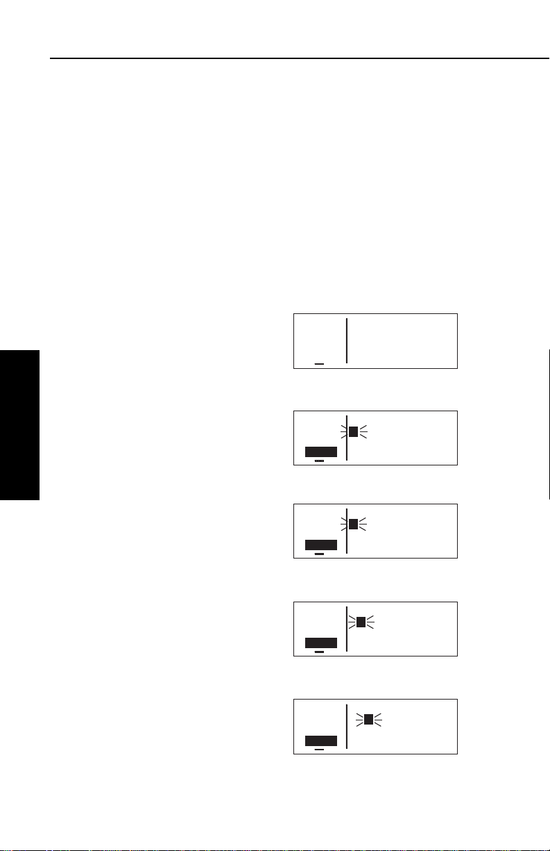
Basic GPS Operation
APT VOR NDB SUP ACT NAV FPL CAL SET OTH
ее.еnm CJS 116.70
ееееее JUAREZ CIUDAD
>Leg N 31°38.16'
CRSR W106°25.58'
APT VOR NDB SUP ACT NAV FPL CAL SET OTH
ее.еnm PNE 112.00
ееееее N PHILADELPHIA
>Leg N 40°04.92'
CRSR W 75°00.57'
APT VOR NDB SUP ACT NAV FPL CAL SET OTH
ее.еnm ABB 112.40
ееееее NABB
>Leg N 38°35.33'
CRSR W 85°38.16'
APT VOR NDB SUP ACT NAV FPL CAL SET OTH
ее.еnm ANX 114.00
ееееее NAPOLEON
>Leg N 39°05.73'
CRSR W 94°07.73'
APT VOR NDB SUP ACT NAV FPL CAL SET OTH
ее.еnm CJS 116.70
ееееее JUAREZ CIUDAD
>Leg N 31°38.16'
VOR 1 W106°25.58'
3.7.4. SELECTING WAYPOINTS BY NAME OR CITY
When you know the identifier of the desired waypoint you will use one
of the two methods just described to select it. However, what if you
know the name but you don’t know the identifier of your desired
waypoint? You’re in luck because the KLN 35A will allow you to
enter the first few characters of the name to help you find it in the
data base. We will use a couple of examples to illustrate how this is
done. For VORs and NDBs, you may use the navaid name. For airports, you may use the airport name or the city name (where the
airport is located).
In this first example we want to view the information in the KLN 35A
data base for Napoleon VOR (located just east of Kansas City) but
we don’t remember the identifier for it.
To select a VOR or NDB by navaid
name:
1. With the cursor off, use the right
knobs to select the VOR 1 page
(figure 3-75). The VOR waypoint
in view is not important.
2. Press B and then make sure
Chapter 3
Basic GPS Operation
the right inner knob is pushed to
the “in” position.
3. With the right outer knob, move
the cursor over the first character
in the VOR name which is being
displayed (figure 3-76).
Figure 3-75
Figure 3-76
4. Change this first character to an
“N” in this case (figure 3-77).
Figure 3-77
5. Move the cursor one space to the
right and select the second character, “A” (figure 3-78).
6. Select the third character, “P” (figure 3-79). Up pops Napoleon
and its identifier, ANX!
Figure 3-78
7. Turn off the cursor (B) so you
can view other pages.
Figure 3-79
Effective Date 5/95 006-08791-0000 Rev 0
3-24
Page 60
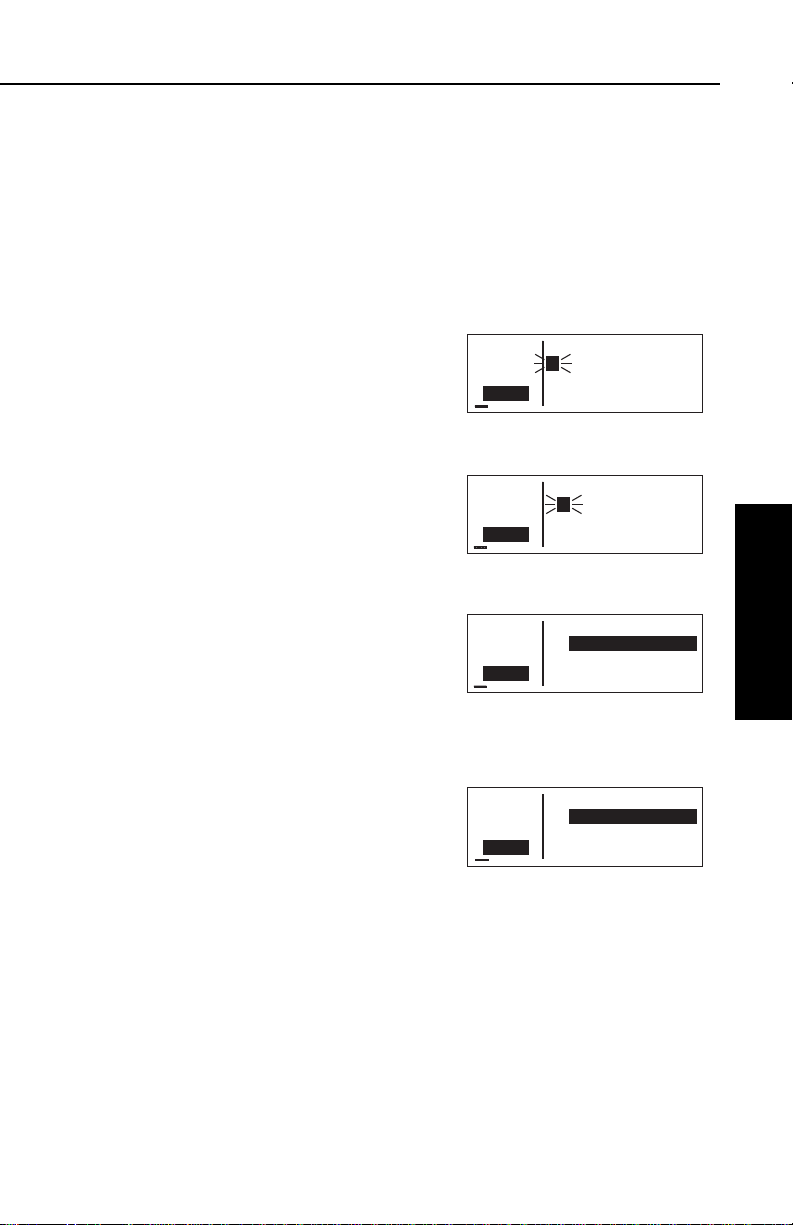
KLN 35A Pilot’s Guide Basic GPS Operation
APT VOR NDB SUP ACT NAV FPL CAL SET OTH
ее.еnm MGGT 4950ft
ееееее LA AURORA INTL
>Leg GUATEMALA CITY
CRSR GTM
APT VOR NDB SUP ACT NAV FPL CAL SET OTH
ее.еnm KLGA 20ft
ееееее LA GUARDIA
>Leg NEW YORK
CRSR NY
APT VOR NDB SUP ACT NAV FPL CAL SET OTH
ее.еnm KPAE 610ft
ееееее SNOHOMISH CO
>Leg EVERETT
CRSR WA
APT VOR NDB SUP ACT NAV FPL CAL SET OTH
ее.еnm MGGT 4950ft
ееееее LA AURORA INTL
>Leg GUATEMALA CITY
CRSR GTM
We will now use another example to show how we may enter a few
characters and then scan through all the waypoints in the data base
beginning with those characters. Let’s use this method to find
La Guardia Airport in New York City.
To select an airport by scanning the airport name:
1. With the cursor off and the right inner knob in the “in” position,
select the APT (Airport) 1 page. The airport displayed at this
time is not important.
2. Turn on the cursor (B).
3. Move the cursor over the first
character in the airport name
(figure 3-80).
4. Change the first character to an
“L”.
Figure 3-80
5. Move the cursor one place to the
right, and select an “A”
(figure 3-81).
6. Now, move the cursor one place
Figure 3-81
to the right and pull the right inner
knob out. The rest of the airport
name field will appear in inverse
video (figure 3-82).
7. Turn the right inner knob clock-
Figure 3-82
wise, scanning through
La Crosse Municipal, La
Grande/Union airport, and
several others. Eventually, you
will arrive at “LA GUARDIA”
(figure 3-83). By turning the cursor off, pushing the right inner
knob in and turning it, you can
Figure 3-83
leaf through the remainder of the
pages for La Guardia.
NOTE: This same method may be used with the name of the city
where the airport is located.
Basic GPS Operation
Chapter 3
3-25
Effective Date 5/95006-08791-0000 Rev 0
Page 61

Basic GPS Operation
APT VOR NDB SUP ACT NAV FPL CAL SET OTH
ее.еnm NEAREST
ееееее APT? VOR? NDB?
#>Leg SUP? SUA? FSS?
CRSR CTR?
There are a few changes made to names in order to accommodate
the KLN 35A display and to make the names easier to find.
1. Names which are too long to fit on the display are abbreviated.
The first six characters are usually exactly correct, but the follow
ing are exceptions:
North, Northern, East, Eastern, etc.—uses N, E
Southeast, Northwest, etc.—uses SE, NW
Point—uses PT
Port—uses PT
Fort—uses FT
Saint—uses ST
General—Deleted, or uses GEN
Person’s name—uses initials for other than last name unless
very well known (Will Rogers World airport)
Delete “City of” (City of Colorado Springs Municipal)
Delete “Greater” (Greater Buffalo Int’l)
Delete “The” (The Hartsfield Atlanta Int’l)
2. Unless the first word is greater than eight characters, it is usually
not abbreviated.
3. Delete most punctuation such as periods and apostrophes.
4. Abbreviations for International are INTL, INT, and IN.
Chapter 3
5. Abbreviations for Regional are REGL and REG.
Basic GPS Operation
3.8. “NEAREST” FUNCTIONS
At any time, you can have access to the nearest airports, waypoints,
Special Use Airspace (SUA), Flight Service Station (FSS) frequencies, and Center frequencies to your position. Your ticket to do this is
the handy G button.
When you first press the G button,
a page is displayed asking which
nearest function you would like to
select (figure 3-84).
Figure 3-84
Effective Date 5/95 006-08791-0000 Rev 0
3-26
Page 62

KLN 35A Pilot’s Guide Basic GPS Operation
APT VOR NDB SUP ACT NAV FPL CAL SET OTH
118.00 KPAO 1 1370ft
136.97 PALO ALTO-S CL
>Leg 2500ft HRD L
APT 1 >126°To 1.2nm
APT VOR NDB SUP ACT NAV FPL CAL SET OTH
118.00 KOAK 9 10ft
136.97 METRO OAKLAND
>Leg 10000ft HRD L
APT 1 >327°To 16.4nm
The choices are:
APT Airports
VOR VORs
NDB NDBs
SUP Supplemental (User-defined) waypoints
SUA Special Use Airspaces
FSS Flight Service Station Frequencies
CTR Center Frequencies
To select the desired nearest function, use the right outer knob to
move the cursor to the desired selection and press F. Notice that
the cursor is initially over the APT field, so you may press G then
press F immediately to access the nearest airports.
Selecting any of the waypoint types
(APT, VOR, NDB, or SUP) takes you
immediately to the waypoint page for
the first nearest waypoint of that type,
for example, the nearest airport (figure 3-85).
3.8.1. VIEWING THE NEAREST WAYPOINTS
Figure 3-85
Basic GPS Operation
Chapter 3
There are actually two waypoint scan lists for airports, VORs, NDBs
and user-defined waypoints. These two lists are the “complete” list
and the “nearest” list. The complete list contains all of the waypoints
in the data base for a waypoint type (all the airports, for example).
The nearest list consists of the nine nearest waypoints (of that type)
to your present position. Therefore, if you are in the nearest airport
list, it will contain the nine nearest airports relative to your location.
The nearest list is positioned in front of the complete list. That is,
instead of using the G button, you may scan backwards (turn the
right inner knob counterclockwise while in the “pulled-out” position)
through the complete list to reach the nearest list. You will know
when you have reached the nearest list because the top middle portion of the waypoint page will flash the relative position of the
waypoint to your position. “1” indicates nearest (figure 3-85) while “9”
indicates the ninth nearest
(figure 3-86). As you scan clockwise
with the right inner knob “1, 2, 3, ...,
9 ”, the next scan position is the
beginning of the complete list. The
3-27
Figure 3-86
Effective Date 4/97006-08791-0000 Rev 2
Page 63

Basic GPS Operation
APT VOR NDB SUP ACT NAV FPL CAL SET OTH
ее.еnm NEAREST APT
ееееее CRITERIA
>Leg Length: 2200'
SET 6 Surface: HRD
nearest list can only be reached by scanning backwards. It does not
wrap around after the last waypoint in the complete list.
Waypoint pages displayed in the nearest list do not contain a latitude
and longitude position as they do in the complete list. Instead, the
bearing and distance to the waypoint (or the radial and distance from
the waypoint) are displayed. In addition, nearest airport pages display the length, surface, and lighting of the longest runway. Once the
nearest waypoint is being displayed, the other waypoint pages (for
example, APT 2 and APT 3) for that airport are available for display
by making sure the right inner knob is pushed in and then turning it to
select the desired airport page.
3.8.1.1 Nearest Airport Criteria
The nine airports in the nearest list are the nine airports which meet
the criteria selected on the Setup 6 (SET 6) page. For example, you
probably wouldn’t want to take a turboprop into a 1500 foot grass
strip! The SET 6 page allows you to specify what criteria you want an
airport to meet before it is considered for the nearest airport list.
To specify the nearest airport criteria:
1. Select the SET 6 page and turn on the cursor (B).
2. Use the right inner knob to select
Chapter 3
Basic GPS Operation
the minimum length runway
desired for the airport to qualify
for the nearest airport list (figure
3-87). Values between 1000 feet
and 5000 feet in 100 foot increments may be selected.
Figure 3-87
3. Rotate the right outer knob clockwise to move the cursor over the
runway surface criteria.
4. Turn the right inner knob to select either HRD or ANY. If ANY is
chosen, then both hard and soft surface runways meeting the
required runway length will be included in the nearest airport list.
If HRD is chosen, then only hard surface runways will be included. Hard surface runways include concrete, asphalt, pavement,
tarmac, brick, bitumen, and sealed. Soft surface runways include
turf, gravel, clay, sand, dirt, ice, steel matting, shale, and snow.
For example, if the minimum runway criteria selected is 2200 feet in
length and HRD surface, then only airports having a hard surface
runway at least 2200 feet in length will be displayed in the nearest airport list.
Effective Date 5/95 006-08791-0000 Rev 0
3-28
Page 64
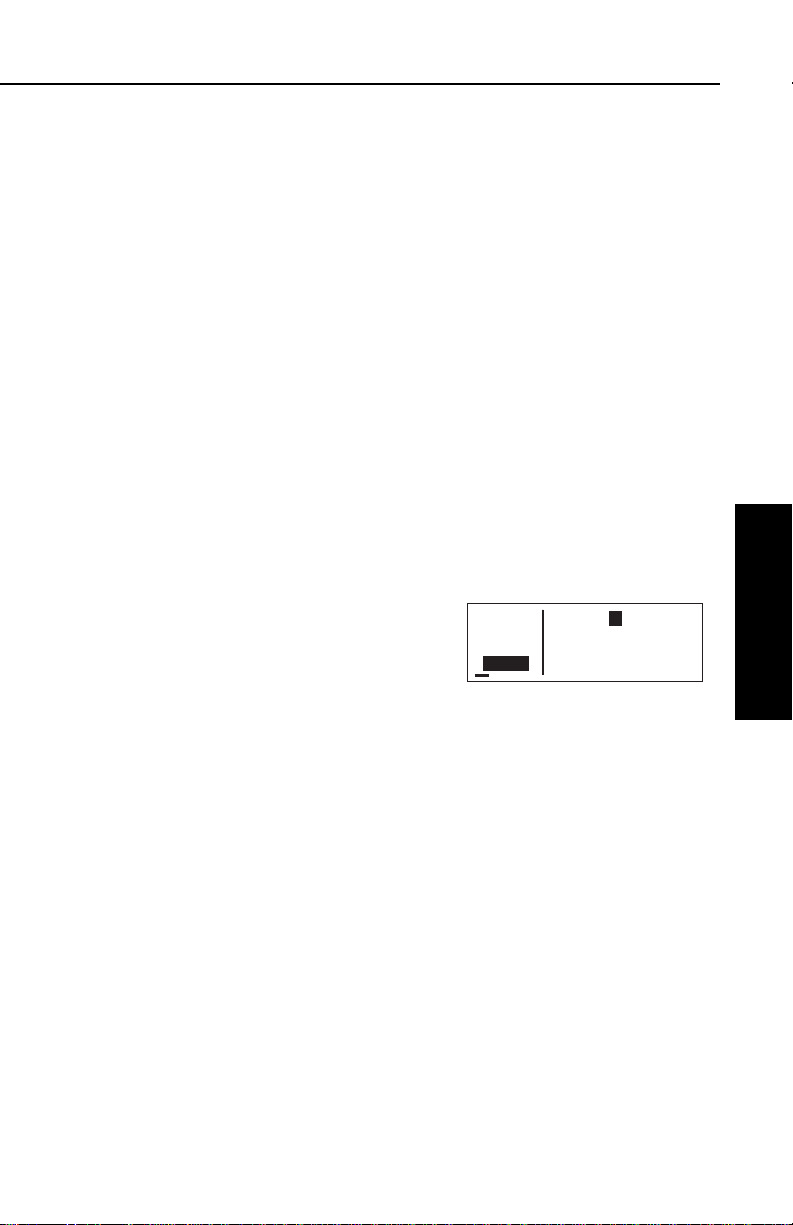
KLN 35A Pilot’s Guide Basic GPS Operation
APT VOR NDB SUP ACT NAV FPL CAL SET OTH
åå.ånm KPAO 1 1370ft
ееееее PALO ALTO-S CL
>Leg 2500ft HRD L
CRSR >126°To 1.2nm
3.8.1.2 Continuous Display of Nearest Airport
When the nearest airport page is initially displayed, “1” is displayed in
the upper right hand corner of the page to designate this airport as
the nearest airport. However, if you continue to fly along your flight
plan with this page selected, the same airport will be displayed and
its position in the nearest airport list will change from 1 to 2, 3, 4 ... 9
until finally it won’t be in the nearest airport list at all. The reason for
this is that in the event of an actual emergency once you have
determined which airport you are heading for, you don’t want the
nearest airport list to update while you are maneuvering or looking up
data on the other airport pages for that airport.
There may be times, however, when you’re flying over “unfriendly”
terrain when you wish to always have the nearest airport displayed
on the screen.
To display the nearest airport continuously:
1. Display the nearest airport page by pressing G followed by
pressing F.
2. Turn on the cursor (B).
3. Rotate the right outer knob
clockwise to position the cursor
over “1” (figure 3-88). As long as
the cursor is left in this position,
this page will update so that the
nearest airport is always shown
as the flight progresses.
3.8.2. VIEWING THE NEAREST SPECIAL USE AIRSPACES
The KLN 35A data base stores the locations of areas of special use
airspace (SUA). The types of SUA areas stored in the data base and
the abbreviations used to denote these areas are the following:
Class B Airspace CL B
Class C Airspace CL C
Control Area (used outside USA) CTA
Terminal Area (used outside USA) TMA
Alert Area ALRT
Danger Area DNGR
Prohibited Area PROH
Restricted Area REST
Terminal Radar Service Area TRSA
3-29
Basic GPS Operation
Chapter 3
Figure 3-88
Effective Date 5/95006-08791-0000 Rev 0
Page 65

Basic GPS Operation
The nearest special use airspace feature is constantly keeping track
of the five nearest areas of SUA. Pressing the Gbutton and
selecting the SUAoption will display
the SUA 1 page (figure 3-89) for the
nearest SUA to your location, including those which you are inside. Turn
to section 3.15 to learn more about
how an altitude input affects special
use airspace sensing and how the
KLN 35A determines if you are inside special use airspace or not.
The SUA 1 page displays the following information:
Line 1:The name of the special use airspace area.
Line 2:The SUA type (see the list of abbreviations above, this
particular SUA is Class B airspace), and the sequence number (1st
nearest, 2nd nearest, etc.).
Line 3:The altitude limits of the SUA.
Line 4:The proximity of the nearest point on the border of the SUA,
in the form of the absolute bearing, relative bearing, and distance to
the SUA border. The absolute bearing is the approximate heading
you would fly to most quickly get into the SUA. The relative bearing
arrow in the middle of this line points to the SUA border, telling you if
Chapter 3
it is directly ahead of you (
Basic GPS Operation
Finally, the distance to the SUA in nautical miles is displayed on the
), straight off your left wing (), etc.
right side of line 4.
ее.еnm KANSAS CITY
ееееее CL B 1
>Leg Below 8000ft
SUA 1 012° 9.3nm
APT VOR NDB SUP ACT NAV FPL CAL SET OTH
Figure 3-89
If the aircraft is inside the SUA, line 4 will read A/C INSIDE SUA, if
you are above or below the SUA, as indicated by the encoding
altimeter, line 4 will tell you this (A/C ABOVESUAor A/C BELOW
SUA).
A single clockwise turn of the right
inner knob selects the SUA 2 page,
which displays either the controlling
ATC facility (figure 3-90), or if the special use airspace is a Class B, Class
C, CTA, or TMA, the page will be displayed as in figure 3-91, instructing
you to press Eto see the APT 4
page (airport communications) for the
primary airport so that the correct
communications frequency may be
determined.
Effective Date 5/95 006-08791-0000 Rev 0
3-30
ее.еnm TRUMAN A
ееееее MOA 1
>Leg KC Center
SUA 2
APT VOR NDB SUP ACT NAV FPL CAL SET OTH
Figure 3-90
ее.еnm KANSAS CITY
ееееее CL B 1 INSIDE
>Leg Press CLR for
SUA 2 KMCI Freq Use
APT VOR NDB SUP ACT NAV FPL CAL SET OTH
Figure 3-91
Page 66

KLN 35A Pilot’s Guide Basic GPS Operation
APT VOR NDB SUP ACT NAV FPL CAL SET OTH
ее.еnm FT DODGE FSS
ееееее OMA VOR
>Leg Tx 122.10
FSS+1 Rec 116.30
APT VOR NDB SUP ACT NAV FPL CAL SET OTH
ее.еnm AUSTIN FSS
ееееее
>Leg 122.20
FSS+1 122.55
To scan through the remainder of the nearest SUA areas, pull the
right inner knob to the “out” position and turn it clockwise to view the
SUA pages for the second nearest through fifth nearest SUAs.
NOTE: The KLN 35A displays the five nearest SUAs regardless of
your present altitude and the altitude limits of the SUA. For instance,
it will include SUAs specified as “Below 6000ft” even if you are cruising at 10,000 feet.
3.8.3. Viewing the Nearest Flight Service Station Frequencies
The KLN 35A stores in its data base the locations of Flight Service
Stations (FSS) and their remote communications sites. In addition,
the KLN 35A determines which two of these FSS points of communication are closest to your present location. What a convenience for
you! Next time you want to file a flight plan from the air or contact an
FSS for some other reason, you can easily use the KLN 35A to determine a suitable FSS and the appropriate frequency.
NOTE: In some areas of the world the KLN 35A provides the location of the nearest point of communication with a facility providing
information (INF) or radio (RDO) services.
Pressing the G button and selecting the FSS option will display two
of the nearest points of communication with Flight Service Stations.
There will normally be two FSS 1 pages, one for each of the two
points of contact. The name of the FSS is at the top of the page.
There can be from one to three frequencies included for a point of
contact (figure 3-92). Remember that
in the U.S. the frequency 122.00 MHz
is used for “Flight Watch” and the frequency 123.60 MHz is used for
Aeronautical Advisory Service. As
you know, it is often possible to communicate with an FSS by transmitting
on 122.10 MHz and listening on the
VOR frequency. In cases like this,
the FSS 1 page displays the frequencies to use for transmit and receive
and also the name of the VOR
through which you are communicating (figure 3-93).
Figure 3-92
Figure 3-93
Basic GPS Operation
Chapter 3
3-31
Effective Date 5/95006-08791-0000 Rev 0
Page 67

Basic GPS Operation
3.8.4. Viewing the Nearest Center Frequencies
The KLN 35A also stores in its data base the low altitude boundaries
of each of the ARTCC “Centers”. The KLN 35A determines the proper Center to contact and the appropriate frequencies to use for the
aircraft’s present position. Pressing the Gbutton and selecting the
CTRoption will display this information to you (figure 3-94). Next time
you wish to obtain VFR flight following
or communicate with Center for any
reason, you have a quick way to get a
frequency for establishing contact!
Appendix D contains a listing of
Center abbreviations used on the CTR page.
NOTE: Frequencies for Area Control Centers are displayed on the
CTR page for some areas of the world.
3.9. DIRECT TO OPERATION
The Dbutton is used to initiate Direct To operation (navigation from
Chapter 3
your present position direct to your
destination). When Dis pressed,
Basic GPS Operation
the Direct To page will be displayed
with a flashing cursor over a waypoint
identifier (figure 3-95). The waypoint
identifier which appears on the Direct
To page is chosen by the KLN 35A
according to the following rules:
ее.еnm LOS ANGELES CTR
ееееее 118.55
>Leg 132.85
CTR
APT VOR NDB SUP ACT NAV FPL CAL SET OTH
Figure 3-94
ее.еnm DIRECT TO:
ееееее
#>Leg KPWA
CRSR
APT VOR NDB SUP ACT NAV FPL CAL SET OTH
Figure 3-95
1. If the Flight Plan 0 (FPL 0) page is displayed on the screen and
the cursor is over one of the waypoint identifiers in FPL 0 when
D
is pressed, then that waypoint identifier will appear on the
DIR page. You will appreciate this feature when you learn to use
flight plans in section 4.2.
2. If the KLN 35A is displaying the NAV 4 page and the right inner
knob is in the “out” position, then the waypoint highlighted in the
lower right hand corner of the NAV 4 map display will be the
default waypoint. You will also find this feature useful when operating from the active flight plan.
OR . . .
Effective Date 5/95 006-08791-0000 Rev 0
3-32
Page 68

KLN 35A Pilot’s Guide Basic GPS Operation
3. If there is any waypoint page (APT, VOR, NDB, SUP, or ACT
page) in view when Dis pressed, then the DIR page will
contain the identifier for the waypoint just viewed.
If none of the conditions above is occurring, then:
4. When
D
is pressed, the waypoint identifier for the current
active waypoint will be displayed on the DIR page.
If there is no active waypoint when Dis pressed, then:
5. The Direct To page displays blanks in the waypoint identifier
field. In order for there not to be an active waypoint, there is no
Direct To waypoint and there are no waypoints in Flight Plan 0.
3.9.1. INITIATING A DIRECT TO
Now that you know the ground rules, let’s go ahead and try some
practical examples. First, let’s say we wanted to fly directly to
Wexford County Airport in Cadillac, Michigan. Its ICAO identifier is
KCAD.
To fly Direct To a waypoint (procedure 1):
1.Press D. The Direct To page is
displayed (figure 3-96). The
cursor will already be on. A
waypoint identifier may or may
not be displayed, it doesn’t matter
at this point.
ее.еnm DIRECT TO:
ееееее
#>Leg KDTW
CRSR
APT VOR NDB SUP ACT NAV FPL CAL SET OTH
Figure 3-96
2.Rotate the right inner knob to
select the first character of the
desired waypoint’s identifier, in
this case, a “K” (figure 3-97).
Remember to enter the “K”, “C”,
or “P” prefix for certain airports in
North America, if required (see
ее.еnm DIRECT TO:
ееееее
#>Leg K
CRSR
APT VOR NDB SUP ACT NAV FPL CAL SET OTH
Figure 3-97
section 2.3, “ICAO Identifiers”).
Basic GPS Operation
Chapter 3
3.Turn the right outer knob one
click clockwise to move the flashing portion of the cursor over the
second character position
(figure 3-98).
3-33
ее.еnm DIRECT TO:
ееееее
#>Leg K
CRSR
APT VOR NDB SUP ACT NAV FPL CAL SET OTH
Figure 3-98
Effective Date 5/95006-08791-0000 Rev 0
Page 69

Basic GPS Operation
4.Rotate the right inner knob to
select the second character of the
identifier (figure 3-99).
5.Use right outer and inner knobs
as in the previous steps until the
desired identifier is completely
displayed (figure 3-100).
6.Press Fto display the waypoint
page for the selected waypoint
(figure 3-101).
7.Press Fagain to approve the
displayed waypoint page. The
screen will change to the NAV 1
page, and the selected waypoint
will now be the active Direct To
Chapter 3
Basic GPS Operation
waypoint (figure 3-102).
ее.еnm DIRECT TO:
ееееее
#>Leg KC2
CRSR
APT VOR NDB SUP ACT NAV FPL CAL SET OTH
Figure 3-99
ее.еnm DIRECT TO:
ееееее
#>Leg KCAD
CRSR
APT VOR NDB SUP ACT NAV FPL CAL SET OTH
Figure 3-100
åå.ånm KCAD 1310ft
ееееее WEXFORD CO
#>Leg CADILLAC
APT 1 MI
APT VOR NDB SUP ACT NAV FPL CAL SET OTH
Figure 3-101
76.8nm D∆ KCAD
121kt > ««««∑∏π««««
>Leg DTK167° TK168°
NAV 1 >167°To 0:41
APT VOR NDB SUP ACT NAV FPL CAL SET OTH
∫
Figure 3-102
To fly Direct To a waypoint (procedure 2):
1.Select the desired waypoint page
(APT, VOR, NDB, or SUP) on the
screen (figure 3-103) using one of
the three procedures explained in
section 3.9.
åå.ånm JJC 396
ееееее MOUNTAIN CITY
>Leg N 36°24.99'
CRSR W 81°49.46'
APT VOR NDB SUP ACT NAV FPL CAL SET OTH
Figure 3-103
2.Press D. The Direct To page is
displayed and it contains the
desired waypoint identifier
(figure 3-104).
ее.еnm DIRECT TO:
ееееее
#>Leg JJC
CRSR
APT VOR NDB SUP ACT NAV FPL CAL SET OTH
Figure 3-104
3.Press F. The display will revert to the NAV 1 page with the
selected waypoint as the Direct To waypoint.
Effective Date 5/95 006-08791-0000 Rev 0
3-34
Page 70
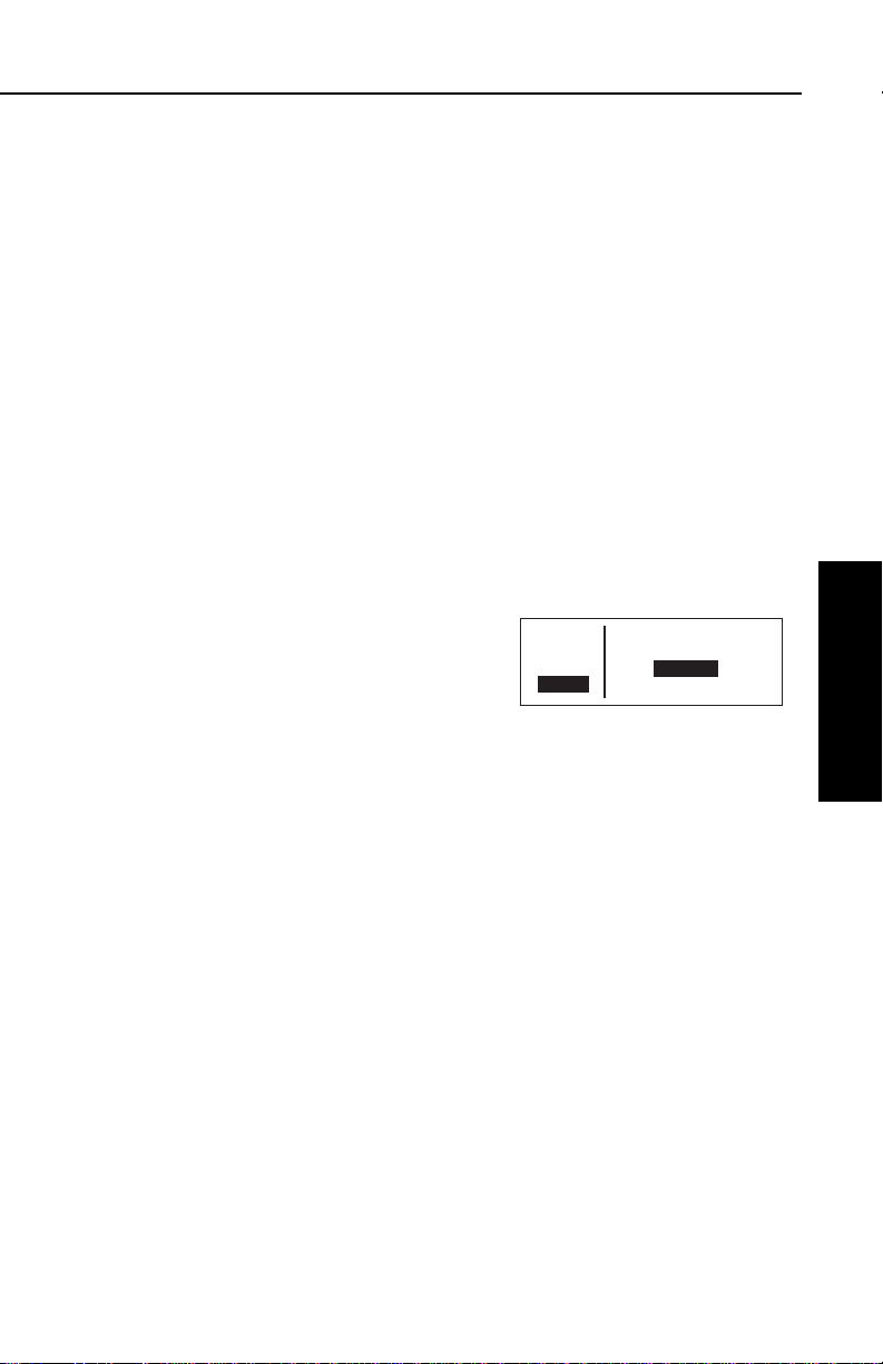
KLN 35A Pilot’s Guide Basic GPS Operation
If you get off course and wish to recenter the left/right deviation bar
(D-Bar) to proceed to the same waypoint, use the following
procedure:
To recenter the D-Bar by going direct to the active waypoint:
1.Select a non-waypoint page (NAV, FPL, CAL, SET, or OTH) on
the screen.
2.Press D. The Direct To page is displayed on the left, containing the active waypoint identifier.
3.Press F.
3.9.2. CANCELING A DIRECT TO
To cancel Direct To operation:
The primary reason for wanting to cancel Direct To operation is to
return to flight plan operation which is described later in section 4.2.4
“Combining Direct To and Flight Plan Operation”.
1.Press D.
2.Press Eto blank out the waypoint identifier field (figure 3-105).
3.Press F.
ее.еnm DIRECT TO:
ееееее
>Leg _____
CRSR
APT VOR NDB SUP ACT NAV FPL CAL SET OTH
Figure 3-105
Basic GPS Operation
Chapter 3
3.9.3. WAYPOINT ALERTING FOR DIRECT TO OPERATION
Approximately 36 seconds prior to reaching a Direct To waypoint, the
arrow preceding the waypoint identifier on the waypoint page for the
active waypoint will begin flashing. This arrow will also be flashing on
any NAV or FPL page displaying the active waypoint identifier. This
is called “waypoint alerting”. If an external waypoint alert annunciator
is mounted in the aircraft, this annunciator will begin flashing at the
same time.
3-35
Effective Date 5/95006-08791-0000 Rev 0
Page 71

Basic GPS Operation
3.10. NAVIGATION PAGES
As you would expect, the NAV (navigation) pages contain information
relating specifically to the KLN 35A’s navigation capabilities. The
KLN 35A has four NAV pages. The procedure for selecting specific
pages, including the NAV pages, was described in section 3.4.1,
“Page Selection”.
3.10.1. THE NAVIGATION 1 (NAV 1) PAGE
The NAV 1 page is the primary
navigation display, and is shown in
figure 3-106. In normal flight, you will
probably want to view this page quite
often. A NAV 1 page displays the fol-
66.1nm ∂∆ KAUG
132kt > ««««∑∏π««««
>Leg DTK048° TK046°
NAV 1 >047°To 0:30
APT VOR NDB SUP ACT NAV FPL CAL SET OTH
Figure 3-106
lowing information:
Line 1:The active navigation leg.
For Direct To operation this consists
of the Direct To symbol,
∂∂∆∆
, followed
by the active Direct To waypoint identifier (figure 3-106). For the leg of a
flight plan this consists of the “from”
waypoint identifier and the active “to”
Chapter 3
waypoint identifier (figure 3-107). An arrow ∆∆precedes the active
waypoint identifier.
Basic GPS Operation
ее.еnm KBGR ∆ KAUG
ееееее > ««««∑∏π««««
>Leg DTK237° TK233°
NAV 1 >234°To 0:22
APT VOR NDB SUP ACT NAV FPL CAL SET OTH
FIgure 3-107
Line 2:A cyclic field which can either be (1) a course deviation
indicator (CDI) that graphically displays left and right deviation from
desired track (figure 3-107), or (2)
The direction to fly to intercept the
desired track and the crosstrack
distance (figure 3-108). In either
case, the same information is
displayed. This is a cyclic field, so
you can change back and forth from
ее.еnm KBGR ∆ KAUG
ееееее >Fly L 0.4nm
>Leg DTK237° TK233°
NAV 1 >234°To 0:22
APT VOR NDB SUP ACT NAV FPL CAL SET OTH
Figure 3-108
∫
∫
the two options by turning on the cursor (B) over the second line
and pressing the E button.
The CDI’s vertical bar operates like a navigation deviation needle on
a conventional CDI or HSI using VOR/Localizer navigation. An oncourse indication is displayed when the vertical deviation bar is
centered on the triangle in the middle of the CDI. In both modes (Leg
and OBS, see section 4.5), each dot represents one nautical mile
Effective Date 5/95 006-08791-0000 Rev 0
3-36
Page 72

KLN 35A Pilot’s Guide Basic GPS Operation
APT VOR NDB SUP ACT NAV FPL CAL SET OTH
ее.еnm KBGR ∆ KAUG
ееееее > ««««“‘∫««««
>Leg DTK232° TK233°
NAV 1 >234°To 0:02
APT VOR NDB SUP ACT NAV FPL CAL SET OTH
--.-nm
------ > ««F«L A«G««
>Leg DTK---° TK---°
NAV 1 >---°To --:--
KBGR
KAUG
2 NM
KBGR ∆ KAUG
> ««««∑∏π∫«««
DTK232° TK233°
>234°To 0:02
APT VOR NDB SUP ACT NAV FPL CAL SET OTH
--.-nm
------ >Fly - --.-nm
>Leg DTK---° TK---°
NAV 1 >---°To --:--
APT VOR NDB SUP ACT NAV FPL CAL SET OTH
ее.еnm KBGR ∆ KAUG
ееееее >Fly R 13.1nm
>Leg DTK232° TK233°
NAV 1 >234°To 0:22
deviation from the desired track. Therefore, the CDI shows course
deviation five nautical miles left and right of course. A vertical deviation bar positioned two dots to the right of the center triangle indicates
the aircraft is two nautical miles to the left of course (figure 3-109).
Figure 3-109
The center triangle also serves as the CDI’s TO/FROM indicator and
operates in the same manner as a
conventional CDI TO/FROM indicator; a triangle pointing up indicates
“to” the active waypoint while a
“down” triangle (figure 3-110)
indicates “from” the active waypoint.
The word FLAG is displayed over
the CDI when the KLN 35A is not
usable for navigation (figure 3-111).
Figure 3-110
Basic GPS Operation
Chapter 3
The numerical crosstrack distance
display is especially handy when
more than five nautical miles off of
course (naturally, you yourself
would never deviate more than five
nm off course, but not everyone is
as good a pilot as you are!) If your
crosstrack distance was 13.1 nautical miles left of course, the graphic
CDI needle will be pegged on the
right side (which doesn’t tell you
much). But this presentation will
show you exactly how far off course
you are (figure 3-112). When the
KLN 35A is not usable for navigation, the crosstrack distance will be
3-37
Figure 3-111
Figure 3-112
Figure 3-113
Effective Date 5/95006-08791-0000 Rev 0
Page 73

Basic GPS Operation
dashed out (figure 3-113).
Line 3:Magnetic desired track, and magnetic actual track (see
Appendix A for navigation terms). In normal on-course flight, it is
desirable to steer the aircraft to keep these two numbers equal.
Line 4:A cyclic field which can display either bearing to the active
waypoint (To) or radial from the active waypoint (Fr) relative to the
present position. By placing the cursor over this field and pressing
the Ebutton, you may toggle between the two options.
NOTE: Due to “great circle” courses and magnetic variation differences between present position and the active waypoint, the To
bearing and From radial may not be exactly 180° different from each
other when the system is in the Leg mode. This condition is most
likely to occur when long distances are involved, and/or you are
operating in very northerly or southerly latitudes. See figure 3-114 for
an example depicting a case like this. The aircraft is somewhere over
Georgia, and the active waypoint is KPHX. The bearing to steer is
269°, and radial is 72°. Generally, you will want to use bearing (not
radial) when long distances are involved.
Chapter 3
Basic GPS Operation
N
72°
KPHX
N
269°
Figure 3-114
Line 4 also displays the estimated time en route (ETE) from present
Effective Date 5/95 006-08791-0000 Rev 0
3-38
Page 74

KLN 35A Pilot’s Guide Basic GPS Operation
APT VOR NDB SUP ACT NAV FPL CAL SET OTH
ее.еnm >Present Posn
ееееее
>Leg Ref: KMKC
NAV 2 219°Fr 22.2nm
APT VOR NDB SUP ACT NAV FPL CAL SET OTH
ее.еnm >Present Posn
ееееее
>Leg N 38°53.74'
NAV 2 W 94°53.39'
APT VOR NDB SUP ACT NAV FPL CAL SET OTH
ее.еnm >Present Posn
ееееее
>Leg Ref: OJC
NAV 2 310°Fr 9.5nm
APT VOR NDB SUP ACT NAV FPL CAL SET OTH
ее.еnm >Present Posn
ееееее
>Leg Ref: OJC
CRSR 346°Fr 28.6nm
position to active waypoint.
3.10.2. THE NAVIGATION 2 (NAV
2) PAGE
The NAV 2 pages in figures 3-115
and 3-116 display the aircraft’s
present position in one of two
formats. The first line is a cyclic field
which allows you to toggle between
formats. When the NAV 2 page is
first displayed, it defaults to present
position in terms of the radial and
distance from a nearby VOR. You
can change the reference waypoint from the nearby VOR to any
waypoint.
To change the NAV 2 page present
position reference waypoint:
1. With the NAV 2 page on the
radial and distance from a
reference waypoint format, turn
on the cursor (B) and move it to the Ref: field (figure 3-117).
Figure 3-115
Figure 3-116
Figure 3-117
Basic GPS Operation
Chapter 3
2. Use the right inner and outer knobs to enter the waypoint you
wish to use as a reference.
3. Press F. The waypoint page
for the identifier just entered will
be displayed.
4. If this is the waypoint you intended, press F again. The display
will return to the NAV 2 page
(figure 3-118).
NOTE: If you change the reference waypoint, change to a page
other than the NAV 2 page, then turn back to the NAV 2 page, the
reference waypoint will revert back to a nearby VOR.
3-39
Figure 3-118
Effective Date 5/95006-08791-0000 Rev 0
Page 75

Basic GPS Operation
APT VOR NDB SUP ACT NAV FPL CAL SET OTH
ее.еnm Time CDT 1605
ееееее Depart 1343
>Leg ETA KIXD 1710
NAV 3 Flight 2:22
25.8nm
SGJ
{>Leg
>117kt
APT VOR NDB SUP ACT NAV FPL CAL SET OTH
100
KJAX
"
SGJ
OMN
KCVN
%
%
%
%
By turning on the cursor (B) over the first line and pressing E,
you can change to the latitude and
longitude format.
3.10.3. THE NAVIGATION 3 (NAV
3) PAGE
The Navigation (NAV) 3 page shows
you several important times pertaining to your flight (figure 3-119).
Line 1: The current system time zone and time. The time zone may
be changed by turning the cursor (B) on over it and turning the
right inner knob. All times shown on the NAV 3 page are in terms of
the system time zone (except for the flight time, which is an elapsed
time).
Line 2: The time of departure. This is the time when a valid groundspeed was first greater than 30 knots (typically during takeoff).
Line 3: Estimated time of arrival at your destination. If the active
waypoint is not part of the active flight plan, the active waypoint will
be the destination. Otherwise, the last waypoint in your active flight
plan will be the destination.
Line 4: The elapsed flight time, which will be the hours and minutes
Chapter 3
since the departure time.
Basic GPS Operation
3.10.4. THE NAVIGATION 4 (NAV 4) PAGE
Figure 3-119
The NAV 4 page is a graphical moving map which offers excellent
“bird’s-eye-view” situational awareness to you as the pilot in command. This page can show you where you are and where you’re
headed relative to your active flight
plan or leg, your destination waypoint(s), the nearby airports and
VORs, and even the boundaries of
nearby special use airspace!
The NAV 4 page (figure 3-120) is a lit-
Figure 3-120
tle bit different than some of the other
KLN 35A pages. Instead of displaying the page type and number
(i.e. NAV 4) in the lower left corner of the screen, an additional piece
of navigation data is displayed here. We’re willing to bet you’ll know
Effective Date 5/95 006-08791-0000 Rev 0
3-40
Page 76

KLN 35A Pilot’s Guide Basic GPS Operation
25.8nm
SGJ
{>Leg
>117kt
APT VOR NDB SUP ACT NAV FPL CAL SET OTH
100
KJAX
"
SGJ
OMN
KCVN
%
%
%
%
this is the NAV 4 page anyway, because of its unique graphics.
The left side of the screen displays the distance to go, active way-
point identifier, and mode annunciation (either Leg, or the OBS
selected course), just like it usually would, but the fourth line is a
cyclic field for which you may select:
Magnetic Desired Track (degrees) DTK123
Groundspeed (knots) 123kt
Estimated Time Enroute (hours:minutes) 1:23
Crosstrack Correction (nautical miles) 1.23→
NOTE: Magnetic desired track may only be selected when KLN 35A
is in the Leg navigation mode. When the KLN 35A is in the OBS
mode, the “desired track” is the same as the OBS selected course
displayed on line 3.
To change the data displayed in this
cyclic field, simply turn on the cursor
(B ), rotate the right outer knob
counterclockwise to position the cursor over this field (figure 3-121), and
press the E button to choose the desired information.
Figure 3-121
Basic GPS Operation
Chapter 3
Now we move on to the map display area on the right side of the
screen. In all KLN 35A installations there are three common map orientation formats that may be selected on the NAV 4 page: a True
North up display, a desired track up display, or an actual track up display. When the North up display is selected, viewing the NAV 4 page
is like looking at a navigation chart with North at the top. When the
desired track up display is selected the NAV 4 page is like looking at
a chart that is turned so that your course line is always pointing up.
When the actual track up display is selected, viewing the NAV 4 page
is like looking at a chart that is turned so that the direction the aircraft
is tracking over the ground is pointing up. In a no-wind condition,
actual track is identical to the aircraft’s heading.
CAUTION: When using the actual track up format it is typical for
there to be a slight delay from the time a heading change is
made until the correct map orientation is displayed. Be careful
when using either the desired track up display or the actual
track up display to not think that a heading up display is being
used.
3-41
Effective Date 4/97006-08791-0000 Rev 2
Page 77

Basic GPS Operation
When you are navigating with a flight plan (see section 4.2), the NAV
4 page displays the waypoints of the active flight plan (FPL 0) with
their waypoint identifiers (figure 3-121). Course lines connect the
flight plan waypoints.
When operating Direct To a waypoint
which is not in the active flight plan,
the direct to waypoint is shown on the
map, and although the waypoints of
the active flight plan are still shown on
the screen, they are not connected by
28.0nm
2CB
{>Leg
>117kt
APT VOR NDB SUP ACT NAV FPL CAL SET OTH
ORL
%
2CB
%
OMN
%
60
SGJ
Figure 3-122
course lines (figure 3-122).
In the lower left corner of the map display area is the map range
scale in nautical miles. The range scale indicates the distance from
the aircraft’s position to the top of the screen. You may select a
range scale of 1 NM to 500 NM with several choices in between by
turning on the cursor (B), and using
the right inner knob to select the
desired range scale. For example,
figure 3-123 illustrates the results of
changing the range scale of the map
in figure 3-122 from 60 nautical miles
to 30 nautical miles.
Chapter 3
Additionally, there is a choice called AUTO, for automatic range scaling. This choice is sandwiched between the 1 NM scale and the 500
Basic GPS Operation
24.2nm
2CB
{>Leg
>117kt
APT VOR NDB SUP ACT NAV FPL CAL SET OTH
Figure 3-123
%
30
%
SGJ
2CB
NM scale, such that it is “below” 1 NM and “above” 500 NM. The
AUTO scale factor feature “zooms” the map in and out in a useful
way so that you don’t have to. Specifically, AUTO chooses the smallest map scale that will display the active waypoint and, if there is one,
the waypoint after the active waypoint. Choosing the AUTO scale
factor means there is one less item for you to worry about.
%
KJAX
"
%
%
KJAX
"
%
Aside from changing the map range
scale, all other customization of the
map display is done from the menu.
Notice that when you turn on the cursor (B), the Menu?field appears
above the range scale. Turn the right
outer knob one step counter-clockwise to move the cursor over the
Menu?field (figure 3-124) and press
F. The menu now “pops-up” on the
screen (figure 3-125).
17.6nm
SGJ
{>Leg
>117kt
APT VOR NDB SUP ACT NAV FPL CAL SET OTH
Menu?
60
SGJ
KJAX
%
OMN
%
"
%
ORL
%
KORL
Figure 3-124
17.6nm
SGJ
{>Leg
>117kt
APT VOR NDB SUP ACT NAV FPL CAL SET OTH
SUA:off
VOR:off
APT:off
112°
KJAX
%
OMN
GJ
%
"
%
ORL
%
KORL
Figure 3-125
Effective Date 5/95 006-08791-0000 Rev 0
3-42
Page 78

KLN 35A Pilot’s Guide Basic GPS Operation
To select the desired NAV 4 orientation, you must first select the menu,
then use the right outer knob to position the cursor over the map
orientation field (figure 3-126). Rotate
the right inner knob to display N↑for
North up, DTK↑for desired track up
(figure 3-127) or TK↑for actual track
up. If the cursor is located on a field
other than the map orientation field,
then the DTK↑or TK↑annunciation
is replaced with the actual value. The
123°displayed in figure 3-128 shows
how the actual track is displayed
when the cursor is not over the map
orientation field.
Actual track up display is usually preferred for use in flight. However, the
track up display is only usable when
the aircraft is moving 2 knots or more
so the North up display may be a good choice if you are stationary.
Notice that in both the North up format and the desired track up format, the aircraft’s position is depicted by a diamond. In the actual
track up format, the aircraft’s position is depicted by an aircraft symbol.
17.6nm
SGJ
{>Leg
>117kt
APT VOR NDB SUP ACT NAV FPL CAL SET OTH
SUA:off
VOR:off
APT:off
TK
KJAX
GJ
%
OMN
%
"
%
ORL
%
KORL
Figure 3-126
17.6nm
SGJ
{>Leg
>117kt
APT VOR NDB SUP ACT NAV FPL CAL SET OTH
SUA:off
VOR:off
APT:off
DTK
KJAX
GJ
%
OMN
%
"
%
ORL
%
KORL
Figure 3-127
17.6nm
SGJ
{>Leg
>117kt
APT VOR NDB SUP ACT NAV FPL CAL SET OTH
SUA:off
VOR:off
APT:off
123°
KJAX
GJ
%
OMN
%
"
%
ORL
%
KORL
Figure 3-128
Basic GPS Operation
Chapter 3
You may choose to have nearby airports, VORs, and special use airspace (SUA) displayed on the moving map! To do so, use the
pop-up menu by turning on the cursor and selecting Menu?.
When the menu is first displayed the cursor will be on the SUA selection field. Rotate the right inner knob to select onor off. When SUAs
are selected, the five nearest SUAs are displayed. However, they will
not be displayed on map range scales larger than 160 NM. Special
use airspace areas are displayed regardless of your altitude relative
to the airspace. The nearest SUA feature (section 3.8.2) and the
SUA alerting feature (section 3.15) will indicate the altitude limits of
the airspace to you. Section 3.15 will also help you understand more
about the KLN 35A special use airspace features as well as the types
of SUA that are included in the KLN 35A data base.
NOTE: Only the outer lateral boundaries are displayed for Class B,
Class C, CTA, and TMA airspace. The actual SUA may have different lateral limits (i.e. smaller) depending on your present altitude.
3-43
Effective Date 5/95006-08791-0000 Rev 0
Page 79

Basic GPS Operation
17.6nm
SGJ
{>Leg
>117kt
APT VOR NDB SUP ACT NAV FPL CAL SET OTH
SUA:on
VOR:off
APT:on
123°
KJAX
"
KORL
OMN
%
%
%
%
ORL
GJ
SGJ
17.6nm
SGJ
{>Leg
>117kt
APT VOR NDB SUP ACT NAV FPL CAL SET OTH
25
"
KNIP
SGJ
%
2CB
#
#
17.6nm
SGJ
{>Leg
>117kt
APT VOR NDB SUP ACT NAV FPL CAL SET OTH
SUA:on
VOR:off
APT:on
123°
KJAX
"
KORL
OMN
%
%
%
%
ORL
GJ
In the same manner, the nearest VORs and/or airports may be
selected by first using the right outer
knob to move the cursor over the
VOR or APT selection field and then
using the right inner knob to select on
or off. The example in figure 3-129
shows SUAs and airports having
been selected.
When the desired selections have
been made, press the B button to
remove the menu from the screen
(figure 3-130). Notice that the nearest
airports are depicted with a small
##
symbol, while the VORs are shown as
a small box ($$).
One last item of interest on this page: you may change the active
waypoint to any of the flight plan waypoints without having to leave
the map display. This is done by pulling the right inner knob to the
“out” or “scan” position. This will cause the identifier for the active
waypoint to be displayed in the bottom right corner of the screen
(figure 3-131). The waypoint
displayed in this area will be the
default waypoint when D is
Chapter 3
pressed. By turning the right inner
Basic GPS Operation
knob it is possible to scan through the
waypoints of the active flight plan
(FPL 0). Turning the knob clockwise
will scan through the waypoints in sequence until the end of the flight
plan is reached. Turning the knob counter-clockwise will scan
through the active flight plan in reverse order until the beginning of
the flight plan is reached. Pushing the right inner knob back to the
“in” position will remove this text from the map display area.
Figure 3-129
Figure 3-130
Figure 3-131
The following hints will make using the NAV 4 page more enjoyable.
• It is easy to clutter the display with so much data that it is unusable. Select a range scale that allows an uncluttered
presentation of the chosen SUAs, VORs, and airports. Or,
select another combination of these from the menu.
Experiment and continue to make new selections for different
phases of your trip.
3-44
Effective Date 5/95 006-08791-0000 Rev 0
Page 80

KLN 35A Pilot’s Guide Basic GPS Operation
•Press Eto instantly declutter the SUA, VOR, and airport
selections from the graphics display. Flight plan and Direct To
waypoints will still be displayed. Press Eagain to restore the
selections.
CAUTION: The NAV 4 page does not display weather, terrain, or
other data.
3.11. WAYPOINT PAGES
NOTE: Each of the waypoint page types includes a cyclic field which
displays present magnetic bearing to or magnetic radial from the
waypoint. Due to “great circle” courses and magnetic variation
differences between present position and the active waypoint, the To
bearing and From radial may not be exactly 180° different from each
other. This condition is most likely to occur when long distances are
involved, and/or you are operating in very northerly or southerly
latitudes. See section 3.10.1 and figure 3-114 for more details.
Basic GPS Operation
3.11.1. AIRPORT PAGES
3.11.1.1. The Airport 1 (APT 1) Page
See figure 3-132.
Line 1:The ICAO identifier (see
section 2.3) of the airport; an arrow
precedes the identifier if it is the
active waypoint. The airport elevation
above MSL in feet, which is rounded
to the nearest 10 feet.
ее.еnm KLIT 260ft
ееееее ADAMS
>Leg LITTLE ROCK
APT 1 AR
APT VOR NDB SUP ACT NAV FPL CAL SET OTH
Figure 3-132
Line 2:The name of the airport.
Line 3:The city where the airport is located.
Line 4:The State if the airport is
located in the U.S., the Province if
located in Canada, or the country if
outside the U.S. and Canada. A listing of the abbreviations used for
States, Provinces, and countries is
contained in Appendix D. The right
ее.еnm KSZL 870ft
ееееее WHITEMAN AFB
>Leg KNOB NOSTER
APT 1 MO MILITARY
APT VOR NDB SUP ACT NAV FPL CAL SET OTH
Figure 3-133
side of line 4 will read MILITARYif it
is a military airport (Figure 3-133) or PRIVATEif it is a private-use
airport.
Chapter 3
3-45
Effective Date 5/95006-08791-0000 Rev 0
Page 81

Basic GPS Operation
If the airport is being viewed as part of
the
nearest airports list
(see section
3.8.1, “Viewing the Nearest
Waypoints”), the APT 1 page format
will differ as follows (see figure 3-
134):
ее.еnm KLIT 3 260ft
ееееее ADAMS
>Leg 7200ft HRD L
APT 1 >103°To 14.5nm
APT VOR NDB SUP ACT NAV FPL CAL SET OTH
Figure 3-134
Line 1:After the airport identifier, the number designating the airport’s position in the nearest airport list is displayed. In figure 3-134,
KLIT is the third nearest airport.
Line 2:Same as a normal APT 1 page.
Line 3:The length, surface, and lighting of the longest runway.
Line 4:The magnetic bearing to or the magnetic radial from the
airport and the distance in nautical miles. Placing the cursor over the
radial/bearing field and pressing Etoggles between radial from and
bearing to the airport.
3.11.1.2. The Airport 2 (APT 2) Page
See figure 3-135.
Line 1:The ICAO identifier (see
section 2.3) of the airport; an arrow
Chapter 3
precedes the identifier if it is the active
waypoint.
Basic GPS Operation
ее.еnm KLIT
ееееее N 34°43.74'
>Leg W 92°13.47'
APT 2 >103°To 14.5nm
APT VOR NDB SUP ACT NAV FPL CAL SET OTH
Figure 3-135
Lines 2-3:The latitude and longitude
of the airport reference point (the “official” location of the airport).
Line 4:The magnetic bearing to or the magnetic radial from the airport and the distance in nautical miles. Placing the cursor over the
radial/bearing field and pressing Etoggles between radial from and
bearing to the airport.
If the airport is being viewed as part of
the
nearest airports list
(see section
3.8.1, “Viewing the Nearest
Waypoints”), the APT 2 page format
will differ as follows (see
figure 3-136):
ее.еnm KLIT 3
ееееее LITTLE ROCK
>Leg AR
APT 2 >103°To 14.5nm
APT VOR NDB SUP ACT NAV FPL CAL SET OTH
Figure 3-136
Line 1:After the airport identifier, the number designating the air-
Effective Date 5/95 006-08791-0000 Rev 0
3-46
Page 82

KLN 35A Pilot’s Guide Basic GPS Operation
port’s position in the nearest airport list is displayed.
Line 2:The city where the airport is located.
Line 3:The State if the airport is located in the US., the Province if
located in Canada, or the country if outside the US. and Canada. A
listing of the abbreviations used for States, Provinces, and countries
is contained in Appendix D. The right side of line 4 displays
MILITARYif it is a military airport or PRIVATEif it is a private-use
airport.
Line 4:The magnetic bearing to or the magnetic radial from the airport and the distance in nautical miles. Placing the cursor over the
radial/bearing field and pressing Etoggles between radial from and
bearing to the airport.
3.11.1.3. The Airport 3 (APT 3) Page
See figure 3-137.
The APT 3 page displays the runway
designation, length, surface, and
lighting for up to five runways in order
of length, beginning with the longest
runway. Since there are many times
when all of an airport’s runway infor-
ее.еnm KLIT 04R/22L
ееееее 7200' HRD L
>Leg 04L/22R
APT+3 7173' HRD L
APT VOR NDB SUP ACT NAV FPL CAL SET OTH
Figure 3-137
mation does not fit on one page, additional APT 3 pages are used to
display the data. Remember that a “+” inserted between the page
type and the number (APT+3in this case) is used to indicate that
there is more than one Airport 3 page.
Line 1:The ICAO identifier (see section 2.3) of the airport; an arrow
precedes the identifier if it is the active waypoint. To the right is the
runway designation for the first runway on the page.
NOTE: In some parts of the world, runway numbers are based on
true runway heading rather than magnetic. These runways are
prevalent in northern Canada, where there is a large magnetic variation gradient. For these runways, a ¶¶symbol separates the two
runway numbers (example
1144¶¶3322
).
Line 2:The runway length for the first runway listed on the page, the
runway surface type and the type of lighting (blank if none).
Basic GPS Operation
Chapter 3
3-47
Effective Date 5/95006-08791-0000 Rev 0
Page 83

Basic GPS Operation
Runway surface abbreviations:
HRD Hard surface
TRF Turf
GRV Gravel
CLY Clay
SND Sand
DRT Dirt
SNW Snow
ICE Ice
SHL Shale
MAT Steel mat
Runway lighting Abbreviations:
L Sunset to sunrise
LPC Pilot controlled lighting
LPT Part-time or on-request lighting
Lines 3-4:Runway information for the next shortest runway (if any),
in the same format as lines 1 and 2.
In the event that there is no runway information for an airport, the fol-
lowing message is displayed on the APT 3 page:
Chapter 3
Basic GPS Operation
No Runway Data
3.11.1.4. THE AIRPORT 4 (APT 4) PAGE
See figure 3-138.
Line 1:The ICAO identifier (see
section 2.3) of the airport; an arrow
precedes the identifier if it is the active
ее.еnm KLIT
ееееее ATIS 125.60
>Leg PTX 118.95
APT+4 TWR * 121.90
APT VOR NDB SUP ACT NAV FPL CAL SET OTH
waypoint.
Figure 3-138
Lines 2-4:The VHF communication frequencies associated with the
airport. The type and frequency is listed. The abbreviations are:
AAS aeronautical advisory service
AFIS aerodrome flight information service
ARVL arrival
APR approach
ATF aerodrome traffic frequency
AWOS automatic weather observing station
ATIS automatic terminal information service
CL B class B airspace (formerly terminal control area)(VFR frequency)
Effective Date 5/95 006-08791-0000 Rev 0
3-48
Page 84

KLN 35A Pilot’s Guide Basic GPS Operation
APT VOR NDB SUP ACT NAV FPL CAL SET OTH
ее.еnm KORL
ееееее APR 121.10
>Leg KMCO 311°-060°
APT+4 Below 5500'
CL C class C airspace (formerly airport radar service area) (VFR frequency)
CLR clearance delivery
CTA control area (VFR frequency used outside the U.S.)
CTAF common traffic advisory frequency
CTR center (when center is used for approach/departure control)
DEP departure
DIR director (approach control/radar)
GRND ground control
MCOM multicom
MF mandatory frequency
PCL pilot-controlled lighting
PTAX pre-taxi clearance
RAMP ramp/taxi control
RDR radar-only frequency
TMA terminal area (VFR frequency used outside the U.S.)
TWR control tower
UNIC unicom
Part-time operation, such as for a control tower, is indicated with an
asterisk (*) to the right of an airport frequency.
The frequencies associated with Class B or C airspace, CTA or TMA
are VFR frequencies. Airports which have one of these categories of
frequencies also have APR and DEP which are IFR frequencies.
Where required, APR, DEP, CL B, CL C, CTA, and TMA frequencies
are sectorized. That is, a frequency may be used only within a certain range of radials from a designated reference location. The
format for displaying the sectorization is to show the frequency first,
followed by the identifier of the associated reference point, followed
next by the associated altitude restrictions. For example, figure 3139 shows that the Orlando approach
control frequency 121.10 MHz is used
between the 311° radial and the 60°
radial from KMCO (Orlando
International Airport) for altitudes at
and below 5500 feet.
Figure 3-139
In a few cases, APR, DEP, CL B, CL C, CTA, and TMA frequencies
are sectorized such that the restrictions cannot be displayed on a single page. When this occurs the following message is displayed on
the APT 4 page:
Text of Freq Use
Not Displayed
Basic GPS Operation
Chapter 3
3-49
Effective Date 5/95006-08791-0000 Rev 0
Page 85

Basic GPS Operation
3.11.1.5. The Airport 5 (APT 5) Page
See figure 3-140.
Line 1:The ICAO identifier (see
section 2.3) of the airport; an arrow
precedes the identifier if it is the active
waypoint.
ее.еnm KLIT
ееееее [Remarks]
>Leg
APT 5
APT VOR NDB SUP ACT NAV FPL CAL SET OTH
Figure 3-140
Lines 2-4:The pilot-entered remarks for the airport. Three lines of 14
characters each are available for the remarks. These remarks might
include information on lodging, dining, airport services, etc. Up to 100
waypoints may include remarks. Letters, numbers, hyphens, and
spaces may be used in the remark. If no remarks have been entered
for the airport, line 2 will display “[Remarks]”.
To enter an airport remark on the APT 5 page:
1.Turn on the cursor and move it
until the cursor fills line 2 of the
screen (figure 3-141).
2.With the right inner knob, select
ее.еnm KLIT
ееееее [Remarks]
>Leg
CRSR
APT VOR NDB SUP ACT NAV FPL CAL SET OTH
Figure 3-141
the desired character, if any, and
Chapter 3
Basic GPS Operation
move the cursor to the next character on the line (figure 3-142).
3.Repeat step 2 as necessary.
ее.еnm KLIT
ееееее G
#>Leg
CRSR
APT VOR NDB SUP ACT NAV FPL CAL SET OTH
Figure 3-142
4.Press Fto approve each line of
remarks. The cursor will automatically move to the next line
(see figure 3-143).
5.Turn the cursor off when you are
ее.еnm KLIT
ееееее GREEN CAB CO
>Leg
CRSR
APT VOR NDB SUP ACT NAV FPL CAL SET OTH
Figure 3-143
finished creating the remark
(figure 3-144).
The Other 4 (OTH 4) page is a list of
waypoints with associated remarks.
Sometimes these are deleted if there
are more than 100 waypoints with
ее.еnm KLIT
ееееее GREEN CAB CO
>Leg 555-9999
APT 5
APT VOR NDB SUP ACT NAV FPL CAL SET OTH
Figure 3-144
remarks, or if the remarks are no longer relevant. If you wish to
delete a waypoint remark for an airport, see section 3.13.2.2.
Effective Date 5/95 006-08791-0000 Rev 0
3-50
Page 86

KLN 35A Pilot’s Guide Basic GPS Operation
3.11.2. VOR PAGES
Two pages of information may be displayed for each VOR in the KLN
35A. Sample VOR pages are shown in figures 3-145 through 3-147.
3.11.2.1. The VOR 1 Page
See figure 3-145.
Line 1:The VOR identifier, preceded
by an arrow if it is the active waypoint.
To the right of the identifier is the
frequency of the VOR in megahertz.
Line 2:The name of the VOR.
Lines 3-4:The latitude and longitude of the VOR
ее.еnm MEX 117.00
ееееее MEXICO CITY
>Leg N 19°26.22'
VOR 1 W 99°04.17'
APT VOR NDB SUP ACT NAV FPL CAL SET OTH
Figure 3-145
If the VOR is being viewed as part of
the
nearest VORs list
(see section
3.8.1), the VOR 1 page format will dif-
fer as follows (see figure 3-146):
Line 1:After the VOR identifier, the
ее.еnm MEX 2 117.00
ееееее MEXICO CITY
>Leg
VOR 1 >359°To 97.7nm
APT VOR NDB SUP ACT NAV FPL CAL SET OTH
Figure 3-146
number designating the VOR’s
position in the nearest VOR list is displayed. In figure 3-146, MEX is
the second nearest VOR.
Lines 3-4:In place of the latitude/longitude, line 3 is blank and line 4
displays the magnetic bearing to or the magnetic radial from the VOR
and the distance in nautical miles. Placing the cursor over the
radial/bearing field and pressing Etoggles between radial from and
bearing to station.
3.11.2.2. The VOR 2 Page
See figure 3-147.
Line 1:The VOR identifier, preceded
by an arrow if it is the active waypoint.
Line 2:The published magnetic sta-
tion declination of the VOR. Magnetic
ее.еnm MEX
ееееее Mag Var E 8°
>Leg
VOR 2 >359°To 97.7nm
APT VOR NDB SUP ACT NAV FPL CAL SET OTH
Figure 3-147
station declination is another way to say the published magnetic variation for the VOR.
Line 4:The magnetic bearing to or the magnetic radial from the VOR
and the distance in nautical miles. Placing the cursor over the radial/bearing field and pressing Etoggles between radial from and
bearing to station.
Basic GPS Operation
Chapter 3
3-51
Effective Date 5/95006-08791-0000 Rev 0
Page 87

Basic GPS Operation
3.11.3. NDB PAGES
Two pages of information may be displayed for each NDB in the KLN
35A. Sample NDB pages are shown in figures 3-148 through 3-150.
3.11.3.1. The NDB 1 Page
See figure 3-148.
Line 1:The NDB identifier, preceded
by an arrow if it is the active waypoint.
To the right of the identifier is the frequency of the NDB in kilohertz.
ее.еnm DFI 246
ееееее DEFIANCE
>Leg N 41°20.07'
NDB 1 W 84°25.62'
APT VOR NDB SUP ACT NAV FPL CAL SET OTH
Figure 3-148
Line 2:The name of the NDB.
Lines 3-4:The latitude and longitude
of the NDB
If the NDB is being viewed as part of
the
nearest NDBs list
(see section
3.8.1), the NDB 1 page format will dif-
fer as follows (see figure 3-149):
ее.еnm DFI 1 246
ееееее DEFIANCE
>Leg
NDB 1 >021°To 2.3nm
APT VOR NDB SUP ACT NAV FPL CAL SET OTH
Figure 3-149
Line 1:After the NDB identifier, the number designating the NDB’s
position in the nearest NDB list is displayed. In figure 3-149, DFI is
Chapter 3
the nearest NDB.
Basic GPS Operation
Lines 3-4:In place of the latitude/longitude, line 3 is blank and line 4
displays the magnetic bearing to or the magnetic radial from the NDB
and the distance in nautical miles. Placing the cursor over the
radial/bearing field and pressing Etoggles between radial from and
bearing to station.
3.11.3.2. The NDB 2 Page
See figure 3-150.
Line 1:The NDB identifier, preceded
by an arrow if it is the active waypoint.
Line 4:The magnetic bearing to or
ее.еnm DFI
ееееее
>Leg
NDB 2 >021°To 2.3nm
APT VOR NDB SUP ACT NAV FPL CAL SET OTH
Figure 3-150
the magnetic radial from the NDB and the distance in nautical miles.
Placing the cursor over the radial/bearing field and pressing Etoggles between radial from and bearing to station.
Effective Date 5/95 006-08791-0000 Rev 0
3-52
Page 88

KLN 35A Pilot’s Guide Basic GPS Operation
3.11.4. SUPPLEMENTAL WAYPOINT PAGES
The Supplemental waypoint pages (SUP 0, SUP 1, SUP 2, and
SUP3) allow you to create “custom” waypoints for use in navigation.
A crop sprayer might want to create a waypoint on a field that is
sprayed regularly, for instance. Another candidate might be a small
airport which is not included in the KLN 35A data base. To learn how
to create a user-defined waypoint, see section 4.4.
3.11.4.1. The Supplemental 0 (SUP 0) Page
See figure 3-151.
NOTE: The SUP 0 page is only displayed for waypoint identifiers that do
not have a previously defined
position.
ее.еnm MYWPT USR at:
ееееее User Pos L/L?
>Leg User Pos R/D?
SUP 0 Present Pos?
APT VOR NDB SUP ACT NAV FPL CAL SET OTH
Figure 3-151
Line 1:The identifier for the as-yet-undefined waypoint.
Lines 2-4:Cursor fields for the three possible user-defined waypoint
creation methods. For information on creating user-defined waypoints, see section 4.4.
3.11.4.2. The Supplemental 1 (SUP 1) Page
See figure 3-152.
Line 1:The user-defined waypoint
identifier, preceded by an arrow if it is
the active waypoint. To the right of
the identifier are the letters “USR” to
signify that this is a user-defined
ее.еnm MYWPT USR
ееееее N 40°05.48'
>Leg W102°57.95'
SUP 1 >134°To 2.3nm
APT VOR NDB SUP ACT NAV FPL CAL SET OTH
Figure 3-152
waypoint.
Lines 2-3:The latitude and longitude of the user-defined waypoint.
Line 4:The magnetic bearing to or the magnetic radial from the
user-defined waypoint and the distance in nautical miles. Placing the
cursor over the radial/bearing field and pressing Etoggles between
radial from and bearing to station.
Basic GPS Operation
Chapter 3
3-53
Effective Date 5/95006-08791-0000 Rev 0
Page 89

Basic GPS Operation
APT VOR NDB SUP ACT NAV FPL CAL SET OTH
ее.еnm WPTX USR
ееееее GRASS STRIP
>Leg SOFT NORTH END
SUP 3
APT VOR NDB SUP ACT NAV FPL CAL SET OTH
ее.еnm WPTX USR
ееееее [Remarks]
>Leg
CRSR
APT VOR NDB SUP ACT NAV FPL CAL SET OTH
ее.еnm MYWPT USR
ееееее Ref: AKO
>Leg Rad: 101°
SUP 2 Dis: 10.6nm
3.11.4.3. The Supplemental 2 (SUP 2) Page
See figure 3-153.
Line 1: The user-defined waypoint
identifier, preceded by an arrow if it is
the active waypoint. To the right of
the identifier are the letters “USR” to
signify that this is a user-defined
waypoint.
Line 2: The identifier of the user-defined waypoint’s reference
waypoint. When this page is first viewed, the reference waypoint is
the nearest VOR to the user waypoint. The reference waypoint may
be changed by the pilot. However, once you leave this page and
come back, the reference waypoint reverts back to a nearby VOR.
Line 3: The magnetic radial from the reference waypoint to the user
waypoint.
Line 4: The distance in nautical miles from the reference waypoint to
the user waypoint.
3.11.4.4. The Supplemental 3 (SUP 3) Page
See figure 3-154.
Chapter 3
Line 1: The identifier of the user-
Basic GPS Operation
defined waypoint; an arrow precedes
the identifier if it is the active
waypoint.
Lines 2-4: The pilot-entered remarks for the user waypoint. Three
lines of 14 characters each are available for the remarks. Up to 100
waypoints may include remarks. Letters, numbers, hyphens, and
spaces may be used in the remark. If no remarks have been entered
for the user-defined waypoint, line 2 will display [Remarks].
Figure 3-153
Figure 3-154
To enter a user-defined waypoint remark on the SUP 3 page:
1. Turn on the cursor and move it
until the cursor fills line 2 of the
screen (figure 3-155).
Figure 3-155
2. Select the desired character, if any, and move the cursor to the
Effective Date 5/95 006-08791-0000 Rev 0
3-54
Page 90

KLN 35A Pilot’s Guide Basic GPS Operation
APT VOR NDB SUP ACT NAV FPL CAL SET OTH
ее.еnm WPTX USR
ееееее G
#>Leg
CRSR
APT VOR NDB SUP ACT NAV FPL CAL SET OTH
ее.еnm WPTX USR
ееееее GRASS STRIP
>Leg
CRSR
APT VOR NDB SUP ACT NAV FPL CAL SET OTH
ее.еnm DATE/TIME
ееееее 18 NOV 94
>Leg 1536:03 MST
SET 2 Mountain Std
APT VOR NDB SUP ACT NAV FPL CAL SET OTH
ее.еnm DATE/TIME
ееееее 18 NOV 94
>Leg 1536:10 MST
CRSR Mountain Std
next character on the line
(figure 3-156).
3. Repeat step 2 as necessary.
4. Press F to approve each line
of remarks. The cursor will
Figure 3-156
automatically move to the next
line (see figure 3-157).
5. Turn the cursor off when you are
finished creating the remark.
The Other 4 (OTH 4) page is a list of
Figure 3-157
waypoints with associated remarks. Sometimes these are deleted if
there are more than 100 waypoints with remarks, or if the remarks
are no longer relevant. If you wish to delete a waypoint remark for a
user-defined waypoint, see section 3.13.2.2.
3.12. VIEWING AND SETTING THE DATE AND TIME
The KLN 35A system time and date should seldom, if ever, require
updating because they are automatically updated when at least one
satellite is received. In addition, the KLN 35A contains an internal
battery powered calendar/clock to keep system time and date when
the unit is not being used. You will normally check to make sure the
KLN 35A is set to the correct time and date shortly after you turn the
unit on while you verify the Self Test Page. You can, however, also
check the time and date on the Setup (SET) 2 page anytime you
desire. There are several pages as well as some internal functions of
the KLN 35A, such as magnetic variation and proper use of data
base information, that depend on having the proper time and date.
Basic GPS Operation
Chapter 3
NOTE: You will not be able to update the time or date if the KLN 35A
is receiving a time and date from a satellite.
To set the date on the SET 2 page:
1. Select the SET 2 page
(figure 3-158).
2. Turn on the cursor. The cursor
will be over the entire date field
(figure 3-159).
3. Select the correct day of the
month with the right inner knob.
3-55
Figure 3-158
Figure 3-159
Effective Date 5/95006-08791-0000 Rev 0
Page 91

Basic GPS Operation
4.Move the flashing part of the
cursor to the month field (middle
three dashes) with the right outer
knob, and select the proper
month (figure 3-160).
ее.еnm DATE/TIME
ееееее 08 DEC __
#>Leg 1536:15 MST
CRSR Mountain Std
APT VOR NDB SUP ACT NAV FPL CAL SET OTH
5.Move the flashing part of the
cursor to the tens digit of the year
field, and select the proper number (figure 3-161).
6.Repeat step 5 for the ones digit of
ее.еnm DATE/TIME
ееееее 08 DEC 9_
#>Leg 1536:22 MST
CRSR Mountain Std
APT VOR NDB SUP ACT NAV FPL CAL SET OTH
the year field.
åå.ånm DATE/TIME
7.Press Fto start the KLN 35A
using the newly entered date
(figure 3-162).
ееееее 08 DEC 94
>Leg 1536:26 MST
CRSR Mountain Std
APT VOR NDB SUP ACT NAV FPL CAL SET OTH
To set the time on the SET 2 page:
1.Select the SET 2 page if it is not already selected.
2.Turn on the cursor and move it to
Chapter 3
the time zone field (figure 3-163).
Basic GPS Operation
3.Change the time zone with the
right inner knob, if desired
ее.еnm DATE/TIME
ееееее 08 DEC 94
>Leg 1536:30 MST
CRSR Mountain Std
APT VOR NDB SUP ACT NAV FPL CAL SET OTH
(figure 3-164). A listing of the
time zones and their abbreviations is contained in section 3.2,
“Turn-on and Self Test”.
4.Move the cursor to the time field.
The hours and minutes will
ее.еnm DATE/TIME
ееееее 08 DEC 94
>Leg 1536:31 MDT
CRSR Mountain Day
APT VOR NDB SUP ACT NAV FPL CAL SET OTH
appear in inverse video.
Figure 3-160
Figure 3-161
Figure 3-162
Figure 3-163
Figure 3-164
5.Select the correct hour
(figure 3-165). Remember, the
KLN 35A uses 24 hour time. If it
is 1:00 P.M. or later, add 12 hours
(for example, 2:30 P.M. becomes
14:30).
Effective Date 5/95 006-08791-0000 Rev 0
3-56
ее.еnm DATE/TIME
ееееее 08 DEC 94
#>Leg 14__:42 MDT
CRSR Mountain Day
APT VOR NDB SUP ACT NAV FPL CAL SET OTH
Figure 3-165
Page 92

KLN 35A Pilot’s Guide Basic GPS Operation
APT VOR NDB SUP ACT NAV FPL CAL SET OTH
ее.еnm DATE/TIME
ееееее 08 DEC 94
#>Leg 143_:42 MDT
CRSR Mountain Day
APT VOR NDB SUP ACT NAV FPL CAL SET OTH
ее.еnm DATE/TIME
ееееее 08 DEC 94
>Leg 1430:00 MDT
CRSR Mountain Day
6. Move the flashing part of the
cursor to the tens of minutes,
select the proper number
(figure 3-166), then move on to
the last digit and set it.
7. Press F to start the clock
running (figure 3-167). Note that
the seconds will reset to zero
when you do this.
3.13. THE OTHER (OTH) PAGES
Figure 3-166
Figure 3-167
3.13.1. DETERMINING THE STATUS OF THE GPS SIGNALS
The Other (OTH) 1 and OTH 2 pages may be viewed at any time to
determine the status of the GPS receiver and the GPS satellites
being received. This includes which satellites are being tracked, the
satellites’ health, the signal-to-noise ratio for each of these satellites,
the elevation of each satellite above the horizon, and the estimated
position error.
The GPS receiver in the KLN 35A is capable of using signals from up
to eight satellites to determine its position. A valid position may be
determined using as few as four satellites alone or three satellites
with a valid altitude input. However, four satellites alone or three
satellites with an altitude input do not necessarily ensure that
navigation can take place. The satellites must be positioned relative
to your location such that sufficient “geometry” exists to determine an
accurate position. the satellite constellation geometry is continually
changing as each satellite, “rises”, travels across the sky, and
eventualy “sets” relative to your position. The GPS satellites are not
in geosynchronous orbits positioned over the same spot on earth at
all times like some television communication satellites with which you
may be familiar. Rather, the GPS satellites are in orbits that allow
them to circle the earth about two times each day.
Basic GPS Operation
Chapter 3
3-57
Effective Date 5/95006-08791-0000 Rev 0
Page 93

Basic GPS Operation
APT VOR NDB SUP ACT NAV FPL CAL SET OTH
ее.еnm State NAV D
ееееее
>Leg Estimated Posn
OTH 1 Error 0.02nm
A representative OTH 1 page is
shown in figure 3-168. The OTH 1
page displays the GPS receiver state
and the system’s estimate of the position error expressed in nautical miles.
The GPS state is indicated on line 1.
The possibilities are:
INIT initialization
ACQ acquisition
TRAN transition
NAV navigation
NAV A navigation with altitude aiding
NAV D navigation with data collection
DEGRD navigation with position degradation
FAILR receiver failure
In the initialization state the GPS receiver is in the process of
initializing itself, collecting information such as the date, time, and last
present position. Next, the receiver collects data from its own
memory to determine which satellites should be visible. After
completing the initialization process the receiver begins the
Chapter 3
acquisition process. During this time, the visible satellites are being
acquired and data is obtained from them.
Basic GPS Operation
The transition state indicates an adequate number of satellites for
navigation has been acquired and is being tracked but no position
data can yet be produced.
Figure 3-168
Normal navigation is indicated by a NAV, NAV A, or NAV D GPS
state. NAV A indicates that the altitude input is being used in the
position solution. NAV D indicates that besides calculation position,
the receiver is collecting and storing in its memory additional data
from the satellites (called ephemeris and almanac data).
Lines 3 and 4 of the OTH 1 page display the KLN 35A’s estimated
position error. The KLN 35A’s position error depends upon such
factors as the number of satellites being received, the strength of the
GPS signals, and the geometry of the satellites presently being used
for navigation.
Effective Date 5/95 006-08791-0000 Rev 0
3-58
Page 94

KLN 35A Pilot’s Guide Basic GPS Operation
APT VOR NDB SUP ACT NAV FPL CAL SET OTH
ее.еnm SV Hlt SNR Ele
ееееее 02 Good 41 43°
>Leg 11 Good 32 07°
OTH+2 16*Weak 31 76°
APT VOR NDB SUP ACT NAV FPL CAL SET OTH
ее.еnm SV Hlt SNR Ele
ееееее 18 Good 39 21°
>Leg 20 Good 47 88°
OTH+2 23*Good 34 09°
APT VOR NDB SUP ACT NAV FPL CAL SET OTH
ее.еnm SV Hlt SNR Ele
ееееее 25 Good 41 52°
>Leg
OTH+2
Figures 3-169, 3-170 and 3-171 show
a representative example of a set of
OTH 2 pages. There will be three
OTH 2 pages if more than six
satellites are being received as in this
example. The following information is
displayed for each satellite on the
OTH 2 pages:
• The specific GPS satellites or
“space vehicles” (SV) being
received are displayed in the left
column. Each satellite has its
own identification number. A *
symbol to the right of the satellite
number indicates this particular
satellite is not presently being
used in the navigation position
solution.
• The satellite’s “health” (Hlt) is indicated to the right of the satellite
number. This health information is transmitted by the satellites.
• The signal-to-noise ratio (SNR in decibels) for each satellite is
displayed in the middle column and indicates the signal strength
for each satellite. The higher the SNR value the stronger the
signal. Values usable for navigation will be in the mid 30s to mid
50s; however, typical values are in the middle of this range.
Figure 3-169
Figure 3-170
Figure 3-171
Basic GPS Operation
Chapter 3
• The elevation (Ele) above the horizon for each satellite is
provided in the right column and will range from 5° to 90°.
3.13.2. VIEWING AND DELETING USER WAYPOINTS AND WAYPOINT REMARKS
The OTH 3 and OTH 4 pages list the user-defined waypoints and
waypoint remarks, respectively, which are currently stored in the KLN
35A’s memory.
3-59
Effective Date 5/95006-08791-0000 Rev 0
Page 95

Basic GPS Operation
APT VOR NDB SUP ACT NAV FPL CAL SET OTH
ее.еnm User Waypoints
ееееее LAKE
Used MYRWY 0
In Fpl WPTX 5
APT VOR NDB SUP ACT NAV FPL CAL SET OTH
ее.еnm User Waypoints
ееееее MYRWY 0
>Leg WPTX 5
OTH+3 ZIPPY
APT VOR NDB SUP ACT NAV FPL CAL SET OTH
ее.еnm User Waypoints
ееееее Del LAKE ?
#>Leg MYRWY 0
CRSR WPTX 5
APT VOR NDB SUP ACT NAV FPL CAL SET OTH
ее.еnm User Waypoints
ееееее LAKE
>Leg MYRWY 0
CRSR WPTX 5
APT VOR NDB SUP ACT NAV FPL CAL SET OTH
ее.еnm User Waypoints
ееееее LAKE
>Leg MYRWY 0
OTH+3 WPTX 5
3.13.2.1.The OTH 3 Page
An example of an OTH 3 page is
shown in figure 3-172. All currently
stored user-defined waypoints are
listed in alphanumeric order. If the
user-defined waypoint is the active
waypoint, an arrow (∆) follows the
identifier. If the waypoint is used in one or more flight plans, then the
number of the first flight plan in which it is used is displayed on the
right side. If there are more than three user waypoints in storage,
you can see the rest of the list by turning on the cursor (B) and
turning the right outer knob to scroll through the list.
To delete a user-defined waypoint from the OTH 3 page:
1. Turn on the cursor and position it
over the desired waypoint
(figure 3-173). If there are more
than three user-defined waypoint,
you will have to scroll the cursor
down the list.
2. Press E. The KLN 35A will ask
Chapter 3
if you wish to delete that user-
Basic GPS Operation
waypoint (figure 3-174). If the
waypoint is active or used in a
flight plan, the deletion will not be
allowed and you will receive a
scratchpad message telling you
this (figure 3-175).
Figure 3-172
Figure 3-173
Figure 3-174
Figure 3-175
3. Press F to approve the deletion
(figure 3-176).
Figure 3-176
Effective Date 5/95 006-08791-0000 Rev 0
3-60
Page 96

KLN 35A Pilot’s Guide Basic GPS Operation
APT VOR NDB SUP ACT NAV FPL CAL SET OTH
ее.еnm WPTS w/Remarks
ееееее FARM U
>Leg KISM A
OTH 4 K57 A
APT VOR NDB SUP ACT NAV FPL CAL SET OTH
ее.еnm Wpts w/Remarks
ееееее FARM U
>Leg KISM A
CRSR K57 A
APT VOR NDB SUP ACT NAV FPL CAL SET OTH
ее.еnm Wpts w/Remarks
ееееее FARM U
#>Leg Del KISM A?
CRSR K57 A
APT VOR NDB SUP ACT NAV FPL CAL SET OTH
ее.еnm SW REVISION
ееееее Host 03
>Leg Rcvr 02
OTH 5 DB 001
3.13.2.2. The OTH 4 Page
An example of an OTH 4 page is
shown in figure 3-177. All waypoints
with remarks are listed in
alphanumeric order. Remarks can be
stored for airports (on the APT 5
page) or user-defined waypoints (on
the SUP 3 page). If the waypoint is an airport, then an “A” is displayed on the right side; likewise, a “U” represents a user-defined
waypoint. If there are more than three waypoints, you can see the
rest of the list by turning on the cursor (B) and turning the right
outer knob to scroll through the list.
To delete a waypoint remark from the OTH 4 page:
1. Turn on the cursor and position it
over the desired waypoint
(figure 3-178). If there are more
than three airports with remarks,
you will have to scroll the cursor
down the list.
2. Press E. The KLN 35A will ask
if you wish to delete that remark
(figure 3-179).
Figure 3-177
Figure 3-178
Basic GPS Operation
Chapter 3
3. Press F to approve the
deletion.
3.13.3. VIEWING THE KLN 35A SOFTWARE STATUS
The OTH 5 page (figure 3-180)
shows the software revision status of
the KLN 35A host computer (line 2),
the GPS receiver (line 3), and data
base (line 4).
3-61
Figure 3-179
Figure 3-180
Effective Date 5/95006-08791-0000 Rev 0
Page 97

Basic GPS Operation
3.14. REMOTE MOUNTED ANNUNCIATORS
The KLN 35A has outputs capable of driving two
remote annunciator lights: waypoint alert and
message. Although these annunciators are optional,
it is desirable to have them mounted in the pilot’s
normal scan area so that these annunciators are
easily seen. A typical annunciator is shown in figure
3-181; however, actual annunciation abbreviations
and configurations may be different.
The remote waypoint alert annunciator is on whenever waypoint
alerting is occurring. See sections 3.9.3, “Waypoint Alerting for Direct
To Operation” and 4.2.2, “Turn Anticipation and Waypoint Alerting”.
The remote message annunciator is on whenever the message
prompt is on. See section 3.5.
3.15. SPECIAL USE AIRSPACE ALERTING
The KLN 35A data base contains the location of areas of special use
airspace (SUA). The types of SUA areas stored in the data base and
the abbreviations used to denote these areas are the following:
WPT
MSG
Figure 3-181
Chapter 3
Class B CL B
Class C CL C
Basic GPS Operation
Control Area (used outside USA) CTA
Terminal Area (used outside USA) TMA
Alert Area ALRT
Danger Area DNGR
Prohibited Area PROH
Restricted Area REST
Terminal Radar Service Area TRSA
NOTE: The KLN 35A data base does not include Military Operations
areas (MOAs), Warning areas, Training areas or Caution areas.
The KLN 35A will normally alert you prior to entering one of these
areas with a message prompt. When
the Message page is viewed it will
display Airspace Alert and will also
display the name and type of the special use airspace (figure 3-182). If the
special use airspace is a Class B,
Class C, CTA, or TMA, the message
Effective Date 5/95 006-08791-0000 Rev 0
3-62
*Airspace Alert
COLUMBUS FOUR MOA
1000 ft to 18000 ft
MEM Center
APT VOR NDB SUP ACT NAV FPL CAL SET OTH
Figure 3-182
Page 98

KLN 35A Pilot’s Guide Basic GPS Operation
page will also instruct you to press
the Ebutton if you wish to see the
Airport 4 page (airport communications) for the primary airport so that
the correct communications frequency may be determined (figure 3-183).
*Airspace Alert
OMAHA CL C
Below 5000 ft
CLR for KOMA Freq
APT VOR NDB SUP ACT NAV FPL CAL SET OTH
Figure 3-183
NOTE: In addition to the message page messages that alert you to
special use airspace, the KLN 35A can also display the five nearest
areas of SUA. It will even give you the direction and distance to the
nearest edge of the SUA. See section 3.8.2 for more details.
The SUA alert feature is three dimensional. The SUA areas are
stored in the KLN 35A data base with regard to altitude when the
actual SUA altitude limitations are charted in terms of mean sea level
(MSL). Therefore, if you are flying either above or below an SUA
area you won’t be inconvenienced with nuisance alert messages.
However, if the actual lower limit of an SUA is charted in terms of an
altitude above ground level (AGL), then it is stored in the KLN 35A as
all altitude below the upper limit of the SUA. If the actual upper limit
of an SUA is charted in terms of AGL, it is stored in the KLN 35A as
“unlimited”.
Since the altitude input to the KLN 35A is pressure altitude from an
altitude encoder, you must manually
update the KLN 35A with an altimeter
setting (baro correction) in order to
receive accurate SUA alerting. You
may easily update the altimeter
setting by selecting the SET8 page
(figure 3-184) The right inner knob is
åå.ånm Baro: 29.95"
ееееее Ind Alt 8500'
>Leg Baro Unit: "
CRSR Inches
APT VOR NDB SUP ACT NAV FPL CAL SET OTH
Figure 3-184
used to change the altimeter setting. When the setting is complete,
turn off the cursor.
Basic GPS Operation
Chapter 3
CAUTION: Failure to keep the altimeter baro setting updated
will result in inaccurate special use airspace alerting. If this feature is used, it is a good idea to update the altimeter baro setting
on the SET 8 page each time you make a change to an aircraft’s
altimeter setting.
NOTE: If there is no altitude input to the KLN 35A, all altitudes will be
regarded as being within the boundary of the SUA area.
3-63
Effective Date 4/97006-08791-0000 Rev 2
Page 99

Basic GPS Operation
APT VOR NDB SUP ACT NAV FPL CAL SET OTH
ее.еnm SUA ALERT
ееееее ENABLED
>Leg Buffer:±01000'
CRSR
APT VOR NDB SUP ACT NAV FPL CAL SET OTH
ее.еnm SUA ALERT
ееееее ENABLED
>Leg Buffer:±00500'
CRSR
APT VOR NDB SUP ACT NAV FPL CAL SET OTH
ее.еnm SUA ALERT
ееееее DISABLED
>Leg
SET 7
10 MIN
2 MILES
Only the outer lateral boundaries are stored for Class B, Class C,
CTA, and TMA airspace. These SUA areas are stored as “cylinders”
of airspace so all altitudes below the upper limit of these areas are
considered to be in the SUA.
The message prompt for a special use airspace alert will occur when
the aircraft’s position is at a point such that a projection of the aircraft’s existing track over the ground is approximately 10 minutes
from penetrating the
outer boundary of one
of these areas. It will
also occur if the aircraft
is within approximately
two nautical miles of
one of these areas
even if the aircraft’s
projected track over
the ground won’t actually penetrate the SUA
area (figure 3-185). If
one of the SUA areas
is penetrated, another
message will state:
Inside SUA.
Chapter 3
The SUA alert feature may be disabled (or enabled) on the Setup 7
Basic GPS Operation
(SET 7) page, shown in figure 3-186.
Select the SET 7 page, turn on the
cursor (B). The right inner knob is
used to choose between SUA ALERT
ENABLED and SUA ALERT DISABLED.
If the SUA alert feature has been
enabled, the KLN 35A allows you to
select a vertical buffer on the SET 7
page in order to provide an additional
layer of protection from inadvertently
entering an SUA. To select a vertical
buffer, make sure the SUA alert feature has been enabled. Turn on the
cursor (B) (figure 3-187) and then
use the right inner knob to select the
buffer (figure 3-188). The buffer may
be selected in one hundred foot increments. After the desired selection
has been made, turn the B off.
Effective Date 5/95 006-08791-0000 Rev 0
3-64
Figure 3-185
Figure 3-186
Figure 3-187
Figure 3-188
Page 100

KLN 35A Pilot’s Guide Basic GPS Operation
The vertical buffer serves to “stretch” the SUA area in both directions
(up and down) by the selected buffer altitude. For example, let’s say
you have selected a buffer of 1,000 feet and the actual SUA area
exists from 5,000 feet MSL to 12,000 feet MSL. In this case you will
receive SUA alert messages if you fly at any altitude between 4,000
and 13,000 feet MSL.
CAUTION: It is the pilot’s responsibility to avoid those areas of
special use airspace where ATC clearance to penetrate is
required but has not been obtained. The KLN 35A’s special use
airspace alert is only a tool to assist the pilot and should never
be relied upon as the sole means of avoiding these areas.
3.16 SAMPLE TRIP
We’ve talked a lot about the features of the KLN 35A, and now it’s
time to put those features to work for us and try a sample trip! Our
trip will be from Adams field (KLIT) in Little Rock, Arkansas to Mueller
Municipal airport (KAUS) in Austin, Texas. The weather is perfect
and we decide to make trip VFR and fly direct to Austin.
3.16.1 PRE-DEPARTURE
1. Apply power to the KLN 35A by pushing the power switch to the
ON position.
Basic GPS Operation
Chapter 3
2. Verify that the information on the Self Test and Initialization
pages is correct, including the time and date. Enter the altimeter
baro setting. Position the cursor over Ok? and press F to
approve the Initialization page.
3. Read the Data Base page and acknowledge it by pressing F.
4. The APT 4 page for Adams field (KLIT), which shows the communications frequencies, is now displayed on the screen since
KLIT was the active waypoint when you last removed power from
the KLN 35A. The first APT 4 page indicates that the ATIS frequency is 125.65 MHz, the pre-taxi clearance delivery frequency
is 118.95 MHz, and the ground control frequency is 121.90 MHz.
After listening to ATIS, we contact clearance delivery for our
clearance out of the Little Rock Class C airspace. Next, we give
ground control a call and receive our taxi clearance.
5. By this time the KLN 35A has reached a NAV ready status. We
can verify this by turning to the NAV 2 page. It shows a valid
present position, in this case 3.8 nautical miles on the 320
degree radial from Little Rock (LIT) VOR.
3-65
Effective Date 4/97006-08791-0000 Rev 2
 Loading...