

BENDIXKing KI 825 Pilot's Manual
N
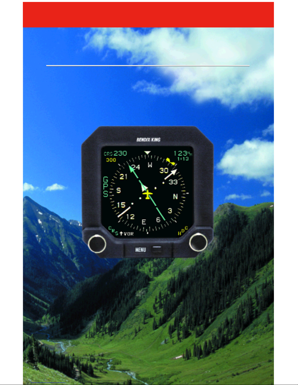
KI 825
Pilot’s Guide
Pilot’s Guide
Safety Display System
Safety Display System
Electronic Horizontal Situation Indicator
Electronic Horizontal Situation Indicator
For Units Having “-2”, “-3” and “-4” Softwa r e
KI 825
Bendix/King
Bendix/King
®
®

W A R N I N G
The enclosed technical data is eligible for export under Licanse Designation NLR
and is to be used solely by the individual/organization to whom it is addressed.
Diversion contrary to U.S. law is prohibited.
COPYRIGHT NOTICE
Copyright ©2002, 2004, 2008 Honeywell International Inc. All rights
r e s e r v e d .
Reproduction of this publication or any portion thereof by any means without the
express written permission of Honeywell International Inc. is prohibited. For further information contact the Manager, Technical Publications; Honeywell; One
Technology Center; 23500 West 105th St reet; Olathe, Kansas 66061.
Telephone: (913) 712-0400.


KI 825 Pilot’s Guide
006-18280-0000 (April 2008)
For Units Having Software Version 80-5205-X-4
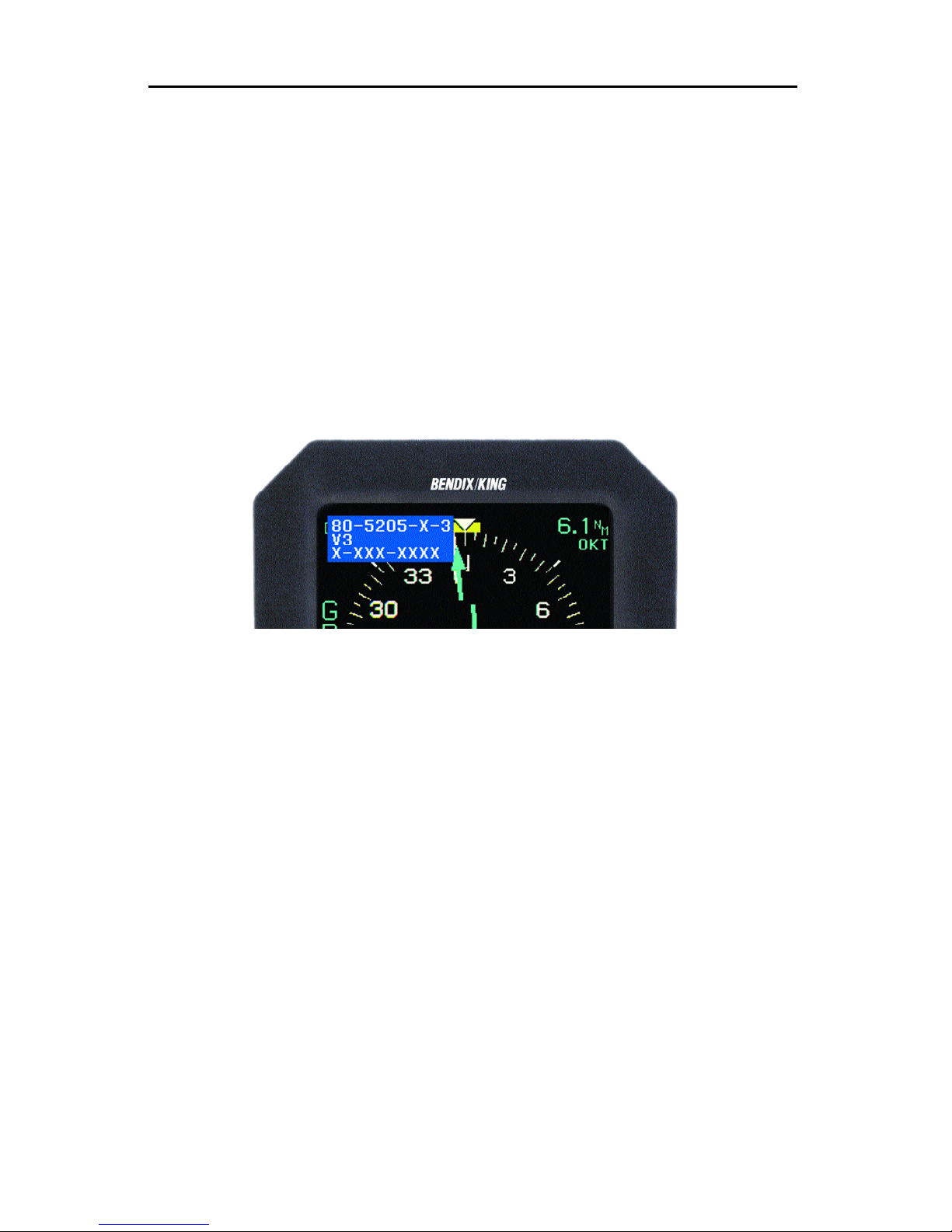
The software version number is displayed in the upper left corner of the
KI 825 display for several seconds when it is first turned on after a “cold
start”. In the figure below the software version is 80-5205-X-3. For this version it will read 80-5205-X-4.
Note: The KI 825 performs a cold start only when power has been off for
five minutes or longer. If the software version number is not displayed
when power is applied to the unit, turn power off for at least five minutes
before reapplying power.
In this Pilot’s Guide the operational description is applicable to all software
versions unless
“Software Version -2 Only”, “Software Version -3 Only”
or
“Software Version -4 Only ”
is specifically indicated in the text.
Operational characteristics of software version 80-5205-X-4, is similar to
80-5205-X-3 but have the following enhancements:
1 . VNAV or vertical deviation is provided when the selected navigational
source is a GPS and it is in approach phase.
1

2
I
Operational characteristics of software version 80-5205-X-3 are similar to
80-5205-X-2 but have the following enhancements:
1 . Allows for the option of separate day and night display dimming
ranges controlled by an external day/night switch. See section 2.5.
2 . Requires the user to press the MENU button in order to change the
displayed navigation sensor and to utilize the memory load function.
See sections 2.2, 2.3, 2.7, and 2.13.
3 . Allows for the option of an external switch to be utilized in changing
between GPS and VOR in addition to the existing method of navigation sensor selection from the KI 825 menu. See section 2.14.
4 . Removes the “CLR” option prompt on the right side of the MENU
when clearing lightning strikes from the 360 Map and Arc Map displays.
Note, there is no operational change to this feature. This
change was made to improve consistency in the use of options
p r o m p t s .
See section 2.4.
5 . Provides for more optimized installation interfaces with units like the
Garmin GNS 430/530 such that GPS/VLOC switching can now be
accomplished from both the GNS 430/530 and from the KI 825. This
includes the capability of having the GNS 430/530 change the KI 825
displayed navigation sensor during an automatic GPS to ILS transition. See sections 2.15 and 2.16.
6 . Allows for an installation option to not utilize the KI 825’s standard
course storage feature. This provides more efficient operation when
utilizing the automatic GPS to ILS switching capability offered by units
such as the Garmin GNS 430/530. See section 1.1.4.

3
5. Provides for more optimized installation interfaces with units like the
Garmin GNS 430/530 such that GPS/VLOC switching can now be
accomplished from both the GNS 430/530 and from the KI 825. This
includes the capability of having the GNS 430/530 change the KI 825
displayed navigation sensor during an automatic GPS to ILS transition. See sections 2.15 and 2.16.
6. Allows for an installation option to not utilize the KI 825’s standard
course storage feature. This provides more efficient operation when
utilizing the automatic GPS to ILS switching capability offered by units
such as the Garmin GNS 430/530. See section 1.1.4.

KI 825 Pilot’s Guide Table of Contents
TOC-1
LIST OF FIGURES
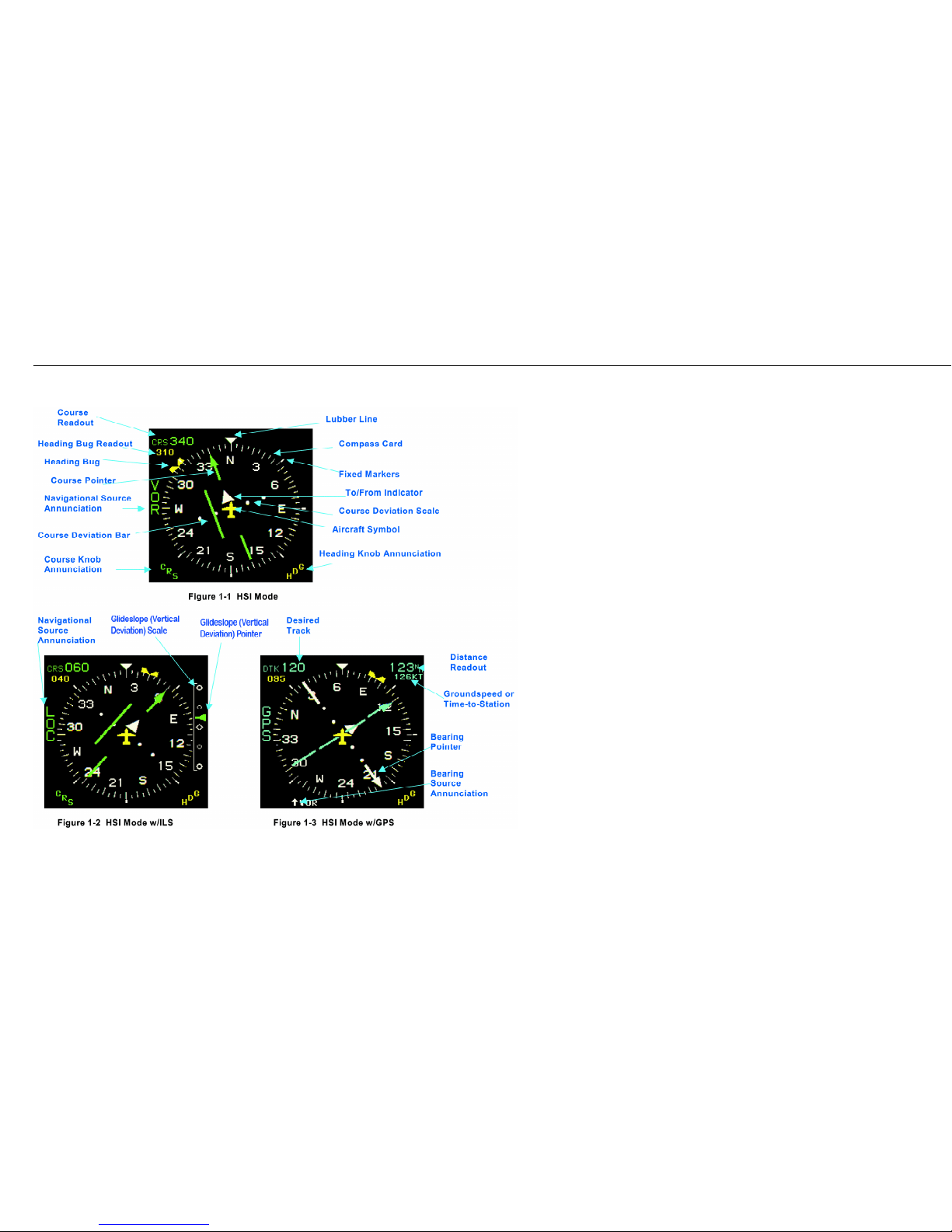
Figure 1-1 HSI Mode . . . . . . . . . . . . . . . . . . . . . . . . . . . . . . . . . .1-2
Figure 1-2 HSI Mode w/ILS . . . . . . . . . . . . . . . . . . . . . . . . . . . . .1-2
Figure 1-3 HSI Mode w/GPS . . . . . . . . . . . . . . . . . . . . . . . . . . . .1-2
Figure 1-4 360 Map Mode . . . . . . . . . . . . . . . . . . . . . . . . . . . . .1-10
Figure 1-5 360 Map Mode w/ILS . . . . . . . . . . . . . . . . . . . . . . . .1-10
Figure 1-6 360 Map Mode w/GPS . . . . . . . . . . . . . . . . . . . . . . .1-10
Figure 1-7 Helicopter Symbol . . . . . . . . . . . . . . . . . . . . . . . . . .1-12
Figure 1-8 Arc Map Mode . . . . . . . . . . . . . . . . . . . . . . . . . . . . .1-18
Figure 1-9 Arc Map Mode w/ILS . . . . . . . . . . . . . . . . . . . . . . . .1-18
Figure 1-10 Arc Map Mode w/GPS . . . . . . . . . . . . . . . . . . . . . . .1-18
Figure 1-11 Small Lightning Symbols . . . . . . . . . . . . . . . . . . . . .1-22
Figure 1-12 Medium Lightning Symbols . . . . . . . . . . . . . . . . . . .1-22
Figure 1-13 Large Lightning Symbols . . . . . . . . . . . . . . . . . . . . .1-22
Figure 2-1 Operating Controls . . . . . . . . . . . . . . . . . . . . . . . . . . .2-2
Figure 2-2 Menu Mode . . . . . . . . . . . . . . . . . . . . . . . . . . . . . . . .2-6
Figure 3-1 HSI Mode w/Error Flags . . . . . . . . . . . . . . . . . . . . . . .3-2
Figure 3-2 360 Map Mode w/Error Flags . . . . . . . . . . . . . . . . . . .3-2
TABLE OF CONTENTS
INTRODUCTION . . . . . . . . . . . . . . . . . . . . . . . . . . . . . . . . . . . . . . . . .i
1. DISPLAY BASICS . . . . . . . . . . . . . . . . . . . . . . . . . . . . . . . . . . . .1-3
1.1 HSI Mode . . . . . . . . . . . . . . . . . . . . . . . . . . . . . . . . . . . . . . . . . .1-3
1.1.1 Compass Card . . . . . . . . . . . . . . . . . . . . . . . . . . . . . . . . . . . .1-3
1.1.2 Aircraft Symbol . . . . . . . . . . . . . . . . . . . . . . . . . . . . . . . . . . . .1-4
1.1.3 Lubber Line . . . . . . . . . . . . . . . . . . . . . . . . . . . . . . . . . . . . . . .1-4
1.1.4 Primary Navigational Source Annunciation . . . . . . . . . . . . . .1-4
1.1.5 Selected Heading . . . . . . . . . . . . . . . . . . . . . . . . . . . . . . . . . .1-5
1.1.6 Course Pointer . . . . . . . . . . . . . . . . . . . . . . . . . . . . . . . . . . . .1-5
1.1.7 Course Readout . . . . . . . . . . . . . . . . . . . . . . . . . . . . . . . . . . .1-5
1.1.8 Course Deviation Display . . . . . . . . . . . . . . . . . . . . . . . . . . . .1-6
1.1.9 Bearing Pointer . . . . . . . . . . . . . . . . . . . . . . . . . . . . . . . . . . . .1-6
1.1.10 Bearing Source Annunciation . . . . . . . . . . . . . . . . . . . . . . . .1-6
1.1.11 Distance Readout to Selected NAV Source Waypoint . . . . .1-6
1.1.12 Distance Readout to Selected Bearing Source Waypoint . . .1-7
1.1.13 TO/FROM Display . . . . . . . . . . . . . . . . . . . . . . . . . . . . . . . .1-7
1.1.14 Glideslope (Vertical Deviation) Display . . . . . . . . . . . . . . . .1-7
1.1.15 Groundspeed Readout . . . . . . . . . . . . . . . . . . . . . . . . . . . . .1-7
1.1.16 Time-to-Station Readout . . . . . . . . . . . . . . . . . . . . . . . . . . .1-7

Table of Contents
KI 825 Pilot’s Guide
TOC-2
1.2 360 Map Mode . . . . . . . . . . . . . . . . . . . . . . . . . . . . . . . . . . . . .1-13
1.2.1 Map Mode Selected Course . . . . . . . . . . . . . . . . . . . . . . . . .1-13
1.2.2 360 Map Course Deviation Indicator . . . . . . . . . . . . . . . . . .1-13
1.2.3 TO/FROM Display . . . . . . . . . . . . . . . . . . . . . . . . . . . . . . . .1-13
1.2.4 Moving Map Symbology . . . . . . . . . . . . . . . . . . . . . . . . . . . .1-14
1.3 Arc Map Mode . . . . . . . . . . . . . . . . . . . . . . . . . . . . . . . . . . . . .1-19
1.4 Lightning Display Overlay . . . . . . . . . . . . . . . . . . . . . . . . . . . .1-23
1.4.1 Display Symbols . . . . . . . . . . . . . . . . . . . . . . . . . . . . . . . . . .1-23
1.4.2 Lightning Annunciation . . . . . . . . . . . . . . . . . . . . . . . . . . . . .1-23
2. BUTTONS, KNOBS, AND MENU OPTIONS . . . . . . . . . . . . . . .2-3
2.1 Auto Heading Bug Synchronization . . . . . . . . . . . . . . . . . . . . . .2-3
2.2 Menu Mode Operations . . . . . . . . . . . . . . . . . . . . . . . . . . . . . . .2-3
2.3 Menu Dynamics . . . . . . . . . . . . . . . . . . . . . . . . . . . . . . . . . . . . .2-7
2.4 Menu Items . . . . . . . . . . . . . . . . . . . . . . . . . . . . . . . . . . . . . . . .2-8
2.5 Display Brightness (BRITE) . . . . . . . . . . . . . . . . . . . . . . . . . .2-10
2.6 Range (RNG) . . . . . . . . . . . . . . . . . . . . . . . . . . . . . . . . . . . . .2-10
2.7 Navigation Source (NAV) . . . . . . . . . . . . . . . . . . . . . . . . . . . .2-10
2.8 Display Mode (MODE) . . . . . . . . . . . . . . . . . . . . . . . . . . . . . .2-11
2.9 Bearing Pointer Source (BRG) . . . . . . . . . . . . . . . . . . . . . . . .2-11
2.10 Lightning Overlay (LGHTN) . . . . . . . . . . . . . . . . . . . . . . . . .2-11
2.11 Clear Lightning Strikes (CLR) . . . . . . . . . . . . . . . . . . . . . . . .2-12
2.12 Memory Functions (MEMRY) . . . . . . . . . . . . . . . . . . . . . . . .2-12
2.13 Groundspeed or Time-To-Station (GSTTS) . . . . . . . . . . . . .2-13
2.14
(Software Versions -3 and -4 Only)
Optional Navigation Source
Select Switch . . . . . . . . . . . . . . . . . . . . . . . . . . . . . . . . . . . . .2-13
2.15
(Software Versions -3 and -4 Only)
Operational Characteristics
of Single KI 825 with Dual GNS 430 (or 530) Installation . . . .2-13
2.16
(Software Versions -3 and -4 Only)
Operational Characteristics
of Dual KI 825 with Dual GNS 430 (or 530) Installation . . . . .2-14
3. ERROR FLAGS AND WARNINGS . . . . . . . . . . . . . . . . . . . . . . .3-3
APPENDIX A DEFINITIONS AND ABBREVIATIONS . . . . . . . . . .A-1

KI 825 Pilot’s Guide Introduction
i
INTRODUCTION
The KI 825 combines critical flight information in an easy-to-use, high-resolution presentation. At the touch of a button, a pilot can configure the
presentation to display only what’s required for the phase of flight. It contains all of the hardware and software functions necessary to display
information to the pilot concerning the operation of a Horizontal Situation
Indicator (HSI) or Navigation Map Display.
The KI 825 combines the display functions of the standard Directional
Gyro with VOR/LOC course deviation indication, glideslope/vertical deviation (Vertical VNAV deviation is only available with Software version 4),
and bearing.
When interfaced to a GPS system, the KI 825 will display a GPS flight
path with waypoint indications. When interfaced to a lightning detection
system, it will provide the pilot information concerning storm activity.
Due to different aircraft system configurations, such as number of or type
of interfaces for the NAV or GPS systems or presence of lightning systems, some features or capabilities of the EHSI may not be available for a
particular aircraft installation.
This Pilot’s Guide will introduce you to the KI 825 and walk you through
the step-by-step operation of its many features. This guide assumes you
have basic operating knowledge of a Horizontal Situation Indicator and
explains how you can make full use of the KI 825 Safety Display System
in place of an electromechanical HSI.
More importantly, the KI 825 is a flight instrument intended to help minimize pilot workload, reduce cross cockpit scanning, and increase
situational awareness. Even with the KI 825’s substantial capabilities,
don’t forget to exercise good basic piloting techniques in responsibly and
safely flying your aircraft.

Introduction KI 825 Pilot’s Guide
ii
This page left blank intentionally

KI 825 Pilot’s Guide Chapter 1 Display Basics
1-1
This page left blank intentionally.
Chapter 1 Display Basics
1-2

1. DISPLAY BASICS
The KI 825, with pilot control, can be operated in any one of three modes:
HSI mode, 360 Map mode, and Arc Map mode.
In HSI mode, the KI 825 displays navigational information in the standard
360-degree compass format. The display contains information such as
compass card, navigational source indicator, heading bug, bearing pointer,
course arrow with course deviation indicator, course readout, TO/FROM
indicator, groundspeed and time-to-station, glideslope indicator (vertical
deviation), and error flags. While in HSI mode, the moving map and lightning overlays are not available.
In 360 Map mode, the KI 825 displays navigational information in a 360degree compass format. The same navigational information that is
available in HSI mode is displayed except there is no course arrow and
the CDI is moved to the bottom of the display. In addition, the KI 825 can
display GPS moving map information, including flight plan and direct to
waypoints, course lines, and map scale. The lightning overlay may also be
displayed while in this mode.
In Arc Map mode, the KI 825 displays the same information as it does in
the 360 Map mode but the display only shows approximately 45 degrees
each side of aircraft heading.
1.1 HSI MODE
This section describes the contents of the HSI mode and the elements
common to 360 Map and Arc Map modes. The HSI mode is an electronic
representation of a standard electromechanical HSI. While in HSI mode,
the moving map and lightning overlays are not available. Figures 1-1 to 13 are on a foldout page for reference as the section is being reviewed.
1.1.1 COMPASS CARD
A 360-degree rotating compass card indicates aircraft heading. The heading is shown with respect to magnetic north. A fixed yellow symbolic
aircraft in the center of the compass card indicates the aircraft’s relationship to the horizontal situation display. The compass card is divided into
5-degree increments with the 10-degree divisions being longer to help with
identification of the current heading. Fixed 45-degree markers are positioned around the outside of the compass card.
KI 825 Pilot’s Guide Chapter 1 Display Basics
1-3

1.1.2 AIRCRAFT SYMBOL
The EHSI contains a fixed aircraft symbol at the center of the display. This
symbol is for positional reference and serves the same purpose as those
contained on mechanical HSI units. This symbol may be configured for
fixed-wing aircraft or rotorcraft during installation.
1.1.3 LUBBER LINE
This line represents a heading reference index. This line is an extension of
the nose of the fixed aircraft symbol and does not move.
1.1.4 PRIMARY NAVIGATIONAL SOURCE ANNUNCIATION
The navigation source selected by the pilot is annunciated vertically on the
left side of the display next to the compass card.
Two types of navigation sources are possible: VOR and GPS. When the
selected navigational source is a VOR and a localizer frequency is tuned,
the VOR annunciation will be changed to a LOC annunciation. Up to two
of each type of navigational sources can be annunciated.
The color of the navigational source annunciation will be cyan for GPS
(when not in approach phase) and green for GPS (when in approach
phase) and for VOR.
The last course setting (before a navigational source change) is stored in
the indicator and recalled when the navigational source is reselected.
(e.g., VOR is the selected navigational source with the course set at 300°.
The navigational source is changed to GPS and the course changes to
240°. When VOR is reselected as the navigational source, the course
returns to 300° automatically). The EHSI does not differentiate between
VOR1 and VOR2 or GPS1 and GPS2 when storing course settings.
(Software Versions –3 and -4 Only)
The course storage feature described
in the previous paragraph may be disabled at the time of KI 825 installation if the feature is not desired. The most common reason to have this
feature disabled is to optimize the automatic GPS to ILS switching capability provided by units such as the Garmin GNS 430/530. When disabled,
the course pointer doesn’t change position when switching between GPS
and ILS navigation sensors.
Note 1: The EHSI’s ability to annunciate navigational source numerals
(e.g., VOR 1, VOR 2, GPS 1, GPS 2) is dependent on the number and
type of each navigational source as well as the method used to interface
the navigational sources to the KI 825.
Chapter 1 Display Basics KI 825 Pilot’s Guide
1-4

Note 2: The EHSI may not display a primary navigational source annunciation if the aircraft is configured to utilize external relay switching instead
of utilizing the KI 825’s internal switching.
1.1.5 SELECTED HEADING
A notched heading bug (amber) is manually rotated around the compass
card by the heading set knob. The heading bug indicates selected heading, and once set, rotates with the compass card. A clockwise (CW)
rotation of the knob produces clockwise (CW) rotation of the heading bug
and vice versa. The knob response will be dependent on the speed of
rotation. A heading control annunciator is displayed next to the knob. A
three-digit numeric heading readout is an indication of the position of the
heading bug and is located on the top left corner of the display just below
the course readout.
1.1.6 COURSE POINTER
When the primary navigational source is a VOR, the selected course
pointer is manually rotated around the compass card by the course set
knob. The pointer indicates the desired navigation course. The color of the
course pointer matches the color of the primary navigational source
annunciation.
When the primary navigational source is a GPS operating in the LEG
mode, the course pointer is replaced with a desired track (DTK) and the
course set knob is not active.
When the primary navigational source is a GPS operating in OBS mode,
the course set knob is used to select the desired OBS course. A clockwise
(CW) rotation of the course set knob produces CW rotation of the course
pointer and vice versa. A course control annunciator is displayed next to
the knob.
1.1.7 COURSE READOUT
The course readout is depicted by a three-digit numeric display located in
the upper left corner of the display and is proceeded by CRS (DTK if
source of data is a GPS that is in LEG mode). The color of this display is
the same as the selected course pointer.
KI 825 Pilot’s Guide Chapter 1 Display Basics
1-5

1.1.8 COURSE DEVIATION DISPLAY
The course deviation scale (two white dots on each side of the aircraft
symbol) provides a reference for the course deviation bar. The course
deviation bar is the center bar of the course pointer. The course deviation
bar indicates the centerline of the selected navigation course or localizer
course in relation to the aircraft. The course deviation scale and pointer
rotate with the compass card when set.
In the event of a NAV system failure, the deviation bar is removed.
1.1.9 BEARING POINTER
The bearing pointer is represented by a white, single-bar, disconnected
arrowhead and tail located at the edge of the compass card. The bearing
pointer indicates the relative bearing to the selected bearing source. If the
bearing source is a VOR and a ILS/LOC frequency is tuned, the bearing
pointer is removed from the display.
If a valid NAV signal is not being received, the bearing pointer is removed
from the display.
1.1.10 BEARING SOURCE ANNUNCIATION
The bearing source selected by the pilot is annunciated in the lower left
corner of the display proceeded by a small arrow icon. Two types of navigation sources are possible: VOR or GPS. Up to two of each system can
be annunciated (e.g., VOR 1, VOR 2) depending on the interface.
The color of the annunciation will be the same as the bearing pointer.
If the bearing source is a VOR and an ILS/LOC frequency has been tuned,
the bearing pointer will be removed.
Note: The bearing pointer source annunciation will only show numerals
(e.g., VOR 1, VOR 2, GPS 1, GPS 2) if there is more than one VOR or
more than one GPS interfaced as bearing pointers.
1.1.11 DISTANCE READOUT TO SELECTED NAV SOURCE
WAYPOINT
When GPS is the selected NAV source, GPS distance is displayed in the
upper right corner of the indicator. A range flag consisting of four dashes
replaces the numeric display, whenever the distance reading is invalid.
The range of the display will be 0.0 to 9999. Tenths of nautical miles are
shown whenever the distance is less than 100 nautical miles. DME distance is not displayed.
Chapter 1 Display Basics KI 825 Pilot’s Guide
1-6

KI 825 Pilot’s Guide Chapter 1 Display Basics
1-7
1.1.12 DISTANCE READOUT TO SELECTED BEARING SOURCE
WAYPOINT
When GPS is the selected navigational source for the bearing pointer, distance is displayed in the lower right corner of the indicator. A range flag
consisting of four dashes replaces the numeric whenever the distance
reading is invalid. The range of the display will be 0.0 to 9999. Tenths of
nautical miles will be shown whenever the distance is less than 100 nautical miles. DME distance is not displayed.
1.1.13 TO/FROM DISPLAY
The TO/FROM indicator is a white triangle, located inline with the course
pointer. If the navigation signal presented to the EHSI is not valid,
TO/FROM symbol will be removed from the display.
1.1.14 GLIDESLOPE (VERTICAL DEVIATION) DISPLAY
A white, stationary, vertical scale located on the right side of the indicator
is the reference for the glideslope/vertical deviation pointer.The pointer is
arrowhead shaped, and the color matches the NAV source annunciator.
The glideslope (vertical deviation) scale is visible when an ILS/LOC frequency is selected or when the selected navigational source is a GPS and
it is in approach phase. (Vertical VNAV deviation is only available with
Software version 4)
1.1.15 GROUNDSPEED READOUT
The groundspeed readout may be displayed if a GPS is selected as the
primary navigational source. The groundspeed readout is located in the
upper right corner beneath the distance indicator followed by the suffix
“KT” for knots. The range of the display will be from 0 to 999. A groundspeed error flag consisting of dashes will replace the numeric display
whenever the groundspeed is invalid. Either groundspeed or time-to-station may be displayed in this location.
1.1.16 TIME-TO-STATION READOUT
The time-to-station readout may be displayed if GPS is selected as the
primary navigation source. Time-to-station (TTS) readout is a numeric display located in the upper right corner beneath the distance indicator.
The range of the display for the hours and minutes will be from 0:00 to
9:59. For times greater than 9:59, the time field will be blank. A TTS error
flag consisting of yellow dashes and a colon replaces the numeric display
whenever the time-to-station is invalid. Either time-to-station or the
groundspeed may be displayed in this location.
 Loading...