

Page 1
Pilot’s Guide
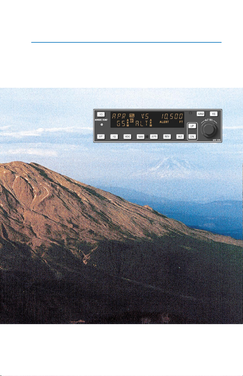
KFC 225
Bendix/King
Automatic Flight Control System
®
006-18035-0000
September 2004
N
Page 2

WARNING
The enclosed technical data is eligible for export under Licanse Designation
NLR and is to be used solely by the individual/organization to whom it is
addressed. Diversion contrary to U.S. law is prohibited.
COPYRIGHT NOTICE
Copyright ©1999, 2004 Honeywell International Inc.
All rights reserved.
Reproduction of this publication or any portion thereof by any means without
the express written permission of Honeywell International Inc. is prohibited.
For further information contact the Manager, Technical Publications;
Honeywell; One Technology Center; 23500 West 105th Street; Olathe,
Kansas 66061. Telephone: (913) 712-0400.
Page 3

Revision History and Instructions
Manual KFC 225 AFCS Pilot’s Guide
Revision 1, September 2004
Part Number 006-18035-0000
This revision incorporates a note further explaining the Altitude Hold
function.
The following pages were changed:
Front Cover, Copyright, 9, 13, Back Cover
R-1
Page 4

Revision History and Instructions
Manual KFC 225 AFCS Pilot’s Guide
Revision 0, April 1999
Part Number 006-18035-0000
This is the original version of this publication.
R-2
Page 5

Table of Contents
Introduction . . . . . . . . . . . . . . . . . . . . . . . . . . . . . . . . . . . . . . . . . . . . . . . . . . . . .1
General Description . . . . . . . . . . . . . . . . . . . . . . . . . . . . . . . . . . . . . . . . . . . . .2
System Integration . . . . . . . . . . . . . . . . . . . . . . . . . . . . . . . . . . . . . . . . . . . . . .2
Power Application and Preflight Tests . . . . . . . . . . . . . . . . . . . . . . . . . . . . . .4
KFC 225 System Operation . . . . . . . . . . . . . . . . . . . . . . . . . . . . . . . . . . . . . . . .5
Controls and Displays Operation . . . . . . . . . . . . . . . . . . . . . . . . . . . . . . . . . . .5
Altitude Alerting and Preselect . . . . . . . . . . . . . . . . . . . . . . . . . . . . . . . . . . . .10
Altitude Alerter . . . . . . . . . . . . . . . . . . . . . . . . . . . . . . . . . . . . . . . . . . . . . . .10
Altitude Preselect . . . . . . . . . . . . . . . . . . . . . . . . . . . . . . . . . . . . . . . . . . . .10
Voice Messaging . . . . . . . . . . . . . . . . . . . . . . . . . . . . . . . . . . . . . . . . . . . . . .11
System Operating Modes . . . . . . . . . . . . . . . . . . . . . . . . . . . . . . . . . . . . . . . .12
Pitch and Roll Attitude Hold (PIT) Modes . . . . . . . . . . . . . . . . . . . . . . . . .12
Altitude Hold (ALT) Mode . . . . . . . . . . . . . . . . . . . . . . . . . . . . . . . . . . . . . .13
KFC 225 Detailed System Operation . . . . . . . . . . . . . . . . . . . . . . . . . . . . . . .14
Takeoff And Climb To Assigned Altitude . . . . . . . . . . . . . . . . . . . . . . . . . . .14
GPS Capture . . . . . . . . . . . . . . . . . . . . . . . . . . . . . . . . . . . . . . . . . . . . . . . .16
Outbound On Front Course For Procedure Turn To ILS Approach . . . . . .18
Front Course ILS Approach . . . . . . . . . . . . . . . . . . . . . . . . . . . . . . . . . . . .20
Outbound on GPS Approach . . . . . . . . . . . . . . . . . . . . . . . . . . . . . . . . . . . .22
Inbound on GPS Approach . . . . . . . . . . . . . . . . . . . . . . . . . . . . . . . . . . . . .24
KCS 55A Compass System . . . . . . . . . . . . . . . . . . . . . . . . . . . . . . . . . . . . . . .27
KI 525A Indicator . . . . . . . . . . . . . . . . . . . . . . . . . . . . . . . . . . . . . . . . . . . . . .28
Description of Indicator and Display Functions . . . . . . . . . . . . . . . . . . . . . . .28
Slaving Meter (KA 51B) . . . . . . . . . . . . . . . . . . . . . . . . . . . . . . . . . . . . . . . . .30
KMT 112 Magnetic Slaving Transmitter . . . . . . . . . . . . . . . . . . . . . . . . . . . . .31
KG 102A Directional Gyro . . . . . . . . . . . . . . . . . . . . . . . . . . . . . . . . . . . . . . .31
Abnormal Circumstances . . . . . . . . . . . . . . . . . . . . . . . . . . . . . . . . . . . . . . . .33
Flight Procedures with the KCS 55A . . . . . . . . . . . . . . . . . . . . . . . . . . . . . . .34
General Emergency Procedures . . . . . . . . . . . . . . . . . . . . . . . . . . . . . . . . . . .41
Autopilot Malfunction . . . . . . . . . . . . . . . . . . . . . . . . . . . . . . . . . . . . . . . . . . .41
Rev. 0
Apr/99
KFC 225 AUTOMATIC FLIGHT CONTROL SYSTEM
i
Page 6

Table of Contents
This page intentionally left blank
ii
KFC 225 AUTOMATIC FLIGHT CONTROL SYSTEM
Rev. 0
Apr/99
Page 7

Introduction
Introduction
The pressures of single-pilot instrument flying place critical demands on
the skill and concentration of any
pilot. To aid you in meeting these
challenges, Honeywell has developed the KFC 225 Flight Control
System. This system places recent
flight control advances normally
found only in high end ‘jet’ autopilots
into the cockpits of General Aviation
Aircraft.
The heart of the system is a
lightweight, integrated autopilot computer combining the functions of
computer, mode selector, altitude
pre-selector, and the optional yaw
damper into one unit. The system
has been designed to work with
your Bendix/King equipment from
day one. It can interface directly with
your EFIS system, take roll steering
commands from your KLN 90B IFR
GPS, and, when available, listen to
your KRA 10A radar altimeter to
improve approach tracking.
It is significant that this Silver Crown
Plus flight control system has been
designed from the beginning to interface with your Silver Crown Plus
package of avionics. Consider the
advantage of having your avionics
working together as an integrated
system rather than as a group of
unrelated components built by several different manufacturers.
To fully utilize the impressive capabilities of this full-featured system it
is important that the pilot understand
the capabilities and limitations of the
system. The pilot should take time
to read and thoroughly understand
the FLIGHT MANUAL SUPPLEMENT for the autopilot installation
specific to his aircraft. This Pilot’s
Guide should be used to gain additional insight into the operation of the
system through the specific operating scenarios. The FLIGHT MANUAL SUPPLEMENT information
shall always take precedence over
the information found in this manual.
Rev. 0
Apr/99
KFC 225 AUTOMATIC FLIGHT CONTROL SYSTEM
1
Page 8
Introduction
20
10
102010
20
20
10
General Description
The KFC 225 Three Axis system provides lateral, vertical and optional yaw
modes with altitude preselect.
AIR
DH
AIR
ı
NAV HDG
E
12
6
GS GS
3
N
33
30
ı
15
S
21
24
W
VS
YD
G
P R
AP
HDG
FD
APR REV
NAV
ARM
S
E
T
L
L
A
UP
ALT
DN
KFC 225
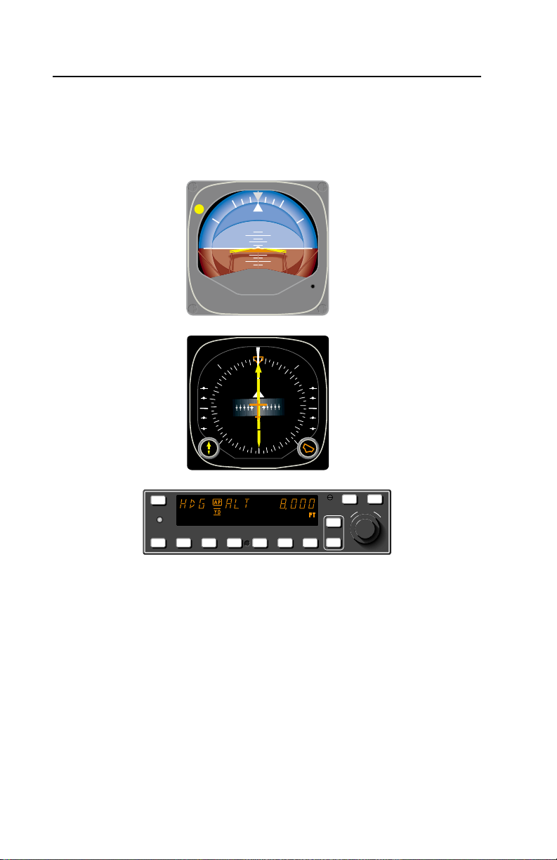
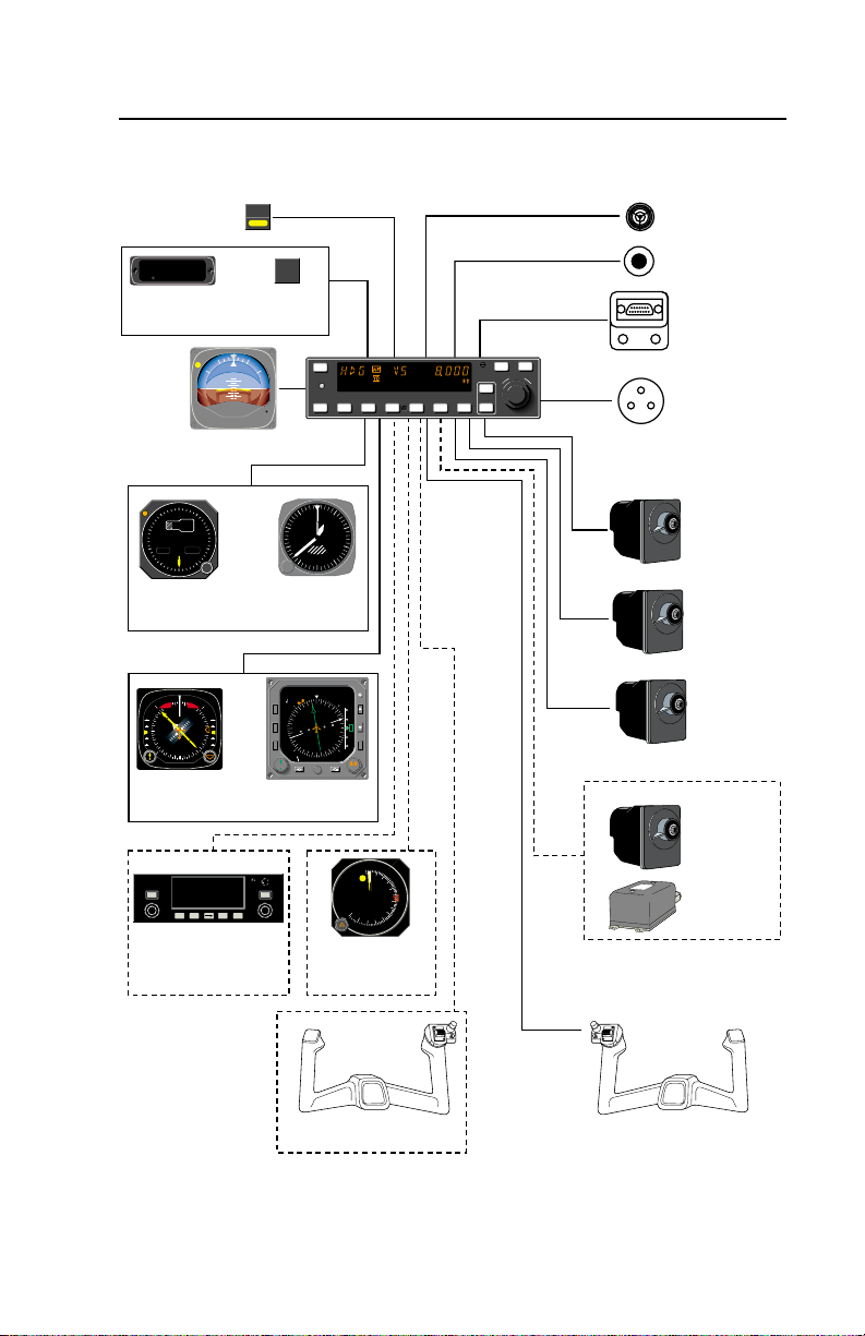
System Integration
The system diagram on the next page shows the components and their relationship in a typical KFC 225 system. The actual components on individual
systems may vary slightly depending on certification and installation requirements.
The system diagram reflects that the KFC 225 system controls pitch, roll and
yaw (optional) axes of the aircraft.
2
KFC 225 AUTOMATIC FLIGHT CONTROL SYSTEM
Rev. 0
Apr/99
Page 9
Introduction
20
20
10
10
102010
20
600
500
6
A/P Master Switch
AP
NAV
REV
ALT
VS
HDG
APR
GS
CAP
GA
YD
ARM
ARM
ALT
TRIM
KA 285
Remote Mode
Annunciator
DH
KI 256 Attitude Gyro
ALT
0
9
1
0,
2
8
ALT
MB IN HG
7
3
29.99
101
6
4
5
B
KEA 346
Servoed
Altimeter
NAV HDG
N
3
3
3
GS GS
6
0
3
E
W
1
2
4
2
1
5
1
2
S
ı
KCS 55A
Compass
System
B
KLN 90B TSO
NAV
CALC
FPL
STAT
MODE
SETUP
TRIP
OTHER
ALT
D
CLR ENT
MSG
Optional
ARINC 429
GPS Interface
OR
Annunciaor
AIR
AIR
ı
OR
OR
NAV
D/T
ACTV
REF
CTR
AP
TRIM
FAIL
Trim Fail
1
2
N
A
V
H
S
I
CRS
GPS
BRT
CRSRCRSR
APT
VOR
PULL
NDB
SCAN
INT
SUPL
YD
G
P R
AP
FD
0
1
9
8
2
ALT
3
7
ENCODING
4
6
5
KEA 130A
Encoding
Altimeter
CRS
4.
350
120 KT
5
12
N
3
3
3
6
0
3
L
O
E
W
C
1
1
4
2
2
1
5
1
2
S
ADF 2
BRT
EHI 40
EFIS
ALTITUDE
O
T
H
S
U
P
Optional KRA 10A
Radar Altimeter
HDG
TST
NM
REF
11.
5
G
S
A
R
C
330°
HDG
DH
RADAR
X 100 FEET
25
20
15
T
E
S
T
ıı
System
Audio Alert
Remote Terminal
I/F Connector
(AFCS Maint. Plug)
KCM 100
Configuration
Aircraft
Static
Port
Module
KS 271C
Roll Servo
KS 270C
Pitch Servo
KS 272C
Trim Servo
KC 225
Flight Computer
VS
ARM
S
E
T
L
L
A
APR REV
NAV
UP
ALT
DN
KFC 225
Optional Yaw Axis
KS 271C
Yaw Servo
OFF
50
1
2
3
4
5
10
2
3
3
G
R
K
RATE GYRO
ı
KRG 331
or
KRG 332
Rate Gyro
Optional Dual
Control Wheel Switches
Control Wheel Switches
KFC 225 System Diagram
Rev. 0
Apr/99
KFC 225 AUTOMATIC FLIGHT CONTROL SYSTEM
3
Page 10
Introduction
Power Application and Preflight Tests
YD
G
P R
AP
HDG
FD
KFC 225 Preflight Test
YD
G
P R
AP
HDG
FD
KFC 225 Preflight Test Complete
NAV
NAV
APR REV
APR REV
VS
ARM
S
E
T
L
L
A
UP
ALT
DN
UP
ALT
DN
ARM
KFC 225
VS
S
E
T
L
L
A
KFC 225
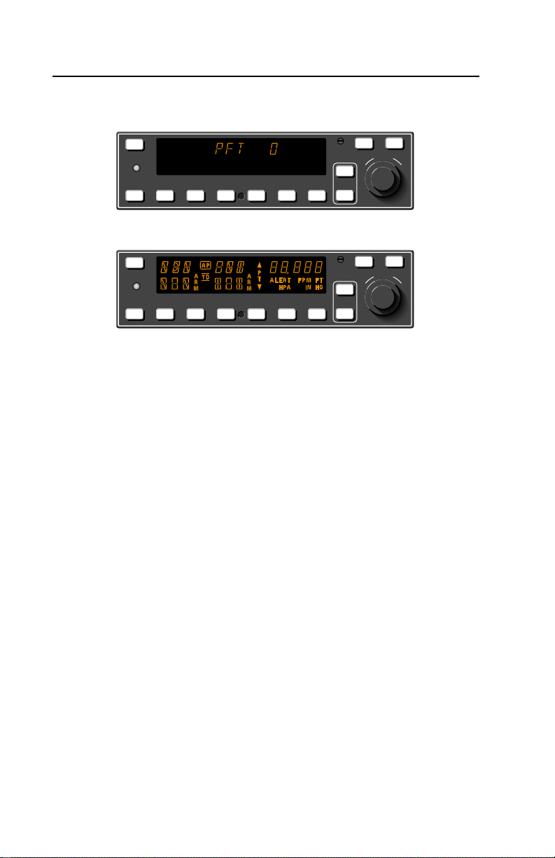
A preflight test is performed
upon power application to the computer. This test is a sequence of
internal checks that validate proper
system operation prior to allowing
autopilot engagement. The preflight
test (PFT) sequence is indicated by
“PFT” with an increasing number for
the sequence steps. Successful
completion of self test is identified by
all display segments being illuminated (Display Test), the Flight
Director command bars brought into
view and the disconnect tone sounding.
NOTE: Following the preflight test,
the red P warning on the face of the
autopilot may illuminate indicating
that the pitch axis cannot be
engaged. This condition should be
temporary, lasting no more than 30
seconds. The P will extinguish and
normal operation will be available.
4
KFC 225 AUTOMATIC FLIGHT CONTROL SYSTEM
Rev. 0
Apr/99
Page 11
KFC 225 System Operation
Controls and Displays Operation
System Operation
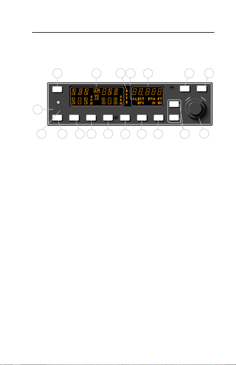
1617 15 1418
YD
G
P R
1
AP
2 4 10
3
HDG
FD
5 6 7 8 9
NAV
APR REV
ALT
Full KFC 225 Three-Axis with Altitude Preselect Display
1. PITCH AXIS, (P) ANNUNCIA-
TOR - When illuminated, indicates
failure of the pitch axis and will lead
to disengagement of the autopilot.
(Will also illuminate during short term
vertical accelerations in excess of
+1.6g or less than +0.4g which may
not cause autopilot disengagement.)
4. FLIGHT DIRECTOR (FD)
MODE SELECTOR BUTTON –
When pressed will engage the flight
director into the basic roll (ROL)
mode which functions as a wing leveler, and into the pitch attitude (PIT)
hold mode. The pitch attitude maintained will be the pitch attitude present at the moment of FD button
2. ROLL AXIS (R) ANNUNCIA-
TOR - When illuminated, indicates
failure of the roll axis and will disen-
press. When pressed again (and the
autopilot is not engaged) will disengage the flight director.
gage the autopilot.
5. HEADING (HDG) MODE
3. AUTOPILOT ENGAGE/DISEN-
GAGE (AP) BUTTON - When
pressed, engages the flight director,
autopilot and yaw damper (if
installed). If the flight director is not
already engaged, the system will
engage into the basic wings level
(ROL) and pitch (PIT) attitude hold
modes. The pitch attitude main-
tained will be the pitch attitude pre-
sent at the moment of AP button
press. When pressed again, will dis-
SELECTOR BUTTON - When
pressed, will engage the Heading
mode, which commands the airplane
to turn to and maintain the heading
selected by the heading bug on the
HSI. A new heading may be
selected at any time and will result in
the airplane turning to the new heading. Button can also be used to toggle between HDG and ROL modes.
This button will engage the flight
director.
engage the autopilot.
UP
DN
13 12
ARM
S
T
L
A
E
L
VS
KFC 225
11
Rev. 0
Apr/99
KFC 225 AUTOMATIC FLIGHT CONTROL SYSTEM
5
Page 12

System Operation
6. NAVIGATION (NAV) MODE
SELECTOR BUTTON - When
pressed, will arm the navigation
mode. If the selected navigation sensor is less than 50% deflected when
armed, the system will automatically
capture. Otherwise the capture point
will vary based on needle deflection
and closure rate. The mode provides
automatic beam capture and tracking of VOR, LOC or GPS as
selected for presentation on the HSI.
NAV mode is recommended for en
route navigation tracking. If pressed
when NAV mode is either armed or
coupled, will disengage the mode.
This button will engage the flight
director.
7. APPROACH (APR) MODE
SELECTOR BUTTON - When
pressed, will arm the Approach
mode. If the selected navigation sensor is less than 50% deflected when
armed, the system will automatically
capture. Otherwise the capture point
will vary based on needle deflection
and closure rate. This mode provides automatic beam capture and
tracking of VOR, GPS or LOC with
Glideslope (GS) on an ILS, as
selected for presentation on the HSI.
APR ARM will annunciate. If pressed
when APR mode is either armed or
coupled, will disengage the mode.
This button will engage the flight
director. (See the NOTE following
item 8).
8. BACK COURSE APPROACH
(REV) MODE SELECTOR BUTTON
– (not available when optional ED
461 EHSI installed). When pressed,
will select the back course approach
mode. If the selected navigation sen-
6
KFC 225 AUTOMATIC FLIGHT CONTROL SYSTEM
sor is less than 50% deflected when
armed, the system will automatically
capture. Otherwise the capture point
will vary based on needle deflection
and closure rate. This mode functions similarly to the approach mode
except that the autopilot response to
LOC signals is reversed and glideslope is inhibited. This button will
engage the flight director.
NOTE: If the optional ED 461
EHSI is installed, front and back
course selection is automatic and is
dependent upon the relative difference between the airplane heading
and the selected approach course. If
the airplane heading differs from the
selected course by greater than
105°, REV ARM will automatically
annunciate in anticipation of tracking
a localizer back course. If prior to
localizer capture the heading
changes (ie. during radar vectors or
a procedure turn) and falls within
105° of the selected course, APR
ARM will annunciate in anticipation
of tracking the localizer front course.
9. ALTITUDE HOLD (ALT) MODE
SELECT BUTTON - When
pressed, will engage the Altitude
Hold mode. The altitude maintained
is the altitude at the moment the ALT
button is pressed. If the ALT button
is pressed with an established climb
or descent rate present, there will be
approximately a 10% (of VS rate)
overshoot, with the airplane returned
positively to the selected altitude. If
pressed when ALT hold mode is
engaged, will disengage the mode,
defaulting to PIT mode. This button
will engage the flight director.
Rev. 0
Apr/99
Page 13

System Operation
10. VERTICAL TRIM (UP/DN) BUT-
TONS - The response of these but-
tons is dependent upon the vertical
mode present when pressed. If PIT
mode is active, successive button
presses will move the pitch attitude
hold reference either up or down by
0.5° per press, or at the rate of 0.8°
per second if held continuously, syn-
chronizing the pitch attitude refer-
ence to the current pitch attitude
upon release. If VS mode is active,
the initial button press will bring up
the commanded vertical speed in the
display. Subsequent immediate but-
ton presses will increment the verti-
cal speed command either up or
down at the rate of 100 ft/min per
button press, or at the rate of
approximately 300 ft/min per second
if held continuously. If ALT mode is
active, successive button presses
will move the altitude hold reference
altitude either up or down by 20 feet
per press, or if held continuously will
command the airplane up or down at
the rate of 500 ft/min, synchronizing
the altitude hold reference to the
actual airplane altitude upon button
release. (Note that neither the pitch
attitude nor the altitude hold refer-
ence is displayed. The display will
continue to show the altitude alerter
reference.)
11. ROTARY KNOBS - Used to
set the altitude alerter/altitude prese-
lect reference altitude. Large (outer)
knob changes reference by 1000’s
of feet, and the small (inner) knob
changes reference by 100’s of feet.
When the flight director is engaged,
will automatically arm a preselect
altitude hold capture.
12. VERTICAL SPEED (VS) MODE
SELECTOR BUTTON – When
pressed will engage the vertical
speed hold mode. The vertical
speed maintained is the vertical
speed present at the moment the VS
button is pressed. The vertical speed
command reference will initially be
displayed in place of the altitude
alert annunciation, defaulting back in
3 seconds to the altitude alerter
value. Pressing either the UP or DN
button will again cause the vertical
speed command reference to be displayed while causing it to increase or
decrease. When the VS button is
pressed again, it will disengage the
vertical speed mode. This button will
engage the flight director.
13. ALTITUDE ARM (ARM) BUT-
TON - When pressed will toggle altitude arming on or off. When ALT
ARM is annunciated, the automatic
flight control system will capture the
altitude displayed in the Altitude
Alerter/Vertical Speed Display (provided the aircraft is climbing or
descending to the displayed altitude). ALT ARM mode is engaged
automatically whenever the selected
altitude is changed via the rotary
knobs. Note that the alerter functions
are independent of the arming process thus providing full time alerting,
even when the flight director is disengaged. This button will engage the
flight director.
Rev. 0
Apr/99
KFC 225 AUTOMATIC FLIGHT CONTROL SYSTEM
7
Page 14

System Operation
14. SELECTED ALTITUDE/VERTICAL SPEED DISPLAY - Normally
displays the selected altitude. The
display indicates the reference vertical speed in FPM for 3 seconds after
the CWS button or the UP or DN
button is pressed and the VS mode
is engaged.
15. ALTITUDE ALERT (ALERT)
ANNUNCIATION - Illuminates as a
solid alert in the region from 1000 to
200 feet from the selected altitude if
the airplane was previously outside
of this region. Flashes (1) for two
seconds the first time the airplane
crosses the selected altitude and (2)
flashes continuously in the 200 to
1000 feet region if the airplane was
previously inside of this region (i.e.
at the selected altitude). An aural
alert consisting of five short tones is
associated with the visual alerting.
This aural alert occurs 1,000 feet
before a selected altitude while
approaching it and 200 feet after
leaving a selected altitude.
16. PITCH TRIM (PT) ANNUNCIATION - A flashing PT with an
accompanying arrow head is an indication that the request for auto trim
has lasted longer than 16 seconds.
A solid PT without an arrowhead is
an indication of a pitch trim fault. A
trim runaway will generate the solid
PT annunciation, a remote TRIM
FAIL annunciation and a continuous
alert tone. Refer to the EMERGENCY PROCEDURES in the airplane Flight Manual Supplement for
proper response to a pitch trim fault.
17. PITCH AND ROLL MODE,
AUTOPILOT AND YAW DAMPER
ANNUNCIATIONS - Displays the
active flight director pitch modes
(PIT, VS, ALT ARM, ALT CAP, ALT,
GS ARM, GS, GA, and roll modes
(ROL, HDG, NAV ARM, NAV, APR
ARM, APR, REV ARM, REV).
Displays when the autopilot (AP)
and yaw damper (YD) are engaged.
Also displayed will be a flashing AP
annunciation (5 seconds) at each
autopilot disconnect accompanied
by an aural tone (for 2 seconds).
18. YAW DAMPER (YD) BUTTON
(optional) – When pressed will
engage or disengage the yaw
damper independent of autopilot
operation. (The yaw damper
engages automatically when the
autopilot is engaged; however, the
yaw damper may then be disengaged or reengaged as desired.)
19. AUTOPILOT DISCONNECT
(AP DISC/TRIM INTER) SWITCH
(not shown) - When pressed will
disengage the autopilot and yaw
damper if installed, and interrupt
electric trim power. (Located on the
left horn of the pilot’s control wheel.
The switch is red in color.) May also
disengage the flight director depending on how the system is configured.
20. MANUAL ELECTRIC TRIM
SWITCHES (not shown) - When
both switches are pressed in the
same direction, will activate pitch
trim in the selected direction. If only
one switch is moved, the trim system
8
KFC 225 AUTOMATIC FLIGHT CONTROL SYSTEM
Rev. 0
Apr/99
Page 15

System Operation
will not operate. If one switch fails or
is moved and held for 3 seconds, the
trim monitoring system will detect a
switch failure resulting in a PT
annunciation on the autopilot display
and the disabling of the electric trim
system. Use of manual electric trim
during autopilot operation will disen-
gage the autopilot. (Located on the
pilot’s control wheel.)
21. CONTROL WHEEL STEERING
(CWS) MODE BUTTON (not shown)
- When pressed and held, disen-
gages the pitch, roll, yaw, and pitch
trim clutches allowing the pilot to
maneuver the airplane by hand.
Pressing the CWS button will also
sync the automatic flight control sys-
tem PIT, ROL, ALT or VS com-
mands to the actual attitude, altitude
or vertical speed present at the time
the button is released. It is not rec-
ommended to use the CWS for alti-
tude changes greater than 400 ft.
ROL will maintain wings level if CWS
is released at less than 6° bank
angle. (Located on the left horn of
the pilot’s control wheel.)
attitude such as through the UP/DN
button or CWS, etc. will cancel GA
and revert to pitch altitude hold.
(Located on the engine throttle).
23. OMNI BEARING SELECT
KNOB - Selects the desired course
to be tracked by the autopilot
(Located on the HSI.)
24. HEADING SELECT KNOB Positions the heading bug on the
compass card (Located on the HSI.)
25. TRIM FAIL ANNUNCIATOR
(not shown) - Illuminates whenever
the automated preflight self-test
detects a pitch trim fault or a continuous monitoring system detects a
pitch trim fault in flight. (Located on
the instrument panel. The annunciator is red in color.) Refer to the
EMERGENCY PROCEDURES in
the airplane Flight Manual
Supplement for proper response to
a pitch trim fault.
22. GO AROUND (GA) MODE
BUTTON (not shown) – When
pressed will engage the flight direc-
tor in a pitch up attitude and wings
level (ROL mode). GA will disen-
gage the autopilot, and cancel all
armed modes including an armed
altitude preselect. Lateral modes
such as HDG or NAV ARM may
subsequently be added. The autopi-
lot may subsequently be engaged.
Modification to the commanded pitch
Rev. 1
Sep/04
KFC 225 AUTOMATIC FLIGHT CONTROL SYSTEM
9
Page 16

System Operation
Altitude Alerting and Preselect
The Altitude Preselect function allows capturing of a selected altitude and
transferring into altitude hold. Manual input of selected altitude is accomplished through the rotary knobs on the faceplate of the KFC 225.
The Altitude Alerting function will visually and aurally announce approaching,
acquiring and deviation from a selected altitude.
Altitude Alerter
The function of the Altitude Alerter is
independent of the autopilot.
1. ALTITUDE SELECT knob ROTATE until the selected altitude
is displayed.
YD
G
P R
AP
APR REV
HDG
NAV
FD
ARM
T
L
A
UP
ALT
DN
Note: The ALERT annunciation is
illuminated 1000 ft. prior to the
selected altitude, extinguishes 200 ft.
prior to the selected altitude and illuminates momentarily when the
selected altitude is reached. Once
the selected altitude is reached, a
flashing ALERT illumination signifies
that the 200 ft. “safe band” has been
exceeded and will remain illuminated until 1000 ft. from the selected
altitude. Associated with the visual
alerting is an aural alert (five short
tones) which occurs 1000 ft. from
the selected altitude upon approaching the altitude and 200 ft. from the
selected altitude on leaving the altitude.
YD
G
P R
AP
APR REV
HDG
NAV
FD
ARM
T
L
A
UP
ALT
DN
Altitude Preselect
1. ALTITUDE SELECT knob ROTATE until selected altitude is
displayed. ARM annunciation
occurs automatically upon altitude
selection when the flight director is
engaged.
VS
S
E
L
KFC 225
YD
G
P R
AP
APR REV
HDG
NAV
FD
2. Airplane - ESTABLISH selected
vertical speed to intercept the
selected altitude.
YD
G
P R
AP
HDG
FD
APR REV
NAV
3. Upon altitude capture, ALT
ARM will extinguish and ALT will
be annunciated.
Note: Glideslope coupling (but not
glideslope ARM) will preclude an
altitude capture on an ILS.
YD
G
P R
AP
VS
S
E
L
KFC 225
FD
APR REV
HDG
NAV
VS
ARM
S
E
T
L
L
A
UP
ALT
DN
KFC 225
VS
ARM
S
E
T
L
L
A
UP
ALT
DN
KFC 225
VS
ARM
S
E
T
L
L
A
UP
ALT
DN
KFC 225
10
KFC 225 AUTOMATIC FLIGHT CONTROL SYSTEM
Rev. 0
Apr/99
Page 17

Voice Messaging
The following standard voice mes-
sages will be annunciated as condi-
tions warrant:
1. “TRIM IN MOTION, TRIM IN
MOTION…” - Pitch trim running
for more than 5 seconds.
2. “CHECK PITCH TRIM” - An
out of trim condition has existed
for 16 seconds.
a. Airplane Control Wheel -
GRASP FIRMLY, press CWS
and check for an out of pitch trim
condition. Manually retrim as
required.
b. CWS button - RELEASE.
c. AUTOPILOT OPERATION -
CONTINUE if satisfied that the
out of trim condition was tempo-
rary. DISCONTINUE if evidence
indicates a failure of the auto trim
function.
The following optional voice mes-
sages will be annunciated if the sys-
tem is configured for voice messag-
ing:
System Operation
1. “ALTITUDE” - 1000 feet
before approaching selected altitude.
2. “LEAVING ALTITUDE” - 200
feet away, departing selected altitude.
3. “AUTOPILOT” - Autopilot has
disengaged, either through pilot
action or automatically.
Rev. 0
Apr/99
KFC 225 AUTOMATIC FLIGHT CONTROL SYSTEM
11
Page 18

System Operation
System Operating Modes
VS
YD
G
P R
AP
HDG
FD
APR REV
NAV
Pitch and Roll Attitude Hold (PIT) Modes
The Pitch Attitude Hold (PIT)
mode allows constant attitude climbs
and descents. The AP or FD button
engages PIT mode.
To operate in the PIT mode
(with autopilot currently disengaged):
1. FD button - Press. Note ROL
and PIT are displayed. Pressing
the AP button will engage the
autopilot in ROL and PIT modes.
2. UP or DN button - Select
desired climb or descent attitude.
Each button stroke will increment
the pitch attitude by 0.5°. Pushing
and holding the UP or DN button
will cause the aircraft to pitch at
0.8° per second. Releasing the
button will sync the attitude to the
present pitch attitude.
To initiate a climb or descent from
Altitude Hold (ALT) mode:
1. ALT button - Press. Note ALT
changes to PIT referencing the
present pitch attitude.
2. UP or DN button - Select
desired climb or descent attitude.
Each button stroke will increment
the pitch attitude by 0.5°.
ARM
S
E
T
L
L
A
UP
ALT
DN
KFC 225
The ROL mode engages in wings
level Roll Attitude Hold mode.
To change ROL Attitude Hold Mode:
1. Press CWS and bank the aircraft to the desired bank angle. If
the bank angle is less than 6°
when the CWS button is released,
the autopilot will hold wings level.
If the bank angle is greater then 6°
when the CWS is released, the
autopilot will hold the bank angle
up to the maximum allowed by the
autopilot for that aircraft.
VS
YD
G
P R
AP
HDG
FD
APR REV
NAV
ARM
S
E
T
L
L
A
UP
ALT
DN
KFC 225
Vertical Speed (VS) Mode
The Vertical Speed (VS) mode
allows vertical speed climbs and
descents. The VS button engages
vertical speed mode.
To operate in the VS mode (with
autopilot currently disengaged):
1. VS button - Press. Note ROL,
VS and current vertical speed is
displayed. Pressing the AP button
will engage the autopilot in ROL
and VS modes.
2. UP or DN button - Select
desired climb or descent rate.
Each button stroke will increment
the vertical speed commanded up
or down by 100 ft/min per button
press, or at the rate of approximately 300 ft/min per second if
held continuously.
12
KFC 225 AUTOMATIC FLIGHT CONTROL SYSTEM
Rev. 0
Apr/99
Page 19

System Operation
To initiate a climb or descent from
Altitude Hold (ALT) mode:
1. VS button - Press. Note ALT
changes to VS and current vertical
speed is displayed.
2. UP or DN button - Select
desired climb or descent rate.
Each button stroke will change the
vertical speed commanded up or
down by 100 ft/min per button
press, or at the rate of approximately 300 ft/min per second if
held continuously.
Note: VS command value will be dis-
played during Control Wheel
Steering (CWS) and for three sec-
onds following VS engagement or
pressing the UP or DN button. Both
altitude and vertical speed utilize the
same display area. Altitude is always
displayed except during vertical
speed selection. If the VS command
value is not displayed, pressing (and
releasing) the UP or DN button will
not change the indicated altitude ref-
erence but will display the VS com-
mand value.
Note: When operating at or near the
best rate of climb airspeed, at climb
power settings, and using vertical
speed hold, it is easy to decelerate
to an airspeed where continued
decreases in airspeed will result in a
reduced rate of climb. Continued
operation in vertical speed mode
can result in a stall. Pitch Attitude
Hold may provide better operation at
these airspeeds.
Rev. 1
Sep/04
KFC 225 AUTOMATIC FLIGHT CONTROL SYSTEM
VS
YD
G
P R
AP
APR REV
HDG
NAV
FD
ARM
S
E
T
L
L
A
UP
ALT
DN
KFC 225
Altitude Hold (ALT) Mode
The Altitude Hold (ALT) mode
maintains the pressure altitude
acquired upon selection of altitude
hold. The ALT button toggles
between altitude hold and pitch attitude hold modes.
To operate in the ALT mode:
1. ALT button - Press. Note ALT
is annunciated and autopilot
maneuvers to maintain pressure
altitude acquired at button selection.
2. UP or DN button - Select to
change altitude. Button strokes will
move the reference altitude by 20
feet per press, or if held continuously will command a 500 ft/min
altitude change, acquiring a new
reference altitude upon button
release.
Note: The system incorporates automatic Baro correction capability. Any
change in Baro setting will be compensated for by the autopilot to continue holding the reference altitude.
Note: When altitude hold is engaged
and holding an altitude, and the AP
button is depressed to disengage the
AP, the system defaults to FD and
ALT hold. If an altitude change is
made up or down the Altitude mode
must be cycled off then back on, by
cycling the ALT button. If the ALT
mode is not cycled and the AP is
reengaged, the AP will seek the previously selected altitude.
13
Page 20

Detailed System Operation
14
KFC 225 AUTOMATIC FLIGHT CONTROL SYSTEM
Rev. 0
Apr/99
KFC 225 AUTOMATIC FLIGHT CONTROL SYSTEM
Detailed System Operation
15
Rev. 0
Apr/99
2
0
1
0
1
0
2
0
1
0
2
0
2
0
1
0
20
10
102010
20
20
10
20
10
102010
20
20
10
20
10
102010
20
20
10
KFC 225 Detailed System Operation
Takeoff And Climb To Assigned Altitude
3. The autopilot is responding to the heading select
mode with a left bank.
4. Selected altitude has been reached and automatic altitude capture occurs. The autopilot has
completed the turn and is now established on a
010° heading.
1. The aircraft is well off the ground and established at a safe climb rate.
The heading bug on the HSI is turned to the
desired heading of 080° (runway heading).
By depressing the HDG button on the KFC 225,
the flight director engages into the Heading and
Pitch Attitude Hold modes and maintains the
selected heading of 080° and current ppitch
attitude. Pressing the AP button will engage the
autopilot to track these commands.
2. The heading bug on the HSI is turned to the new
desired heading of 010° and the aircraft begins
to respond with an immediate left turn. A cruise
altitude of 7,000 feet is entered using the rotary
knobs. Altitude ARM annunciation occurs automatically upon selection.
1234
N
123 4
010°
080°
AIR
DH
AIR
ı
NAV HDG
E
6
12
3
30
ı
APR REV
15
S
21
24
W
VS
ARM
S
E
T
L
L
A
UP
ALT
DN
KFC 225
N
33
NAV
YD
G
P R
AP
GS GS
HDG
FD
AIR
DH
AIR
ı
NAV HDG
E
6
12
3
N
33
NAV
30
ı
APR REV
15
S
21
24
W
VS
ARM
S
E
T
L
L
A
UP
ALT
DN
KFC 225
YD
G
P R
AP
GS GS
HDG
FD
AIR
DH
AIR
ı
NAV HDG
3
6
N
W
24
ı
APR REV
E
1
2
1
5
S
21
VS
ARM
S
E
T
L
L
A
UP
ALT
DN
KFC 225
YD
G
P R
AP
GS GS
HDG
NAV
FD
3
3
30
AIR
DH
AIR
ı
NAV HDG
N
3
6
33
30
W
24
NAV
21
ı
APR REV
E
12
15
S
VS
ARM
S
E
T
L
L
A
UP
ALT
DN
KFC 225
YD
G
P R
AP
GS GS
HDG
FD
Page 21

KFC 225 AUTOMATIC FLIGHT CONTROL SYSTEM
Detailed System Operation
17
Rev. 0
Apr/99
Detailed System Operation
16
KFC 225 AUTOMATIC FLIGHT CONTROL SYSTEM
Rev. 0
Apr/99
3. When the computed capture point is reached,
the HDG annunciation changes to NAV and a
right turn is initiated by the autopilot.
4. The turn is complete and the autopilot is tracking the GPS course.
1. Continuing on heading 010°, a GPS waypoint is
established. A 30° intercept is desired.
2. GPS data is selected for the HSI. The course
pointer is set to 040°. The NAV button is
depressed and NAV ARM is annunciated.
GPS Capture
20
10
102010
20
20
10
20
10
102010
20
20
10
2
0
1
0
1
0
2
0
1
0
2
0
2
0
1
0
20
10
102010
20
20
10
* Description of GPS operation based on Bendix/King GPS receiver. Others may
require different operation.
N
4
3
AIR
DH
AIR
ı
NAV HDG
N
3
33
24
21
ı
APR REV
6
E
12
15
S
VS
ARM
S
E
T
L
L
A
UP
ALT
DN
KFC 225
YD
G
P R
AP
GS GS
HDG
NAV
FD
30
W
DH
YD
G
P R
AP
HDG
FD
AIR
AIR
ı
NAV HDG
N
3
GS GS
6
33
30
W
NAV
24
21
ı
APR REV
15
S
E
12
VS
ARM
S
E
T
L
L
A
UP
ALT
DN
KFC 225
°
0
4
AIR
DH
AIR
ı
NAV HDG
3
6
N
G
P R
AP
GS GS
33
0
3
W
YD
HDG
NAV
FD
4
2
ı
APR REV
E
1
2
15
S
1
2
VS
ARM
S
E
T
L
L
A
UP
ALT
DN
KFC 225
2
°
0
1
0
1
AIR
DH
AIR
ı
NAV HDG
3
6
N
E
W
24
ı
APR REV
1
2
1
5
S
21
UP
ALT
DN
3
YD
G
P R
AP
GS GS
HDG
NAV
FD
3
30
VS
ARM
S
E
T
L
L
A
KFC 225
Page 22

Detailed System Operation
18
KFC 225 AUTOMATIC FLIGHT CONTROL SYSTEM
Rev. 0
Apr/99
KFC 225 AUTOMATIC FLIGHT CONTROL SYSTEM
Detailed System Operation
19
Rev. 0
Apr/99
3. At the desired point, HDG mode is used to initi-
ate the procedure turn. During the procedure
turn outbound, the deviation bar shows that the
aircraft is flying away from the localizer centerline at a 45° angle on a selected heading of
283°.
4. Now you have reset the heading bug to 103°
and made a 180° turn to this heading. The
103° heading will intercept the front course of
058°. You must now select the approach mode
by depressing the APR button on the KFC 225.
Automatic capture of the localizer will occur.
20
10
102010
20
20
10
20
10
102010
20
20
10
1. The aircraft is heading 270° with heading and
altitude hold engaged. To intercept and fly the
ILS front course outbound, set the front course
on the HSI and depress the back course (REV)
button. The back course (REV) mode is
selected to go outbound on the front course.
The capture point is now being computed
based on closure rate.
2. When the computed capture point is reached,
HDG mode is cancelled and reverse localizer
mode is automatically activated and a left turn
outbound on the localizer is initiated by the
autopilot.
Note: The left-right deviations of the HSI course
needle operate just as though you were flying a
front course approach.
Outbound On Front Course For Procedure Turn To ILS Approach
20
10
102010
20
20
10
2
0
1
0
1
0
2
0
1
0
2
0
2
0
1
0
058°
AIR
DH
AIR
ı
NAV HDG
W
3
0
24
YD
G
P R
AP
GS GS
HDG
FD
1
2
S
5
NAV
1
2
1
ı
APR REV
33
N
3
6
E
VS
ARM
S
E
T
L
L
A
UP
ALT
DN
KFC 225
AIR
DH
AIR
ı
NAV HDG
W
4
2
3
1
0
2
YD
G
P R
AP
GS GS
HDG
FD
S
5
1
NAV
12
APR REV
E
ı
3
3
N
3
6
VS
ARM
S
E
T
L
L
A
UP
ALT
DN
KFC 225
270°
283°
N
3
103°
4
238°
AIR
DH
AIR
ı
NAV HDG
30
W
GS GS
YD
G
P R
AP
HDG
NAV
FD
33
24
1
2
S
15
ı
APR REV
N
3
6
E
12
VS
ARM
S
E
T
L
L
A
UP
ALT
DN
KFC 225
1
2
AIR
DH
AIR
ı
NAV HDG
12
E
15
6
GS GS
3
N
YD
G
P R
AP
HDG
NAV
FD
33
APR REV
0
ı
S
2
1
24
W
3
VS
ARM
S
E
T
L
L
A
UP
ALT
DN
KFC 225
Page 23

Detailed System Operation
20
KFC 225 AUTOMATIC FLIGHT CONTROL SYSTEM
Rev. 0
Apr/99
KFC 225 AUTOMATIC FLIGHT CONTROL SYSTEM
Detailed System Operation
21
Rev. 0
Apr/99
3. At the middle marker, the pilot disengages the
autopilot for landing, or may press the GoAround button, also disengaging the autopilot to
initiate a missed approach. This cancels APR
and GS modes and engages the Flight Director
in ROL (wings level) and GA (Pitch Attitude
Hold) at GA pitch angle. A flashing AP is displayed and a disconnect tone is heard.
4. The pilot may now re-engage the autopilot.
Press HDG to engage the heading mode to fly
the missed approach. Press CWS and pitch the
aircraft to obtain best climb. This will sync the
command bars and change the annunciation to
PIT from GA. Finally, pressing the ARM button
will arm the selected altitude.
20
10
102010
20
20
10
20
10
102010
20
20
10
1. Continuing the Front Course for Procedure Turn
to ILS Approach maneuver, APR coupling
occurs (HDG annunciation changes to APR),
and the glideslope mode is automatically
armed. The autopilot will capture the localizer
and the CDI course index will center.
2. The autopilot is following the localizer. At the
outer marker, the glideslope deviation needle is
at midscale. Altitude hold is automatically disengaged when the glideslope is captured. The ALT
annunciation extinguishes and GS is displayed.
The autopilot will make pitch and bank changes
as necessary to maintain localizer and glideslope.
2
0
1
0
1
0
2
0
1
0
2
0
2
0
1
0
20
10
102010
20
20
10
Front Course ILS Approach
1
2
AIR
DH
AIR
ı
°
058
090
°
4
N
3
1
3
AIR
DH
AIR
ı
4
238
°
AIR
DH
ı
2
AIR
DH
AIR
ı
NAV HDG
6
E
3
1
30
W
ı
APR REV
2
1
5
S
2
1
2
4
ALT
YD
G
P R
AP
GS GS
HDG
NAV
FD
N
3
3
NAV HDG
6
E
3
GS GS
N
3
3
0
3
VS
ARM
S
E
T
L
L
A
UP
DN
KFC 225
YD
G
P R
AP
HDG
NAV
FD
W
ı
APR REV
12
15
S
2
1
4
2
VS
ARM
S
E
T
L
L
A
UP
ALT
DN
KFC 225
G
P R
AP
YD
GS GS
HDG
FD
NAV HDG
3
N
3
3
0
3
W
APR REV
NAV
ı
6
E
12
15
S
2
1
4
2
VS
ARM
S
E
T
L
L
A
UP
ALT
DN
KFC 225
YD
G
P R
AP
GS GS
HDG
FD
NAV HDG
6
3
N
3
3
0
3
APR REV
NAV
ı
E
12
1
5
S
2
1
2
4
W
VS
ARM
S
E
T
L
L
A
UP
ALT
DN
KFC 225
Page 24

KFC 225 AUTOMATIC FLIGHT CONTROL SYSTEM
Detailed System Operation
23
Rev. 0
Apr/99
Detailed System Operation
22
KFC 225 AUTOMATIC FLIGHT CONTROL SYSTEM
Rev. 0
Apr/99
3. At the desired point, heading mode is used to
initiate the procedure turn. During the procedure
turn outbound, the deviation bar shows that the
aircraft is flying away from the GPS course at a
45° angle on a selected heading of 283°.
4. The heading bug has been set to 103° and the
aircraft has made a left turn to this heading.
The GPS’s Leg/OBS mode switching is set to
Leg mode and the course pointer is set to
058°. Select approach mode by depressing the
APR button.
1. The aircraft is in APR mode approaching the
IAF. Approach arm is indicated on the GPS
annunciator.*
2. Upon waypoint alerting at the IAF, the course
pointer is set to 238°, the GPS’s Leg/OBS mode
switching is set to OBS mode. The autopilot initiates a left turn to track the 238° GPS course.
20
10
102010
20
20
10
20
10
102010
20
20
10
20
10
102010
20
20
10
20
10
102010
20
20
10
Outbound on GPS Approach
* Description of GPS operation based on Bendix/King GPS receiver. Others may
require different operation.
AIR
DH
AIR
ı
AIR
DH
AIR
ı
°
058
N
283°
2
270
3
1
°
103°
4
°
238
AIR
DH
AIR
ı
AIR
DH
AIR
ı
NAV HDG
W
3
0
4
2
1
2
1
ı
APR REV
33
N
3
6
E
UP
ALT
DN
YD
G
P R
AP
GS GS
HDG
NAV
FD
1
2
S
5
NAV HDG
W
4
2
3
1
0
2
GS GS
S
5
1
VS
ARM
S
E
T
L
L
A
KFC 225
YD
G
P R
AP
HDG
NAV
FD
12
E
ı
APR REV
3
3
N
3
6
VS
ARM
S
E
T
L
L
A
UP
ALT
DN
KFC 225
G
P R
AP
YD
GS GS
HDG
FD
NAV HDG
W
4
2
21
S
15
APR REV
NAV
12
ı
3
0
3
3
N
3
6
E
VS
ARM
S
E
T
L
L
A
UP
ALT
DN
KFC 225
YD
G
P R
AP
FD
NAV HDG
12
E
6
GS GS
3
N
3
3
0
3
ı
APR REV
HDG
NAV
15
S
21
2
4
W
VS
ARM
S
E
T
L
L
A
UP
ALT
DN
KFC 225
Page 25

KFC 225 AUTOMATIC FLIGHT CONTROL SYSTEM
Detailed System Operation
25
Rev. 0
Apr/99
Detailed System Operation
24
KFC 225 AUTOMATIC FLIGHT CONTROL SYSTEM
Rev. 0
Apr/99
3. Autopilot operation is not recommended for level
off at MDA. After level off, autopilot operation in
APR or ALT modes may be resumed if desired.
Disengage the autopilot for landing.
4. At the MAP, the pilot may press the Go-Around
button, disengaging the autopilot to initiate a
missed approach. This cancels APR and ALT
modes and engages the flight director in ROL
(wings level) and PIT (Pitch Attitude Hold) at
GA pitch angle. A flashing AP is displayed and
a disconnect tone is heard. The pilot stabilizes
the aircraft in the climb and then may reengage the autopilot.
1. Continuing the Outbound on GPS Approach
maneuver, APR mode capture occurs. The
autopilot initiates a left turn to track the 058°
GPS course.
* Approach active is indicated on the GPS annun-
ciator.
2. At the FAF, VS is depressed to activate vertical
speed mode. The desired descent rate is
obtained using the DN button.
Remember, speed needs to be controlled with
the throttle.
Inbound on GPS Approach
* Description of GPS operation based on Bendix/King GPS receiver. Others may
require different operation.
1
2
3
4
2
0
1
0
1
0
2
0
1
0
2
0
2
0
1
0
20
10
102010
20
20
10
20
10
102010
20
20
10
20
10
102010
20
20
10
058°
0
9
0
°
AIR
DH
AIR
ı
NAV HDG
E
6
1
GS GS
YD
G
P R
AP
HDG
NAV
FD
2
3
30
ı
APR REV
15
S
21
2
4
W
VS
ARM
S
E
T
L
L
A
UP
ALT
DN
KFC 225
N
3
3
YD
G
P R
AP
HDG
FD
AIR
DH
AIR
ı
NAV HDG
6
3
GS GS
N
3
3
0
3
W
24
ı
APR REV
NAV
E
12
15
S
2
1
VS
ARM
S
E
T
L
L
A
UP
ALT
DN
KFC 225
N
FAF
2
YD
G
P R
AP
1
DH
GS GS
HDG
NAV
FD
ı
NAV HDG
3
N
3
3
0
3
W
ı
APR REV
AIR
AIR
6
E
12
15
S
2
1
24
VS
ARM
S
E
T
L
L
A
UP
ALT
DN
KFC 225
238°
4
3
AIR
DH
AIR
ı
NAV HDG
E
12
6
GS GS
N
YD
G
P R
AP
HDG
NAV
FD
3
33
0
3
ı
APR REV
1
5
S
2
1
2
4
W
ARM
T
L
A
UP
ALT
DN
VS
S
E
L
KFC 225
Page 26

Detailed System Operation
This page intentionally left blank
26
KFC 225 AUTOMATIC FLIGHT CONTROL SYSTEM
Rev. 0
Apr/99
Page 27

KCS 55A Compass System
KCS 55A Compass
System
The KCS 55A Compass
System, which includes the KA 51B
Slaving Control and Compensator
Unit, the KMT 112 Magnetic Slaving
Transmitter and the KG 102
Directional Gyro as well as the KI
525A Pictorial Navigation Indicator is
an optional part of the KFC 225
Flight Control System.
+
-
MAN
AUTO
CW
CCW
KA 51B
The panel-mounted KI 525A
HSI combines the display functions
of both the standard Directional Gyro
and the Course Deviation Indicator’s
VOR/LOC/Glideslope information to
provide the pilot with a single presentation of the complete horizontal
navigation situation. This greatly
simplifies course orientation, interception and tracking, while eliminating the need for scan coordination
between two separate indicators.
NAV HDG
N
33
GS GS
30
W
24
3
6
E
12
21
15
S
Rev. 0
Apr/99
5
0
3
S
C
K
ı
KG 102A
KCS 55A Compass System
KFC 225 AUTOMATIC FLIGHT CONTROL SYSTEM
ı
KI 525A
KMT 112
27
Page 28

KCS 55A Compass System
KI 525A Indicator
The KI 525A Pictorial
Navigation Indicator is the panel display for the KCS 55A Compass
System. It replaces the standard
Directional Gyro and Course
Deviation Indicator (CDI) in the aircraft’s panel, combining slaved
NAV warning
Flag
Heading
Select
Bug
Dual
Glideslope
Pointers
Symbolic
Aircraft
VOR and LOC
Deviation Bar
NAV HDG
GS GS
30
W
24
heading and VOR/LOC/Glideslope
information into one compact display. By providing a simple, comprehensive visual presentation of the
aircraft’s heading and position in
relation to a desired course, the
pilot’s navigation workload is considerably reduced.
Lubber Line Compass
N
ı
3
15
S
33
21
Warning Flag
6
E
12
Course
Select
Pointer
To-From
Indicator
Glideslope
Deviation
Scale
Heading
Select
Knob
Course
Select Knob
VOR/LOC
Deviation Scale
KI 525A Pictorial Navigation Indicator
Description of Indicator and
Display Functions
Compass Card - Responding to the
input from the slaved directional
gyro, this card rotates within the display so that the aircraft heading is
always at the top, under the lubber
line.
28
KFC 225 AUTOMATIC FLIGHT CONTROL SYSTEM
Compass Card
Lubber Line - A fixed white marker
at the top of the display that indicates aircraft magnetic heading on
the compass card.
Symbolic Aircraft - A fixed repre-
sentation of the actual aircraft. This
miniature aircraft always points
toward the top of the display and the
lubber line.
Rev. 0
Apr/99
Page 29

KCS 55A Compass System
Selected Course Pointer - On this
two-part arrow, the “head” indicates
the desired VOR or Localizer course
and the “tail” indicates the reciprocal.
This pointer is set by rotating the
course select knob.
Course Select Knob - Used to
rotate the course pointer to the
desired course on the compass
card. This knob corresponds to the
Omni Bearing Selector (OBS) on
standard NAV indicators.
VOR/RNAV and LOC Deviation -
This bar corresponds to the
“left/right” needle on standard course
deviation indicators. When the air-
craft is precisely on the VOR radial
or Localizer course, it forms the cen-
ter section of the selected course
pointer and will be positioned under
the symbolic aircraft. When off
course or approaching a new
course, it will move to one side or
the other. Since the entire VOR and
Localizer display rotates with the
compass card, the angular relation-
ship between the deviation bar and
the symbolic aircraft provides a pic-
torial symbolic display of the air-
craft’s position with respect to the
selected course.
Deviation Scale - When tuned to a
VOR frequency, each white dot rep-
resents two degrees of deviation left
or right of course. When tuned to a
Localizer, the deviation is 1/2 degree
per dot. (When GPS data is selected
for presentation, refer to the Pilot’s
Guide for the GPS receiver.)
Heading Select Bug - A movable
orange marker on the outer perimeter of the display, used primarily to
select the desired heading you wish
to fly. This desired heading is coupled to the KFC 225 Flight control
system to provide the “Heading
Select” function.
Heading Select Knob - Used to
rotate the heading select bug to a
desired point on the compass card.
To-From Indicator - A white triangle
near the center of the display that
indicates, with reference to the OBS
setting, whether the course selected
is “to” or “from” the selected VOR
station and/or RNAV waypoint.
Dual Glideslope Pointers -
Chartreuse triangular pointers on
either side of the display drop into
view when a usable glideslope signal is received and retract out of
view when the glideslope signal
becomes marginal. During an ILS
approach, these pointers represent
the vertical orientation of the aircraft
with respect to the center of the
glideslope beam. When on glideslope, the pointers will align with the
center markers on the glideslope
scale.
Glideslope Deviation Scale - White
dots on each side of the display
which, in conjunction with the glideslope pointers, indicate either
“above”, “below”, or “on glideslope”
during an ILS approach.
Rev. 0
Apr/99
KFC 225 AUTOMATIC FLIGHT CONTROL SYSTEM
29
Page 30

KCS 55A Compass System
Compass Warning Flag - A red flag
labeled “HDG” becomes visible in
the upper right quadrant of the display whenever the electrical power is
inadequate or the directional gyro is
not up to speed. Compass failures
can occur which will not be annunciated by the “HDG” flag. Therefore,
periodic comparison with the
standby compass is advised.
NAV Warning Flag - A red flag
labeled “NAV” becomes visible in the
upper left quadrant of the display
whenever a usable signal is not
being received.
Slaving Meter (KA 51B)
This meter indicates any difference between the displayed heading
and the magnetic heading. Right or
up deflection indicates a clockwise
error of the compass card. Left or
down deflection indicates a counterclockwise error of the compass card.
Whenever the aircraft is in a turn and
the card rotates, it is normal for this
meter to show a full deflection to one
side or another.
NOTE: During level flight it is normal
for the meter needle to continuously
move from side to side and to be
fully deflected during a turn. If the
needle stays fully deflected, left or
right, during level flight, the free gyro
mode can be used to center it, as
follows:
+
-
AUTO
CCW
MAN
CW
KA 51B Slaving Meter
Slave and Free Gyro Switch - When
the switch is in the AUTO position,
the system is in the slaved gyro
mode. When the switch is in the
MAN position, the system is in the
free gyro mode.
Clockwise Adjustment - When the
system is in the free gyro mode,
holding the manual heading switch
to the CW position will rotate the
compass card to the right to eliminate left compass card error.
Counterclockwise Adjustment When the system is in the free gyro
mode, holding the manual heading
switch to the CW position will rotate
the compass card to the left to eliminate right compass card error.
The KA 51B Slaving Control
and Compensator Unit is a small
slaving accessory which can be
used in installations where panel
space is limited. The KA 51B can be
mounted either vertically or horizontally.
30
KFC 225 AUTOMATIC FLIGHT CONTROL SYSTEM
Rev. 0
Apr/99
Page 31

KMT 112 Magnetic Slaving Transmitter
This unit senses the direction of
the earth’s magnetic field and continuously transmits this information
through the slaving circuitry to the
directional gyro which is automatically corrected for precession or
“drift”. This sensor is mounted
remotely – usually in a wingtip – to
eliminate the possibility of magnetic
interference.
KG 102A Directional Gyro
The directional gyro provides
gyro stabilization for the system and
contains the slaving circuitry necessary for operation of the system.
Power may be for either 14 or 28
volts DC. This sensor is also remote
mounted.
KCS 55A Compass System
KMT 112 Magnetic Slaving
Transmitter
KCS 305
ı
Operating Instructions
1. Until power is applied to the
KCS 55A System, and the directional gyro is up to speed, a red
flag labeled “HDG” will be visible
in the upper right quadrant of the
KI 525A Indicator. In operation,
this warning flag will be visible
whenever the power being supplied is inadequate or the gyro is
not up to speed.
2. With the application of power to
the KCS 55A System, and gyro up
to operating speed, the red “HDG”
flag should disappear from view.
Rev. 0
Apr/99
KFC 225 AUTOMATIC FLIGHT CONTROL SYSTEM
KG 102A Directional Gyro
3. If the KCS 55A System is in the
slaved gyro mode, the compass
card will automatically fast slave at
the rate of 180 degrees per minute
toward the aircraft’s magnetic
heading. (Immediately after applying power, this compass card
movement should be quite visible.) It will continue to fast slave
until the proper magnetic heading
is indicated, after which it will
slave at a constant rate of three
degrees per minute to keep the
system aligned with the earth’s
magnetic field.
31
Page 32

KCS 55A Compass System
Under some conditions it is possible for the system to stop slaving
exactly 180 degrees from the correct heading. If this should occur,
move the “Slave” switch on the
KA 51B to the unslaved (free)
position. Rotate the compass card
±10 degrees from the incorrect
heading by using the manual rotation switch and then return the
system to slaved operation. The
system will then slave to the correct heading.
4. For the free gyro operation, check
the magnetic compass to determine the correct magnetic heading. Then use the manual slave
switch to align the system with the
earth’s magnetic field. Periodic
checks with the standby compass
are recommended to check and
correct for gyro precession.
5. Until a usable navigation signal is
being received by the NAV system, a red flag labeled “NAV” will
be visible in the upper left quadrant of the KI 525A Indicator. In
operation, this warning flag should
be visible whenever an inadequate navigation signal is being
received.
6. For normal navigation to or from a
VOR or VORTAC, set the NAV
receiver to the desired VOR or
VORTAC frequency and the red
navigation flag (NAV) should disappear from view if a usable signal is being received.
7. Rotate the course select knob to
position the course pointer to the
desired VOR course.
8. The VOR deviation bar represents
the selected course, and the relationship of this bar to the symbolic
aircraft in the center of the instrument visually presents the actual
relationship of the selected course
to your aircraft heading. (In other
words, if the symbolic aircraft on
the display indicates approaching
the deviation bar at 45 degrees,
that is the angle at which your aircraft is actually approaching the
selected course.
9. To prepare for an ILS approach,
tune the NAV receiver to the
desired Localizer frequency. If a
usable Localizer signal is being
received, the NAV warning flag
will disappear.
10. For a front or back course
approach, rotate the course select
knob to set the course pointer on
the inbound Localizer course. As
with normal navigation (#6 above),
the LOC deviation bar represents
the desired course. The relationship between this bar and the
symbolic aircraft gives a true picture of your aircraft’s position with
respect to the Localizer course.
Always setting the course pointer
to the inbound Localizer course
provides the correct deviation bar
sensing whether flying a front or
back course approach.
11. The glideslope deviation pointers
should become visible on both
sides of the display when a usable
glideslope signal is received. If
they do not come into view, a
usable glideslope signal is not
being received.
32
KFC 225 AUTOMATIC FLIGHT CONTROL SYSTEM
Rev. 0
Apr/99
Page 33

KCS 55A Compass System
12. The glideslope pointers indicate
the relative position of the glideslope path with respect to the aircraft. (In other words, if the pointers are above the center marker,
the aircraft is below the glideslope.)
Abnormal Circumstances
If the Warning Flag (HDG)
appears during operation, the compass card indications will be in error.
Power may be removed from the KG
102A Directional Gyro by pulling the
appropriate circuit breaker. The
Selected Course, VOR/LOC
Deviation Bar, the NAV flag, and the
To/From Indicator will remain in
operation.
If the Navigation Warning Flag
(NAV) appears during operation,
there are several possibilities: (1) the
NAV receiver is not turned on, (2)
the NAV receiver is improperly
tuned, (3) the ground VOR or LOC
station is malfunctioning, (4) the aircraft is out of range of the selected
ground station, or (5) the aircraft
NAV receiver has malfunctioned.
(The compass card will continue to
display the aircraft heading even if a
usable NAV signal is not being
received.
function normally even if a usable
glideslope signal is not being
received.)
A continuous large deflection of
the slaving meter or large discrepancies between the magnetic compass
and the KI 525A compass card may
indicate a failure in the slaving system. If a slaving failure should occur,
the Slave/Free Switch should be
moved to select the free gyro mode.
Then, by using manual clockwise or
counterclockwise corrections, the
compass can be rotated to the correct heading as indicated on the
standby compass. The KCS 55A
system should continue to function
normally except the heading information will be solely derived from the
KG 102A Directional Gyro. There will
be no automatic heading correction
and periodic adjustments must be
made manually to correct for precession by reference to the standby
magnetic compass, as with any
directional gyro.
Note: It is desirable to disconnect
the autopilot under the following
conditions:
1. HDG flag comes into view.
2. System is in fast slave.
3. During manual slaving.
If the glideslope pointers
remain out of view during a front
course ILS approach, wither the aircraft glideslope receiver or the
ground station glideslope transmitter
is malfunctioning. Glideslope is usually not available during a back
course approach. (The VOR and
LOC course display will continue to
Rev. 0
Apr/99
KFC 225 AUTOMATIC FLIGHT CONTROL SYSTEM
The system has the capability
to supply the autopilot with an automatic disconnect signal under these
conditions.
Note: For system limitations in your
particular aircraft type, refer to your
Flight Manual Supplement.
33
Page 34

KCS 55A Compass System
34
KFC 225 AUTOMATIC FLIGHT CONTROL SYSTEM
Rev. 0
Apr/99
1. Vectors to Intercept a
Radial
After takeoff from Kansas
City, we select a heading of
060° with the heading bug to
intercept the 110° course to
Napoleon (ANX) VOR.
Selected course pointer is set
on 110° with the course knob.
The KI 525A HSI conveniently
and accurately displays the
intercept angle.
2.
The VOR deviation bar begins
to center as we approach the
110° course to Napoleon. The
KI 525A HSI makes it possible to intercept the course
smoothly, without overshooting or bracketing. One
method of doing this is to
adjust your heading so that
the top of the deviation bar
always touches the lubber
line. As your aircraft heading
approaches the new course,
the deviation bar will swing
towards the center and the
angle of intercept will
decrease.
KFC 225 AUTOMATIC FLIGHT CONTROL SYSTEM
KCS 55A Compass System
35
Rev. 0
Apr/99
3. Turn to Intercept a Victor
Airway
The “TO” indicator starts to
swing to “FROM” as you fly over
the Napoleon VORTAC station. At
this time, set the selected course
pointer on the V-12 course of
088°.
As you begin your left turn to
track V-12, notice that the
KI525A HSI continuously displays an accurate picture of the
relationship between your aircraft
and the ANX 088 radial.
Once again, you can make a precise, coordinated course interception by adjusting your heading to keep the top of the
deviation bar touching th
e lub-
ber line.
4.
When the deviation bar is
centered and aligned with the
course arrow, you are on
course. Notice that correction
for wind drift - in this case, a
080° heading on a 088°
course - is completely automatic as long as you keep the
deviation bar centered.
5.
About midway between
Napoleon and Columbia
(CBI), you switch to the CBI
VOR and the TO/FROM indicator immediately swings to
“TO”. Also note the course
arrow should be moved from
088° to 090° which is the
V-12 inbound course to CBI.
Flight Procedures with the KCS 55A
The next few
pages depict a normal
flight departure from
MKC enroute to STL
via Victor Airway V-12.
(The charts shown here
are for illustration purposes only, not to be
used for navigation.)
Careful study of these
illustration of the
KI525A HSI should
give you a better idea
of how simple and
comprehensive the display is.
GS GS
N
33
0
3
W
ı
1
2
15
S
2
1
24
6
E
3
E
6
GS GS
3
N
3
3
12
1
5
S
W
ı
21
2
4
30
1
2
E
GS GS
6
3
N
15
S
2
1
0
3
ı
24
W
33
E
6
30
ı
12
1
5
S
21
2
4
W
GS GS
3
N
3
3
GS GS
3
N
3
3
30
ı
1
5
S
21
2
4
W
E
12
6
Page 35

KFC 225 AUTOMATIC FLIGHT CONTROL SYSTEM
KCS 55A Compass System
37
Rev. 0
Apr/99
8. Airway Interception
Your clearance is V-12 to
Foristell, then V-14 to the St.
Louis (STL) VORTAC, direct
Lambert Field. Approaching
the FTZ station, the heading
bug is on 100° as a reference
for the V-12 course or as
heading command for the
autopilot, if used. Select the
St. Louis VORTAC on the NAV
receiver and set the course
pointer on the STL 062°
course.
9.
As you cross the Foristell
VORTAC, the deviation bar
will align with the course
arrow. Now set the heading
bug to 062° and turn left to
follow V-14 to the STL VORTAC.
10.
You are now established on
V-14, flying to the STL VORTAC. Once again, if you fly to
keep the deviation bar centered, correction for wind drift
will automatically be accomplished.
Note: For system limitations
refer to your Flight Manual
Supplement.
KCS 55A Compass System
36
KFC 225 AUTOMATIC FLIGHT CONTROL SYSTEM
Rev. 0
Apr/99
6.
As you fly over the Columbia
station, the TO/FROM indicator changes to “FROM”. Since
the outbound course for V-12
from Columbia to Foristell
(FTZ) is 098°, you now set
the selected course pointer on
098° and fly to keep the deviation bar centered.
7.
Near the Herman intersection
you switch to Foristell VORTAC and move the course
arrow to 100°, which is the V12 inbound course to FTZ.
The TO/FROM indicator
changes to “TO”.
GS GS
3
N
3
3
30
ı
1
5
S
21
2
4
W
E
12
6
GS GS
3
N
3
3
30
ı
1
5
S
21
2
4
W
E
12
6
12
E
30
ı
15
S
21
24
W
6
GS GS
3
N
33
12
E
30
ı
15
S
21
24
W
6
GS GS
3
N
33
6
E
3
GS GS
N
33
30
W
ı
12
15
S
21
24
Page 36

KCS 55A Compass System
9
0
27
18
1
2
3
4
064
244
GS GS
N
33
30
W
24
21
S
15
12
E
6
3
ı
GS GS
N
33
30
W
24
21
S
15
12
E
6
3
ı
GS GS
N
3
3
3
0
W
2
4
2
1
S
1
5
1
2
E
6
3
ı
GS GS
N
33
3
0
W
24
2
1
S
15
1
2
E
6
3
ı
HOLDING
PATTERN
1. Approaching the STL VORTAC, the controller asks you to hold southwest of the
VORTAC on the 244° radial, right turns.
You are now over the station with a 064°
course selected (the TO/FROM indicator
has swung to “FROM”). Set your heading
bug to the reciprocal or outbound heading
of 244° for easy reference and begin your
right turn holding pattern.
3. Outbound, you are using the heading bug as
reference for 244°. The 244° radial is off
the right wing and parallel to your outbound
course.
38
KFC 225 AUTOMATIC FLIGHT CONTROL SYSTEM
2. Halfway through the outbound turn, the KI
525A display shows the deviation bar
behind the symbolic aircraft. You know,
therefore, that you must eventually fly back
to the radial in order to be on course during
the inbound leg of the holding pattern.
4. Halfway through your turn to the inbound
064° course, the KI 525A shows the symbolic aircraft approaching the deviation bar
at a right angle. By keeping the top of the
deviation bar on the lubber line, you can
complete your turn and roll out precisely on
course.
Note: For system limitations refer to your
Flight Manual Supplement.
Rev. 0
Apr/99
Page 37

ILS APPROACH-
GS GS
N
33
3
0
W
24
2
1
S
15
1
2
E
6
3
ı
FRONT COURSE
KCS 55A Compass System
0
0
0
2
13 DME Arc
1
2
3
130
0
0
0
2
24
W
21
GS GS
S
15
12
E
ı
30
33
N
3
6
1. You are vectored from the holding pattern
to the 13 DME arc. The aircraft is turning,
with the heading bug set on 170° to intercept the localizer. You have already set the
selected course pointer on the inbound ILS
course 130° and the KI 525A shows the
localizer course is directly ahead. The
glideslope pointers came into view when
the ILS frequency was tuned, since a usable
glideslope signal is being received.
3. The KI 525A shows you that you have intercepted the localizer course. The glideslope
pointers have started to center, although
the display indicates your aircraft is still
below the glidepath at this point.
LOM
rc
A
E
M
D
3
1
4
MM
S
21
15
GS GS
12
E
6
3
ı
24
W
30
33
N
2. Capturing the ILS course can be accomplished without overshooting or bracketing
with the same technique you used in intercepting an enroute course. Simply keep the
top of the deviation bar on the lubber line
and coordinate your turn until the bar is
centered with the course arrow. Each dot
on the LOC deviation scale represents 1/2
degree of deviation when tuned to an ILS
frequency.
15
2
1
GS GS
E
6
3
S
2
1
24
33
ı
W
3
0
N
4. You are now centered on the localizer and
the glideslope. Once again, the KI 525A
shows your aircraft is crabbed about 5° to
the right to maintain the localizer course.
Rev. 0
Apr/99
Note: For system limitations refer to your
Flight Manual Supplement.
KFC 225 AUTOMATIC FLIGHT CONTROL SYSTEM
39
Page 38

2
1
4
3
193
058
2
36
013
KCS 55A Compass System
GS GS
N
3
3
30
W
2
4
21
S
1
5
12
E
6
3
ı
GS GS
N
3
3
3
0
W
2
4
2
1
S
1
5
1
2
E
6
3
ı
GS GS
N
33
3
0
W
24
2
1
S
15
1
2
E
6
3
ı
GS GS
N
33
30
W
24
2
1
S
15
12
E
6
3
ı
BACK COURSE
APPROACH - (REV)
If a back course approach is
required, it can be accomplished
as easily as a front course
approach. The course arrow
should always be set on the front
course inbound localizer course.
This will result is conventional pictorial deviation sensing even on
back course. The KI 525A display
gives you an accurate picture of
where you are at all times during
the approach and procedure turn.
1. You are outbound on the back localizer
course, having already set the course
pointer to the inbound front course at 238°.
The heading bug is preset at 193° for the
procedure turn. (Since there is usually no
glideslope signal on a back course, the
glideslope pointers are out of sight.)
3. Now you’ve reset the heading bug to 013°
and made a 180° turn to this heading. This
013° heading will intercept the back course.
The KI 525A clearly pictures the course you
are to intercept and the angle of interception.
40
KFC 225 AUTOMATIC FLIGHT CONTROL SYSTEM
2. During the procedure turn outbound, the
deviation bar shows pictorially that the aircraft (as represented by the symbolic aircraft in the center of the KI 525A) is flying
away from the localizer centerline at a 45°
angle when the heading bug is under the
lubber line. Note that left-right deviations of
the course bar give “fly-to” indicators, just
as on the front course.
4. You have smoothly intercepted the back
course. Since the course arrow is set on the
front course (238°), the KI 525A shows a
true picture of the situation - flying inbound
on the back course. You may reset the
heading bug to 058° for easy reference.
Note: For system limitations refer to your
Flight Manual Supplement.
Rev. 0
Apr/99
Page 39

General Emergency Procedures
General Emergency Procedures
Autopilot Malfunction
An autopilot, autopilot trim or manual electric trim malfunction may be recognized as an uncommanded deviation in the airplane flight path or when there
is abnormal control wheel or trim wheel motion. The primary concern in reacting to an autopilot or trim malfunction, or to an automatic disconnect of the
autopilot, is in maintaining control of the airplane. Immediately grasp the control wheel and press and hold down the A/P DISC/TRIM INTER switch
throughout the recovery. Manipulate the controls as required to safely maintain operation of the airplane within all of its operating limitations.
CAUTION: Refer to the Airplane Flight Manual or the Airplane Flight Manual
Supplement for your particular aircraft for pertinent emergency procedures.
Rev. 0
Apr/99
KFC 225 AUTOMATIC FLIGHT CONTROL SYSTEM
41
Page 40

General Emergency Procedures
This page intentionally left blank
42
KFC 225 AUTOMATIC FLIGHT CONTROL SYSTEM
Rev. 0
Apr/99
Page 41

Page 42

Honeywell International Inc.
One Technology Center
23500 West 105th Street
Olathe, Kansas 66061
FAX 913-791-1302
Telephone: (913) 712-0400
006-18035-0000
Rev. 1 9/04
N
 Loading...