

Page 1
KHF 950/990
HF Communications Transceiver
PILOT’S GUIDE
AND DIRECTORY OF HF SERVICES
A
Page 2

Table of Contents
INTRODUCTION
KHF 950/990 COMMUNICATIONS TRANSCEIVER . . . . . .I
SECTION I
CHARACTERISTICS OF HF SSB WITH ALE . . . . . . . .1-1
ACRONYMS AND DEFINITIONS . . . . . . . . . . . . . . .1-1
REFERENCES . . . . . . . . . . . . . . . . . . . . . . . . . . . . .1-1
HF SSB COMMUNICATIONS . . . . . . . . . . . . . . . . . .1-1
FREQUENCY . . . . . . . . . . . . . . . . . . . . . . . . . . . . . .1-2
SKYWAVE PROPAGATION . . . . . . . . . . . . . . . . . . . .1-3
WHY SINGLE SIDEBAND IS IMPORTANT . . . . . . .1-9
AMPLITUDE MODULATION (AM) . . . . . . . . . . . . . . .1-9
SINGLE SIDEBAND OPERATION . . . . . . . . . . . . .1-10
SINGLE SIDEBAND (SSB) . . . . . . . . . . . . . . . . . . .1-10
SUPPRESSED CARRIER VS.
REDUCED CARRIER . . . . . . . . . . . . . . . . . . . . . . .1-10
SIMPLEX & SEMI-DUPLEX OPERATION . . . . . . . .1-11
AUTOMATIC LINK ESTABLISHMENT (ALE) . . . . .1-11
FUNCTIONS OF HF RADIO AUTOMATION . . . . . .1-11
ALE ASSURES BEST COMM
LINK AUTOMATICALLY . . . . . . . . . . . . . . . . . . . . . .1-12
SECTION II
KHF 950/990 SYSTEM DESCRIPTION. . . . . . . . . . . . . .2-1
KCU 1051 CONTROL DISPLAY UNIT . . . . . . . . . . . .2-1
KFS 594 CONTROL DISPLAY UNIT . . . . . . . . . . . . .2-3
KCU 951 CONTROL DISPLAY UNIT . . . . . . . . . . . .2-5
KHF 950 REMOTE UNITS . . . . . . . . . . . . . . . . . . . . .2-6
KAC 952 POWER AMPLIFIER/ANT COUPLER .2-6
KTR 953 RECEIVER/EXITER . . . . . . . . . . . . . . .2-7
ADDITIONAL KHF 950 INSTALLATION OPTIONS .2-8
SINGLE KHF 950 SYSTEM CONFIGURATION .2-9
KHF 990 REMOTE UNITS . . . . . . . . . . . . . . . . . . . .2-10
KAC 992 PROBE/ANTENNA COUPLER . . . . .2-10
KTR 993 RECEIVER/EXITER . . . . . . . . . . . . . .2-11
SINGLE KHF 990 SYSTEM CONFIGURATION . . .2-12
Rev. 0
Dec/96
KHF 950/990 Pilots Guide
Toc-1
Page 3

Table of Contents
SECTION III
OPERATING THE KHF 950/990 . . . . . . . . . . . . . . . . . . . . . .3-1
KHF 950/990 GENERAL OPERATING INFORMATION . . . .3-1
PREFLIGHT INSPECTION . . . . . . . . . . . . . . . . . . . . . . .3-1
ANTENNA TUNING . . . . . . . . . . . . . . . . . . . . . . . . . . . . .3-2
FAULT INDICATION . . . . . . . . . . . . . . . . . . . . . . . . . . . .3-2
TUNING FAULTS . . . . . . . . . . . . . . . . . . . . . . . . . . . . . . .3-3
KHF 950/990 CONTROLS-GENERAL . . . . . . . . . . . . . . .3-3
KCU 1051 CONTROL DISPLAY UNIT OPERATION . . . . . . .3-4
KCU 1051 GENERAL OPERATING INFORMATION . . .3-4
KCU 1051 CONTROL DESCRIPTION . . . . . . . . . . .3-4
PUSH ON/VOL . . . . . . . . . . . . . . . . . . . . . . . . . .3-4
SQUELCH . . . . . . . . . . . . . . . . . . . . . . . . . . . . .3-4
CURSOR . . . . . . . . . . . . . . . . . . . . . . . . . . . . . . .3-5
VAR/PUSH CHAR . . . . . . . . . . . . . . . . . . . . . . . .3-5
CLEAR . . . . . . . . . . . . . . . . . . . . . . . . . . . . . . . . .3-6
ENTER . . . . . . . . . . . . . . . . . . . . . . . . . . . . . . . .3-6
MESSAGE . . . . . . . . . . . . . . . . . . . . . . . . . . . . . .3-7
SCAN . . . . . . . . . . . . . . . . . . . . . . . . . . . . . . . . . .3-7
KCU 1051 DISPLAY AND CONTROL OPERATION 3-8
DISPLAY . . . . . . . . . . . . . . . . . . . . . . . . . . . . . . .3-8
PAGES . . . . . . . . . . . . . . . . . . . . . . . . . . . . . . . . .3-8
DATA STORE AND RECALL KEYS . . . . . . . . .3-10
CLR KEY . . . . . . . . . . . . . . . . . . . . . . . . . . .3-10
ENT KEY . . . . . . . . . . . . . . . . . . . . . . . . . . .3-10
MICROPHONE KEY OPERATION. . . . . . . . . .3-11
OPERATOR ALERTS . . . . . . . . . . . . . . . . . . . .3-11
COMMON DISPLAY FORMATS . . . . . . . . . . . .3-13
OPERATION / MODE FIELD . . . . . . . . . . . . . .3-14
STATE / SELECTION-CATEGORY FIELD . . . .3-14
RECEIVE./TRANSMIT STATE . . . . . . . . . . . . .3-14
MESSAGE/UNTUNED FLAG . . . . . . . . . . . . . .3-14
SECOND LINE OF DISPLAY . . . . . . . . . . . . . .3-14
LARGE DATA FIELDS . . . . . . . . . . . . . . . . . . .3-15
MANUAL MODE . . . . . . . . . . . . . . . . . . . . . . . . . . . . . . .3-15
FREQUENCY AGILE . . . . . . . . . . . . . . . . . . . . . . . .3-16
ITU CHANNEL OPERATION . . . . . . . . . . . . . . . . . .3-16
CHANGES TO ALE AND ITU CHANNELS . . . . . . .3-16
INITIAL MANUAL CHANNEL . . . . . . . . . . . . . . . . . .3-17
MANUAL CHANNEL ENTRY . . . . . . . . . . . . . . . . . .3-17
Toc-2
KHF 950/990 Pilots Guide
Rev. 0
Dec/96
Page 4

Table of Contents
ALE MODE . . . . . . . . . . . . . . . . . . . . . . . . . . . . . . . . . . .3-18
ALE IDLE STATES . . . . . . . . . . . . . . . . . . . . . . . . .3-18
ALE MODE DISPLAYS . . . . . . . . . . . . . . . . . . . . . .3-19
ALE IDLE SCANNING . . . . . . . . . . . . . . . . . . . . . . .3-20
ALE IDLE NOT SCANNING . . . . . . . . . . . . . . . . . . .3-20
ALE CALL IN PROGRESS . . . . . . . . . . . . . . . . . . .3-20
ALE LINKED TO ADDRESS . . . . . . . . . . . . . . . . . .3-21
ALE RECEIVING AMD MESSAGE . . . . . . . . . . . . .3-21
ALE SOUND RECEIVED FROM ADDRESS . . . . .3-22
ALE SOUNDING USING ADDRESS . . . . . . . . . . .3-22
SEND PAGE . . . . . . . . . . . . . . . . . . . . . . . . . . . . . . . . .3-23
SEND PAGE DISPLAYS . . . . . . . . . . . . . . . . . . . . .3-23
SEND MESSAGE PAGE (TRANSMIT AMD MESSAGE) 3-23
SEND SOUND AS PAGE (BROADCAST A SOUND) . .3-24
SEND LQA PAGE (PERFORM AN LQA) . . . . . . . . . . . .3-24
SYSTEM TEST . . . . . . . . . . . . . . . . . . . . . . . . . . . . . . . . . . .3-25
TEST REPORT PAGE . . . . . . . . . . . . . . . . . . . . . . . . . .3-25
SYSTEM REVNUM . . . . . . . . . . . . . . . . . . . . . . . . . . . . . . .3-26
SYSTEM LQA SCORE . . . . . . . . . . . . . . . . . . . . . . . . . . . . .3-26
LQA SCORE PAGE . . . . . . . . . . . . . . . . . . . . . . . . . . . .3-26
SYSTEM PROGRAM . . . . . . . . . . . . . . . . . . . . . . . . . . . . . .3-27
PROGRAM MESSAGES . . . . . . . . . . . . . . . . . . . . . . . .3-29
EDIT TX (EDIT AMD TRANSMIT MESSAGES) . . .3-29
REV RX (REVIEW RECEIVED AMD MESSAGES) 3-30
DEL RX (DELETE AMD RECEIVED MESSAGE) .3-30
DEL RX (ALL SELECTED) . . . . . . . . . . . . . . . . . . .3-31
COPY RX . . . . . . . . . . . . . . . . . . . . . . . . . . . . . . . . .3-31
PROGRAM OPERATION . . . . . . . . . . . . . . . . . . . . . . . .3-31
INTERVAL . . . . . . . . . . . . . . . . . . . . . . . . . . . . . . . .3-32
ACTIVITY LIMIT TIME-OUT PERIOD . . . . . . . .3-33
SCAN RATE . . . . . . . . . . . . . . . . . . . . . . . . . . .3-33
AUTOMATIC SOUNDING INTERVAL . . . . . . .3-33
CALLTIME . . . . . . . . . . . . . . . . . . . . . . . . . . . . .3-33
Rev. 0
Dec/96
KHF 950/990 Pilots Guide
Toc-3
Page 5

Table of Contents
ENABLES . . . . . . . . . . . . . . . . . . . . . . . . . . . . . . . .3-34
ENABLE AUTOMATIC SOUNDING . . . . . . . . .3-35
ENABLE LQA IN CALL . . . . . . . . . . . . . . . . . . .3-35
ENABLE RECEPTION OF AMD MESSAGES . .3-35
ENABLE RECEPTION OF ANYCALLS . . . . . . .3-35
ENABLE RECEPTION OF ALLCALLS . . . . . . . .3-35
ENABLE RECEPTION OF WILDCARD CALLS 3-35
ENABLE NUMERIC DIGIT ROLL OVER . . . . . .3-36
BRIGHTNESS SETTING . . . . . . . . . . . . . . . . . . . . .3-36
PROGRAM CHANNEL . . . . . . . . . . . . . . . . . . . . . . . . . .3-37
ALE CHANNEL DATA . . . . . . . . . . . . . . . . . . . . . . .3-37
CHANNEL GROUPS (CHGRP) . . . . . . . . . . . . . . . .3-38
SCAN-LIST (SCAN-LIST) . . . . . . . . . . . . . . . . . . . .3-39
TUNE ALL UNTUNED CHANNELS (TUNE-ALL) . .3-39
NEED TUNE COMPLETED . . . . . . . . . . . . . . .3-39
CLEAR TUNES FROM ALL TUNED CHANNELS .3-40
MARKING UNTUNED . . . . . . . . . . . . . . . . . . . .3-40
PROGRAM ADDRESS . . . . . . . . . . . . . . . . . . . . . . . . .3-41
ALE ADDRESS ENTRY PAGE . . . . . . . . . . . . . . . .3-41
SINGLE ADDRESS ENTRY . . . . . . . . . . . . . . . . . . .3-44
SELF ADDRESS . . . . . . . . . . . . . . . . . . . . . . . .3-44
RESPONSE TIME . . . . . . . . . . . . . . . . . . . . . . .3-45
SPECIAL ADDRESS TYPES . . . . . . . . . . . . . . . . . .3-45
MESSAGE PAGE . . . . . . . . . . . . . . . . . . . . . . . . . . . . . . . . .3-46
KCU 1051 OPERATIONS SUMMARY . . . . . . . . . . . . . . . . .3-48
KCU 951 CONTROL DISPLAY UNIT OPERATION . . . . . . .3-50
KCU 951 CONTROLS . . . . . . . . . . . . . . . . . . . . . . . . . .3-50
OFF/VOLUME . . . . . . . . . . . . . . . . . . . . . . . . . . . . .3-50
SQUELCH/OPTIONAL SELCAL . . . . . . . . . . . . . . .3-51
CLARIFIER . . . . . . . . . . . . . . . . . . . . . . . . . . . . . . .3-52
MODE BUTTON . . . . . . . . . . . . . . . . . . . . . . . . . . .3-52
FREQ/CHAN BUTTON . . . . . . . . . . . . . . . . . . . . . .3-53
DIRECT TUNING A FREQUENCY . . . . . . . . . . . . .3-54
CHANNEL OPERATION AND PROGRAMMING 1 .3-55
CHANNEL OPERATION AND PROGRAMMING 2 .3-56
RECEIVE-ONLY CHANNEL PROGRAMMING . . . .3-57
SIMPLEX CHANNEL PROGRAMMING . . . . . . . . .3-59
SEMI-DUPLEX CHANNEL PROGRAMMING . . . . .3-60
Toc-4
KHF 950/990 Pilots Guide
Rev. 0
Dec/96
Page 6

Table of Contents
KFS 594 CONTROL DISPLAY UNIT OPERATION . . . . . . .3-62
KFS 594 CONTROLS . . . . . . . . . . . . . . . . . . . . . . . . . .3-62
OFF/VOLUME . . . . . . . . . . . . . . . . . . . . . . . . . . . . .3-62
SQUELCH/OPTIONAL SELCAL . . . . . . . . . . . . . . .3-63
MODE SELECTION . . . . . . . . . . . . . . . . . . . . . . . . . . . .3-63
USB MODE A3J MODE . . . . . . . . . . . . . . . . . . . . . .3-63
DIRECT TUNING A FREQUENCY . . . . . . . . . . . . .3-64
CHANNEL OPERATION AND PROGRAMMING . .3-66
SIMPLEX CHANNEL PROGRAMMING . . . . . . . . .3-67
SEMI-DUPLEX CHANNEL PROGRAMMING . . . . .3-68
CLARIFIER . . . . . . . . . . . . . . . . . . . . . . . . . . . . . . .3-70
MARITIME RADIOTELEPHONE NETWORK . . . . .3-71
KFS 594 OPERATIONAL NOTES: . . . . . . . . . . . . . . . .3-73
SECTION IV
HF COMMUNICATIONS SERVICES DIRECTORY . . . . .4-1
SECTION V
ICAO ENROUTE NETWORKS . . . . . . . . . . . . . . . . . . . .5-1
HF RADIOTELEPHONE NETWORKS MAP . . . . . . . . . . .5-3
SECTION VI
ARINC OPERATIONAL CONTROL SERVICES . . . . . . . .6-1
DESCRIPTION OF SERVICES . . . . . . . . . . . . . . . . .6-1
ARINC OPERATING PROCEDURES . . . . . . . . . . . .6-2
AUTHORIZED CONNECTIONS . . . . . . . . . . . . .6-2
GROUND-TO-AIRCRAFT CALLS . . . . . . . . . . . .6-3
ARINC LONG DISTANCE CONTROL FACILITIES . .6-5
SECTION VII
ITU MARITIME RADIOTELEPHONE STATIONS . . . . . .7-1
DESCRIPTION OF SERVICES . . . . . . . . . . . . . . . . . . . .7-1
AT&T HIGH SEAS RADIOTELEPHONE SERVICE .7-2
AT & T COAST STATION COVERAGE MAP . . . . . .7-3
COAST STATION COVERAGE & INFORMATION . .7-3
AIRCRAFT REGISTRATION . . . . . . . . . . . . . . . . . . .7-4
USING THE HIGH SEAS RADIO NETWORK . . . . . .7-4
PLACING AIRCRAFT-TO-GROUND CALLS . . .7-4
RECEIVING HIGH SEAS CALLS . . . . . . . . . . . .7-5
PLACING GROUND-TO-AIRCRAFT CALLS . . .7-5
TELEPHONE SERVICES OFFERING . . . . . . . .7-5
HIGH SEA RATE STRUCTURE . . . . . . . . . . . . .7-6
TRAFFIC LIST BROADCAST . . . . . . . . . . . . . . .7-6
Rev. 0
Dec/96
KHF 950/990 Pilots Guide
Toc-5
Page 7

Table of Contents
AT&T HIGH SEAS COAST STATIONS . . . . . . . . . . .7-6
A FEW VITAL FACTS . . . . . . . . . . . . . . . . . . . . .7-6
COAST STATION KMI-CALIFORNIA . . . . . . . . .7-7
COAST STATION WOO - NEW JERSEY . . . . . .7-8
COAST STATION WOM - FLORIDA . . . . . . . . . .7-9
MOBILE MARINE RADIO, INC. . . . . . . . . . . . . . . . .7-11
WORLD WIDE LISTING OF PUBLIC
CORRESPONDENCE STATIONS . . . . . . . . . . . . .7-12
MARITIME RADIO CHANNEL DESIGNATIONS . . .7-14
SECTION VIII
TIME & FREQUENCY STANDARD . . . . . . . . . . . . . . . .8-1
DESCRIPTION OF SERVICES . . . . . . . . . . . . . . . . . . . .8-1
WWV AND WWVH . . . . . . . . . . . . . . . . . . . . . . . . . .8-1
TIME ANNOUNCEMENTS . . . . . . . . . . . . . . . . . . . .8-2
GEOPHYSICAL ALERTS ON WWV . . . . . . . . . . . . .8-3
OMEGA NAV SYSTEM STATUS REPORTS . . . . . . .8-5
GLOBAL POSITIONING SYSTEM (GPS)
STATUS ANNOUNCEMENTS . . . . . . . . . . . . . . . . . .8-5
MARINE STORM WARNINGS . . . . . . . . . . . . . . . . .8-5
TIME AND FREQUENCY SERVICES WORLDWIDE 8-7
SECTION IX
VOLMETS . . . . . . . . . . . . . . . . . . . . . . . . . . . . . . . . . . . .9-1
SECTION X
EMERGENCY FREQUENCIES . . . . . . . . . . . . . . . . . . .10-1
INTERNATIONAL DISTRESS FREQUENCY . . . . . . . .10-1
SECTION XI
SHORTWAVE BROADCASTS . . . . . . . . . . . . . . . . . . .11-1
SECTION XII
MANUAL AND ALE PROGRAMMING . . . . . . . . . . . . . .12-1
MANUAL DATABASE PROGRAMMING . . . . . . . . .12-1
MANUAL CHANNEL PROGRAMMING . . . . . .12-1
PROGRAMMING FREQUENCY . . . . . . . . . . . .12-2
PROGRAMMING MODULATION TYPE . . . . . .12-2
ALE DATABASE PROGRAMMING . . . . . . . . . . . . .12-2
SYSTEM PROGRAM PAGE . . . . . . . . . . . . . . .12-3
AMD TRANSMIT MESSAGES . . . . . . . . . . . . .12-5
OPERATION PARAMETERS . . . . . . . . . . . . . .12-5
PROGRAMMING OPERATION
PARAMETERS . . . . . . . . . . . . . . . . . . . . . .12-6
Toc-6
KHF 950/990 Pilots Guide
Rev. 0
Dec/96
Page 8

Table of Contents
ALE CHANNEL DATABASE . . . . . . . . . . . . . . .12-7
PROGRAMMING ALE CHANNELS . . . . . .12-7
PROGRAMMING CHANNEL GROUPS . .12-7
PROGRAMMING THE SCAN LIST . . . . . . .12-8
ALE ADDRESSES . . . . . . . . . . . . . . . . . . . . . . .12-8
ALE ADDRESS PROGRAM PAGE . . . . . .12-9
PROGRAMMING A SELF ADDRESS . . . .12-9
PROGRAMMING A SINGLE ADDRESS .12-10
PROGRAMMING A STAR NETWORK
ADDRESS . . . . . . . . . . . . . . . . . . . . . . . . .12-11
PROGRAMMING A GROUP ADDRESS .12-12
PROGRAMMING A SPECIAL ADDRESS
TYPE . . . . . . . . . . . . . . . . . . . . . . . . . . . . .12-13
SECTION XIII
APPENDICES . . . . . . . . . . . . . . . . . . . . . . . . . . . . . . . . . . .13-1
APPENDIX A: GEOPHYSICAL ALERT BROADCASTS 13-1
VOICE MESSAGE GEOPHYSICAL ALERTS ON WWV 13-1
GLOSSARY OF TERMS FOR THE SESC WWV
VOICE MESSAGE . . . . . . . . . . . . . . . . . . . . . . . . . . . . .13-2
APPENDIX B: FREQUENCY STANDARD SERVICES 13-4
APPENDIX C: ADDITIONAL MATERIAL ON HF RADIO 13-5
APPENDIX D: FCC APPLICATION . . . . . . . . . . . . . . . .13-6
Rev. 0
Dec/96
KHF 950/990 Pilots Guide
Toc-7
Page 9

Table of Contents
This Page Intentionally Left Blank
Toc-8
KHF 950/990 Pilots Guide
Rev. 0
Dec/96
Page 10

Introduction
INTRODUCTION
KHF 950/990 COMMUNICATIONS TRANSCEIVER
High frequency (HF) communications made easy, that’s what the
King KHF 950/990 HF SSB Transceiver is all about.
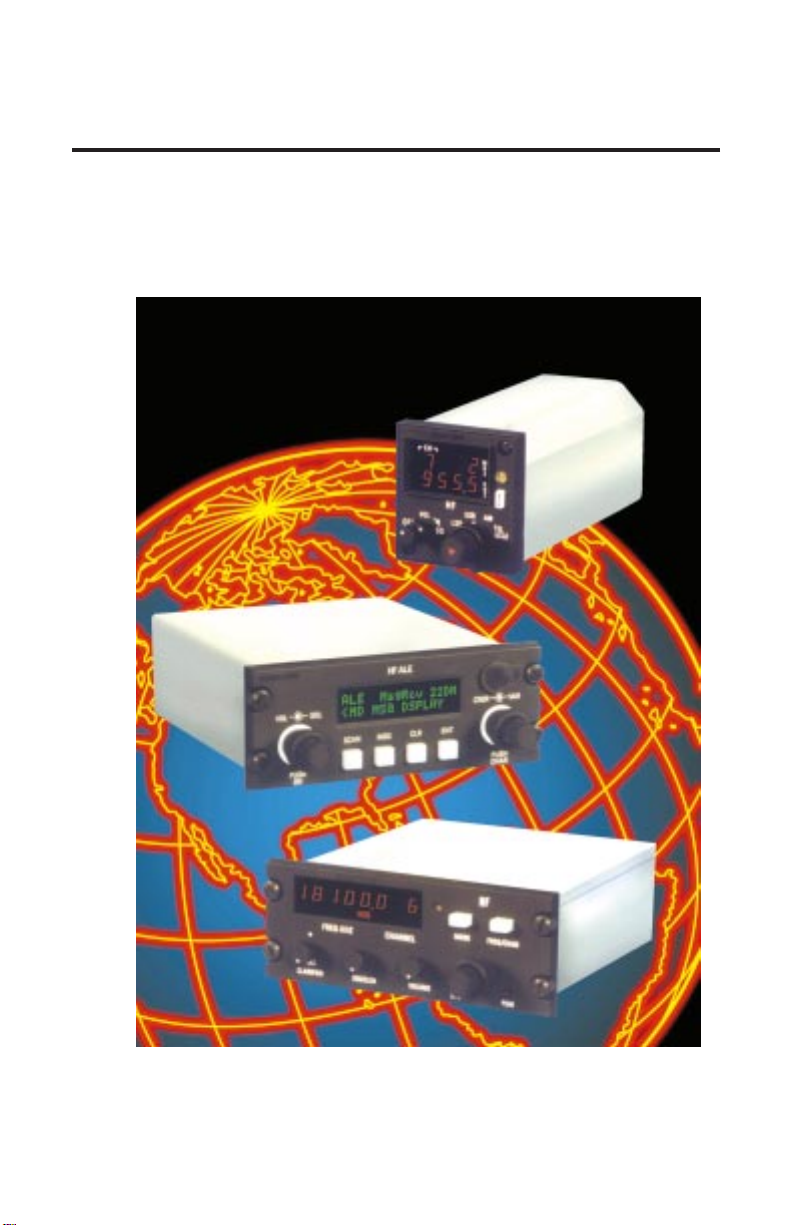
The KHF 950/990 is a compact, lightweight system to provide an
extensive range of operator benefits. It is designed with international
flight operations in mind to provide superior long range communications.
A basic KHF 950/990 system consists of either three or four units
including your choice of either a miniature Gold Crown III style (KFS
594) or two different Dzus rail-mounted control display units (KCU
951 & KCU 1051). Additional hardware is available to allow the KHF
950 system to tune most shunt and notch antennas used on some
corporate jet aircraft. It can also be installed in a dual configuration
sharing the same HF antenna, and yet provide a dual receive capability which many corporate users find highly desirable. The KCU
1051 will provide Automatic Link Establishment (ALE). This allows
automatic selection of the optimum frequency and linking to another
ALE system.
Microprocessor control of vital frequency selection functions provides
an unprecedented number of programmable channels, greater ease
of changing these channels on the ground or in the air, and direct
access to a full 280,000 operating frequencies from 2.0 to 29.9999
MHz. The control heads provide extreme ease in fully utilizing the
semi-duplex channels of the maritime radiotelephone (public correspondence) network.
There are three types of control heads available. The KCU 1051
control display unit provides Automatic Link Establishment (ALE)
capability. The KCU 1051 is a Dzus rail-mounted unit with 200 programmable channels, 100 for manual channels and 100 for ALE
channels, also all 245 ITU channels used by the maritime radiotelephone network are preprogrammed into non-volatile memory. No
additional programming of ITU channels is ever required. With the
KCU 951 Dzus rail-mounted control display unit, 99 pilot programmable channels are available. With the KFS 594 miniature control display unit and its associated remote adapter unit, 19 pilot programmable channels are available and, in addition, all 245 ITU channels used
by the maritime radiotelephone network are preprogrammed into
nonvolatile memory. When the KFS 594 Control Display Unit is used,
no additional programming of ITU maritime radiotelephone network
channels is ever required.
Rev. 0
Dec/96
KHF 950/990 Pilots Guide
i
Page 11

Introduction
High frequency radio opens a world of communication possibilities to
the pilot and his passengers, including long range contact with air
traffic control agencies over thousands of miles away, time and frequency standard broadcasts, Omega navigation station status
reports, weather and marine storm warnings, radiotelephone service
for personal messages and ARINC operational control services for
messages relating to flying operations.
The first section of this pilot’s guide deals with high frequency communications in general. A basic understanding of single sideband and
some of the conditions which influence HF communications is important to using the KHF 950/990 effectively and obtaining the maximum
benefit from its extensive capabilities.
The second section details the actual operation of the KHF 950/990
system and the final section of this pilot’s guide covers the wide variety of HF communications services which are available to the pilot
using the Bendix/King KHF 950/990.
ii
KHF 950/990 Pilots Guide
Rev. 0
Dec/96
Page 12

SECTION I
CHARACTERISTICS OF HF SSB
COMMUNICATIONS WITH AUTOMATIC
LINK ESTABLISHMENT.
ACRONYMS AND DEFINITIONS
ALE Automatic Link Establishment
AMD Automatic Message Display
CDU Control Display Unit
HF High Frequency
KPN King Part Number
LQA Link Quality Analysis
PC IBM compatible Personal Computer
REFERENCES
The following documents are referenced by this document.
Description
MIL-STD-188-141A Appendix A Notice 2
Automatic Link Establishment System, 10 September 1993
Federal Standard 1045A
Telecommunications:HF Radio Automatic LinkEstablishment,
24 January 1990
HF SSB COMMUNICATIONS
High frequency single side band communications achieve reliable
long range transmission and reception over distances of thousands
of miles. The primary reason is due to skywave propagation which
allows HF radio waves which are beamed toward outer space to be
reflected back toward the earth’s surface by the ionosphere. Another
reason is because of a transmission process known as single sideband which puts all the transmitter’s power into sending just a radio
Rev. 0
Dec/96
KHF 950/990 Pilots Guide
1-1
Page 13

Description
wave containing the intelligence to be communicated. Both of these
make HF radio highly useful to aircraft flying over water or desolate
land areas when they are out of reach of VHF communications which
are limited to line of sight transmissions. A familiarization with frequency, skywave propagation, amplitude modulation, single sideband
operation, suppressed carrier versus reduced carrier, simplex and
semi-duplex operation, and automatic link establishment will make
this pilot’s guide easier to use and understand.
The following explanations will help provide a base to build on as you
acquire experience in operating your KHF 950/990. If you have had
experience with HF radio previously, the following material will serve
as a review.
FREQUENCY
The frequency of a radio wave is the number of cycles of that radio
wave which pass a given point within one second. The longer the
wavelength, the lower the frequency. The frequency is often
expressed as cycles per second, with one complete wave representing a cycle. The term hertz (Hz) is more commonly used today to
represent one cycle per second. Expression of the measurement Hz
has a shorthand of its own. When thousands of Hz are expressed,
they are designated kilohertz (kHz), and millions of Hz as mega-
hertz (MHz). Thus the notation 29.9999 MHz represents a signal
which is passing a given point at 29,999, 900 cycles per second.
Expressed in kHz, the same Figure would read 29,999.9 kHz representing 29,999.9 thousand cycles per second. In using HF, you will
encounter both MHz and kHz notations for frequencies. KFS 594 and
KCU 951 control display units always express frequencies in terms of
kHz. The KCU1051 control display unit always expresses frequencies in terms of MHz.
The high frequency (HF) band , with which we are primarily con-
cerned in this pilot’s guide, covers from 2.0 MHz to 30 MHz (2,000
kHz to 30,000 kHz). The HF band lies between the medium frequency (MF) band and the very high frequency (VHF) band. Pilots are
familiar with the characteristics of MF frequencies through the use of
ADF equipment and know that these signals hug the ground and are
sensitive to variations in terrain and to atmospheric disturbances. On
the other hand, pilots know that VHF frequencies such as are used in
VOR navigation and normal communications with Air Traffic Control
facilities generally travel line-of-sight range and are not greatly affected by atmospheric disturbances. As will be discussed next, HF has
its own characteristics which allow long range communications to
take place.
1-2
KHF 950/990 Pilots Guide
Rev. 0
Dec/96
Page 14

Description
SKYWAVE PROPAGATION - WHICH FREQUENCY TO
USE?
As mentioned earlier, HF’s primary method of travel or propagation is
via skywaves which are radio waves that start out radiating into
space and are reflected off the ionosphere back to the earth’s surface. This reflecting of signals makes communications over very long
distances-under ideal conditions more than 4,000 miles and typically
in excess of 2,000 miles-possible. Because of variations in the ionosphere, HF communications require more analysis of conditions and
operational decisions (such as frequency selection) than VHF communications.
The ionosphere is a multi-layered band of electrically charged particles surrounding the earth. It varies in height above the surface of the
earth from approximately 30 to over 400 miles. The height and intensity varies from one location to the next and according to the season
of the year and the time of day.
Because HF radio waves depend upon the ionosphere for reflection,
their propagation is affected by changes in the ionosphere. It is
changes in the density of the electrically charged particles in the
ionosphere which cause propagation to improve or deteriorate. Since
the ionosphere is formed primarily by the action of the sun’s ultraviolet radiation, its thickness changes in relation to the amount of sunlight passing through it. Sunlight-induced ionization increases the particle density during the day and the absence of it reduces the particle
density at night. At midday, when the sun’s radiation is at its highest,
the ionosphere’s thickness may expand into four layers of ionized
gas. During the nighttime hours, the ionosphere diminishes, normally
merging into just one layer.
Solar disturbances including solar flares and magnetic storms can
cause propagation of HF radio waves to deteriorate rapidly. HF signals can also suffer interference from such atmospheric disturbances
as precipitation and thunderstorms.
The net result of all these factors is that because the ionospheric and
atmospheric conditions are constantly changing, HF communications
can vary in quality and strength. The signal received on the KHF
950/990 may be accompanied by a considerable amount of static
from atmospheric disturbances, or it may fade in and out at times
because each radio wave which hits the changing ionosphere may
be reflected differently. Your reception and transmission success may
vary from loud and clear to nonexistent depending on your selection
of frequency and the conditions in the atmosphere and the ionos-
Rev. 0
Dec/96
KHF 950/990 Pilots Guide
1-3
Page 15

Description
phere. One of the best things the pilot can do to assure the best possible HF communications, based on existing HF propagation conditions, is to select the proper frequency. A good rule of thumb for the
time of day is that the higher frequencies are best during daylight (10
to 29.9999 MHz) and lower frequencies work best at night (2 to 10
Mhz).
This rule of thumb can be explained by a mirror analogy. It is the
electrically charged particles in the ionosphere which reflect or bend
radio waves back toward earth like a mirror reflects light. Sunlight
induces ionization and increases the density of these particles in the
ionosphere during the day. The mirror becomes thicker and it reflects
higher frequencies better. When the sun goes down the density of
charged particles decreases and the ionosphere becomes a mirror
that can only reflect lower frequencies in the HF band.
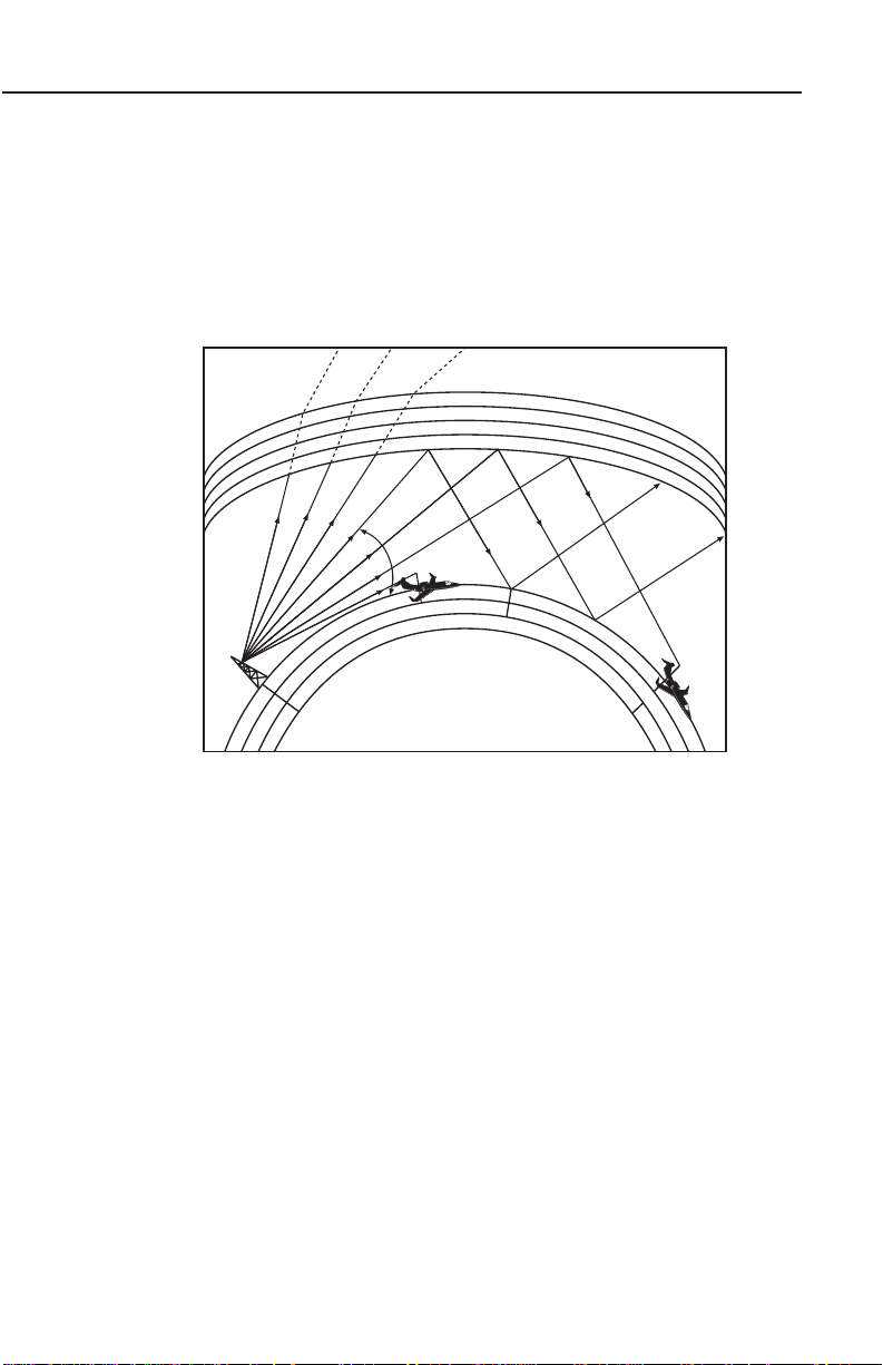
For any one particular frequency, as the angle at which an HF radio
wave hits a layer of the ionosphere is increased, a critical anglewill
be reached from which the wave will just barely manage to be reflected back to earth (Figure 1-1). Waves entering at sharper angles than
this will pass through this layer of the ionosphere and be lost in space
(or may reflect off another layer of the ionosphere).
Changing the frequency under the same conditions will change the
critical angle at which the HF radio waves will be reflected back to
earth. The highest frequency which is reflected back to the earth is
called the maximum useable frequency (MUF). The best HF communications are usually obtained using a frequency as close to the MUF
as possible since radio waves higher than this frequency are not
reflected and radio waves lower than this frequency will be partially
absorbed by the ionosphere.
You should also be aware of the possibility that you or the ground
station you are calling may be in a quiet zone. The linear distance
from the point of transmission to the point where the skywave returns
to earth is called the skip distance. There may be a quiet zone
between the end of the ground wave and the return of the skywave.
No communication can take place in this area. At any time, day or
night, there is a “window” of useable frequencies created by the
reflecting properties of the ionosphere. At night this “window” will normally be in the lower range of HF frequencies, and during the day it
will be in the higher range of frequencies.
Normally you will not know what the MUF is at any particular time and
location unless you have a table of propagation forecasts. Just
remember that the higher frequencies in the “window” of useable fre-
1-4
KHF 950/990 Pilots Guide
Rev. 0
Dec/96
Page 16
Description
quencies are likely to be the most effective. The closer a frequency is
to the MUF, the better it is likely to be.
The effect of solar disturbances including solar flares and magnetic
storms is to change the particle density in the ionosphere. Therefore,
the “window” of useable frequencies may begin to close, with radio
waves of frequencies in the lower range dropping out first as they are
absorbed by the ionosphere.
E
N
O
Z
IP
K
IONOSPHERE
AIRCRAFT
CRITICAL ANGLE
E
I
U
Q
E
C
N
A
T
S
DI
E
R
I
S
DE
EARTH
T
Z
O
N
E
S
K
Y
D
P
AT
H
W
D
A
I
S
V
T
E
A
N
C
E
AIRCRAFT
Z
O
N
E
REFRACTION
E
V
A
S
W
M
D
U
N
M
I
U
IN
O
M
R
G
Figure 1-1 Effects Of Different Skywave Paths
Next, the radio waves of upper frequencies in the useable “window”
may start to penetrate the ionosphere and go into outer space. It is
even possible for the entire “window” to close, particularly if you are
flying in a polar region in latitudes above 60 degrees north or 60
degrees south. Solar disturbances have the most negative effects on
HF communications in these regions.
If you are flying in polar regions and are having difficulty raising any
ground station located in the same region, remember this: even
though the “window” of useable frequencies may have closed in the
polar regions, another “window” may be open in regions closer to the
equator which are less affected by solar disturbances. Try calling a
station closer to the equator in latitudes lower than 60 degrees north
or 60 degrees south, and use a higher frequency. If you can raise a
station in these areas, that station may be able to relay your message.
Rev. 0
Dec/96
KHF 950/990 Pilots Guide
1-5
Page 17

Description
There are even times when solar disturbances improve the usability
of higher frequencies in the HF band, particularly in equatorial
regions. Another phenomenon which occurs during solar disturbances may allow you to communicate with a station even though the
“window” is closed. This is known as scatter propagation, in which a
radio wave is broken up in the ionosphere and scatters in various
directions. Refer to the discussion of geophysical alerts in Appendix
A for information on broadcasts which announce solar disturbance
phenomena, and how to interpret these broadcasts.
Because frequency propagation cannot be predicted with total accu-
racy, ground stations responsible for aircraft HF communications will
typically operate on several different frequencies within the HF band.
The pilot is then able to choose the optimum communication frequency for the existing ionospheric conditions.
One feature that will be particularly useful when a trial and error
method is used to find an HF frequency which is working well. This is
the system’s capability to be programmed by the pilot with 99 channels (using the KCU 951 Control Display Unit), 100 channels (using
the KCU1051 control display unit) or 19 (using the KFS 594 miniature
control display unit). Rather than having to select the four to six digits
each time you want to try another frequency, you can preprogram the
frequencies you need to contact a particular ground station. Then if
you call and fail to get through, you just change to another channel.
(Automatic channel selection for optimum communications reliability
is simplified with the addition of Automatic Link Establishment (ALE),
available on the KCU 1051 Control Display Unit.
NOTE: It is advisable to program at least three frequencies for each
station you plan to contact, in case one frequency suddenly becomes
unusable. During times of solar disturbances, a useable frequency
can fade out in less than a minute. And the “window” of useable frequencies can shift rapidly during solar disturbances or during sunset
and sunrise when the level of ionization in the ionosphere is changing rapidly.
Tables 1-1 and 1-2 show typical propagation distances after one
reflection from the ionosphere for various frequencies during different
hours of the day and for different seasons of the year. It may prove
helpful in selecting the optimum HF frequency for the communications distance your operation requires.
1-6
KHF 950/990 Pilots Guide
Rev. 0
Dec/96
Page 18

Description
Frequency (kHz)
4000 8000 12000 16000
Propagation (Miles)
Min Max Min Max Min Max Min Max
Hours After Sunset
1 50 250 200 1000 500 3500 750 6000
2 100 600 250 1500 500 3500 750 6000
3 100 600 250 2000 500 3500
4 100 800 250 2500
5 100 1000 250 2500
6 100 1500 400 3000
7 100 1500 500 3500
8 250 2000 750 4000
9 250 2500 750 4000
10 250 2500 750 4000
11 100 1000 500 2500
Hours After Sunrise
1 100 500 400 2000
2 0 100 400 2000
3 0 100 250 1500
4 0 100 250 1500 500 1000
5 0 100 250 1500 500 1500
6 0 100 250 1500 500 2500 750 4000
7 0 100 250 1500 500 3500 750 4000
8 0 100 250 1500 500 3500 750 4000
9 0 100 250 1500 500 3500 750 4000
10 0 100 250 1500 500 3500 750 4000
11 0 100 150 500 500 3500 750 6000
12 0 200 150 500 500 3500 750 6000
13 50 250 150 750 500 3500 750 6000
Table 1-1 Typical Frequency Propagation Spring And Summer
Rev. 0
Dec/96
KHF 950/990 Pilots Guide
1-7
Page 19

Description
Frequency (kHz)
4000 8000 12000 16000
Propagation (Miles)
Min Max Min Max Min Max Min Max
Hours After Sunset
1 100 600 400 2000 500 3500 750 6000
2 100 800 400 2000 500 4000 750 6000
3 100 1000 400 2000 500 4000
4 100 1000 400 2500 500 4000
5 100 1000 400 3000 500 4000
6 100 1500 400 3500
7 250 2000 400 4000
8 250 2500 500 4000
9 500 3000 500 4000
10 500 4000 500 4000
11 500 3000 750 5000
12 250 2500 750 5000
13 250 1500 500 2500
Hours After Sunrise
1 100 1000 400 2000
2 100 500 400 2000
3 0 100 400 2000 3500 750 4000
4 0 100 400 2000 500 3500 750 4000
5 0 100 250 1500 500 3500 750 4000
6 0 100 250 1500 500 3500 750 4000
7 0 100 250 1500 500 4000 750 5000
8 0 100 250 1500 500 4000 750 5000
9 0 100 250 1500 500 4000 750 6000
10 0 100 250 1000 500 3500 750 6000
11 0 250 250 1500 500 3500 750 6000
Table 1-2 Typical Frequency Propagation For Fall And Winter
1-8
KHF 950/990 Pilots Guide
Rev. 0
Dec/96
Page 20

Description
WHY SINGLE SIDEBAND IS IMPORTANT IN HF
COMMUNICATIONS
As mentioned earlier, there are two characteristics of HF SSB communications which allow long range capability. Skywave propagation
has been discussed in detail. The other characteristic is a transmission process known as single sideband. Single sideband (SSB) high
frequency (HF) communications was developed in the early 1950’s
as a means of increasing the effective range of HF signals. The KHF
950/990 is capable of both amplitude modulation (AM) operation,
such as is used in conventional VHF aircraft communications, and of
SSB operation.
AMPLITUDE MODULATION (AM)
In order to understand SSB operation, a discussion of AM operation
is helpful. Amplitude Modulation (AM) is a transmission process in
which the selected frequency (called the carrier frequency) and two
sidebands (which are frequencies above and below the carrier frequency) are generated and transmitted. (Figure 1-2.) It takes about
two-thirds of the transmitter’s power just to transmit the carrier frequency, yet the carrier does not contain any of the intelligence to be
communicated. Each of these sidebands contains all the intelligence
to be communicated. Standard broadcast stations (550-1600 kHz)
and short-wave broadcasts use AM since it allows simpler receivers.
NOTE: The use of lower sideband isn’t normally authorized for airborne HF use. It is normally disabled in the KHF 950/990, but can be
enabled for those who are authorized to use it.
AMPLITUDE MODULATION (AM)
fc = carrier frequency
fm = modulating frequency (voice)
fc-fm
LSB
fc fc+fm
USB
Figure 1-2 Amplitude Modulation
Rev. 0
Dec/96
KHF 950/990 Pilots Guide
1-9
Page 21
Description
SINGLE SIDEBAND (SSB)
fc = carrier frequency
fm = modulating frequency (voice)
fc-fm
LSB
fc fc+fm
USB
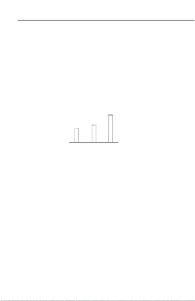
SINGLE SIDEBAND OPERATION
By electronically eliminating the carrier wave and one sideband, a
single sideband transmitter manages to pack all of its power in transmitting the remaining single sideband. (Figure 1-3). Either the upper
sideband (USB) or the lower sideband (LSB) can be used since each
sideband contains all the required intelligence. However, from a practical standpoint the USB is used almost exclusively in airborne HF
SSB operations and the LSB may be disabled. Upon receiving this
SSB signal, the receiver then generates the carrier frequency internally and combines it with the one sideband in such a way that the
intelligence (voice) can be heard and understood by the pilot.
SINGLE SIDEBAND (SSB)
Figure 1-3 Single Sideband
The result is that an SSB system has the effective transmit power of
AM units having many more times the transmitter power. Also, SSB
communications allow the frequency band to be utilized more efficiently since the space or “bandwidth” of only one sideband rather
than two sidebands is required to transmit the message.
SUPPRESSED CARRIER VS. REDUCED CARRIER
The single sideband (SSB) operation just described with the carrier
frequency virtually eliminated is actually referred to as single sideband suppressed carrier and is designated A3J. If just a small portion
of the carrier is transmitted along with the sideband, the operation is
referred to as single sideband reduced carrier and is designated A3A.
A3A was previously used in maritime radiotelephone but is not used
currently. Regulations still require its inclusion in equipment used in
conjunction with maritime radiotelephone. A3A is normally disabled
on the KCU 1051, but is harness selectable. A3A is normally internally disabled on the KCU 951 Control Display Unit. If it has been
enabled it is annunciated when both “AM” and “USB” are simultaneously displayed. The KFS 594 miniature control display unit allows
the A3A mode to be selected by rotating the mode selector to the
“A3A” position.
1-10
KHF 950/990 Pilots Guide
Rev. 0
Dec/96
Page 22

Description
SIMPLEX AND SEMI-DUPLEX OPERATION
The KHF 950/990 is capable of both simplex and semi-duplex operation.
Simplex operation means that communication signals are transmitted
and received on the same frequency. Simplex operations are used
when communicating with Air Traffic Control (ATC), for example.
Semi-duplex operation means that messages are transmitted on one
frequency and received on another. The HF operator selects separate transmit and receive frequencies, then keys the microphone to
transmit and releases the push-to-talk switch to receive. Semi-duplex
operation is usually used for maritime radiotelephone (public correspondence) communications.
AUTOMATIC LINK ESTABLISHMENT (ALE)
ALE is an HF radio management system that selects the optimum
frequency of transmission, places automatic or manual calls to link
one or more users, and communicates digital messages. The ALE
specification and waveform were adopted as standards by the US
government in September, 1988 as MIL-STD 188-141A (Appendix A)
for the military and as Federal Standard 1045 for civilian government
agencies.
The advent of ALE technology has changed HF communications by
allowing systematic and automatic real-time evaluation of HF communications paths, permitting automatic frequency selection.
Because of this, the operation of an HF radio with Automatic Link
Establishment is greatly simplified and the communications reliability
is increased. A KCU 1051 CDU is required when Automatic Link
Establishment features are desired.
FUNCTIONS OF HF RADIO AUTOMATION
There are many functions, that the HF Radio Automatic Link
Establishment System performs for you. They are Selective Calling
and Handshake, Scanning, Sounding, Polling, and Link Quality
Analysis and Channel Selection
SELECTIVE CALLING AND HANDSHAKE - The selective calling
and handshake function enables the establishment of a link between
two radios. It includes digital address selective calling, followed by an
exchange consisting of a response and acknowledgment, to produce
a handshake (the establishment of a communications link).
Rev. 0
Dec/96
KHF 950/990 Pilots Guide
1-11
Page 23

Description
SCANNING - All available stations continuously and rapidly scan
their receivers through their channels, seeking ALE calls. At any
time, a calling station may slowly scan its transmitter through their
channels, calling on each one, until answered on a channel that supports contact. This function enables the selection of a channel that
successfully supports contact, despite variations in propagation,
occupancy, and other traditional HF challenges.
SOUNDING - Sounding is a special beacon-like technique that
assists all listening stations in measuring the propagation from the
sounding station. The sounding station transmits its address on all
channels, and the other stations measure the quality of the received
signal. Sounding stations provide this service to other stations and
do not use the information themselves.
POLLING - Polling enables two radios to measure the propagation
characteristics for each channel’s receive and transmit path. Then the
information is stored in non-volatile memory.
LINK QUALITY ANALYSIS AND CHANNEL SELECTION - This
function enables the radio to measure the quality of the received signals (and thus the available links) and to select the best channel for
calling and communicating. This function allows a calling station to
initiate calling on the best known working channel and thereby speed
linking. It also minimizes unnecessary calling on marginal channels,
when a transmitting station knows how well its signal is being
received by the intended stations.
HOW ALE ASSURES THAT THE BEST COMMUNICATIONS LINK IS CHOSEN AUTOMATICALLY EVER Y TIME
With Automatic Link Establishment on the job, the radio constantly
scans the available channels for an ALE transmission. ALE transmissions are digitized HF signals. When an ALE transmission is
detected, the signal-to-noise ratio of that signal is retained in memory.
The next time a call is made, the radio uses that signal-to-noise ratio
to determine the best channel to use. This way the best channel is
always the one used, allowing you to have the best possible communications link all the time, in spite of the constantly changing thickness, density, and reflectivity of the ionosphere (a condition that is not
controllable). Every frequency reacts a little differently to random
changes in the ionosphere. The link quality for one frequency may
increase while it may decrease for another for the same random
changes.
1-12
KHF 950/990 Pilots Guide
Rev. 0
Dec/96
Page 24

Description
ALE relieves you of the burden of trying to manually detect and
compensate for random changes in the ionosphere and of
searching for a good channel to use. It lets you concentrate on
the message to be sent.
During the time when no call is present, the radio is squelched to
reduce noise in the cockpit. After a call is received, a sound like a
phone ringing is heard, the radio un-squelches, and you can commence a normal HF communication. ALE relieves you of the bur-
den of monitoring the radio for the presence of an HF call.
Rev. 0
Dec/96
KHF 950/990 Pilots Guide
1-13
Page 25

Description
This Page Intentionally Left Blank
1-14
KHF 950/990 Pilots Guide
Rev. 0
Dec/96
Page 26

Description
SECTION II
KHF 950/990
SYSTEM DESCRIPTION.
The KHF 950/990 is a solid-state HF single sideband transceiver system. The KHF 950 system can be controlled by either a KCU 1051
Dzus rail-mounted control display unit, a KCU 951 Dzus rail-mounted
control display unit, or a miniature KFS 594 Gold Crown III style control display unit. The KFS 594 requires an extra remote unit (KA 594)
which contains electronics associated with this miniature panelmounted control display unit. All the control units work in conjunction
with a KAC 952 power amplifier/antenna coupler and a KTR 953
receiver/exciter.
The KHF 990 system can be controlled by either a KCU 1051 or the
KFS 594 Control Display Unit. These control units work with the KAC
992 Antenna Coupler and a KTR 993 receiver/transmitter.
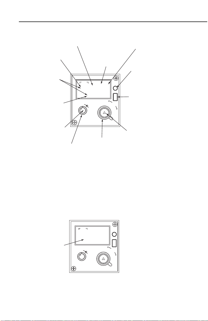
KCU 1051 CONTROL DISPLAY UNIT
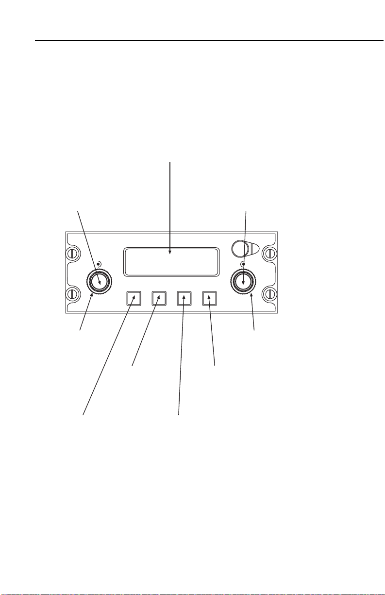
The KCU 1051 Control Display Unit (Figure 2-1) adapts the existing
KHF 950 and KHF 990 High Frequency Radio systems for use with
Automatic Link Establishment, providing the pilot’s display and control interface. Frequency, channel, mode, ALE address, audio gain,
and squelch level selections are entered via its controls. Fault monitoring and fault annunciation are also provided by the KCU 1051.
The KCU 1051 provides the pilot access to 100 manual channels,
100 ALE channels, and 245 ITU channels to interface with maritime
radiotelephone networks. The KCU 1051 uses a liquid crystal display
to show frequency, channel, and mode of operation. The manual
and ALE channels can be easily programmed by the pilot on the
ground or in the air, and the nonvolatile memory stores this information even when the system is turned off.
Rev. 0
Dec/96
KHF 950/990 Pilots Guide
2-1
Page 27
Description
Display
The display screen is capable of displaying 2 lines of 16
(upper or lower case) characters. Information is
presented in formatted pages. The main display pages
are accessed by placing the cursor over the
operations/mode field (ALE) and rotating the VAR knob
until the desired page is displayed. To display a subpage of a main page see Secton III, Operation..
VOLUME knob
The VOLUME knob performs two functions.
Rotate the VOLUME knob to control the
audio output level. Push the VOLUME knob
to the in position to apply power to the unit or
pull the VOLUME knob to the out position to
remove power from the unit.
SQUELCH knob
Rotate SQUELCH
knob to control
the squelch
threshold level.
CURSOR knob
Rotate CURSOR knob to move
cursor from one field to next
field or one character to next
character when in CHAR MODE.
VAR knob
The VAR knob performs two functions.
Rotate knob to vary data under cursor.
Toggle the momentary switch. VAR knob
to the in position to select CHAR cursor
mode and then toggle again to select
FIELD cursor mode.
HF ALE
SCAN
VOL SQL CRSR VAR
MSG CLR ENT
PUSH
ON
PUSH
CHAR
B
OOOO Scan 100RM
ALE15CHARADDRESS
CLR key
By pushing the CLR
key you can cancel
changes made by the
operator or exit the
programming page.
ENT key
Pressing the ENT key
stores changes made
to the cursored field.
MSG key
The MSG key displays
the message page
where system
messages and ALE
AMDs can be reviewed
SCAN key
The SCAN key starts and
stops scanning and it causes
the radio to hang-up from an
ALE link. The SCAN key can
also be used to abort an
initiated call.
2-2
Figure 2-1 KCU 1051 Control Display Unit
KHF 950/990 Pilots Guide
Rev. 0
Dec/96
Page 28

Description
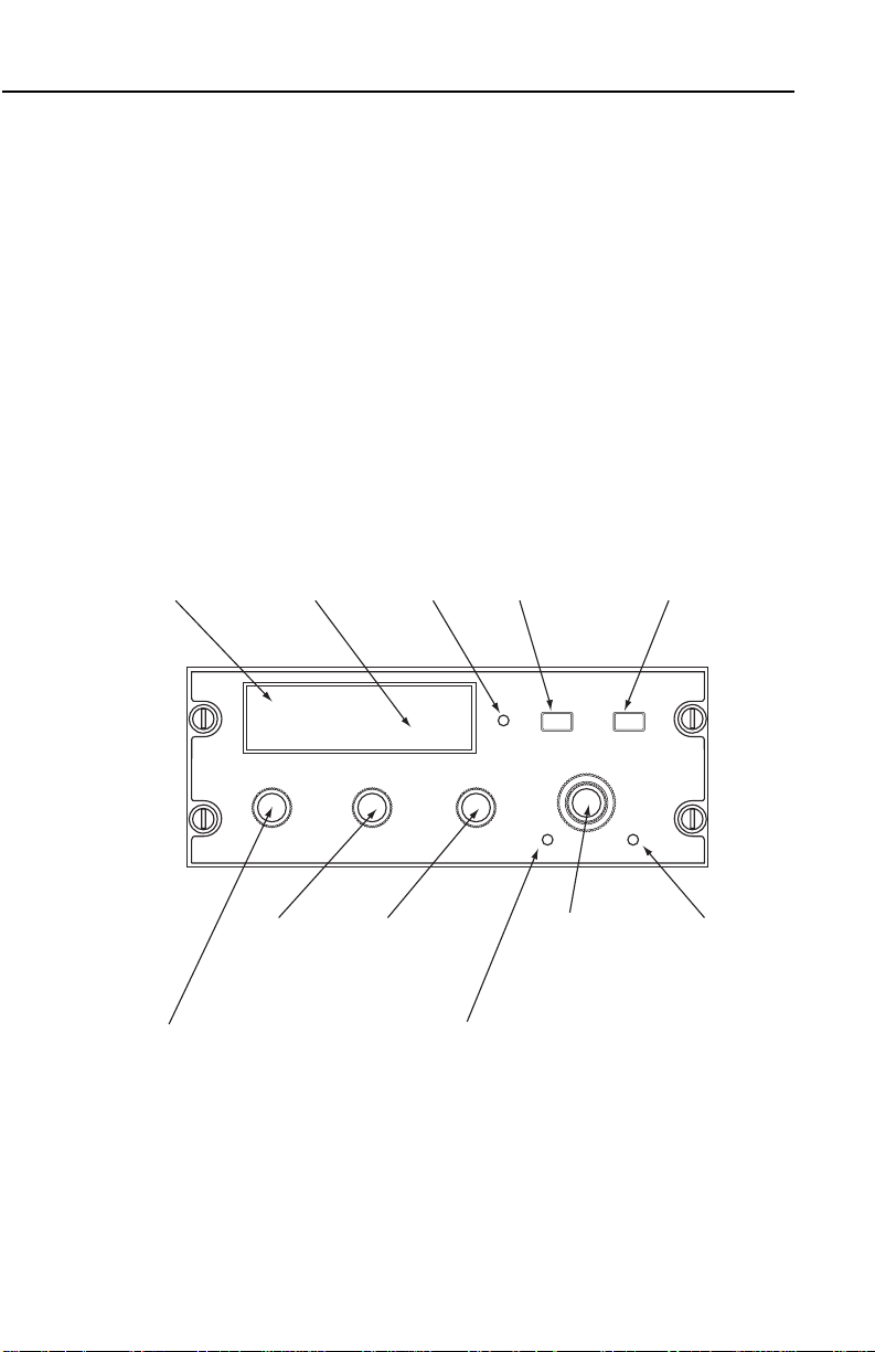
KFS 594 CONTROL DISPLAY UNIT
The KFS 594 (Figure 2-2) provides the pilot with access to 19 programmable channels plus a full 280,000 operating frequencies in the
2.0 to 29.9999 MHz range. In addition, all 245 ITU maritime radiotelephone network (public correspondence) channels have been stored
in nonvolatile memory along with the appropriately paired transmit
and receive frequencies. Thus, to call up a radiotelephone channel,
the pilot need only select “423” for WOM in Ft. Lauderdale, Fla., for
example, rather than having to program 4425.6 kHz as the transmit
frequency and 4131.2 kHz as the receive frequency (see WOM channel/frequency chart, Figure 7-3). The KFS 594 is a miniature Gold
Crown III style control display unit which uses electronic gas discharge readouts to display frequency and channel information. All
necessary controls for operation of the KHF 950/990 system, including programming of all preset channels, are on the KFS 594.
The 19 channels can be easily programmed by the pilot on the
ground or in the air, and the nonvolatile memory stores this information and the 245 ITU maritime radiotelephone channels even when
the system is turned off.
Rev. 0
Dec/96
KHF 950/990 Pilots Guide
2-3
Page 29
Description
1
S
T
HF
OFF
TELAM
USB
LSB
A3J
A3A
VOL
SQ
2236
CH
M
H
Z
K
H
Z
KFS 594 in
A3J (or A3A)
MODE
Mairitime
radiotelephone ITU
channel number
appears in this area
of the display when
EMISSION MODE
switch is in A3J or
A3A position.
1
S
T
HF
OFF
TELAM
USB
LSB
A3J
A3A
VOL
SQ
1231
12 - 31
CH
M
HZT
X
K
H
Z
Pilot programmed
channel number
appears in this area
of the display when
using one of the 19
programmable
channels.
Gas discharge
readouts display all
frequencies and
preset channel
numbers.
Last for digits (kHz)
of operating
frequency are
display in this area
of the display with
EMISSION MODE
switch in LSB*, USB
or AM position.
OFF/VOLUME knob
(inner concentric)
turns system on and
adjusts audio
volume.
SQUELCH knob
(outer concentric)
helps reduce
background noise
when not receiving
a signal.
EMMISSION MODE
switch (outer
concentric) selects
lower sideband
(LSB), AM modes,
and a choice of
either A3J or A3A in
maritime
radiotelephone
network channels.
FREQUENCY/CHANNEL
CONTROL knob (inner
concentric) allows the pilot
to perform a variety of
channel and frequency
changing functions.
Depressing switch causes
flashing "cursor" to move to
the digit that the pilot desires
to change. Appropriate
frequency or channel is then
selected with rotary action.
This switch also serves as
the clarifier function to
adjust receive frequency and
improve speech quality in
single sideband operating
mode.
STO (store) switch
stored displayed
frequency in memory.
When pressed
simultaneously with
microphone push-to-talk
switch, transmits 1,000
Hz "operator attention"
tone as required by
some Canadian
radiotelephone stations.
Photocell dims
display
automatically.
Smaller gas
discharge
characters display
transmit indication.
With EMMISSION
MODE switch in
LSB*, USB or AM
position, the first
one or two digits
(MHz) of the
operating frequency
are displayed here.
Dash indicates unit
is in the PROGRAM
MODE.
2-4
Figure 2-2 KFS 594 Control Display Unit
KFS 594 in A3J (or A3A) Mode
Figure 2-3 KFS 594 in A3J (or A3A) Mode
KHF 950/990 Pilots Guide
Rev. 0
Dec/96
Page 30
Description
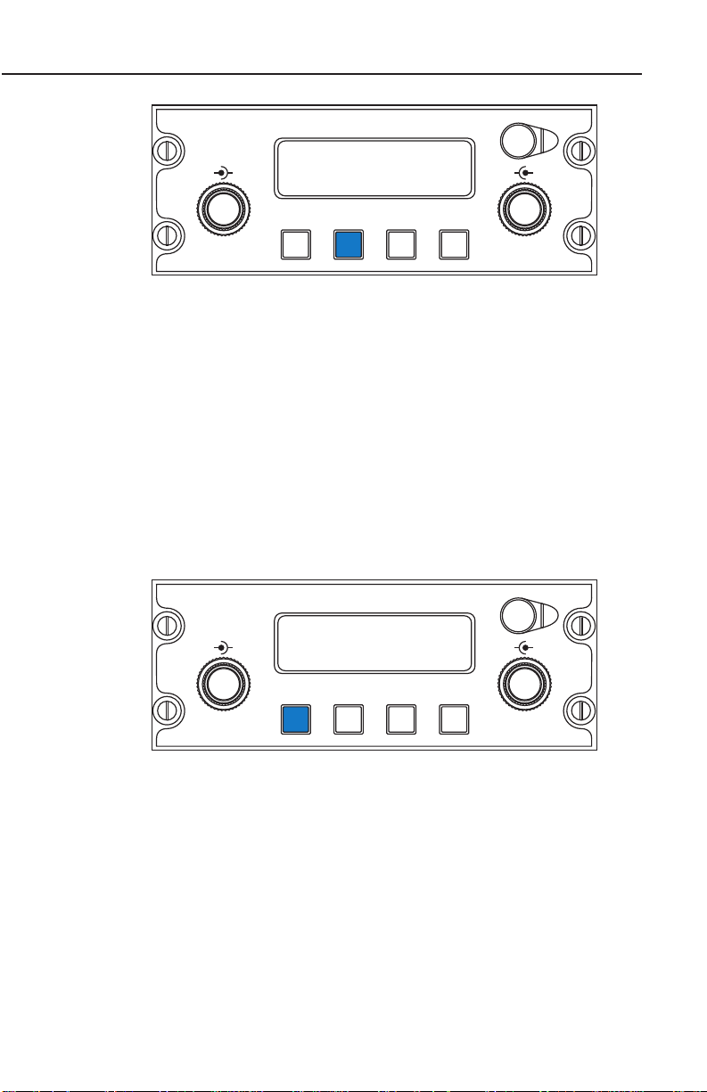
KCU 951 CONTROL DISPLAY UNIT
The KCU 951 (Figure 2-4) provides the pilot access to 99 programmable channels plus a full 280,000 operating frequencies in the 2.0 to
29.9999 MHz range. It provides semi-duplex capability through the 99
programmable channels to interface with maritime radiotelephone
networks. A Dzus rail-mounted control display unit, the KCU 951,
uses electronic gas discharge readouts to display frequency, channel
and mode of operation. All necessary controls for operation of the
KHF 950/990 system, including programming of all preset channels,
are on the KCU 951. The 99 channels can be easily programmed by
the pilot on the ground or in the air, and the nonvolatile memory
stores this information even when the system is turned off.
Smaller gas
Gas discharge
readouts display all
frequncies and
preset channel
numbers.
discharge
characters display
emmision mode,
transmit indicator
and program mode
indication.
ı
12345.6 99
USBAMLSB PGMTX
PULL
CLARIFIER knob adjusts receive frequency to
improve speech quality in a single sideband
operating mode. Use of this control is only
required when station-to-station frequency
difference is significant.
FREQ KHZ CHANNEL
CLARIFIER
SQUELCH knob
helps cut out
background noise
when not
receiving a signal.
SQUELCH
Photocell
dims display
automatically.
OFF/VOLUME
knob turns
system on and
adjusts audio
volume.
OFF
VOLUME
STO (store)
switch stores
displayed
frequency and
emmission mode
in memory.
EMMISSION MODE
switch selects lower
sideband (LSB
where aproved),
upper sideband
(USB) or AM
modes.
HF
MODE FREQ CHAN
STO PGM
Concentric
Frequency/Channel
knobs set frequency
or select preset
channel.
FREQ/CHAN
(frequency/channel)
switch selects either
direct tuning or
preset channel
operation.
PGM (program)
switch permits pilot
to change frequncy
and emission mode
of preset channel.
Rev. 0
Dec/96
Figure 2-4 KCU 951 Control Display Unit
KHF 950/990 Pilots Guide
2-5
Page 31

Description
KHF 950 REMOTE UNITS
KAC 952 POWER AMPLIFIER/ANTENNA COUPLER
The KAC 952 Power Amplifier/Antenna Coupler unit (Figure 2-6) is
mounted near the HF antenna to optimize transmission efficiency.
The KAC 952 is all solid-state and can be mounted outside the aircraft pressure vessel for operation at any altitude up to 55,000 feet.
The power amplifier in the KAC 952 amplifies the signal from the KTR
953 Receiver/Exciter into a 150 watt peak envelope power (PEP)
transmitted signal in single sideband operation and 35 watts in AM
operation.
Figure 2-5 KAC 952 Power Amplifier/Antenna Coupler
Because the KHF 950 operates over such a broad frequency range
(2.0 to 29.9999 MHz), it is impossible to optimize the actual aircraft
HF antenna length for each frequency.
Instead, by changing its electrical impedance, the automatic antenna
coupler in the KAC 952 tunes the antenna to each frequency, making
the antenna appear to the transmitted signal as though it were the
optimum physical length.
2-6
KHF 950/990 Pilots Guide
Rev. 0
Dec/96
Page 32

Description
KTR 953
B
KTR 953 RECEIVER/EXITER
The KTR 953 remote unit (Figure 2-6) contains the receiver and the
exciter for the KHF 950. The exciter is a transmitter which produces a
very low power signal which is fed to the power amplifier in the KAC
952.
Figure 2-6 KTR 953 Receiver/Exiter
NOTE: Only the KTR 953-01,11,41,53 (KPN 064-1015-01) is compatible with standard SELCAL decoder units (not furnished). The
KTR 953-01 and the SELCAL decoder are both necessary to obtain
SELCAL operation. See page 19 for additional information on SELCAL.
NOTE: The KHF 950 is designed for continuous duty cycle (transmit)
at 150 watts PEP for voice transmission on upper sideband (USB).
On all other type transmissions, the unit will operate continuously;
however, after an extended period of transmission the power will
begin to back down to protect the power amplifier from overheating.
The exact time required depends on the ambient temperature. For
example, after seven minutes transmission in the AM Mode the
power is approximately 1/3 of normal power output. A duty cycle of 3
minutes on and 3 minutes off will insure maximum power output.
Rev. 0
Dec/96
KHF 950/990 Pilots Guide
2-7
Page 33

Description
KTR 953
B
KTR 953
B
*KCU 951 Control Display Unit
KTR 953
Receiver/Exciter
KA 158
Bridging Amps
KAC 952
Power Amplifier/
Antenna Coupler
Aircraft
HF Antenna
KA 160 Antenna Changeover Unit
(For long wire antennas).
or
KA 162 Antenna Changeover Unit
with external capacitor
(For shunt or short wire antennas).
*KCU 951 Control Display Unit
KTR 953
Receiver/Exciter
KAC 952
Power Amplifier/
Antenna Coupler
*A KCU 1051Control Display Unit or a miniature
KFS 594 Control Display Unit with its associated
KA 594 adapter may be substituted for the
KCU 951 Control Display Unit.
FREQ KHZ CHANNEL
CLARIFIER
PULL
SQUELCH
OFF
VOLUME
STO PGM
MODE FREQ CHAN
HF
ı
12345.6 99
USBAMLSB PGMTX
FREQ KHZ CHANNEL
CLARIFIER
PULL
SQUELCH
OFF
VOLUME
STO PGM
MODE FREQ CHAN
HF
ı
12345.6 99
USBAMLSB PGMTX
ADDITIONAL KHF 950 INSTALLATION OPTIONS
While the standard KHF 950 system requires a wire antenna of only
10 feet, shorter wire antennas as well as “shunt” or “notch” antennas
may also be tuned with additional hardware.
Special hardware is also available to allow dual KHF 950 systems
(Figure 2-7) to operate from a single antenna and provide a dual
receive capability.
Figure 2-7 Dual KHF 950 System Configuration
2-8
KHF 950/990 Pilots Guide
Rev. 0
Dec/96
Page 34

SINGLE KHF 950 SYSTEM CONFIGURATION (SHUNT OR
KTR 953
B
*KCU 951 Control Display Unit
KTR 953
Receiver/Exciter
KAC 952
Power Amplifier/
Antenna Coupler
Aircraft
HF Antenna
KA 161 Antenna
External Capacitor Unit
*A KCU 1051Control Display Unit or a miniature
KFS 594 Control Display Unit with its associated
KA 594 adapter may be substituted for the
KCU 951 Control Display Unit.
FREQ KHZ CHANNEL
CLARIFIER
PULL
SQUELCH
OFF
VOLUME
STO PGM
MODE FREQ CHAN
HF
ı
12345.6 99
USBAMLSB PGMTX
SHORT WIRE ANTENNAS)
Description
Figure 2-8 Single KHF 950 System Configuration
(Shunt or Short Wire Antennas)
Rev. 0
Dec/96
KHF 950/990 Pilots Guide
2-9
Page 35

Description
KHF 990 REMOTE UNITS
KAC 992 PROBE/ANTENNA COUPLER
The KAC 992 Probe/Antenna Coupler (Figure 2-9) is a combined
Whip Antenna and Coupler designed to automatically match the
impedance of the antenna to 50 ohms over the full frequency range
of 2.0 to 29.999 MHz. The KAC 992 Coupler is hermetically sealed,
so may be mounted either totally external or with coupler section
mounted internally and the antenna protruding through a clearance
hole in the aircraft skin.
2-10
Figure 2-9 KAC 992 Probe/Antenna Coupler
KHF 950/990 Pilots Guide
Rev. 0
Dec/96
Page 36

Description
D.C. POWER
REMOTE
ANTENNA
KTR 993
ı
KTR 993 RECEIVER/EXITER/AMPLIFIER
The KTR 993 (Figure 2-10) HF Transceiver contains the
receiver/exciter, RF power amplifier, Lowpass filters, and control circuitry necessary for generation of SSB and AME signals. It is capable of 150 watts PEP output on any of 280,000 frequencies from 2 to
29.9999 MHz.
Figure 2-10 KTR 993 Receiver/Exiter/Amplifier
NOTE: The KHF 990 is designed for continuous duty cycle (transmit)
at 150 watts PEP for voice transmission on upper sideband (USB).
On all other type transmissions, the unit will operate continuously;
however, after an extended period of transmission the power will
begin to back down to protect the power amplifier from overheating.
The exact time required depends on the ambient temperature. For
example, after seven minutes transmission in the AM Mode the
power is approximately 1/3 of normal power output. A duty cycle of 3
minutes on and 3 minutes off will insure maximum power output.
Rev. 0
Dec/96
KHF 950/990 Pilots Guide
2-11
Page 37

Description
*KCU 951 Control Display Unit
KTR 993
Receiver/Exciter/Amplifier
KAC 992
Probe/Antenna Coupler
Aircraft
HF Antenna
*A KCU 1051Control Display Unit or a miniature
KFS 594 Control Display Unit with its associated
KA 594 adapter may be substituted for the
KCU 951 Control Display Unit.
FREQ KHZ CHANNEL
CLARIFIER
PULL
SQUELCH
OFF
VOLUME
STO PGM
MODE FREQ CHAN
HF
ı
12345.6 99
USBAMLSB PGMTX
D.C. POWER
REMOTE
ANTENNA
KTR 993
ı
SINGLE KHF 990 SYSTEM CONFIGURATION
Figure 2-11 Single KHF 990 System Configuration
2-12
KHF 950/990 Pilots Guide
Rev. 0
Dec/96
Page 38

Operation
SECTION III
OPERATING THE KHF 950/990
KHF 950/990 GENERAL OPERATING INFORMATION
PREFLIGHT INSPECTION
During preflight walk around inspection, it’s important to check the HF
antenna for structural integrity. Long wire antennas may be used with
the KHF 950, and these can be damaged by ice accumulation in
flight or broken by improper aircraft ground handling or fueling operations.
A ground check of the KHF 950/990 is advisable, particularly if it is
going to be the primary source of contact with Air Traffic Control during over water flights. (It may be advisable to consider the operational
benefit of installing dual KHF 950 radios when HF communications
are the primary source of contact with Air Traffic Control. A second
unit would provide a backup and a means of monitoring other HF services while the first radio is tuned to an ATC frequency.)
To check for proper antenna tuning, allow the KHF 950/990 to warm
up until the display becomes active (up to two minutes), select an
authorized frequency and press the microphone key. When using a
KCU 1051, “TUNE IN PROGRESS” will be displayed if the channel
had not been previously tuned. When tuning stops, the frequency
display reappears. If a fault is indicated, refer to the section on Fault
Indication in the pilots guide.
NOTE: When using the KCU 951 or the KFS 594, the TX annunciation should flash and the frequency display blank as the antenna coupler tunes the antenna. When the tuning sequence is complete the
TX stops flashing and the frequency display reappears. If the TX fails
to stop flashing refer to the section on Fault Indication in this pilot’s
guide.
To check for proper operation of the system, transmit a radio check
on an authorized frequency. Make sure you can transmit and receive,
using a frequency which is suitable for the time of day.
NOTE: The warm up period is for a crystal oven to heat up which
assures an extremely high degree of frequency stability under varying environmental conditions.
Rev. 0
Dec/96
KHF 950/990 Pilots Guide
3-1
Page 39

Operation
CAUTION: When performing a ` radio check on the ground,
make certain that all personnel are clear of the HF antenna
before transmitting. SERIOUS RF BURNS CAN RESULT FROM
DIRECT CONTACT WITH THE ANTENNA OR ANTENNA TERMINAL WHEN THE SYSTEM IS TRANSMITTING.
ANTENNA TUNING
When using a KCU 1051 control display unit, the antenna coupler
tune information is stored in non-volatile memory. This means that
retunes are required only when new frequencies are entered into the
channel non-volatile memory. For semi-duplex channels both the
receive and transmit frequency is tuned to provide optimum performance.
When using a KCU 951 or a KFS 594 the antenna coupler retunes
the antenna under the following conditions:
1. When the system is first turned on (and warmed up) and the mic
key is pressed.
2. When a new channel or frequency is selected and the mic key is
pressed. Always initiate a tuning sequence after selecting a new frequency or channel. A tuned antenna improves receiver performance.
3. When an existing channel or frequency is being used while the
unit senses an improper match and the mic key is pressed.
The antenna coupler is always utilized when transmitting (regardless
of mode) and while receiving in the simplex mode (after mic key is
pressed for tuning). The antenna coupler is bypassed during receive
when operating in semi-duplex or receive-only channelized operation.
The system is then functioning as a receiver connected directly to the
HF antenna.
F AULT INDICATION
When using a KCU 1051, if the system detects a fault, a flashing “M”
appears in the upper right corner of the display, and a fault message
is displayed on the second line. The fault message reads “High
VSWR” if there is an antenna problem, otherwise it reads “Fault see
MSG pg”. If connected, the Remote light also annunciates. The fault
messages can be viewed on the message page by pressing the
MSG key. If a High VSWR fault occurs, key the microphone to cause
the automatic antenna coupler to begin a new tuning cycle to clear
the fault.
3-2
KHF 950/990 Pilots Guide
Rev. 0
Dec/96
Page 40

Operation
Using the KCU 951 or KFS 594, if the system detects a fault during
transmission or during the tuning of the antenna coupler, the frequency digits on the display begin to flash. Simply key the mic and the
automatic antenna coupler begins a new tuning cycle to clear the
fault.
TUNING FAULTS
If the antenna coupler is unable to find an acceptable
frequency/antenna match, the fault indication continues at the end of
the tuning cycle. If repeated antenna tuning cycles fail to clear the
fault indication from the display, there is probably an equipment malfunction.
KHF 950/990 CONTROLS-GENERAL
Operating the KHF 950/990 requires that the pilot first determine the
correct mode to match the ground station, whether it be upper sideband (USB), lower sideband (LSB), or AM. Correct mode selection is
essential for successful contact with a ground station. Most stations
use USB mode, but some continue to use AM. Also, the pilot must
determine whether simplex, semi-duplex or receive-only frequency
operation is required to match the operation of the desired ground
station.
THERE ARE SEPARATE OPERATING SECTIONS ON EACH OF
THE CONTROL DISPLAY UNITS. READ ONLY THE SECTION
WHICH PERTAINS TO THE CONTROL DISPLAY UNIT YOU HAVE
INSTALLED WITH YOUR KHF 950/990.
Rev. 0
Dec/96
KHF 950/990 Pilots Guide
3-3
Page 41

Operation
KCU 1051 CONTROL DISPLAY UNIT OPERATION
This section describes the KCU 1051 Control Display Unit controls
and display. The ALE database is preloaded as described in Section
XII.
KCU 1051 GENERAL OPERATING INFORMATION
KCU 1051 CONTROL DESCRIPTION
The controls on the KCU 1051 CDU are: PUSH/ON control, VOL
knob, SQUELCH knob, PUSH CHAR, CURSOR knob, VAR knob,
CLR key, ENT key, SCAN key, MSG key,
PUSH ON/VOL
This control (Figure 3-1) turns the system on and off and controls volume. Push the VOL knob to the in position to apply power to the unit
or pull the VOL knob to the out position to remove power from the
unit. Rotate the VOL knob to control the audio output level.
B
VOL SQL CRSR VAR
PUSH
ON
OOOO SSSSSSSSSRM
1234567890123456
SCAN
HF ALE
MSG CLR ENT
PUSH
CHAR
Figure 3-1 Push ON/VOL
SQUELCH (SQL)
Squelch (Figure 3-2) is set by rotating the SQL knob counterclock-
wise until background noise is heard, and then turning it clockwise
until background noise is eliminated or just barely audible. When
using ALE, the squelch normally is turned off because ALE turns off
the audio until a call is received.
3-4
KHF 950/990 Pilots Guide
Rev. 0
Dec/96
Page 42

Operation
B
VOL SQL CRSR VAR
PUSH
ON
OOOO SSSSSSSSSRM
1234567890123456
SCAN
HF ALE
MSG CLR ENT
PUSH
CHAR
Figure 3-2 Squelch Control
CURSOR (CRSR)
The cursor is moved by rotating the CRSR knob (Figure 3-3). The
cursor moves from one field to the next field when in the field cursor
mode. The cursor moves from one character to the next character
when in the character cursor mode.
B
VOL SQL CRSR VAR
PUSH
ON
OOOO SSSSSSSSSRM
1234567890123456
SCAN
HF ALE
MSG CLR ENT
PUSH
CHAR
Figure 3-3 Cursor Control
VAR/PUSH CHAR
The VAR knob (Figure 3-4) performs two functions. Rotate the VAR
knob to change data under the cursor. Pressing the VAR knob toggles the cursor between field and character modes. In field cursor
mode the cursor covers the entire field. In character cursor mode the
cursor covers a single digit, or character, within a field.
Rev. 0
Dec/96
KHF 950/990 Pilots Guide
3-5
Page 43

Operation
HF ALE
SCAN
VOL SQL CRSR VAR
MSG CLR ENT
PUSH
ON
PUSH
CHAR
B
OOOO SSSSSSSSSRM
1234567890123456
HF ALE
SCAN
VOL SQL CRSR VAR
MSG CLR ENT
PUSH
ON
PUSH
CHAR
B
OOOO SSSSSSSSSRM
1234567890123456
HF ALE
SCAN
VOL SQL CRSR VAR
MSG CLR ENT
PUSH
ON
PUSH
CHAR
B
OOOO SSSSSSSSSRM
1234567890123456
Figure 3-4 Var Control
CLEAR (CLR)
The CLR key (Figure 3-5) cancels changes made to the active field or
exits a programming page..
Figure 3-5 CLR key
ENTER (ENT)
The ENT key (Figure 3-6) stores changes made to the active field, or
activates the selected mode.
3-6
Figure 3-6 ENT key
KHF 950/990 Pilots Guide
Rev. 0
Dec/96
Page 44
Operation
HF ALE
SCAN
VOL SQL CRSR VAR
MSG CLR ENT
PUSH
ON
PUSH
CHAR
B
OOOO SSSSSSSSSRM
1234567890123456
HF ALE
SCAN
VOL SQL CRSR VAR
MSG CLR ENT
PUSH
ON
PUSH
CHAR
B
OOOO SSSSSSSSSRM
1234567890123456
Figure 3-7 MSG Key
MESSAGE (MSG)
The MSG key (Figure 3-7) displays the message page where system
messages, and ALE, digital messages (AMDs) can be reviewed.
The MSG key displays the message page where system messages,
ALE AMDs, or modem messages can be reviewed.
SCAN
The SCAN key starts and stops scanning and it causes the radio to
hang-up from an ALE call. The SCAN key can also be used to abort
an initiated call.
Figure 3-8 Scan Key
Rev. 0
Dec/96
KHF 950/990 Pilots Guide
3-7
Page 45

Operation
KCU 1051 DISPLAY AND CONTROL OPERATION
This section describes the user interface to the HF system.
This is a brief explanation of the operation of the KCU 1051 display
and controls used to enter the manual channel and ALE databases
(Figure 3-9).
B
VOL SQL CRSR VAR
PUSH
ON
ALE MsgRcv 22DM
<MD MSG DSPLAY
SCAN
HF ALE
MSG CLR ENT
PUSH
CHAR
Figure 3-9 KCU 1051 Front Panel Controls
And Indicators
DISPLAY
The display has 2 lines of 16 characters. Both upper and lower case
letters can be displayed. The use of upper and lower case letters
makes some abbreviations easier to read, for example “MSGRCV”
could be “MsgRcv”
PAGES
The display is arranged in pages. A page is a presentation of specific
data in an organized format. Figure 3-10 shows the page organization. There are four top level pages; ALE, SEND, MAN and SYS.
ALE mode is enabled on the ALE and SEND pages. The MAN (manual) page allows the manual database of 100 channels, to be
reviewed, entered, and used for receive and transmit. The ALE
channels can also be reviewed and used for receive and transmit on
the manual page. However, the ALE database can be programmed
only in the sub-pages below the SYS (system) page. On the System
Page, placing the cursor over the top right field allows selection of
subsequent system pages.
3-8
KHF 950/990 Pilots Guide
Rev. 0
Dec/96
Page 46

Operation
Bold= Cursorable field
ALE scan 100R
DUSTOFF6
ALE Calling 12T
DUSTOFF6
ALE Linked 12R1
DUSTOFF6
ALE MsgRcv 5D
RETURNTO
ALE SoundR5D
BRAVO4
ALE SoundT23T
KR1
SEND Message 10
STOP AND
MAN ChMan 23R
R&T 23.3950 USB
SYS Test
ENT to Start
SEND SoundAS
KR1
SEND LQA
DUSTOFF
SYS RevNum
SWMOD RR/VV
SYS Program
} Messages
SYS LQAscore
ENT to review
LQA scores
| displayed
any page
MSG msg-type
message shown
TEST: Passes
CLR to exit
Edit_TX10
MISSION
Rev_RX 3
RETURNTO
Del_RX 3
RETURNTO
Copy_RX 2
ToTx 3
Intervals
} ActvLim 5Min
Enables
} AutoSound ON
Bright Panel
ENT to set Max
ALE-channel 11
R&T 23.4560 USB
ChGrp 23S ADD 32
12122431
ScanList
Use ChGrp 1S
Tune All ? YES
Caution HF xmit
Need Tune ###
Completed ###
ClearTunes ? NO
Sets all untuned
Addr Self 20
} KR1
} Messages
| Operation
| Channel
{ Address
} ActvLim
| ScnRate
| Sound
{ CallTime
} Auto Sound
| LQA in call
| Message Rx
| Anycall Rx
| Allcall Rx
| Wildcard
{ Roll Over
ALE idle state
scanning or single
channel
ALE call to address
on second linel
Linked to address
on second line
Receiving AMD
Msg scrolls across
second line
Sound received from
address on second line
Sounding on channel 23
using address on
second line
Perform LQA
exchange with
address on second line
Sound with
self address on
second line
Send AMD msg
Mode selection in ALE
ALE to SEND allowed
in idle & linked states
MSG key
Notes:
1. Operator change to Operation/Mode field
2. Operator change to State/Selection-Category field
3. Operator change to sub page selection field(second line)
4. ALE state change, automatic or operator selected
5. ENT key pressed
4
4
4
4
4
1 1
2
2
2
2
2
3
5
51
2
2
2
5
Database programming and Built in TestNormal Operation
Rev. 0
Dec/96
Figure 3-10 Page Organization
KHF 950/990 Pilots Guide
3-9
Page 47

Operation
DATA STORE AND RECALL WITH THE CLR AND ENT KEYS.
The CLR and ENT keys are used for data entry. The ENT key causes the changes made to the field under the cursor to be stored. The
CLR key can be used to restore the original value of the field until the
ENT key is pressed. The changes to a field are also stored when the
operator moves the cursor to another field.
CLR KEY
1. After data has been entered but before the ENT key is pressed
or the cursor is movedfrom the field:
A. If the cursor is in the character cursor mode and the field
contains ASCII strings, such as an ALE address or AMD
message:
The first press of the CLR key clears the data field from
the point of the character cursor to the end of the field.
The second press of the CLR key restores the original
data.
The third press of the CLR key exits the character cursor
mode.
B. For the field cursor the first press of the CLR key restores the
original data.
2. The CLR key is also used to exit from a page and remove the
cursor. After satisfying the CLR key actions above, the CLR key
returns you to the idle page. The next press of the CLR key removes
the cursor, if allowed.
ENT Key
As the operator progresses through the menus the ENT key or the
CRSR knob can be used to move the cursor to the next field or item.
The ENT key provides a benefit of leading the operator through a list
of associated parameters. After the operator changes a field, pressing the ENT key indicates acceptance of the change. The cursor
moves to the next field or a parameter is displayed on the bottom line
to show a response to this action. For example, on the
Operation/Interval page pressing the ENT key stores the change to
the current interval and displays the next interval parameter, if there
is one. Using the ENT key instead of the CRSR knob prevents the
operator from accidentally skipping a field, since the CRSR knob
moves the cursor rapidly. Using the operation/interval page as an
3-10
KHF 950/990 Pilots Guide
Rev. 0
Dec/96
Page 48

Operation
example, the sequence can be described as follows:
1. The operation / interval page is displayed.
2. Move the cursor over the interval value field
3. Use the VAR knob to change the interval.
If the data is correct, skip this step
4. Push the ENT key to accept the interval value.
5. The next interval is displayed.
Repeat Steps 3 through 4 until all intervals
have been reviewed or modified.
MICROPHONE KEY OPERATION.
In the Manual mode the microphone key controls the normal talk-listen transitions of push-to-talk operation
In the ALE mode the response to microphone key is dependent on
the current ALE state. If ALE is idle (not in the process of sending or
receiving a call) then activation of the microphone key initiates a call
to the ALE address currently displayed on the screen. The
channel(s) used for the ALE call depends on the ALE channel state
which can be either scanning or single channel. In the ALE scanning
state the call is attempted on the channels selected automatically by
LQA criteria until a link is established or all channels on the list have
been tried. In the ALE single channel state the call is initiated on the
active channel only . If a channel is not tuned, then an automatic tuning sequence occurs the first time a transmit is attempted on the
untuned channel.
In the ALE linked state the microphone key controls the normal talklisten transitions of .microphone key operation. The ALE linked state
commences when the audible alert is given, and terminates when link
termination occurs and the radio returns to the ALE idle state.
OPERATOR ALERTS
There are three types of operator alerts, audible alert, Message flag,
and the Remote Lamp. These alerts are used to inform the operator
of messages, states, or faults that require the operators attention.
The Audible Alert is a short burst of tones (similar to a ringing telephone) on the audio output. The Message flag is a flashing “M” on
the display. The Remote Lamp is a discrete output that can be connected to a remote mounted lamp. The table below shows the conditions that activate these alerts.
Rev. 0
Dec/96
KHF 950/990 Pilots Guide
3-11
Page 49

Operation
Source Message Flag Remote Lamp Audible Alert ALE Page State
“M”
AMD message received yes yes yes MsgRcv
Sound received yes no no SoundR
ALE link no yes yes Linked
Faults yes *some no
* Remote Lamp not set for VSWR fault
Table 3-1 Operator Alert Indications
The Message flag is reset when the Message page is viewed. The
message flag is also reset for AMD messages and Sounds if the
ENT, CLR, or SCAN key is pushed while the associated state is displayed on the ALE page. The Remote Lamp discrete is reset on any
operator action; microphone key, knob or key
3-12
KHF 950/990 Pilots Guide
Rev. 0
Dec/96
Page 50

Operation
OOOO SSSSSSSSSRM
1234567890123456
COMMON DISPLAY FORMATS
The top line of the display has the format shown (Figure 3-11) below.
It is divided into three fields 1) Operation / Mode, 2) State /
Selection-Category,Receive State 3) Message flag.
Figure 3-11 Display Format
OOOO * Operation / Mode ALE, SEND, MAN,
SYS, MSG.
SSSSSSSSS State /Selection- The format of this field is
Category dependent on the
Operation / Mode selected.
R Receive/Transmit State R indicates Receive Mode
T indicates Transmit Mode
D indicates Detecting ALE
tone
NOTE: When there is no
message or untuned flag,
this field moves to the
message flag location to
provide better readability.
M Message/Untuned flag A flashing M indicates that
there is a message that
has not been reviewed by
the operator. This could be
a system message (fault),
or an ALE message.
A U indicates that the current channel is not tuned.
* cursorable field in all top level pages
Rev. 0
Dec/96
KHF 950/990 Pilots Guide
3-13
Page 51

Operation
OPERATION / MODE FIELD
The Operation / Mode field controls which page is displayed. There
are four top level pages accessible through the Operation / Mode
field: MAN, ALE, SEND, SYS. The MSG page is not selectable in the
Operation / Mode field, it is accessed by pushing the MSG key.
Changes to the Operation / Mode field are reflected in the rest of the
display immediately.
STATE / SELECTION-CATEGORY FIELD
The State / Selection-Category field provides different functions
based on the current page. This field is subdivided into smaller fields
on most pages. For some pages it displays the system state, for
example scanning or single channel. On other pages this field is
used to select from a list of available selections.
RECEIVE / TRANSMIT STATE
The receivel transmit state has three states:
R indicates the radio is in the receive state.
T indicates the radio is in the transmit state.
D indicates the radio is receiving ALE tones.
MESSAGE / UNTUNED FLAG
A flashing M is displayed when there is a new message for the operator. To review the message the operator selects the message page
by pushing the MSG key. A U is displayed when the current channel
is not tuned. An untuned warning message is also displayed on the
message page.
SECOND LINE OF DISPLAY
The second line of the display is used as a window into a list of items
on most pages. This window can be scrolled up and down a list with
the CRSR knob or the next item in the list can be displayed by pushing the ENT key.
Temporary overlays also are displayed on the second line. Some
overlays are displayed for a few seconds then the line returns to the
original display. Other overlays remain on the display until removed
by pushing the CLR key. There are some program on which that
overlays are not displayed. Changes to volume and squelch are
temorarily displayed in overlays. Faults are displayed in overlays and
on the message page.
3-14
KHF 950/990 Pilots Guide
Rev. 0
Dec/96
Page 52

Operation
MAN CCCCC ####RM
TTT FF.FFFF MOD
LARGE DATA FIELDS
Arrows on the second line indicate that the data within the field is
larger than the display.. For items that are longer than 16 characters,
left and right arrows are used to indicate that there is more data that
can be displayed using the CRSR knob when the cursor is in character mode. The arrows can point up or down for a list of items. The
down arrow means this is the top of the list, and the up arrow is used
for the bottom of the list. A double arrow that points up and down
indicates there are parameters above and below the current one.
The }{ symbols are used to represent up and down arrows on the
pages below.
MANUAL MODE
Figure 3-12 Manual Mode Displays
CCCCC * channel type ChMan, ChITU, ChALE, _ _ _ _ _,
#### * channel number MAN channels 1 through 100
ALE channels 1 through 100
ITU 245 fixed frequency channels
channel numbers 401 to 2510
(non consecutive)
R receiver state R = Receive T = Transmit D
flashing = Detecting ALE tones
M message flag Flashing M indicates an unread
message.
U indicates channel is untuned
TTT * communication R&T, Rx, Tx
FF.FFFF * frequency in MHz
MOD * modulation type
* Cursorable fields
Rev. 0
Dec/96
KHF 950/990 Pilots Guide
3-15
Page 53

Operation
In manual operation mode four types of channels are available:
• 1 frequency agile
• 100 programmable manual channels
• 100 ALE channels
• 245 fixed ITU channels
FREQUENCY AGILE
The frequency agile channel mode provides the operator with a
scratch-pad area to make frequency and modulation changes without
modifying stored data. This mode is indicated by five underscores
“ _ _ _ _ _ “ in the channel type field and a channel number of zero
(0). The frequency agile mode is entered in two ways, it can be
selected by the operator or it is entered automatically when changes
are made to ITU or ALE channels.
ITU CHANNEL OPERATION
The ITU channels are stored in permanent memory and cannot be
changed by the operator. Tunes are not permanently stored for the
ITU channels. When an ITU channel is selected it is initially untuned.
Pressing the microphone key tunes both the receive and transmit frequency for the current ITU channel. This tune information is saved in
RAM until the channel number, channel type or frequency is changed
by the operator. To allow the operator to listen on the transmit frequency of the semi-duplex ITU channels, the SCAN key is used as a
receive on transmit frequency key. Pressing the SCAN key when an
ITU channel is selected changes the receiver to the transmit frequency. The transmit frequency is displayed and the communication field
indicats that the transmit frequency is being monitored.
NOTE: This function, listen on transmit frequency, is available only
for the ITU channels. Manually changing the communication field to
transmit (TX) does not change the receiver to the transmit frequency.
Selecting the transmit frequency with the communication field allows
the operator to change or view the transmit frequency.
CHANGES TO ALE AND ITU CHANNELS
The stored data for ALE and ITU channels cannot be modified.
When the operator modifies the frequency or modulation type of an
ALE or ITU channel the channel type reverts to the ‘frequency agile’.
3-16
KHF 950/990 Pilots Guide
Rev. 0
Dec/96
Page 54

Operation
MAN ChMan 1 R
R&T 22.5640 USB
MAN ChMan 100 R
Rx 6.7550 USB
INITIAL MANUAL CHANNEL
The initial channel used when changing from ALE to MAN mode
depends on the current ALE state. If the ALE state is linked, then the
linked ALE channel is used, otherwise the last channel selected by
the operator in manual mode is used.
MANUAL CHANNEL ENTRY
Changes made to the 100 manual channels are stored in nonvolatile
memory. The frequency, modulation type, and communication type
are programmable. The frequency modulation and communication
type are modified with the CRSR and VAR knobs. The communication type field allows simplex or semi-duplex channels to be entered
and used. The default state is simplex, shown as R&T, which means
that the same frequency is used for both receive and transmit.
Changing the communication type to Rx or Tx allows different frequencies to be entered and used for receive and transmit. When the
cursor is on the communication type field the operator can view either
the receive or transmit frequency. When the cursor is not on the
communication type or the frequency field, then the frequency shown
corresponds to the current transmit state.
Figure 3-13 Simplex Channel
Figure 3-14 Semi Duplex Channel
Rev. 0
Dec/96
KHF 950/990 Pilots Guide
3-17
Page 55

Operation
MAN ChITU 2510 R
Rx 26.1720 A3A
Figure 3-15 Manual ITU Channel
This display indicates that the unit is in receive on ITU channel 2510.
Rx is indicated because the receive and transmit frequencies are different.
ALE MODE
The operator can initiate ALE calls and start and stop scanning while
in this mode. While in the ALE mode the radio can receive ALE calls,
AMD messages and sounds from other ALE radios. ALE mode has
the following states :
• CH: Idle not scanning
• Scan Idle scanning
• Linked Linked with single ALE address call type
• NETlnk Linked with an ALE network call type
• ALLlnk Linked with an ALL call type
• ANYlnk Linked with an ANY call type
• WLDlnk Linked with a wild card call type
• GRPlnk Linked with a Group call type
• MsgRcv Receiving an AMD message
• Callng Performing an ALE call
• SoundR Receiving a sound from an ALE radio.
• SoundT Transmitting a sound
• Pollng LQA (Link Quality Analysis) poll in progress
ALE IDLE STATES
The radio has two ALE idle states, scanning and not scanning. The
radio is toggled between these two states by pushing the SCAN key.
The radio is listening for and will respond to ALE calls in either state.
The calling address is selectable on this page. The channel is also
selectable when not scanning. The operator initiates a call by pressing the microphone key. If the radio is scanning an auto-call is per-
3-18
KHF 950/990 Pilots Guide
Rev. 0
Dec/96
Page 56

Operation
ALE SSSSSS###RM
1234567890123456
formed. If the radio is not scanning then a call is performed on the
selected channel only.
ALE MODE DISPLAYS
Figure 3- 16 ALE Mode Displays
SSSSSS state .
### * channel number ALE channels 1 through 100
R receiver state R = Receive T = Transmit D flash-
ing = Detecting ALE tones
M message flag Flashing M indicates an unread
message.
U indicates that channel is untuned.
line 2 * addr/msg ALE address or AMD message
* Cursorable fields.
Channel number is cursorable only if not scanning.
Rev. 0
Dec/96
KHF 950/990 Pilots Guide
3-19
Page 57

Operation
ALE Scan 100 R
ALE15CHARADDRESS
ALE CH:100 R
ALE15CHARADDRESS
ALE Calling 12 T
ALE15CHARADDRESS
ALE IDLE SCANNING
Figure 3-17 ALE IDLE Scanning
ALE IDLE NOT SCANNING
Figure 3-18 ALE Idle
ALE CALL IN PROGRESS T O ADDRESS DISPLAYED
ON LINE 2
The Calling state (Figure 3-19) is initiated by pushing the microphone
key or on the SEND page. This state continues until a link is established and the state changes to Linked, or until the call completes
unsuccessfully and the radio returns to the idle state.
Figure 3-19 ALE Call In Progress To Address Displayed On Line 2
3-20
KHF 950/990 Pilots Guide
Rev. 0
Dec/96
Page 58

Operation
ALE Linked 5 R
KR1
ALE MsgRcv 22DM
<AMD MSG DSPLAY
ALE LINKED TO ADDRESS DISPLAYED ON LINE 2
This state indicates that the radio is linked to another ALE radio. The
ALE address listed on the second line (Figure 3-20) is the address of
the other ALE radio or the ALE net or group. An audible alert is generated and the Remote Lamp discrete is set when the link occurs.
The Remote Lamp discrete will be reset on the first activation of the
microphone key or any key or knob action. The operator hangs up
(unlinks) by pressing the SCAN key. On hang-up the radio returns to
the ALE idle state.
Figure 3-20 ALE Linked To Address Displayed On Line 2
ALE RECEIVING AMD MESSAGE
This state (Figure 3-21) indicates that an AMD message is being or
has been received. The message scrolls across the display as it is
being received. The message will remain on the display for 15 seconds or until the operator removes it by pushing a key or initiating
another action. An audible alert is generated, the Remote Lamp discrete is set and the message flag (flashing M) will be displayed to
inform the operator of the message. The message flag will be
removed if a key is pushed while in the MsgRcv state.
Figure 3-21 AMD Message
Rev. 0
Dec/96
KHF 950/990 Pilots Guide
3-21
Page 59

Operation
ALE SoundR 32 R
ADDRESSHEARD
ALE SoundT 32 T
ADDRESSSENT
ALE SOUND RECEIVED FROM ADDRESS
DISPLAYED ON LINE 2
This state (Figure 3-22) is displayed while receiving sounds. The
radio will remain in this state for 15 seconds or until the operator cancels it by pushing a key. The message flag (flashing M) is also set by
this state. The message flag will be removed if a key is pushed while
in the SoundR state. The addresses heard are displayed on the second line.
Figure 3-22 ALE Sound Received From Address
Displayed On Line 2
ALE SOUNDING USING ADDRESS
DISPLAYED ON LINE 2
This state (Figure 3-23) is active while transmitting sounds. It can be
selected automatically by a timed sound or manually when the operator selects sound on the SEND page. This state will remain active
until the sound completes, and then the radio will return to the ALE
idle state.
Figure 3-23 ALE Sound Using Address Displayed on Line 2
3-22
KHF 950/990 Pilots Guide
Rev. 0
Dec/96
Page 60

Operation
SEND SSSSSSS ##
1234567890123456
SEND PAGE
The selections available on the SEND page are: Transmit an AMD
message, perform a Link Quality Analysis (LQA), or perform a sound.
The transmit operation is based on the state of the radio before
selecting SEND mode. The following parameters must be setup
before entering the SEND page.:
• channel if not scanning
• ALE destination address for any AMD message.
SEND PAGE DISPLAYS
Figure 3-24 Send Page Displays
SSSSSSS * selection Message , SoundAs or LQA
## * message index Displayed only if ‘Message’
selected
line 2 * addr/msg ALE address or AMD message
* Cursorable fields.
SEND MESSAGE PAGE (TRANSMIT AMD MESSAGE)
The cursor can be placed over the message index or the AMD message on line two. With the cursor placed on the AMD message field
the VAR knob can be used to select a pre-stored AMD (cursor in field
mode) or change the AMD message (cursor in character mode). The
transmit starts when the ENT key is pushed, or when microphone key
is activated. The Right arrow indicates that there is more data than
can fit on the screen. The display reverts to the ALE calling page
during the call. The address and channel used to transmit the message depends on the current settings of the ALE page.
Rev. 0
Dec/96
KHF 950/990 Pilots Guide
3-23
Page 61

Operation
SEND Message 10
1ST 16 CHARACTE>
SEND SoundAs
SELFADDRESS
SEND LQA
ALE15CHARADDRESS
Figure 3-25 Send Message Page
(Transmit AMD Message)
SEND SOUND AS PAGE (BROADCAST A SOUND)
The cursor can be placed on line two to select the self address to
sound as. The sound starts when the ENT key is pushed or when
microphone key is activated. The display reverts to the ALE SoundT
page while the sound is in progress. The channel or channels
sounded depends on the ALE state prior to activating the sound.
Figure 3-26 Send Sound As Page
(Broadcast A Sound)
SEND LQA PAGE (PERFORM AN LQA)
The cursor can be placed on line two to select the address to perform
a bi-directional LQA with. The LQA starts when the ENT key is
pushed or when microphone key is activated. The channel or channels used during the LQA depends on the ALE state prior to activating the LQA
Figure 3-27 Send LQA Page (Perform an LQA)
3-24
KHF 950/990 Pilots Guide
Rev. 0
Dec/96
Page 62

Operation
SYS Test
ENT to start
TEST: SSSSSSSS
CLR to exit
SYSTEM TEST
This selection allows the operator to initiate the system test, or Built in
Test (Figure 3-28). Pressing ENT starts the test. The test report
page is displayed.
Figure 3-28 System Test
TEST REPORT PAGE
Figure 3-29 Test Report Page
SSSSSSSS state / * manual test state = PASSES, FAILS
manual-test = DISPLAY,
KEYBOARD
* Cursorable field
The state/manual-test field shows the current test in progress, until all
tests have completed. When all tests are complete PASSES or
FAILS will be displayed. If any failures occur the failure messages
can be reviewed on the Message page.
When the test has completed, the cursor can be placed on the manual test field(Figure 3-29) to select from two manual test modes, DISPLAY OR KEYBOARD. Pressing ENT when DISPLAY is selected,
will display three test patterns for a short period then return to the
TEST page. The test patterns are two checker-board patterns then
all pixels are turned on. If the SCAN key is pressed while the display
test is in progress, the patterns will stop changing automatically.
Pressing the SCAN key will change to the next pattern. Pressing
ENT when KEYBOARD is selected will start the keyboard test which
Rev. 0
Dec/96
KHF 950/990 Pilots Guide
3-25
Page 63

Operation
will display the knob or key action on the second line. Pressing CLR
twice will exit the keyboard test.
SYSTEM REVNUM
The software revision numbers are displayed on this page. where rr
is the release number and vv is the revision number taken directly
from the last four digits of the 206 software bill of material number.
for engineering releases the release number will be preceded with an
‘e’ (er/vv).
SYS RevNum
SW MOD RR/VV
Figure 3-30 System RevNum
SYSTEM LQA SCORE
This page (Figure 3-31) allow the operator to review the LQA scores
for each address in the database. Pressing ENT will display the LQA
page.
SYS LQAscore
ENT to review
Figure 3-31 System LQA Score
LQA SCORE PAGE
The LQA score page (Figure 3-32) is used during engineering lab
and field tests. The purpose of this page is to present the 100 x 100
LQA data table. The ALE address and the channel number are
selected on the top line. The LQA scores are displayed on the second line in the following order SINAD then bit error rate, the composite score is also displayed. The T indicates scores returned for the
transmit HF signal and R represents scores measured for the
received HF signal. This page is exited with the CLR key.
3-26
KHF 950/990 Pilots Guide
Rev. 0
Dec/96
Page 64

SYS Program
}PPPPPPPPPPPP
AAAAAAAAAA Ch###
TSS:BB RSS:BB CC
Figure 3-32 LQA Score Page
AAAAAAAA * ALE address to review scores for.
### * Channel number
T Transmit signal scores
SS SINAD score
BB Bit error rate
R Received signal scores
CC Combined score for this channel
* Cursorable fields
Operation
SYSTEM PROGRAM
Figure 3-33 System Program
This page provides access to the ALE database. The second line
presents a list four sub-page types where the ALE database can be
reviewed or modified. The up and/or down arrows on the second line
indicate that there is a list of items to choose from. The cursor is
placed on the second line by moving the cursor with the CRSR knob.
With the cursor on the second line the VAR knob is used to make the
desired selection then the ENT key is pressed to enable the selection. The sub-pages return to this page when the CLR key is pushed
to exit the page.
Rev. 0
Dec/96
KHF 950/990 Pilots Guide
3-27
Page 65

Operation
Program * selection Program ALE database selection
PPPPPPPPPPP * Sub-page Messages, Operation, Channel,
Address
* Cursorable fields
There are four types of data available for review or modification under
the Program ALE database pages. The first three types listed below
have sub-pages on which the data can be reviewed or modified. The
last type, ALE address, has only one sub page.
I. ALE messages
A. Edit AMD transmit messages
B. Review received AMD messages
C. Delete received AMD messages
D. Copy a receive AMD message to a transmit message
II. Operational parameters
A. Set Intervals
B. Set Enables
C. Configure brightness for installation.
III. ALE channels
A. Edit channel data
B. Edit channel groups
C. Select channel group to use as the scan list
D. Tune all untuned ALE channels
E. Clear all tunes from ALE and manual channels
IV. ALE addresses entry / review of the four address types
A. Self
B. Single
C. Group
D. Network
3-28
KHF 950/990 Pilots Guide
Rev. 0
Dec/96
Page 66

Operation
SYS Program
}Messages
PROGRAM MESSAGES
Figure 3-34 Sys Program Messages
The system program page (Figure 3-34) provides access to the message page. When Message is selected on the system program page,
pressing the ENT key provides access to the AMD message subpages. The sub-pages return to this page when the CLR key is
pushed to exit the page. There are four sub-pages below this selection:
Edit TX Edit/Review transmit messages.
Rev RX Review messages received.
Del RX Delete received messages.
Copy RX Copy a received message to a transmit
message.
The operator moves between these sub-pages by placing the cursor
on the sub-page field and turning the VAR knob to select another
sub-page.
EDIT TX (EDIT AMD TRANSMIT MESSAGES)
The transmit messages can be reviewed and edited on this page.
The VAR knob is used to select one of the AMD messages for modification or review. To modify the AMD message the cursor is placed
on the second line, with the CRSR knob or the ENT key. Depressing
the VAR knob will change the field cursor to a character cursor and
the message can be entered or modified with the CRSR and VAR
knobs. The arrow on the second line indicates that there the message is longer than the display width.
Rev. 0
Dec/96
KHF 950/990 Pilots Guide
3-29
Page 67

Operation
Edit TX 10
CHECK POINT CHA>
Rev RX 1
1ST PART OF MES>
Del RX 1
THIS IS A MESSA>
Figure 3-35 Edit TX
(Edit and Transmit Messages)
REV RX (REVIEW RECEIVED AMD MESSAGES)
The message index can be changed to review all of the receive messages.Messages longer than 16 characters can be reviewed by placing the cursor on the second line, pressing the VAR knob, and then
using the cursor kinob to scroll through the message.
Figure 3-36 Rev RX
(Review Received AMD Messages)
DEL RX (DELETE AMD RECEIVED MESSAGE)
The message index can be changed to select a single receive message or to “ALL” which will delete all receive messages. Messages
longer than 16 characters can be reviewed by placing the cursor on
the second line, pressing the VAR knob, and then using the curser
knob to scroll through the message. The message is deleted when
the ENT key is pressed.
Figure 3-37 Del RX
(Delete AMD Received Message)
3-30
KHF 950/990 Pilots Guide
Rev. 0
Dec/96
Page 68

Operation
Del RX ALL
Del. ALL RX Msgs
Copy RX 2
To TX 3
SYS Program
|Operation
DEL RX (DELETE AMD RECEIVED MESSAGE WITH ALL
SELECTED)
When “ALL” is selected the second line changes to indicate that
pressing the ENT key will delete all receive messages
Figure 3-38 Del RX (Delete AMD Received
Message with ALL Selected)
COPY RX (COPY A RECEIVED AMD MESSAGE TO A TRANSMIT AMD MESSAGE)
The cursor is automatically placed on the receive message index
when this page is displayed. The receive message index and the
transmit message index can be changed. The copy function allows
the operator to take a received message and place it into the transmit
message area where it can be modified and sent to other radios.
Figure 3-39 Copy RX (copy a received AMD message
to a transmit AMD message)
PROGRAM OPERATION
Figure 3-40 SYS Program Operation
The system program page (Figure 3-40) provides access to the operation pages. When ‘Operation’ is selected on the system program
page, pressing the ENT key will provide access to the operational
Rev. 0
Dec/96
KHF 950/990 Pilots Guide
3-31
Page 69

Operation
parameter sub-pages. The sub-pages return to this page when the
CLR key is pushed to exit the page. The three sub-pages are:
• Interval Set intervals
• Enables Set Enables
• Bright Adjust display brightness
(performed on installation only)
The operator moves between these sub-pages by placing the operator on the sub-page field and turning the VAR knob to select another
sub-page.
INTERVAL
The Interval Page is a Program Operation Sub-Page. The intervals
(Figure 3-41) are displayed on the second line. Each time the ENT
key is pushed the next interval is displayed, also if the variable knob
is turned to the right with the cursor on the interval type field the next
interval type is presented. The arrows on the second line indicate
that a list of items is available. The down arrow means this is the top
of the list, and the up arrow is used for the bottom of the list. The “|”
points up and down to indicate there are parameters above and
below this line. There are four adjustable time intervals: ActivLim,
ScanRate, Sound and CallTime (Table 3-2). The units in which each
interval is entered are displayed to the right of the interval value.
ITEM Units Function
ActvLim Minutes The amount of time allowed with no microphone key
ScnRate Hz The frequency at wich the system scans channels,2 or 5
Sound Minutes The Inerval between automatic sounding sequences.
CallTime Seconds Length of scanning call portion of an ALE call.
activity before the system hangs-up. This feature may
be turned off.
Table 3-2 Adjustable Time Intervals
Interval
}IIIIIII XX UUU
Figure 3-41 Interval
3-32
KHF 950/990 Pilots Guide
Rev. 0
Dec/96
Page 70

Operation
IIIIIIIII * Interval type ActvLim, ScnRate, Sound, CallTime
XX * Interval
UUU unit of measure
* Cursorable fields
Activity Limit Time-Out Period (ActvLim)
ActvLm stands for activity limit. The activity limit is the amount of
inactive time, in minutes, allowed while linked before a radio automatically hangs-up and returns to scan. The inactive timer runs whenever the radio is linked and in receive. The timer is reset each time the
microphone key button is released. When the inactive timer reaches
the time limit set in ActivLim the radio will hang-up causing both the
calling and called radios to return to scan. The activity limit which is
specified in minutes ranges from 1 to 60 minutes, it can be disabled
by setting the interval to “0 OFF”.
Scan Rate (ScnRate)
The scan rate, specified in hertz (Hz), is the rate at which the radio
scans through the channels on the scan list. The scan rate can be
set to either two channels per second (2 Hz) or five channels per second (5 Hz). Five channels per second is the default scan rate.
Automatic Sounding Interval (Sound)
When sounding is enabled this time interval is the amount of time
between automatic sounds. Sounding is a one direction, non-interactive broadcast of a radios self address. Other radios receive the
sound and use it to measure the quality of the received signal. The
sound interval is specified in minutes, ranges from 1 to 240 (4 hours).
CallTime (CallTime)
This is the amount of time that the ‘scanning call’ portion of the call
wave-form is transmitted. The scanning call can be thought of as the
preamble to the call and is used to get the attention of the listening
radios. Since a radio that is being called may be anywhere in the
scan list cycle, the call time must exceed the time it takes for that
radio go completely through its scan list.
The CallTime is specified in seconds and is set for the longest scan
Rev. 0
Dec/96
KHF 950/990 Pilots Guide
3-33
Page 71

Operation
Enables
}EEEEEEEEEEE SSS
cycle time of any radio that will be called. The scan cycle time is the
length of time a radio takes to go completely through its scan list.
The scan cycle time is calculated by dividing the number of channels
on the scan list by the scan rate.
Example:15 channels at 5 Hz scan rate, results in a 3 second scan
time ( 15 / 5 = 3).
ENABLES
The Enables Page is a Program Operation Sub-Page. This page
works in a similar manner to the interval page. The enables are displayed on the second line (Figure 3-42). Each time the ENT key is
pushed the next enable is displayed. The arrows on the second line
indicate that a list of items is available. The down arrow means this is
the top of the list, and the up arrow is used for the bottom of the list.
The double arrow indicates there are parameters above and below
this one. The following items can be enabled, set to “ON”, or disabled, set to “OFF” on this page.
Figure 3-42 Enables
EEEEEEEEEE * Enable type
• Auto Sound Automatic sounding
• LQA in call Exchange LQA information in the
• Message Rx Allow reception of AMD messages
• AnyCall Rx Allow reception of ALE Anycalls
• AllCall Rx Allow reception of ALE Allcalls
• Wildcard Allow reception of ALE Wildcard
• Roll Over Digit rollover for numeric entry
SSS * State ON or OFF
* Cursorable fields
ALE call preamble
calls
3-34
KHF 950/990 Pilots Guide
Rev. 0
Dec/96
Page 72

Operation
Enable Automatic Sounding (NORMALLY DISABLED)
(AutoSound)
When Sounding is enabled, the system will sound at the time interval
set in the sound interval. Sounding is a one direction non interactive
broadcast of a radios self address. Other radios receive the sound
and use it to measure the quality of the received signal.
Enable LQA in Call (NORMALLY ENABLED)
(LQA in Call)
When LQA is enabled, Link Quality Analysis data will be exchanged
with each call.
Enable Reception of AMD Messages (NORMALLY ENABLED)
(Message Rx)
Enabling Message Rx allows an AMD messages to be received and
displayed on the screen as it is received.
Enable Reception of Anycalls (NORMALLY ENABLED)
(Anycall Rx)
Enabling ANYCALLS allows the radio to respond to Anycalls.
Anycalls provide a means of calling and linking with another radio or
radios without knowing specific addresses. The receiving radios
transmit a response to an AnyCall.
Enable Reception of Allcalls (NORMALLY ENABLED)
(AllCall Rx)
Enabling ALLCALLS allows the radio to receive Allcalls. Allcalls do
not require a response from the called radio. Messages can be
broadcast to multiple stations or a link can be opened to multiple stations without causing the receiving station to broadcast a response.
Enable Reception of Wildcard Calls (NORMALLY ENABLED)
(Wildcard)
Enabling WILD CARD allows the radio to respond to calls with the
wild card character. Wild card calls provide a means of calling and
linking with another radio or radios without knowing the entire
addresses. The receiving radios transmit a response to a Wild Card
call.
Rev. 0
Dec/96
KHF 950/990 Pilots Guide
3-35
Page 73

Operation
Bright BBBBBBBB
ENT to set Max.
Enable Numeric Digit Roll Over (NORMALLY ENABLED)
(Roll Over)
When enabled digit roll over causes numerical entries to ‘roll over’
from minimum to maximum and maximum to minimum values. When
digit roll over is disabled, numerical entries stop changing at the minimum and maximum values. Operation of the frequency field
changes depending on the digit rollover state. When direct rollover is
enabled, then changes to a frequency digit past nine carries/borrows
from the next higher digit. When digit rollover is disabled, each digit
is changed independently of the others.
BRIGHTNESS SETTING
The Bright Page is a Program Operation Sub-Page. This page is
used during initial installation to configure the display and the panel
brightness for the lighting bus maximum voltage. There are three
selections:
Panel Front panel brightness
Display Display brightness
Combined One lighting bus, controls both display
and panel brightness.
For the combined bus, when the voltage on the lighting bus drops
below 1/64 of maximum voltage, the display will go to full brightness.
At installation, the KCU 1051 must be configured for the aircraft lighting bus maximum voltage. This is done by selecting this page, setting the lighting buss for full brightness and pressing the ENT key.
Figure 3-43 Brightness Setting
BBBBBBBB * bus Bus to initialize Panel, Display,
Combined
line 2 instructions Operator instructions press ENT to
set maximum level.
* Cursorable field
3-36
KHF 950/990 Pilots Guide
Rev. 0
Dec/96
Page 74

Operation
SYS Program
}Channel
ALE-Channel 12
R&T FF.FFFF MOD
PROGRAM CHANNEL
Figure 3-44 Sys Program Channel
The system program page (Figure 3-44) provides access to the ALE
channel pages. When ‘Channel’ is selected on the system program
page, pressing the ENT key will provide access to the ALE channel
sub-pages. The sub-pages return to this page when the CLR key is
pushed to exit the page. There are four sub-pages below this selection:
ALE-Channel ALE channel data, frequency and modulation.
ChGrp Channel groupings.
Scan-List Select the channel group to be used as the scan
Tune-All Tune all untuned ALE channels.
Clear Tune Clear all ALE chan tunes
list.
The operator moves between these sub-pages by placing the operator on the sub-page field and turning the VAR knob to select another
sub-page.
ALE CHANNEL DATA
The ALE Channel Page is a Program Channel Sub-Page. The
receive and transmit frequencies and modulation type for ALE channels can be changed on this page. The channel type field (R&T, Rx,
Tx, RO, TO ) allows simplex, semi-duplex, receive only or transmit
only, channels to be entered. There is no transmit frequency entry
for a receive only channel, and no receive frequency entry for a
transmit only channel.
Figure 3-45 ALE Channel Data
Rev. 0
Dec/96
KHF 950/990 Pilots Guide
3-37
Page 75

Operation
ChGrp GGS FFF###
1 2 12 24 31 45>
CHANNEL GROUPS (ChGrp)
The Channel Group Page is a Program Channel Sub-Page. This
page is used to enter or examine the channel groups (Figure 3-46).
A channel group is simply a list of channels. A channel group can be
used as a scan list or for restricting addresses to specific channels.
There are a total of 23 channel groups available, designated 1
through 23. There is no restriction on how many or which channels
may be placed in each channel group.
Figure 3-46 Chgrp (Channel Groups)
GG *Channel group number 1..23
S Scan list indicator “S” if scan list, blank
otherwise
FFF * Function Add or Del
### * Channel number 1..100
line2 * Channels in channel group List of channels in this
group
*Cursorable fields
To modify the channel group, select either ‘Add’ (add channels to the
group) or ‘Del’ (delete channels from the group). With the cursor
positioned on the channel number, use the variable knob to select the
channel to add or delete, then press the ENT key. The channel will
be added to or deleted from the channel group and the list of channels on the second line will be shifted so that the new channel
appears on the screen. The ‘<’ and ‘>’ signs indicate that the list
extends off of the screen. Move the cursor to the second line to
review the list. To review the entire list, put the cursor in character
mode by pressing the VAR knob and use the CRSR knob to scroll
through the list.
The S indicates that the channel group is being used as the current
receive scan list.
3-38
KHF 950/990 Pilots Guide
Rev. 0
Dec/96
Page 76

Operation
SCAN-LIST (Scan-List)
The Scan-List Page is a Program Channel Sub-Page. This page is
used to select the channel group used for the receive scan list. The
S indicates the current scan list. To select a new scan list, change
the channel group number and press the ENT key.
Scan-List
Use ChGrp 1S
Figure 3-47 Scan List
TUNE ALL UNTUNED CHANNELS (Tune-All)
The Tune-All Page is a Program Channel Sub-Page. This page is
used to tune all stored ALE channels that are not tuned (Figure 3-48).
This operation is most useful after a new ALE database has been
entered or downloaded. The cursor must be moved to the YES/NO
field, YES selected with the VAR knob and then the ENT key is
pressed. The radio will then perform a tune on all ALE channels that
are stored but not tuned. The “Caution HF xmit” message will be displayed on the second line to indicate that activation of this mode will
cause the HF to transmit.
Tune-All ? NO
Caution HF Xmit
Figure 3-48 Tune All Untuned Channels
Need Tune Completed
After the tuning starts a tuning in progress page (Figure 3-49) will be
displayed. While the channels are being tuned the radio will prevent
over heating by limiting the duty cycle. The radio will pause between
tunes with the length of the pause based on the tune time of the previous channel. The tune in progress page, shown below, will indicate
the number of channels that require tuning and the number of channels that have been tuned. Pressing the CLR key will abort this function, between tunes. When all tunes have been completed “Finished”
will be displayed.
Rev. 0
Dec/96
KHF 950/990 Pilots Guide
3-39
Page 77

Operation
Need Tune ###
Completed ###
Clear Tunes ? NO
Set all untuned
Marking untuned
Finished CLR
Figure 3-49 Need Tune Completed
CLEAR TUNES FROM ALL TUNED CHANNELS (Clear Tunes)
The Clear Tunes Page is a Program Channel Sub-Page. This page
is used to mark all stored ALE and Manual channels as untuned.
This operation is most useful after a new CDU or Antenna Coupler
(KAC 952 or KAC 992) has been added to the system. Since the
tunes are stored in the CDU and are valid only for the coupler on
which the tunes were performed, if either box changes all channels
should be retuned. To clear the tunes (mark all channels as
untuned), the cursor must be moved to the YES/NO field, YES
selected with the VAR knob and then the ENT key pressed. The
radio then sets all Manual and ALE channels that are stored to the
not tuned state.
Figure 3-50 Clear Tunes
Marking Untuned
After the ENT key is pressed the marking untuned page (Figure 3-51)
is displayed. When all stored channels have been marked untuned,
“Finished” is displayed on the second line. “CLR” flashes to indicate
that the operator should press the CLR key to exit this page.
Figure 3-51 Marking Untuned
3-40
KHF 950/990 Pilots Guide
Rev. 0
Dec/96
Page 78

Operation
SYS Program
{Address
ADDR TTTTTTT ###
1234567890123456
PROGRAM ADDRESS
Figure 3-52 SYS Program Address
The system program page provides access to the ALE address page.
When ‘Address’ is selected on the system program page, pressing
the ENT key provides access to the ALE address entry page. The
sub-page returns to this page when the CLR key is pushed to exit the
page. There is only one sub page.
ALE ADDRESS ENTRY PAGE
Figure 3-53 ALE Address Entry Page
ADDR ALE address sub page label
TTTTTTT * Address type SELF, SINGLE, StarNET, GROUP
line 2 * address or parameter
* Cursorable fields
The self address is listed first because an associated self is required
for the other address types. There are several parameters that must
be entered for each address, such as channel group and the associated self. The number of parameters depends on the address type.
After the operator makes an entry and pushes ENT or moves the cursor, the next parameter to be changed is displayed. The address
type field requires special handling to prevent accidental changes of
address types. Changes to the address type are accepted only if the
ENT key is pushed. If the address type is changed and the cursor is
moved off of the address type field, the address type will revert back
to the original type.
Rev. 0
Dec/96
KHF 950/990 Pilots Guide
3-41
Page 79

Operation
The address types :
SELF Address this radio will respond to.
SINGLE Address for a single ALE station.
StarNET Star network of addresses that must be programmed into
all stations prior to using it.
GROUP Group of addresses put together after the database is
entered.
The self addresses are kept in a separate area of the database from
all of the other address types. Because of this changing to or from
the self address type causes the address displayed on the second
line to change. When the address type is changed from self to any of
the other types, the address changes to the first address in the other
address area of the selected type. If no address of the specified type
is found then the first empty address slot is displayed. Similarly if the
address type is changed from any other address type to the self type,
the address changes to the first self address in the database.
Changing the address type between SINGLE, StarNET and GROUP
does not cause a change to the displayed address. As these types
are selected the address displayed is temporarily changed to the
selected type. This change is temporary until the ENT key is pushed.
The number and type of parameters varies between the four address
types. The section below describes the parameters and the format of
the second line for each address type.
All parameters that can appear on the second line are identified and
explained here.
• address ALE address
An ALE address can contain up to 15 characters.
The address can be thought of as the call sign for an ALE
capable radio.
• ChanGroup: Channel group
A channel group is a list of ALE channels. The channel
group designates which channels an ALE address is valid
on. The channel group value can also be set to “ALL” which
means that the address is valid on all channels. Normally
self addresses are set to ALL. Other address types will
have a designated channel group.
3-42
KHF 950/990 Pilots Guide
Rev. 0
Dec/96
Page 80

Operation
• Slot Time: Self slot time for responding to network calls.
The slot time is the amount of delay, in TWs.(130.67 msec.),
before the radio responds with its self address, when
responding to a network call.
• Self ID: Self address associated with an address.
This is the self address to use when placing a call.
• Resp Time: Response time.
This is the amount of time, in TWs (130.67 msec.), to wait for
a reply when placing a call.
• Slot ## Network or Group member slots.
There are two parameters on this line, the slot number and
the address. The member slots identify which addresses are
members of a network or group. There are two special identifiers that appear in the address field, “self-add” and “endlist”. The “self-add” identifier means that the self address is
in this slot. The “end-list” identifier marks the end of the
member list
This section identifies which parameters are used for each address
type.
Self
address
ChanGroup:
Slot Time:
Single
address
ChanGroup:
Self ID:
Resp Time:
StarNet
address
ChanGroup:
Self ID:
Resp Time:
Slot##
Group
address
Rev. 0
Dec/96
KHF 950/990 Pilots Guide
3-43
Page 81

Operation
ChanGroup:
Self ID:
Resp Time:
Slot##
SINGLE ADDRESS ENTRY
The pages below show the entry of a SINGLE type of ALE address.
The address is entered on the second line (Figure 3-54) using the
CRSR and VAR knob while the cursor is in the character cursor
mode.
ADDR SINGLE 100
}ALE15CHARADDRES
Figure 3-54 Single Type Of ALE Address
After entering an address and pushing ENT or moving the cursor, the
next field displayed is the channel group that this address is active on
(Figure 3-55). ALL indicates that this address can be used on all
channels. If the selected channel group is also the scan list, than an
S will appear after the channel group number
ADDR SINGLE 100
|ChanGroup: 23S
Figure 3-55 Channel Group Active On
Self Address
The next field displayed is the self address (Figure 3-56) to use when
calling this address. The self address field is both field and character
cursorable. The field mode is used to select different self addresses,
the character mode allows review of self addresses that are longer
then the display field. Since there are multiple parameters associated with a self it must be entered under the SELF selection and cannot be modified here.
3-44
KHF 950/990 Pilots Guide
Rev. 0
Dec/96
Page 82

Operation
ADDR SINGLE 100
|Self ID:1ST7CH>
ADDR SINGLE 100
{Resp Time: XXTW
Figure 3-56 Self Address Longer Than Display Field
Response Time
The next field is the response time. This is the amount of time in
TWs that the unit will wait for a response, before going on the next
channel. Default time of 30TW is adequate for most radios.
Figure 3-57 Response Time
SPECIAL ADDRESS TYPES
There are three additional address types called “allcall”, “anycall”, and
“wildcard”. These types are programmable under the SINGLE type.
These call types require some ALE expertise for proper utilization.
All Call Allows a message or call to be broadcast to multiple
stations without requiring a response from them.
Any Call Allows a call to multiple stations without having to know
their entire address.
Wild Card Used to call multiple stations. The called stations will
accept the wild card character as a match for the
character in it’s address that occupies that same position
in the address.
Rev. 0
Dec/96
KHF 950/990 Pilots Guide
3-45
Page 83

Operation
MSG System
}CPLR: Over-Tem>
The following shows the generic address for the special address
types ALLCALL, ANYCALL and WILDCARD. In these types of calls
the “?” character can be replaced with any character to create a more
specific type of call.
Generic AllCall @?@
Generic AllCall @@?
Wildcard ???
MESSAGE PAGE
When there is a message for the operator to review a flashing M will
be displayed on the display and the Remote Lamp discrete will be
set. When the MSG key is pressed the flashing M is removed, the
Remote Lamp discrete is reset and the message page is displayed.
System, and ALE AMD messages can be reviewed on this page.
The Operation / Mode field is cursorable on this page to allow exiting
of this page. Pressing the CLR or MSG key also exits this page and
returns to the last page displayed.
The arrow on line two indicates that there are more messages to
review. Once the message is reviewed the message flag on the idle
pages is removed. System messages are cleared once they are
read. The order in which the message types are displayed is
System, ALE_RX , SoundFrom. If there are no new messages then
the received ALE messages are displayed to allow past messages to
be reviewed.
System messages are mainly faults; for example Figure 3-58 shows
an over temperature fault.
Figure 3-58 OVER TEMPERATURE FAULT
3-46
KHF 950/990 Pilots Guide
Rev. 0
Dec/96
Page 84

Operation
MSG ALE_RX 01
BEGINNING OF ME>
MSG SoundFrom
} ADDRESSESHEARD
Received ALE messages are available for review under the ALE_RX
selection (Figure 3-59). They are shown in order from the newest to
the oldest message. The messages can be reviewed by turning the
VAR knob with the cursor on the index or the message field.
Figure 3-59 MSG ALE_RX
The SoundFrom selection will display the ALE addresses heard since
the last time that sounds were reviewed. The address is removed
from this list once it has been reviewed (Figure 3-60).
Figure 3-60 SoundFrom
Rev. 0
Dec/96
KHF 950/990 Pilots Guide
3-47
Page 85

Operation
KCU 1051 OPERATIONS SUMMARY
The basic operations for the KDC 1051 are HF SETUP, RECEIVE
ALE CALL, ANSWER ALE CALL, PLACE ALE CALL, PERFORM
LINK QUALITY ANALYSIS (LQA), SEND DIGITAL MESSAGE (ALE
AMD MESSAGE), REVIEW DIGITAL MESSAGE RECEIVED (ALE
AMD MESSAGES), and MAN HF operation.
Refer to Figure 3-61 for locations of display segments and front panel
controls
1. HF SETUP. Push ON/VOL knob to on (in). Set Inter
Communications System (ICS) mic selector to HF comm position.
Put on ICS HF headset or turn speaker on. Set Cursor over
Operations (Ops). field (Figure 3-61) with CRSR knob. Select MAN
with VAR knob. Set SQL off. Adjust HF VOL and ICS to a comfortable level.
Operations/Mode (Ops) Field Message/Untuned Flag Field
B
VOL SQL CRSR VAR
PUSH
MAN ChMan 3RU
Rx 9.9830 USB
SCAN
ON
HF ALE
MSG CLR ENT
PUSH
CHAR
Figure 3-61 KCU 1051 Manual Channel Mode
2. RECEIVE ALE CALL.Set Cursor over Ops. field with CRSR
knob. Select ALE with VAR knob. Place unit in SCAN with SCAN
key if not already scanning. HF is now ready to receive or place ALE
calls.
3. ANSWER ALE CALL.Wait for Link alert tones to be heard.
Display annunciates ALE Linked and address of called radio (Figure
3-62). Begin normal HF communication. When finished, push SCAN
key to hang-up.
4. PLACE ALE CALL.Set Cursor over address field with CRSR
knob. Select address with VAR knob. Momentarily key mic. Wait for
linked indication. (Figure 3-62) Begin normal HF communication.
When finished, push SCAN key to hang-up.
3-48
KHF 950/990 Pilots Guide
Rev. 0
Dec/96
Page 86

Operation
Operations/Mode (Ops) Field Selection Field
HF ALE
SCAN
VOL SQL CRSR VAR
MSG CLR ENT
PUSH
ON
PUSH
CHAR
B
ALE Linked 5 R
KR1
Address Field
Figure 3-62 Display Annunciating ALE Linked
And Address Of Caller
5. PERFORM LINK QUALITY ANALYSIS (LQA). Set Cursor over
Ops. field (Figure 3-62) with CRSR knob. Select SEND with VAR
knob. Select LQA by placing cursor over Selection field with CRSR
knob. Select LQA operation with VAR knob. Set Cursor over
address field with CRSR knob. Select address with VAR knob. Push
ENT key. LQA is performed on all associated channels. HF automatically returns to ALE mode.
6. SEND DIGITAL MESSAGE (ALE AMD MESSAGE). Set cursor
over address field (Figure 3-62) with CRSR knob. Select address
with VAR knob. Set cursor over Ops. field with CRSR knob. Select
SEND with VAR knob. Set cursor over Selection field with CRSR
knob. Select Message operation with VAR knob. Set cursor over
message index or the message on the second line with CRSR knob,
and use the VAR knob to select or change the message. Push ENT
key. HF sends message and links to selected address.
7. REVIEW DIGITAL MESSAGES RECEIVED (ALE AMD MES-
SAGES). Message scrolls across second line as it is received. To
review previous messages; Press MSG key. Select ALE_Rx message type with VAR Knob. Set Cursor over message index or the
message on the second line with CRSR knob. Use the VAR knob to
review messages. Press VAR knob to view long messages. Push
MSG key to return to previous page.
8. MANUAL HF OPERATION.
Set Cursor over Ops. field with CRSR knob, select MAN with VAR
knob. Select frequency by one of two methods:
Rev. 0
Dec/96
KHF 950/990 Pilots Guide
3-49
Page 87

Operation
FREQ KHZ CHANNEL
CLARIFIER
PULL
ON
SQUELCH
OFF
VOLUME
STO PGM
MODE FREQ CHAN
HF
ı
99
USB
For prestored channels
Set Cursor over channel number with CRSR
knob. Select channel with VAR knob.
For new frequency
Set Cursor over frequency with CRSR knob.
Push VAR knob (push CHAR), then use the
VAR and CRSR knobs to change the frequency. Push ENT when finished.
Begin normal HF communication.
KCU 951 CONTROL DISPLAY UNIT OPERATION
KCU 951 CONTROLS
The controls on the KCU 951 are: OFF/VOLUME knob, SQUELCH
knob, CLARIFIER knob, MODE button, FREQ/CHAN button, PGM
(program) switch, STO (store) switch and concentric
Frequency/Channel control knobs.
OFF/VOLUME
This knob turns the system off and on and controls volume.
Clockwise rotation past the first click turns the system on. Further
rotation increases audio level. Good operating practice suggests that
the system shouldn’t be turned on until after starting the engines. It
takes about two minutes for the KHF 950/990 to warm up. Until then,
no frequencies is displayed.
Figure 3-63 Off/Volume
3-50
KHF 950/990 Pilots Guide
Rev. 0
Dec/96
Page 88

Operation
FREQ KHZ CHANNEL
CLARIFIER
PULL
ON
SQUELCH
OFF
VOLUME
STO PGM
MODE FREQ CHAN
HF
ı
12345.6 99
USB
When the KHF 950/990 is first turned on with the KCU 951, and has
warmed up the system “wakes up” and display the last frequency
transmitted if the FREQ/CHAN button is “out” (direct tuning). If the
FREQ/CHAN button is “in” (channelized operation), the system
“wakes up” displaying the channel number last used. In either case,
all preset channels are stored in nonvolatile memory and can be
recalled after the system is turned on.
SQUELCH/OPTIONAL SELCAL
Squelch is set by rotating the knob clockwise until background noise
can be heard and then turning it counterclockwise until background
noise is eliminated or barely audible.
Figure 3-64 Squelch/Optional SELCAL
CAUTION: It is important to know that squelch operation in HF is not
as predictable as in conventional VHF. Whereas a VHF receiver normally operates with a non-fading strong signal, an HF receiver many
times must operate with a signal subject to considerable fading and
which is only marginally strong. Therefore, it is not unusual for
conditions to make it necessary to leave the squelch knob fully
clockwise to maintain satisfactory reception. For this reason,
SELCAL (Selective Calling) may be a desirable option to relieve
fatigue from background noise on extended flights. SELCAL allows
the flight crew to turn the volume level down to eliminate the noise
yet still maintain a “SELCAL watch”. When there is a need to contact
the aircraft, a discrete coded audio signal is sent which is decoded by
a SELCAL decoder on board the aircraft (not furnished as part of the
KHF 950 system). The SELCAL decoder then allows a visual signal
or aural tone to notify the flight crew of the call. SELCAL is not available for use on the 245 ITU maritime radiotelephone channels.
CAUTION: Only those KHF 950 systems which have the KTR 95301 Receiver/Exciter (KPN 064-1015-01 are designed to be compatible with the standard SELCAL decoders (not furnished) to obtain
SELCAL operation. Due to technical incompatibilities, the single side-
Rev. 0
Dec/96
KHF 950/990 Pilots Guide
3-51
Page 89

Operation
FREQ KHZ CHANNEL
CLARIFIER
PULL
ON
SQUELCH
OFF
VOLUME
STO PGM
MODE FREQ CHAN
HF
ı
12345.6 99
USB
FREQ KHZ CHANNEL
CLARIFIER
PULL
ON
SQUELCH
OFF
VOLUME
STO PGM
MODE FREQ CHAN
HF
ı
12345.6 99
USB
band suppressed carrier mode of emission is not used to transmit
SELCAL signals, therefore ARINC HF ground station transmitters
switch to the AM mode when transmitting SELCAL signals. The KTR
953-01 is designed to detect SELCAL signals transmitted in the AM
mode even though the mode selector is in a single sideband mode.
CLARIFIER
The CLARIFIER knob is unique to SSB communications and is not
used when operating in the AM mode. Because of off frequency
ground station transmissions, the audio voice quality from the KHF
950/990 may sound unnatural. The CLARIFIER can help eliminate
this unnatural audio quality by slightly shifting the KHF 950/990
receiver generated frequency to match the frequency of the ground
station signal.
Figure 3-65 Clarifier
To operate the CLARIFIER, pull the knob out and rotate the knob in
either direction until the audio quality is optimized. When the knob is
pushed in, the CLARIFIER has no effect. When voice quality is good
and natural the CLARIFIER knob should remain pushed in.
MODE BUTTON
3-52
Figure 3-66 Mode Button
KHF 950/990 Pilots Guide
Rev. 0
Dec/96
Page 90

Operation
FREQ KHZ CHANNEL
CLARIFIER
PULL
ON
SQUELCH
OFF
VOLUME
STO PGM
MODE FREQ CHAN
HF
ı
12345.6 99
USB
The MODE button is used to select transmission and reception
mode. Momentary depression of the MODE button cycles the KHF
950/990 from upper sideband (USB) to lower sideband (LSB) to AM.
The single sideband reduced carrier (A3A) mode of operation is normally disabled at time of installation. However, if it has been enabled,
this mode is annunciated with both “AM” and “USB” simultaneously
displayed.
When you store frequencies in channels for channelized operation,
you also store the mode by pressing the MODE button until the
desired mode is indicated. In preset channel operation the original
mode stored with the channel frequency is engaged whenever that
channel is first selected. The mode may be changed at any time (the
stored mode is not changed, however).
It is vital that you select the same operational mode on the KHF
950/990 that the ground station you wish to contact is using. Most all
aircraft HF SSB communications are conducted in the USB Mode.
Some ground stations continue to use the AM mode, but those stations are being phased out in favor of the more efficient SSB mode of
operation.
FREQ/CHAN BUTTON
Figure 3-67 FREQ/CHAN Button
The KCU 951 has two methods of frequency selection. First, the pilot
may direct tune (FREQ/CHAN button “out”) the system to any of
280,000 available frequencies. Direct tuning is for simplex operation
only. Using the second method, channelized operation,
(FREQ/CHAN button “in”), the pilot presets the transmit and receive
frequencies in up to 99 available channels. These frequencies are
electronically stored and are instantly available by their pilot-assigned
channel numbers. These preset channels may be used for simplex,
semi-duplex, or receive only. Frequencies may be entered in these
Rev. 0
Dec/96
KHF 950/990 Pilots Guide
3-53
Page 91

Operation
FREQ KHZ CHANNEL
CLARIFIER
PULL
ON
SQUELCH
OFF
VOLUME
STO PGM
MODE FREQ CHAN
HF
ı
12345.6 99
USB
preset channels by the pilot at any time, on the ground or in flight, to
increase the convenience of frequency selection when HF use is
required.
NOTE: The use of the concentric frequency/channel control knobs,
the PGM (Program) switch, and the STO (Store) switch are
explained in the following sections.
DIRECT TUNING A FREQUENCY
In direct tune operation, the pilot may select directly any of 280,000
frequencies in the range of 2.0 to 29.9999 MHz. The frequencies
progress in 100 Hz steps. Follow these four steps for direct tuning.
1. Access direct tune operation. Make sure the FREQ/CHAN button is “out”, in the FREQ position. Confirm this by seeing that no
channel number is annunciated in the frequency display. If the button
is “in”, a momentary press unlatches it and engages FREQ (direct
tune) operation.
2. Select the desired transmission mode: USB, LSB or AM, by
pressing the mode button.
3. Enter the frequency. Because the frequency selected may be
made up of as many as six different numbers and 280,000 frequency
combinations are possible, each digit in a frequency is selected individually. The large concentric knob on the lower right of the control
unit may be rotated in either direction and causes one of the displayed frequency digits to flash. This flashing “cursor” indicates which
frequency digit will be changed by twisting the smaller concentric
knob. Twist the larger knob until the digit you wish to change flashes
and then select the desired number into view by twisting the smaller
knob. Only the flashing digit will change, and there is no need to dial
up or down to reach a new frequency-simply enter each individual
digit.
Figure 3-68 Direct Tuning A Frequency
3-54
KHF 950/990 Pilots Guide
Rev. 0
Dec/96
Page 92

Operation
NOTE: Although normally disabled, the KCU 951 also has the capability of being internally enabled by aircraft wiring so that dial-like
“borrow/carry” tuning will occur. For example, when so enabled, if two
existing frequency digits are 89 with the “cursor” on the 9, a further
clockwise rotation of the knob will change the digits to 90 rather than
to 80, as is normally accomplished. This feature is desirable if the
system is to be used for “search” or “continuous” tuning (100 Hz or
greater steps, e.g. amateur radio operation). Working from right to
left or left to right, position the flashing “cursor” on each digit with the
larger knob and select the new number with the inner smaller knob.
Once all digits are changed, twist the larger knob one more click right
or left, as appropriate, and the “cursor” will disappear (stow). To
recall the flashing “cursor” simply twist the larger knob in either direction until the flashing “cursor” is positioned on the digit to be changed.
4. Tune the antenna coupler: Press the mic button momentarily to
initiate antenna tuning. During the tuning process the TX annunciation will flash and the frequency numbers will blank. When the TX
stops flashing and the frequency reappears, the antenna tuning cycle
is complete and you are ready to transmit on the selected frequency.
Direct tuning always provides simplex operation-you transmit and
receive on the same frequency.
NOTE: Always key the mic button after selecting a new frequency to
initiate antenna tuning. Otherwise you may experience poor reception or miss an important call.
CHANNEL OPERATION AND PROGRAMMING 1
The 99 pilot programmable channels available with the KCU 951
Control Display Unit can be easily programmed by the pilot on the
ground or in the air. Each of the 99 channels can be assigned a separate frequency or frequencies (semi-duplex operation) and an operating mode (USB, LSB or AM). This information is stored in nonvolatile memory and can then be recalled by the pilot using the
selected channel number. Three types of channels can be programmed.
Rev. 0
Dec/96
KHF 950/990 Pilots Guide
3-55
Page 93

Operation
FREQ KHZ CHANNEL
CLARIFIER
PULL
ON
SQUELCH
OFF
VOLUME
STO PGM
MODE FREQ CHAN
HF
ı
12345.6 99
USB
FREQ KHZ CHANNEL
CLARIFIER
PULL
ON
SQUELCH
OFF
VOLUME
STO PGM
MODE FREQ CHAN
HF
ı
12345.6 99
USB PGM
Figure 3-69 Channel Operation And Programming 1
CHANNEL OPERATION AND PROGRAMMING 2
If channel programming is required, it is necessary to activate the
program mode once you are in channelized operation. Use a pencil
or similar pointed object to push the PGM (program) switch “in”. (This
switch is located on the lower right of the KCU 951 Control Display
Unit.) The letters “PGM” will appear in the lower part of the display
window and the KHF 950/990 will remain in the program mode until
the PGM switch is pressed again. (The switch is an alternate-action
type: push on, push off.) It is recessed to prevent accidental activation of the program mode.
Figure 3-70 Channel Operation And Programming 2
Now you are ready to program. The procedures are only slightly different, depending on the type of channel you are programming.
1. Semi-duplex. The pilot programs two different frequencies, one
for receive and one for transmit. He also assigns an operating mode
(USB, LSB or AM). Semi-duplex is used by maritime radiotelephone
network (public correspondence) stations.
2. Simplex. The pilot programs the same frequency in receive and
transmit, and assigns an operating mode (USB, LSB or AM). (Used
by Air Traffic Control, ARINC and others.)
3-56
KHF 950/990 Pilots Guide
Rev. 0
Dec/96
Page 94

Operation
FREQ KHZ CHANNEL
CLARIFIER
PULL
ON
SQUELCH
OFF
VOLUME
STO PGM
MODE FREQ CHAN
HF
ı
10000.0 75
AM PGMTX
3. Receive only. The pilot programs a frequency in receive, but
leaves the transmit portion of the preset channel blank. The transmitter is locked out and can’t be used when a channel has been programmed for receive only operation. The pilot also assigns an operating mode (USB, LSB or AM). (Used to listen to weather, time, Omega
status, frequency standard and geophysical alert broadcasts.)
To gain access to channelized operation of the KHF 950/990, make
sure the FREQ/CHAN button is “in”. If it is not “in”, a momentary push
will latch in and engage CHAN (channelized ) operation.
To utilize the existing programmed channels (i.e. no programming is
required) simply use the smaller inner concentric Frequency/Channel
control knob to select the desired channel number. Then momentarily
key the mic to tune the antenna coupler.
If channel programming is required, it is necessary to activate the
program mode once you are in channelized operation. Use a pencil
or similar pointed object to push the PGM (program) switch “in”. (This
switch is located on the lower right of the KCU 951 Control Display
Unit.) The letters “PGM” will appear in the lower part of the display
window and the KHF 950/990 will remain in the program mode until
the PGM switch is pressed again. (The switch is an alternate-action
type: push on, push off.) It is recessed to prevent accidental activation of the program mode.
Now you are ready to program. The procedures are only slightly different, depending on the type of channel you are programming.
RECEIVE-ONLY CHANNEL PROGRAMMING
Figure 3-71 Receive Only Channel Programming
With the FREQ/CHAN button “in” and PGM switch pushed so PGM
shows in the display window:
Rev. 0
Dec/96
KHF 950/990 Pilots Guide
3-57
Page 95

Operation
1. Stow the “cursor” if a frequency digit is flashing. The cursor is
stowed by twisting the larger concentric knob until no frequency digit
is flashing. With the cursor stowed in the program mode, the smaller
inner knob is now used to select a channel number to be programmed.
2. Use the smaller inner concentric knob to select the channel number you wish to program. Simply twist the smaller knob until the
desired channel number appears on the right side of the display.
3. Select the desired operating mode (USB, LSB or AM) by pushing
the MODE button until the appropriate mode appears in the lower
part of the display window beneath the frequency.
4. Set the desired frequency by moving the “cursor” into position by
means of the larger knob and then using the smaller concentric knob
to set the desired number under each “cursor” position. This procedure is identical to direct tuning frequency selection discussed previously.
5. Push the STO (store) switch located just below and to the left of
the concentric control knobs with a pencil or similar pointed object.
The STO switch stores the information you have just entered into the
electronic memory. After you push the STO button, the TX annunciation will flash indicating that the frequency you have just entered is
stored in the receive position but nothing is entered in transmit. Since
a receive-only frequency is being set, ignore the flashing TX.
Because you are in the program mode, you can move on to other
channels and program them by using the smaller inner concentric
knob to call up another channel number. After programming a
receive-only channel, the “cursor” must be manually stowed before a
new channel number can be selected.
6. When you have completed all channel programming, simply push
the PGM switch again and the information you have stored is locked
into CHANNEL memory.
When a RECEIVE-ONLY programmed channel is activated, the
transmitter is locked out and even though you key the mic, no transmission will take place.
3-58
KHF 950/990 Pilots Guide
Rev. 0
Dec/96
Page 96

Operation
FREQ KHZ CHANNEL
CLARIFIER
PULL
ON
SQUELCH
OFF
VOLUME
STO PGM
MODE FREQ CHAN
HF
ı
13297.0 12
USB
PGMTX
SIMPLEX CHANNEL PROGRAMMING
Figure 3-72 Simplex Channel Programming
When you program a simplex frequency in a channel, both the
receiver and transmitter will be tuned to the same frequency.
Programming a simplex channel is identical to receive-only programming, except the STO switch is pressed twice after a frequency is
entered to store the frequency in both receive and transmit positions.
Again, start with the FREQ/CHAN button pressed “in, “ the “cursor”
stowed, and the PGM switch pressed with a pencil or pointed object
and the PGM annunciation showing in the display window.
1. Use the smaller inner concentric knob to select the channel number to be programmed.
2. Set the desired emission mode (USB, LSB or AM) by pressing the
MODE button until the desired mode cycles into view on the display.
3. Using the larger knob to position the “cursor” and the smaller inner
knob to select the appropriate number, complete the desired frequency entry.
4. Push the STO switch twice. The first press stores the frequency in
the receive position and the second press stores the same frequency
in the transmit position for simplex operation.
Another channel may be selected for programming at this time by
rotating the smaller inner knob. The “cursor” does not have to be
manually stowed before selecting a new channel to be programmed,
as in receive-only. The “cursor” is automatically stowed when the
STO switch is pushed the second time.
5. When all programming is complete, use a pointed object to press
the PGM button and remove the system from the program mode.
6. Press the mic key to tune the antenna. After tuning is complete
you are ready to transmit.
Rev. 0
Dec/96
KHF 950/990 Pilots Guide
3-59
Page 97

Operation
SEMI-DUPLEX CHANNEL PROGRAMMING
ı
HF
17239.1 56
PULL
ON
USB
FREQ KHZ CHANNEL
CLARIFIER
SQUELCH
PGMTX
OFF
VOLUME
MODE FREQ CHAN
STO PGM
Figure 3-73 Semi-Duplex Channel Programming
Semi-duplex operation uses one frequency for receiving and another
for transmitting. The KCU 951 has semi-duplex capability onlyin
channelized operation.
Programming semi-duplex channels is much like programming simplex or receive-only channels, except for the final step when frequencies are stored.
Again, begin programming by pressing the FREQ/CHAN button “in”,
stowing the “cursor” if necessary, and activating the program mode
by pressing the PGM switch with a pointed object. The PGM annunication will appear in the display.
1. Use the smaller inner concentric knob to select the channel number to be programmed.
2. Use the MODE button to select emission mode (USB, LSB or AM).
Press the MODE button until the desired mode appears.
3. Use the outer larger concentric knob to position the flashing “cursor” on each digit of the receivefrequency and use the smaller inner
knob to select the desired number in each position. Remember, set
the receive frequency first.
4. Push the STO button once and the receive frequency is entered in
electronic memory. The TX annunciation will begin to flash in the display window indicating the receive frequency is stored and you are
ready to program the transmit frequency. Refer to Figure 3-73.
5. Using the larger knob to control the “cursor” and the inner knob to
select the appropriate numbers, set the transmit frequency in the display window.
3-60
KHF 950/990 Pilots Guide
Rev. 0
Dec/96
Page 98

Operation
FREQ KHZ CHANNEL
CLARIFIER
PULL
ON
SQUELCH
OFF
VOLUME
STO PGM
MODE FREQ CHAN
HF
B
16466.2 56
USB
PGMTX
Figure 3-74 Semi-Duplex Channel Programming
6. Press the STO switch again and the transmit frequency is now
stored. These steps can be repeated to program other channels at
this time, or you can exit the program mode by pressing the PGM
switch with a pointed object.
7. Press the mic key to tune the antenna. After tuning is complete
you are ready to transmit. Refer to Figure 3-74.
In semi-duplex operation the emission mode you select (USB, LSB or
AM) will always control both receive and transmit frequencies. Also,
the receive frequency is displayed until the mic is keyed, at which
time the transmit frequency is displayed.
Rev. 0
Dec/96
KHF 950/990 Pilots Guide
3-61
Page 99

Operation
1
S
T
O
HF
OFF
TELAM
USB
LSB
A3J
A3A
VOL
SQ
.22
CH
M
H
Z
K
H
Z
KFS 594 CONTROL DISPLAY UNIT OPERATION
KFS 594 CONTROLS
The controls on the KFS 594 are: OFF/VOLUME knob, SQUELCH
knob, MODE selector knob, Frequency/Channel control knob and
STO (store) switch. The KFS 594 has no knobs or switches dedicated to the clarifier or program functions, but these functions are incorporated in the KFS 594 controls, as will be explained.
OFF/VOLUME
Figure 3-75 OFF/Volume
This smaller inner concentric knob (lower left) turns the system off
and on and controls volume. Clockwise rotation past the first click
turns the system on. Further rotation increases audio level. Good
operating practice suggests that the system shouldn’t be turned on
while starting the engines. It takes about two minutes for the KHF
950/990 to warm up. Until then, no frequencies or channel numbers
will be displayed.
When the KHF 950/990 is first turned on with the KFS 594 and has
warmed up, the system will “wake up” and display the last frequency
or channel used if the MODE selector knob is in the USB, LSB or AM
position. If the MODE selector knob is in the A3J or A3A mode, the
last maritime radiotelephone (public correspondence) station channel
used will be displayed.
In either case, 19 programmable preset channels and all 245 ITU
KHF 950/990 Pilots Guide
maritime radiotelephone network channels are stored in a nonvolatile
memory and can be recalled after the system is turned on.
3-62
Rev. 0
Dec/96
Page 100

Operation
1
S
T
O
HF
OFF
TELAM
USB
LSB
A3J
A3A
VOL
SQ
345.6
19 - 12
CH
M
H
Z
K
H
Z
1
S
T
O
HF
OFF
TELAM
USB
LSB
A3J
A3A
VOL
SQ
417
19 12
CH
M
H
Z
K
H
Z
1
S
T
O
HF
OFF
TELAM
USB
LSB
A3J
A3A
VOL
SQ
345.6
19 - 12
CH
M
H
Z
K
H
Z
SQUELCH/OPTIONAL SELCAL
Figure 3-76 Squelch/Optional SELCAL
Squelch is set by rotating the larger outer concentric knob (lower left)
clockwise until background noise can be heard and then turning it
counterclockwise until background noise is eliminated or just barely
audible.
CAUTION: It is important to know that squelch operation in HF is not
as predictable as in conventional VHF communications. It is not
unusual for conditions to make it necessary to leave the
squelch knob fully clockwise to maintain satisfactory reception.
Otherwise the signal may fade below the threshold you have set on
the squelch, and you may miss an important message from a ground
station. This is unlike VHF receiver squelch where you are normally
dealing with a strong, non-fading signal. For this reason SELCAL or
ALE may be a desirable option.
MODE SELECTION
USB MODE A3J MODE
Rev. 0
Dec/96
Figure 3-77 Mode Selection
KHF 950/990 Pilots Guide
3-63
 Loading...