

Page 1
KFC 500
Pilot’s Guide
Bendix/King
®
Automatic Flight Control System
for the Model 430
006-08769-0000
June 15, 1999
Page 2

WARNING
Prior to export of this document, review for export license requirement is
needed.
COPYRIGHT NOTICE
Copyright ©1996, 1999 Honeywell International Inc.
All rights reserved.
Reproduction of this publication or any portion thereof by any means without
the express written permission of Honeywell International Inc. is prohibited.
For further information contact the Manager, Technical Publications;
Honeywell; One Technology Center; 23500 West 105th Street; Olathe,
Kansas 66061. Telephone: (913) 712-0400.
Page 3

Revision History
Revision History and Instructions
Manual KFC 500 Pilot’s Guide
Revision 1, June 1999
Part Number 006-08769-0000
This revision consists of the folowing:
Add text further describing the operation of the push-buttons, the push-but-
ton annunciators, and the EFIS annunciators to the following pages - 8, 9,
20, 23, 25, 26, 27, 29, 30, 31, 42, 44, 46, 47, 49, 51, 52, 53, 54, 55, 57, 58,
59, 61, 62, 63, 65, 66, 67, 69, 70, 71
Administrative changes to the following pages - Front Cover, Inside of Front
Cover, 1, 2, 25, 26, 27, 28, 29, 30, 31, 32, 33, Back Cover
Remove Yaw Trim - 18, 51
Revise Attitude and Heading Hold Roll Command Limit - 74
June 15, 1999
R-1
006-08769-0000
Page 4

Revision History
This page intentionally left blank.
June 15, 1999
R-2
006-08769-0000
Page 5

1
Table of Contents
006-08769-0000 June 15, 1999
Introduction ................................................................................3
Normal Operation
SCAS/Autopilot....................................................................5
SCAS/Autopilot Block Diagram............................................7
Basic SCAS/AP Operation...................................................8
SCAS/AP Remote Switches ................................................8
Force Trim/OFF ...................................................................8
AFCS GROUND TEST ........................................................8
SCAS & AP PWR/OFF ........................................................8
TEST/BRT/DIM (AFCS Lamp Test).....................................9
SCAS/AP Annunciators .....................................................10
Modes of Operation ...........................................................11
SCAS Mode.......................................................................11
AP Mode............................................................................11
Lateral Command Control..................................................13
Pitch Command Control.....................................................14
SCAS/Autopilot Disconnect ...............................................15
Force Trim Release (FTR).................................................15
Yaw Force Trim Release ...................................................15
Flight Director.........................................................................17
SCAS/Autopilot/Flight Director Block Diagram ..................19
SCAS/AP Operation (Flight Director Installed) ..................20
Yaw Force Trim Release.............................................20
Flight Director Operation....................................................21
Modes of Operation.....................................................21
Pitch Attitude & Roll Attitude Hold (FD).......................22
Lateral Command Control ...........................................23
Vertical Command Control ..........................................24
Force Trim Release (FTR)...........................................25
Flight Director Off ........................................................26
Go Around...................................................................26
Autopilot/Flight Director Mode Annunciation ...............26
KMS 540 Flight Director Mode Selection...........................27
Heading Select (HDG).................................................27
Bank Angle Limit (BL)..................................................27
Navigation Mode (NAV)...............................................28
Approach Mode (APR) ................................................28
Autolevel Mode............................................................30
Altitude Select (ALT SEL)............................................30
Altitude Hold (ALT)......................................................31
Page 6

3
Introduction
006-08769-0000 February 15, 1996
The KFC 500 Automatic Flight
Control System is available in two
configurations for the Bell 430. There
is a basic three axis SCAS/Autopilot
system and a three axis
SCAS/Autopilot with Flight Director.
The KFC 500 SCAS/Autopilot with
Flight Director is integrated with the
KAD 480 Central Air Data System
and the electronic flight instrument
system to enhance user-friendliness
as well as system annunciation.
This system combines complete stability augmentation, autopilot, and
optional flight director computation
functions in a single computer. Its
digital flight computer and integrated
architecture enable the KFC 500 to
determine helicopter control requirements sooner, and to execute them
with greater smoothness and accuracy than previous generation systems.
Digital, solid-state design throughout
the Flight Control System provides
maximum reliability while economizing on system weight and required
installation space.
The KFC 500 is designed to optimize
passenger and flight crew comfort,
while still providing accurate control
response in any flight situation.
Whenever possible, autopilot
induced aircraft motions border on
the lower limits of human perceptibility, ensuring exceptionally smooth
flight. The Flight Control System’s
maximum command values were tailored for the Bell 430 during the aircraft certification process.
Internal safety monitors and automatic self-test functions keep constant track of the KFC 500’s status,
and provide signals for automatic
shutdown of impaired control axes or
flight director functions if available.
When the KFC 500 de-couples a
SCAS/autopilot axis it both engages
the affected servo brake and shuts
off motor drive power, providing dual
layers of protection against servo
over-control.
In addition to reliability and light
weight, the KFC 500 is designed to
be easily maintained in the field. Selfcontained diagnostic tests assist
trouble-shooting done by maintenance personnel at Honeywell factory approved service centers. The
Built-In-Test functions enable a technician to trace faults. Qualified
Honeywell service centers around
the world are ready to provide assistance whenever necessary.
2
Table of Contents
006-08769-0000
Normal Operation (Continued)
Indicated Airspeed Hold (IAS) .....................................29
Overspeed Protection..................................................30
Vertical Speed Hold (VS).............................................30
Flight Control System Components ...................................31
KSA 572 Trim Actuator................................................31
Force Trim and AP Trim ..............................................32
KSM 575 Linear Actuator Assembly............................32
KCP 520 Flight Computer............................................33
AFCS Sensors ...................................................................33
KVG 350 Attitude Gyro ................................................33
KCS 305 Slaved Compass System .............................33
KRG 333 Rate/Acceleration Sensor ............................34
Control Position Transducer ........................................34
KAD 480 Air Data System ...........................................34
KDC 481T Air Data Computer...............................34
KAV 485 Altitude/Vertical Speed Indicator............35
Emergency Procedures/Limitations............................................39
Preflight Procedures.....................................................................41
Operational Examples ..................................................................43
Performance Specifications.........................................................69
June 15, 1999
Page 7
5
KFC 500
SCAS/Autopilot
Normal Operation
006-08769-0000 February 15, 1996
4
Introduction
February 15, 1996
006-08769-0000
Important:
This Pilot’s Guide provides a general description of the
various operational characteristics of the KFC 500 Flight Control
System. However, operation of the system should not be
attempted without first reviewing the applicable Transport Canada
and/or Federal Aviation Administration Approved Rotorcraft Flight
Manual for complete system familiarization and operating
limitations.
Page 8
This page intentionally left blank.
6
006-08769-0000
February 15, 1996
7
Normal Operation
006-08769-0000 February 15, 1996
ı
AP
SCAS
KRG 333 Rate/Acceleration Sensor
KCP 520
Flight
Computer
KMS 541
Mode Selector
KCS 305 Compass #2
Trim Actuator
Linear Actuator
Control Position
Synchro
Cyclic
Switches
PITCH
ROLL
YAW
Collective
Switches
KVG 350 VG #2
IIDS
Control Position
Synchro
Control Position
Synchro
Collective Control Position Synchro
Trim Actuator
Linear Actuator
Trim Actuator
Linear Actuator
SCAS/AP Remote Switches
MANCWAUTO
CCW
-
+
KSG 105
1
D
I
R
E
C
T
I
O
N
O
F
F
L
I
G
H
T
AFCS
GROUND
TEST
SCAS &
AP PWR
OFF
FORCE
TRIM
OFF
AP ON
SCAS ON
RADIO
ICS
FOOT
SW
RADIO
ICS
FOOT
SW
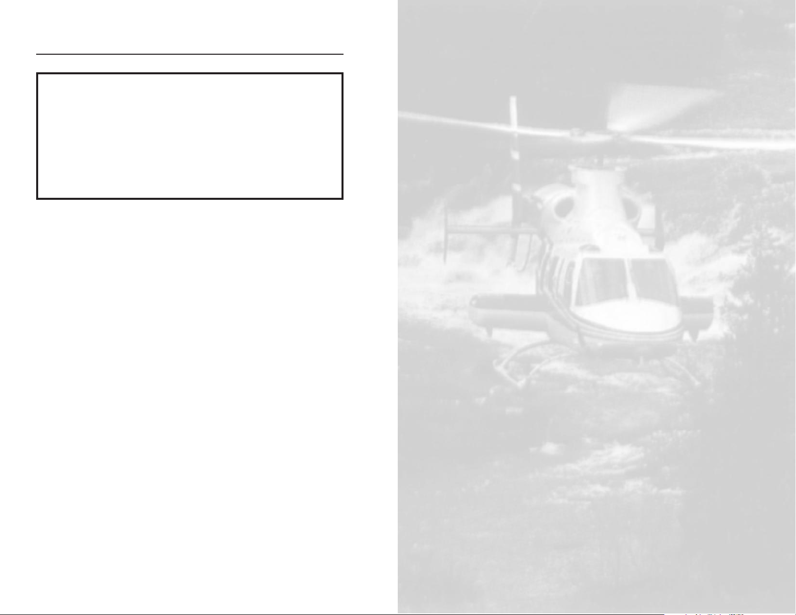
Basic KFC 500 SCAS/Autopilot System Block Diagram
ı
K
C
P 5
2
0
Page 9
Normal Operation
9
006-08769-0000 June 15, 1999
Normal Operation
8
February 15, 1996
006-08769-0000
AFCS GROUND TEST
This momentary switch is used to initiate the SCAS/AP System preflight
test, if desired, after the initial test
that occurs at system power up.
Preflight test must be run prior to
attempting system engagement.
SCAS/AP engagement will be disallowed in any axis that has not successfully passed preflight test. The
system will allow engagement and
use of any available axis (roll, pitch,
and/or yaw) that has passed.
SCAS & AP PWR/OFF
Depressing the SCAS & AP
PWR/OFF switch will turn power on
or off to the SCAS/AP system.
Power is available to the system
when the OFF annunciation is not
illuminated.
Basic SCAS/AP
Operation
This section provides the Normal
Operating Procedures for the basic
SCAS/AP version of the KFC 500
System.
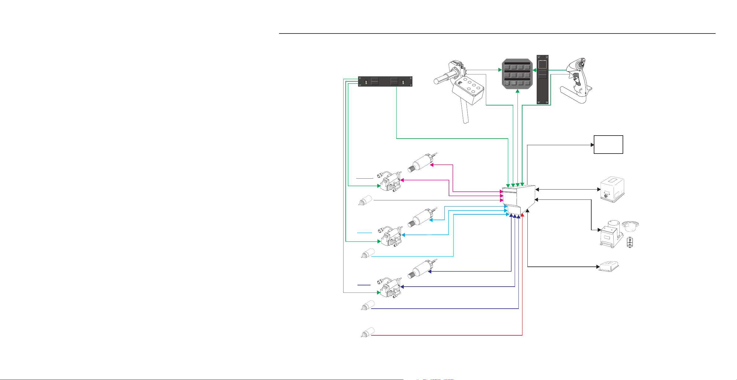
SCAS/AP Remote Switches
There are three remote switches for
the system. They are located in the
pedestal, one just above, and two to
the right of the AFCS Mode Select
Panel.
Force Trim/OFF
Depressing the FORCE TRIM/OFF
switch will turn power on or off to the
Force Trim system. Power is available and the system is on when the
OFF annunciation is not illuminated.
RADIO
ICS
FOOT
SW
RADIO
ICS
FOOT
SW
FORCE
TRIM
OFF
AP ON
SCAS ON
FORCE
TRIM
OFF
AFCS
GROUND
TEST
SCAS &
AP PWR
OFF
SCAS &
AP PWR
FORCE
TRIM
TEST/BRT/DIM (AFCS LAMP
TEST)
Moving the TEST/BRT/DIM Switch,
located on the overhead panel below
the Emergency Bus 1 Breakers, to
the test position will invoke an AFCS
test function that will turn on the
annunciators in the KMS 541 Mode
Select Panel. These annunciations
shall remain on as long as the switch
is held in test position up to a maximum of 15 seconds. This lamp test
function can be invoked any time
desired by the pilot and has no effect
on mode operation. An automatic
lamp test function is performed upon
power up of the Mode Select Panel
and will turn on all MSP annunciators for approximately 2 seconds
immediately after power is applied.
These annunciators may also be
turned on by a special test bit from
the FCC during part of its preflight
testing. See Bell Helicopter 430
Flight Manual for other functions
activated by this switch in the test
position.
TEST
DIM
B
R
T
Page 10
Normal Operation
10
June 15, 1999
006-08769-0000
Normal Operation
11
006-08769-0000 June 15, 1999
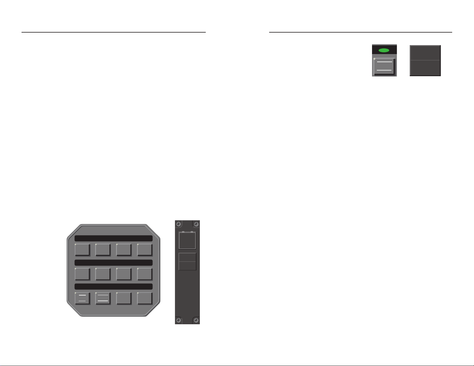
Modes of Operation
The KMS 541 Mode Select Panel
provides control and annunciation of
the KFC 500’s SCAS and AP (attitude retention) modes. To activate
the SCAS or AP modes using the
Mode Select Panel, press the
desired push-button. The corresponding mode lamp will illuminate
above the switch. Alternatively, to
deactivate the SCAS or AP mode
when activated, depress the respective push-button and then release
(The AP mode reverts to SCAS
when deselected).
There is a remote repeater annunciator located above the mode selector panel. This annunciator will mimic
the annunciators located above the
mode switches on the Mode Select
Panel. The brightness of the annunciator lamps on the mode controller
is adjusted automatically by a photocell located on the face of the unit.
The button nomenclature back lighting is controlled by the pedestal dimmer control on the overhead panel.
SCAS Mode
Depressing the SCAS button on the
Mode Select Panel will activate the
stability augmentation mode. The
annunciator above the switch on the
MSP and above the MSP on separate panel will illuminate to verify that
the flight computer has recognized
the button push.
The SCAS (Stability Control
Augmentation System) mode provides rate damping. It may be
referred to as a damper system that
is stabilizing the helicopter against
outside disturbances and thereby is
augmenting the pilot effort. The
SCAS mode is designed so that pilot
control inputs which cause helicopter
attitude changes are not significantly
counteracted by the stability augmentation system. Only helicopter
motions caused by outside disturbances are counteracted. Some
amount of SCAS counteraction is
designed into the system for better
pilot feel in the Bell 430.
AP Mode
The autopilot (AP) push-button
engages the pitch, roll, and yaw
axes and provides trim follow-up for
those axes. Depressing the AP button on the Mode Select Panel will
activate this mode. The annunciator
above the switch on the MSP and
above the MSP on separate panel
will illuminate to verify that the flight
computer has recognized the button
push. The Force Trim system must
be on for this mode to operate.
SCAS/AP Annunciators
There are nine annunciators for the
system available on the IIDS
(Integrated Instrument Display
System), AFCS DISC (red), 1 SCAS
and SCAS 2 (yellow), 1 AP and AP 2
(yellow), AFCS PIT (yellow), AFCS
ROL (yellow), AFCS YAW (yellow),
and AUTOTRIM (yellow). The SCAS
(1)/(2) and AP (1)/(2) failure annunciators will be illuminated any time
prior to preflight test being performed, after a major system failure
has been detected or if SCAS/AP
PWR is OFF. Single axis failures will
not cause the SCAS (yellow) or AP
(yellow) annunciation’s to light on the
selected system. You will get an axis
failure only (i.e. AFCS PIT). A roll or
pitch axis failure indicates that control of that axis has been lost. A yaw
axis failure indication means that
yaw axis or trim follow up in yaw axis
is lost. If it is only a yaw trim axis
failure the annunciator will extinguish
if SCAS engaged. An Autotrim failure indication means that roll or pitch
trim has failed and more attention
will need to be given to see that the
system is kept within the control
authority of the main servo by using
the FTR switch to keep the system
working within its control range. The
non-selected system will annunciate
AP and SCAS Fail annunciation for
single axis failures in roll, pitch
and/or Rate Gyro failure. The nonselected system will annunciate AP
Fail for pitch and roll trim axis failure
and / or when vertical acceleration is
invalid or Vertical Gyro is invalid
after normal power up delay. If this
side is selected then the annunciation will display the single or multiple
axis failures applicable and clear the
AP and / or SCAS Fail annunciation
if any axis is available for use.
ı
AP
SCAS
KMS 541 SCAS/AP Mode Select Panel
AFCS
GROUND
TEST
SCAS &
AP PWR
OFF
SCAS
SCAS ON
Page 11
Normal Operation
12
June 15, 1999
006-08769-0000
Normal Operation
13
006-08769-0000 June 15, 1999
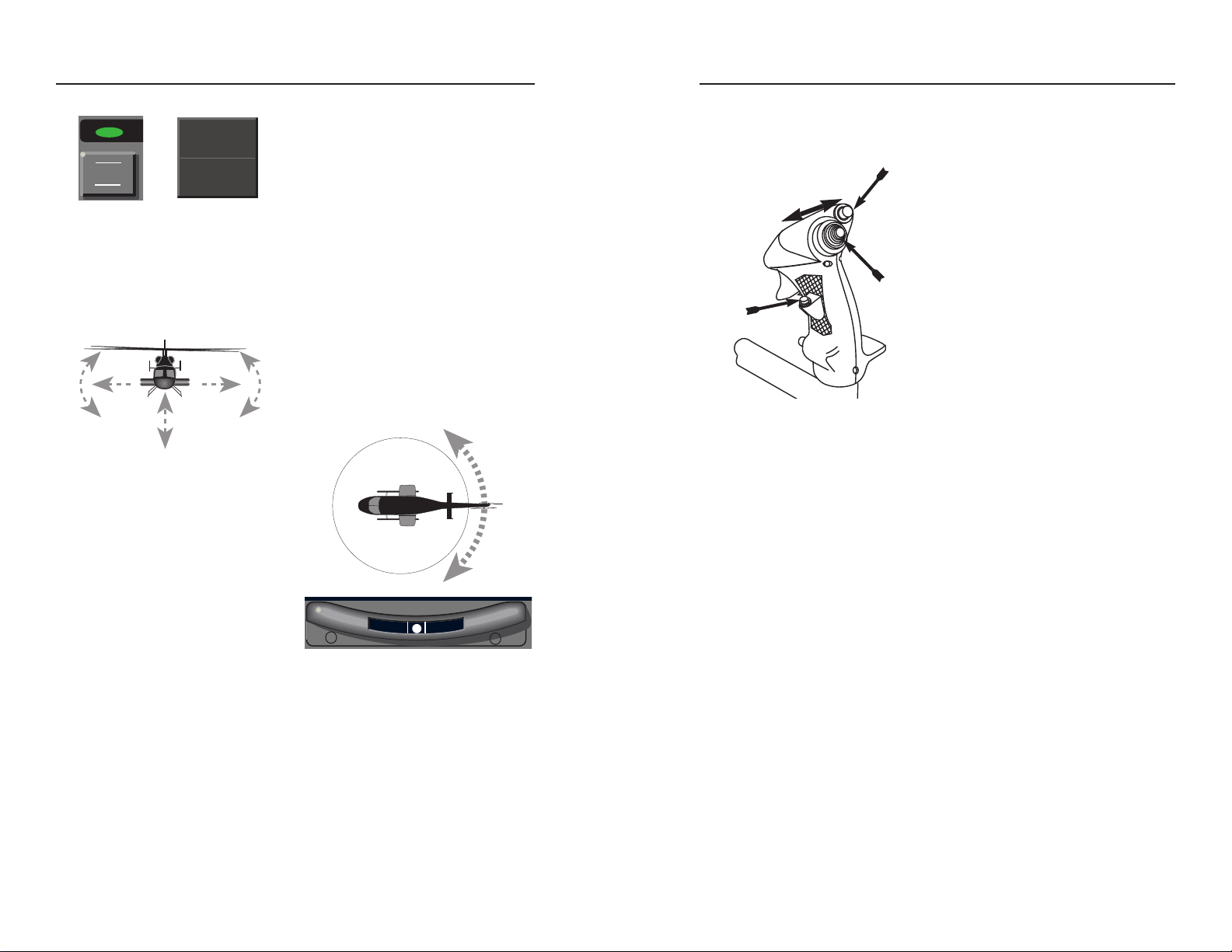
Lateral Command Control
Activated by the Cyclic Beep Trim
(CBT) switch when the AP mode is
on, Lateral Command Control modifies the autopilot’s reference roll attitude. When Lateral Command
Control is used, the aircraft will be
commanded to follow the pilot’s or
copilot’s input to roll left or roll right. If
the switch is given a discrete push
the first click will yield 6° of bank and
1° per click thereafter. If the switch is
pressed continuously the system will
command a constant roll rate until
the beep trim switch is released.
Upon release of the CBT switch, the
autopilot will command the aircraft to
maintain the existing roll attitude.
Roll attitudes of less than six
degrees of bank will cause the
autopilot to revert to commands for
roll-level with heading hold.
Autopilot mode will provide commands to maintain the current pitch
attitude and heading. If the roll attitude is not level upon AP engagement, the autopilot will command a
level attitude and maintain the heading at the time the aircraft rolls level.
Desired roll and pitch attitudes may
be selected by several methods.
Adjusting the helicopter’s attitude
manually may be accomplished by
pressing the Force Trim Release
(FTR) switch (on the cyclic) to the
first detent while moving the cyclic
(and the helicopter to the desired
attitude). Upon release of the FTR,
the autopilot will provide commands
to maintain the target pitch and roll
attitude if greater than 6°. If the roll
attitude is less than 6° the system
will return to roll level and hold the
existing heading. The pilot may manually fly the aircraft to a new attitude,
press and release the FTR switch,
and release the cyclic (Fly Through
mode). When the system senses
pilot fly through (detents made in
force feel springs) the system will
revert to SCAS. The system will
return to AP (attitude hold) after the
FTR switch is released. The system
will hold the existing pitch attitude
reference existing at the time of
release and will return to roll
level/heading hold. The pilot may
momentarily fly the aircraft manually
at any time. After release of the
cyclic the autopilot will return to attitude hold (AP annunciated), and fly
the aircraft back to the attitude existing at the time that the pilot intervened. Alternatively, attitude hold
commands may be modified by moving the Cyclic mounted Beep Trim
(CBT) switch in the appropriate
directions.
The yaw axis augments rotorcraft
stability by opposing uncommanded
yaw motion and providing ball centering. Loss of #1 hydraulic system
automatically disconnects the flight
control system from the yaw axis. In
case of #1 hydraulic power loss, consult the Rotorcraft Flight Manual for
the procedures specified for AFCS
yaw axis operation.
AFCS DISC
CYCLIC GRIP SWITCHES
CBT
FTR
AP
AP ON
Page 12
Normal Operation
14
February 15, 1996
006-08769-0000
Normal Operation
15
006-08769-0000 February 15, 1996
Activating Discrete or Continuous Lateral Command has the following effect
upon the command reference for autopilot operation:
SCAS/Autopilot Disconnect
The cyclic mounted AFCS DISC
switch when pushed disconnects AP
and/or SCAS mode if engaged. This
switch provides the pilot or copilot a
quick and easy means to disconnect
either of these two control coupled
modes.
Force Trim Release (FTR)
The FTR switch is a double detent
switch. Actuation to the first detent
allows the pitch and roll clutches to
release for free cyclic movement.
Depressing through the second
detent releases the yaw clutch in
addition to the pitch and roll, allowing
free cyclic and anti-torque pedal
movement.Pushing and releasing
the FTR switch when the autopilot
mode is on (attitude hold), causes
the system to synchronize its reference attitude with the present helicopter attitude.
When the FTR switch is pressed, the
AFCS will revert to SCAS (when AP
is engaged) and the trim servo magnetic clutches release eliminating the
artificial feel system and allowing
the pilot or copilot free movement of
the cyclic. When the switch is
released the AP and trim clutch reengages. The Force Trim System
must be on for the AP mode to operate.
Yaw Force Trim Release
A collective mounted Yaw Force
Trim Release is provided. If the
Force Trim System is on, depressing
this switch releases the yaw clutch
(AFCS yaw axis will revert to SCAS
if engaged), allowing free anti-torque
pedal movement. The AFCS will
annunciate SCAS under this condition until the yaw force trim release is
released.
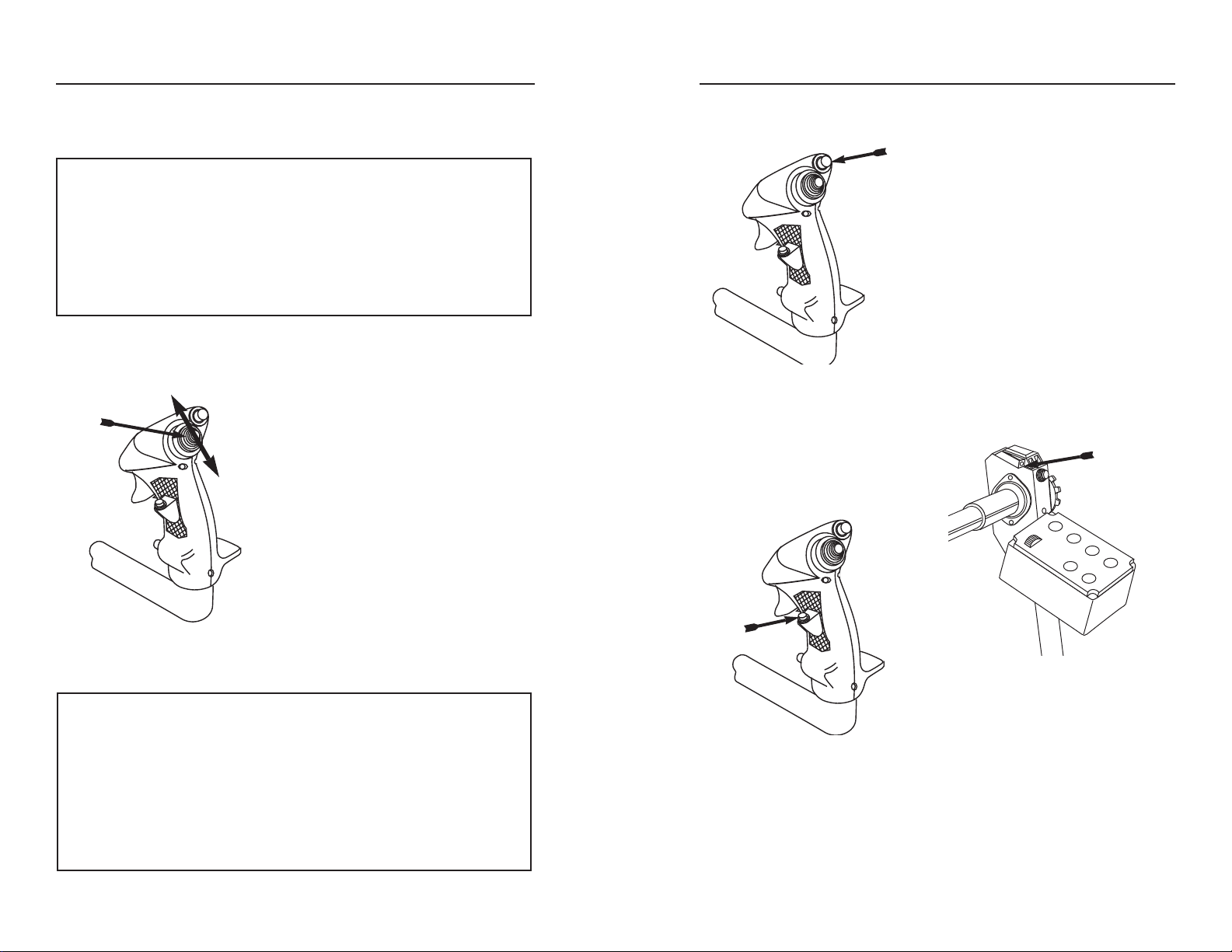
Pitch Command Control
Using the same cyclic beep switch
as mentioned in the previous paragraph, the autopilot’s reference pitch
attitude can be modified by moving
the pitch command switch fore or aft.
Moving the switch forward adjusts
the helicopter’s pitch attitude downward, while moving it aft adjusts the
attitude upward.
Activating Discrete or Continuous Pitch Command has the following effect
upon the command reference for autopilot operation:
Autopilot Lateral Command Values
Discrete Command System Response
Roll Attitude First Click=6°, Subsequent=1° per click
Continuous Command
Roll Attitude Constant Roll Rate
Autopilot Pitch Command Values
Discrete Command System Response
Pitch Attitude 0.5° per click
Continuous Command
Pitch Attitude Maintains constant. acceleration profile
until release
CBT
AFCS DISC
FTR
YAW
FORCE
TRIM
RELEASE
Page 13
17
KFC 500
Flight Director
Normal Operation
006-08769-0000 February 15, 1996
Normal Operation
16
February 15, 1996
006-08769-0000
This page intentionally left blank.
Page 14
This page intentionally left blank.
18
006-08769-0000
February 15, 1996
19
Normal Operation
006-08769-0000 February 15, 1996
1
K
D
C
4
8
1
0
2
3
4
5
6
7
8
9
ALT
VS ALT
1000 FT/MIN
VS
2
3
21
1
.5
.5
0
UP
DN
IN HG HPa
DEN ALT
SEL
VS
1,160
30.08 1,700
1
ENG SEL
ı
BARO
U
P
S
H
E
T
S
T
SEL
U
P
L
L
V
S
3
ALT
ALERT
ı
APRHDG
ALT
BL
IAS
AP
FD
NAV
VS
SCAS
KCP 520
AFCS
Computer
KMS 540
Mode Selector
Trim Actuator
Linear Actuator
Control Position
Synchro
Cyclic
Switches
PITCH
ROLL
YAW
Collective
Switches
IIDS
Control Position
Synchro
Control Position
Synchro
Collective Control Position Synchro
Trim Actuator
Linear Actuator
Trim Actuator
Linear Actuator
Display
System
Navigation
Receivers
SCAS/AP Remote Switches
KRG 333 Rate/Acceleration Sensor
KCS 305 Compass #2
KVG 350 VG #2
MANCWAUTO
CCW
-
+
K
S
G
1
0
5
1
KDC 481T Air Data Computer
KAV 485
Altimeter/
VSI
D
I
R
E
C
T
I
O
N
O
F F
LIGH
T
RADIO
RADIO
ICS
FOOT
SW
RADIO
ICS
FOOT
SW
PIC
R
FORCE
TRIM
OFF
AP ON
SCAS ON
AFCS
GROUND
TEST
SCAS &
AP PWR
OFF
EFIS PWR
PL1
OFF
OFF
EFIS PWR
CPL1
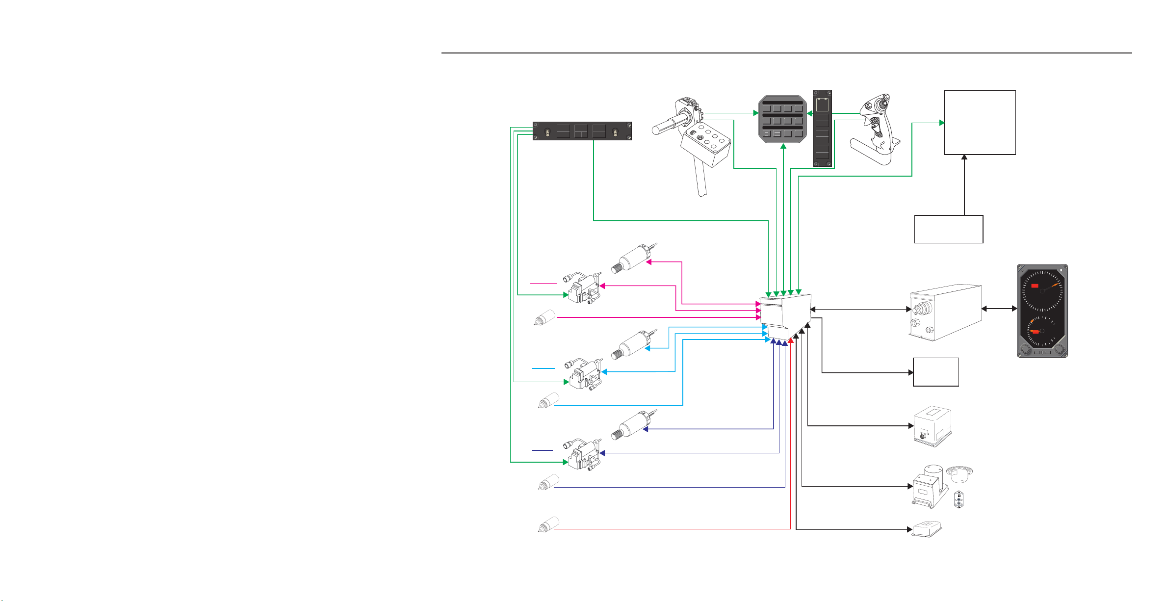
KFC 500 SCAS/Autopilot/Flight Director System Block Diagram
ı
KCP 520
Page 15

Yaw Force Trim Release
A collective mounted Yaw Force
Trim Release is provided. If the
Force Trim System is on, depressing
this switch releases the yaw clutch
(AFCS yaw axis will revert to SCAS
if engaged), allowing free anti-torque
pedal movement. In flight director
equipped aircraft, if the autopilot is
engaged, upon release of the switch
the autopilot will command ball centered flight.
Normal Operation
20
June 15, 1999
006-08769-0000
Normal Operation
21
006-08769-0000 June 15, 1999
Flight Director Operation
Modes of Operation
The KMS 540 Mode Select Panel
provides control and annunciation of
the KFC 500’s Flight Director modes
as well as the Autopilot and SCAS
modes. The Autopilot and SCAS
modes operate the same as previously described in the
SCAS/Autopilot section. To activate
flight director modes using the Mode
Select Panel, press and release the
desired button. The corresponding
mode lamp above the push-button
will illuminate and the mode annunci-
The following section provides an explanation of the normal operating procedures for the flight director functions of the KFC 500 SCAS/AP System when
equipped with Flight Director. SCAS/AP operation is identical to that of the
basic SCAS/AP System, described in the proceeding section, with the following exceptions.
SCAS/AP Operation
(Flight Director installed)
When the Flight Director is included
in the system a central air data system is also installed. The air data
system allows the AFCS to provide
additional functionality in the yaw
axis plus improved performance with
airspeed gain scheduling. The yaw
axis, as described in the previous
section, augments rotorcraft stability
by opposing uncommanded yaw
motion (rate damping - keeps nose
from moving) and ball centering.
With an air data system installed,
the yaw axis also provides turn coordination and yaw trim (using lateral
acceleration). Lateral acceleration is
used by the system to provide the
described functionality anytime that
the acceleration sensor is valid, the
AFCS is receiving valid airspeed
information from the air data, and the
aircraft is flying at an indicated airspeed greater than 50 knots. When
the aircraft is flying below 50 KIAS,
lateral acceleration is inhibited.
During this time the AFCS yaw axis
will provide yaw rate damping only.
ı
APRHDG
ALT
BL
IAS
AP
FD
NAV
VS
SCAS
KMS 540 Flight Director Mode Select Panel
ation on the Electronic Attitude
Indicator (EADI) will appear.
Alternatively, to deactivate a flight
director mode when activated,
depress and release the respective
push-button. The illumination level of
the annunciator lamps on the mode
selector is adjusted automatically by
a photocell located on the face of the
unit. The button nomenclature back
lighting is controlled by the pedestal
dimmer control on the overhead
panel.
AFCS
GROUND
TEST
SCAS &
AP PWR
OFF
EFIS PWR
PL1
OFF
EFIS PWR
CPL1
OFF
YAW
FORCE
TRIM
RELEASE
Page 16

Normal Operation
22
June 15, 1999
006-08769-0000
Normal Operation
23
006-08769-0000 February 15, 1996
If the Bell 430 is equipped with copilot EFIS, a Pilot in Command (PIC)
switch will be located above the KMS
540 Mode Select Panel. This switch
determines which pilot is in control of
the KFC 500 flight director. L (left) or
R (right) will be lit depending on
which position the switch is in.The
KFC 500 will engage in only one horizontal and one vertical tracking
mode at a time. Flight Director armed
modes do not conflict with active
(capture or track) modes. For example, selecting a new course in the
NAV ARM mode, or a new altitude in
Altitude Select, does not affect active
tracking modes such as Heading or
Vertical Speed Hold. It is often useful
to engage a separate mode to provide flight guidance to the capture
point for a course or altitude preselected in an Arm mode. The Flight
Director System will transition automatically to capture the armed mode,
canceling the previous selected
mode. Examples of this operation
are described in the Operational
Examples section of this Pilot’s
Guide.
To cancel a flight director mode
engaged in either capture or tracking
operations, either select an alternate
tracking mode or press and release
the engaged mode’s push-button on
the mode select panel. The latter
method also cancels modes while in
their Arm phases. Go Around is an
exception. The collective mounted
push-button provides the engage
function only. To disconnect Go
Around select another pitch mode.
The Flight Director provides the
basic modes - Roll Attitude
level/Heading Hold and Pitch
Attitude Hold. These default modes
provide basic flight stability and
serve as safety backups in the event
that the flight director cancels an
active mode due to loss of a required
navigation signal or sensor failure.
Engaging the KFC 500 in any tracking mode automatically cancels the
corresponding default mode for that
particular axis.
Pitch Attitude Hold & Roll
Attitude Hold (FD)
In the absence of any other selected
Flight Director modes, the system
will provide commands to maintain
current pitch attitude and establish a
level roll attitude. When roll attitude
approaches six degrees or less bank
angle, the flight director will provide
commands to maintain constant
heading.
Desired roll and pitch attitudes may
be selected by several methods. If
the Flight Director is coupled to the
autopilot (AP ON), the helicopter’s
attitude may be manually adjusted
by pressing the Force Trim Release
(FTR) switch to the first detent while
moving the cyclic (and helicopter) to
the desired attitude. Upon release of
the FTR switch, the Flight Director
will provide commands to maintain
the new target Pitch and Roll attitude
(or Heading). Alternatively, Attitude
Hold commands may be modified by
moving the cyclic mounted Cyclic
Beep Trim (CBT) switch in the
appropriate directions
If a target roll attitude of six degrees
or less is selected, the Flight Director
will provide commands to maintain
the helicopter’s current heading.
Selecting any horizontal or vertical
tracking mode cancels Roll
Attitude/Heading Hold or Pitch
Attitude Hold, respectively. Either
mode may be used in conjunction
with any Arm mode to provide flight
guidance for course or altitude intercepts. Pressing the FD switch without any FD modes engaged will
engage the basic default modes.
Pressing FD when any modes are
engaged will disengage all Flight
Director modes. Pressing FD when
AP engaged will disconnect all FD
modes and revert to basic AP
Attitude Hold modes.
Lateral Command Control
Activated by the Cyclic Beep Trim
(CBT) switch when the Flight
Director is on, Lateral Command
Control modifies the system’s reference attitude during operations in
Roll Attitude Hold. Operating Lateral
Command Control does not affect
Capture/Track in Navigation (NAV)
mode or Capture/Track in Approach
(APR) mode. To operate Lateral
Command Control with Navigation or
Approach mode in track, the mode
must first be deselected by pushing
the button on the Mode Select Panel.
When the system mode is roll level
or bank angle hold (FD and/or AP)
and the Lateral Command Control is
used, the aircraft will be commanded
to follow the pilot’s input to roll left or
right. If the switch is held continuously the system will command a
constant roll rate until the beep trim
switch is released. If the switch is
pushed discretely, the first push will
yield 6° of bank and 1° of bank for
each additional push or click.
Upon release of the CBT switch, the
flight director will command the aircraft to maintain the existing roll attitude. Roll attitudes of less than six
degrees of bank will cause the Flight
Director to revert to commands for
roll-level flight with heading hold.
The heading bug on the EHSI may
be slewed to a new heading using
the CBT switch. With heading select
(HDG) mode engaged, move the
CBT switch to the left or right to reposition the heading bug.
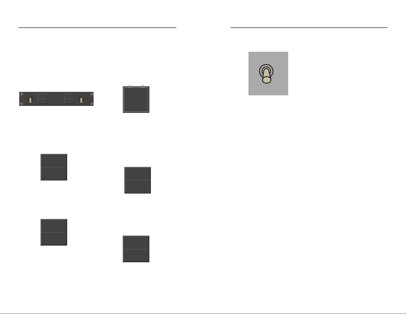
FD
☛
AFCS DISC
FD OFF
CYCLIC GRIP SWITCHES
CBT
FTR
PIC
L R
Page 17

Normal Operation
24
February 15, 1996
006-08769-0000
Normal Operation
25
006-08769-0000 June 15, 1999
Activating Discrete or Continuous Lateral Command has the following effect
upon command values in flight director operations:
Vertical Command Control
Using the same cyclic switch as
mentioned in the previous paragraph, vertical commands can be
modified by moving the CBT switch
fore or aft. Operation of the Vertical
Command Control depends on the
flight director mode engaged.
Moving the switch forward adjusts
the helicopter’s pitch attitude downward, while moving it aft (rearward)
adjusts the attitude upward.
Activating Vertical Command has the
following effect on flight director vertical modes: has no effect on ALT
ARM (altitude preselect arm), ALTC
(altitude capture), GS (glideslope),
GA (go around), overspeed protection (nose down or “increasing airspeed”), and autolevel. To use
Vertical Command Control when
these modes are engaged, first deselect the mode. Vertical Command
will trim or modify the reference for
PIT (pitch attitude hold), ALT (alti-
Force Trim Release (FTR)
When the Flight Director is active,
and coupled to the autopilot (AP
ON), the Force Trim Release switch
allows the crew to synchronize flight
director commands in pitch and roll
to the actual helicopter position.
When the selected mode for flight
director is pitch attitude hold, altitude
hold, airspeed hold, vertical speed
hold, roll level/heading hold, or roll
attitude hold, pushing FTR will cause
a new flight director reference to be
established upon release of the
switch. All commands will then be
directed to hold this new reference. If
the AFCS is in APR mode and GS
track, pressing the FTR will have no
effect. If the AFCS has reverted to
overspeed protection mode, the FTR
switch is pushed and held, and the
pilot manually reduces airspeed to a
value below VNE, upon FTR release
the system will revert to the previously engaged pitch mode. Pressing
the FTR switch will have no effect on
ALT ARM, ALT capture, Go Around,
Autolevel, HDG select, NAV or APR
modes including GS. Upon release
of the FTR switch, the flight director
will provide commands to return to
the above modes.
Flight Director Lateral Command Values
Discrete Command System Response
Roll Attitude Hold First Click=6°, Subsequent=1° per click
Heading Select 1° Heading Bug novement per click
Continuous Command
Roll Attitude Hold Constant Roll Rate
Heading Select 16° Heading Bug movement per second
Flight Director Vertical Command Values
Discrete Command System Response
Pitch Attitude 0.5° per click
Altitude Hold 10 feet per click
Indicated Airspeed Hold 1 Knot per Click
Vertical Speed Hold 100 feet per minute per click
Continuous Command
Pitch Attitude Maintains constant. acceleration profile
until release
Altitude Hold 50 feet per second until release
Indicated Airspeed Hold 5 knots per second until release
Vertical Speed Hold 300 feet per minute per second until
release
tude hold), VS (vertical speed hold),
IAS (indicated airspeed hold) and
overspeed protection (nose up or
“decreasing airspeed”). Attitude
Hold, Altitude Hold, Indicated
Airspeed Hold, and Vertical Speed
Hold will remain coupled throughout
Vertical Command (CBT) operation.
Activating Discrete or Continuous Vertical Command Control has the following
effect upon command values in flight director operations:
CBT
FTR
Page 18

Normal Operation
26
February 15, 1996
006-08769-0000
Normal Operation
27
006-08769-0000 June 15, 1999
Flight Director Off
When the Flight Director Off (FD
OFF) switch on the cyclic is momentarily depressed, the flight director
de-activates and the system reverts
to roll level/heading hold and pitch
attitude hold if the autopilot was previously engaged. Subsequent activation of the flight director modes may
be accomplished by depressing the
appropriate Mode Select Panel push
buttons or by arming altitude select
or engaging vertical speed hold from
the Altitude/Vertical Speed Indicator.
Go Around
Pressing the GO AROUND push
button on the collective switch box
activates the Go Around mode in
which the flight director commands a
750 feet per minute climb and a roll
level attitude. Any horizontal tracking
mode may be subsequently reengaged without canceling the Go
Around mode.
Go Around mode can only be canceled by selecting another vertical
mode (i.e. ALT, IAS, or VS).
Heading Select (HDG)
Depressing the HDG push-button on
the mode select panel activates
Heading Select mode. This mode
will provide flight director commands
to track the heading bug on the
EHSI. The annunciator above the
switch on the mode select panel illuminates and “HDG” is displayed, in
green, on the EADI when the heading select mode is activated.
Activating heading select cancels
any other lateral tracking mode. If
the heading select mode is active,
depressing the HDG push-button will
deactivate the mode and revert the
flight director back to the default
mode of roll level and heading hold.
Upon manual deactivation, the
annunciator lamp above the HDG
push-button and the green HDG
annunciation on the EADI will flash
for five seconds. This flash
sequence will terminate upon reactivation of HDG or another lateral
mode. Continuous flashing of the
annunciator lamp above the pushbutton and the flashing of and
changing color from green to yellow
of the HDG annunciation on the
EADI indicates loss of a sensor
required to hold the selected heading (e.g. invalid magnetic heading,
invalid selected heading from EHSI).
The annunciations will continue
flashing until the HDG push-button is
activated (pilot acknowledgment of
mode loss) or another lateral mode
is selected.
Bank Angle Limit (BL)
The Bank Angle Limit mode allows
the maximum commanded bank
angle to be selected by the pilot. The
default value, 20°, is obtained at
power-up. The pilot may select 15°,
10°, 25° and then 20° again by
pressing the BL button until the
desired maximum bank is achieved.
The selected maximum bank angle
is annunciated on the EADI as BL15,
BL10, or BL25. The default value of
20° is not annunciated. In the
approach phases of flight, bank
angle limiting is disabled to provide
optimized approach guidance by the
flight director. All approach captures
are made with a maximum bank
angle of 20°. If lesser bank angles
are desired, the pilot may use the
heading select mode (move the
heading bug slowly) to capture the
localizer and then depress the APR
push-button to activate Approach
mode when tracking inbound on the
appropriate course.
When the flight director is coupled to
a long range navigation sensor like a
navigation management system
(NMS), GPS, etc. (i.e. GNS-X, KLN
90) that has a composite steering
output, the long range navigation
sensor has complete control of bank
Autopilot/Flight Director Mode Annunciation
AP
HDG IASNAV ALT
120 KT
20 20
BL25 GS
FD
1. Bank Angle Limit
2.Autopilot Engaged Annunciator
3. Armed Lateral Mode
4. Active Lateral Mode
5. Command Reference Value
6. Active Vertical Mode
7. Armed Vertical Mode
8. Flight Director Flag
KMS 540 Flight Director Mode Selection
HDG
☛
☛
FD OFF
GO
AROUND
1
32 4 5 6 7
7
8
BL
Page 19

Normal Operation
28
June 15, 1999
006-08769-0000
Normal Operation
29
006-08769-0000 June 15, 1999
angles up to 25° unless a bank limit
is selected. Bank limiting is allowed
in this situation and can affect tracking performance. If improved Long
Range NAV tracking is desired, set
the bank limit to the default value
(20°).
Navigation Mode (NAV)
The NAV lamp illuminates and
“NAV” is displayed on the EADI
when the NAV mode is activated by
depressing the NAV push-button on
the KMS 540 Mode Select Panel.
When the NAV mode is selected by
the NAV push-button and course
needle deflection is greater than
50% full scale needle deviation, the
NAV ARM (NAV white on EADI)
mode is activated and allows a compatible lateral mode to be used to
intercept the desired course or track.
If the aircraft’s deviation from the
selected course centerline is less
than 50% full scale needle deviation,
or if the rate of closure with the new
course is sufficiently high, the flight
director initiates the NAV capture
(NAV green on EADI) sequence
immediately. If the NAV mode is
active, depressing the NAV pushbutton will deactivate the mode and
revert the flight director back to the
default mode of roll level and heading hold. Upon manual deactivation,
the annunciator lamp above the NAV
push-button and the green NAV
annunciation on the EADI will flash
for five seconds. This flash
sequence will terminate upon reactivation of NAV or another lateral
mode.
Continuous flashing of the annunciator lamp above the push-button and
the flashing of and changing color
from green to yellow of the NAV
annunciation on the EADI indicates
loss of a sensor required to capture
or track the selected navigation sensor (e.g. invalid navigation receiver,
invalid selected course from EHSI).
The annunciator continues to flash
until the NAV push-button is pushed
(pilot acknowledgment of mode loss)
or another lateral mode is selected.
Approach Mode (APR)
The APR lamp illuminates and
“APR” is displayed on the EADI
when the APR mode is activated by
depressing the APR push-button on
the KMS 540 Mode Select Panel.
When the APR mode is selected by
the APR push-button and course
needle deflection is greater than
50% full scale needle deviation, the
APR ARM (APR white on EADI)
mode is activated and allows a compatible lateral mode to be used to
intercept the desired course or track.
If the aircraft’s deviation from the
selected course centerline is less
than 50% full scale needle deviation,
or if the rate of closure with the new
course is sufficiently high, the flight
director initiates the APR capture
(APR green on EADI) sequence
immediately. If the APR mode is
active, depressing the APR pushbutton will deactivate the mode and
revert the flight director back to the
default mode of roll level and heading hold. Upon manual deactivation,
the annunciator lamp above the APR
push-button and the green APR
annunciation on the EADI will flash
for five seconds. This flash
sequence will terminate upon reactivation of APR or another lateral
mode.
The flight director may initiate
turn commands before the course
deviation indicator displays movement.
Selecting the Approach mode after
the aircraft has already passed the
point at which Approach Capture
normally would begin may result initially in course overshoot due to the
flight director’s roll command limits.
The KFC 500 discriminates automatically between LOC, LOC back
course, VOR, LNAV, and GPS sensor types. The KFC 500 uses the
sensor type information to determine
if BC (back course) is an appropriate
mode; after that front course/back
course selections are determined by
the relative angle between the aircraft’s heading and the course
selected on the EHSI. Intercept
angles between 0° and 105° cause
the KFC 500 to select front course
(LOC is selected sensor on EHSI).
Angles between 106° and 180°
cause the flight director to command
back course interception and tracking (LOC selected sensor on EHSI).
It is essential that the course
selector arrow on the EHSI display always
be aligned with the
ILS front course. When flying
inbound on a Backcourse
Approach, the selected course
should be in the opposite direction of the helicopter’s heading.
Failure to align the course arrow
properly will result in erroneous
front/back course selection by the
flight director.
The flight director automatically
engages Glideslope Arm (GS white
on EADI), Capture and Track (GS
green on EADI) sequences during
ILS front course approaches. The
localizer must be captured in order
for glideslope to ARM and then couple. Glideslope coupling is inhibited
during back course procedures.
Any horizontal tracking mode may
be employed during Approach Arm
phases and will cancel automatically
upon initiation of Approach Capture
and Track. Any vertical mode may
be used prior to glideslope capture
or track and will automatically cancel
upon initiation of glideslope capture.
Activation of Approach Capture will
automatically incorporate the default
maximum commanded bank angle,
20°, for optimum performance.
Continuous flashing of the annunciator lamp above the push-button and
the flashing of and changing color
from green to yellow of the APR (i.e.
VOR source) or LOC/GS (i.e. ILS
source) annunciation on the EADI
indicates loss of a sensor required to
capture or track the selected navigation sensor (e.g. invalid navigation
NAV
☛
☛
APR
Page 20

Normal Operation
30
June 15, 1999
006-08769-0000
Normal Operation
31
006-08769-0000 June 15, 1999
Altitude Hold (ALT)
The light above the ALT push-button
illuminates and “ALT” is displayed on
the EADI in green when the Altitude
Hold mode is activated by depressing the ALT push-button on the
mode select panel or by automatically sequencing through Altitude
Arm and Altitude Capture via the
KAV 485. In the Altitude Hold mode,
the flight director commands pitch
attitudes for tracking of the helicopter
altitude at the moment of mode
selection. The system normally uses
barometrically corrected altitude, but
can use pressure altitude in the
event barometric altitude is not available. Altitude Hold mode also
requires valid vertical acceleration
from the KRG 333. Altitude Hold can
be entered directly or in conjunction
with the Altitude Select mode.
Engaging Altitude Hold directly during a climb or descent will cause the
aircraft to fly through the desired altitude and then return to the desired
altitude from the other side. For this
reason, the vertical speed should be
limited to 500 fpm when this method
of Altitude Hold engagement is used.
Selecting Altitude Hold after the
Altitude Select mode has been
engaged does not cancel Altitude
Arm indication (white “ALT” on
EADI). The flight director will com-
mand the aircraft to hold the altitude
present at the moment of mode
selection.
The commanded altitude hold reference value is displayed on the EADI.
This value may be modified by moving the CBT switch forward
(decrease reference altitude) or rearward (increase reference altitude).
The pilot may also press the FTR
switch and manually fly the aircraft to
a new altitude. The AFCS will hold
the new altitude reference existing at
the time of release of the FTR
switch.
Continuous flashing of the annunciator lamp above the push-button and
the flashing of and changing color
from green to yellow of the ALT
annunciation on the EADI indicates
loss of a valid altitude signal from the
air data computer or loss of valid vertical acceleration. The flashing continues until the pilot pushes and
releases the ALT push-button on the
mode select panel (acknowledges
loss of the mode) or selects another
pitch mode. The ALT push-button on
the mode select panel may be used
to cancel the Altitude Hold mode at
any time. Upon manual deactivation,
the annunciator lamp above the ALT
push-button and the green ALT
annunciation on the EADI will flash
for five seconds. This flash
sequence will terminate upon reactivation of ALT or another pitch mode.
receiver, invalid selected course from
EHSI). The flashing annunciation
may be extinguished by pressing and
releasing the APR push-button (pilot
acknowledgment) on the mode
select panel. If glideslope invalid
occurs for approximately 30 seconds
during glideslope arm the system will
revert back to the previously
engaged pitch mode. If glideslope
invalid occurs for approximately 5
seconds during the capture or track
phase the system will revert to pitch
attitude hold.
Autolevel Mode
The KFC 500 incorporates a submode called autolevel anytime the
autopilot/flight director system is APR
coupled on an ILS and the Radar
Altimeter is valid. At approximately
100 feet AGL the system will initiate
autolevel. The autopilot will discontinue GS (glideslope) track and automatically intercept and track approximately 50 feet AGL from the radar
altimeter. The system will hold this
radar altitude until disconnected.
Note: The Autolevel Mode is
approved for VFR operation only.
If the runway is not in sight at the
decision height use of the
Autolevel Mode is not approved.
KAV 485 Altitude Select
Altitude Select (ALT SEL)
The Altitude Select mode provides a
method for selecting, capturing, and
tracking another altitude. Altitude
Select will automatically Arm after a
change in the altitude select value.
“ALT” is annunciated in white on the
EADI when the Altitude Select mode
is armed. The selected altitude is displayed in the KAV 485’s selected altitude window. ALT SEL requires use
of PIT, VS, or IAS modes to be used
to transition to the selected altitude.
Upon reaching the altitude capture
point, the selected vertical mode will
cancel, the flight director will engage
Altitude Capture and then Altitude
Hold. Altitude Select must be deactivated to inhibit capture and tracking
of the pre-selected altitude. If the
value of selected altitude is changed
while in altitude capture, the system
reverts to pitch attitude hold mode. In
the event of sustained invalid altitude, ALT SEL mode will deactivate.
To disengage Altitude Select, press
the SEL mode push-button on the
KAV 485. Detailed operation of the
KAV 485 is provided at the end of
this section.
ALT
☛
Selected
Altitude
Display
ı
0
9
1
ALT
ALT
8
7
30.08 1,700
1,160
6
5
ALT
SEL
2
3
4
ALERT
L
U
L
P
SEL
V
S
Page 21

Normal Operation
32
June 15, 1999
006-08769-0000
Normal Operation
33
006-08769-0000 June 15, 1999
Indicated Airspeed Hold
The lamp above the IAS push-button
illuminates when the airspeed hold
mode is activated by depressing the
IAS push-button on the mode select
panel. Engaging the Indicated
Airspeed Hold mode causes the
flight director to command pitch attitudes to maintain the indicated airspeed current upon selection. The
airspeed displayed on the pilot’s or
copilot’s airspeed indicator may not
exactly agree with the value being
used by the AFCS. The airspeed reference is provided by the KDC 481T
central air data computer.
The commanded indicated airspeed
reference value is displayed on the
EADI. This value may be modified by
moving the CBT switch forward
(increase reference airspeed) or
rearward (decrease reference airspeed).
The pilot may also press the FTR
switch and manually fly the aircraft to
a new airspeed. The AFCS will hold
the new airspeed reference existing
at the time of release of the FTR
switch.
Continuous flashing of the annunciator lamp above the push-button and
the flashing of and changing color
from green to yellow of the IAS
annunciation on the EADI indicates
loss of a valid air speed signal from
the air data computer. Flashing continues until the IAS push-button on
the mode selector is pushed and
released (pilot acknowledgment or
mode loss) or another vertical mode
is selected. The IAS push-button
may be used to deactivate the IAS
mode at any time. Upon manual
deactivation, the annunciator lamp
above the IAS push-button and the
green IAS annunciation on the EADI
will flash for five seconds. This flash
sequence will terminate upon reactivation of IAS or another pitch mode.
Overspeed Protection
As a safety feature, the flight director
automatically reverts to Indicated
Airspeed Hold and flashes the IAS
annunciation (amber “IAS” on EADI)
whenever the helicopter exceeds
VNE or the rate of closure with VNE
is excessive. The flight director will
command pitch attitudes to reduce
indicated airspeed to VNE and then
resume the previous pitch mode.
Overspeed protection is not provided
in Altitude Hold or Altitude Capture
Modes.
Vertical Speed Hold (VS)
Depressing the ENG push-button on
the KAV 485 Altimeter/Vertical
Speed Indicator or the VS button on
the KMS 540 Mode Select Panel
activates the vertical speed hold
mode. In vertical speed mode the
system commands pitch attitudes to
maintain the vertical speed present
at the time of engagement.
The reference vertical speed being
flown is displayed on the EADI in the
AFCS annunciation field and by the
vertical speed bug on the KAV 485
Altitude/Vertical Speed Indicator.
This vertical speed may be modified
by using the CBT switch. Pushing
the CBT switch forward slews the
existing vertical speed reference
towards zero or negative, and pushing aft slews the value towards zero
or positive.
The pilot may also press the FTR
switch and manually fly the aircraft to
a new vertical speed. The AFCS will
hold the new vertical speed reference existing at the time of release
of the FTR switch.
A vertical speed may be preselected via the KAV 485
Altimeter/Vertical Speed Indicator.
Pull out on the vertical speed select
(SEL) knob to reposition the vertical
speed bug and/or bring the bug into
view if vertical speed mode is not
already engaged. Rotate the small
knob to make 100 fpm per click and
the large knob to make 1000 fpm per
click changes to the vertical speed. If
a vertical speed is already preselected at the time of vertical speed
mode engagement, the pre-selected
value will be used immediately by
the AFCS without further action by
the pilot. If the mode is not already
engaged press the ENG push-button
on the altimeter/vertical speed indicator to engage the mode. Push the
select (SEL) knob back in after the
bug position has been modified.
Note: When the select (SEL) knob
is pulled out the knobs modify the
position of the vertical speed bug.
When the knob is pushed in the
knobs modify the selected altitude shown in a digital window on
the indicator.
Continuous flashing of the annunciator lamp above the push-button and
the flashing of and changing color
from green to yellow of the VS
annunciation on the EADI indicates
loss of a valid vertical speed signal
from the air data computer or loss of
valid vertical acceleration from the
KRG 333 Rate/Acceleration Sensor.
Flashing continues until the VS
push-button on the mode select
panel is pushed or another pitch
mode is selected (pilot acknowledgment of mode loss). The VS pushbutton may be used to deactivate
the VS mode at any time. Upon
manual deactivation, the annunciator
lamp above the VS push-button and
the green VS annunciation on the
EADI will flash for five seconds. This
flash sequence will terminate upon
reactivation of VS or another pitch
mode.
KAV 485 Vertical Speed
Select
VS
☛
,
Vertical Speed Bug
IAS
☛
.
IN HG HPa
UP
DN
S
H
U
P
BARO
T
T
E
S
.5
0
VS
.5
VS ALT
ENG SEL
1
VS
1000 FT/MIN
DEN ALT
2
21
SEL
3
3
L
U
L
P
SEL
V
S
Page 22

Normal Operation
34
June 15, 1999
006-08769-0000
Normal Operation
35
006-08769-0000 June 15, 1999
KSA 572 Trim Actuator
The KFC 500 incorporates three trim
actuators (one per axis) in parallel
with the helicopter control linkage.
The trim actuators provide the longterm control guidance by moving the
control system to allow the linear
actuators to center and thus maintain control authority. The trim servo
also houses the magnetic brake portion of the force trim system. The
force trim system also contains a
spring cartridge assembly, in each
axis, which houses a spring and a
sense switch. The spring provides
positive feedback to the pilot or copilot proportional to the amount of control movement. When the pilot or
copilot moves the cyclic or antitorque
pedals the detent (sense) switch will
be activated. If the AP mode is
engaged and the detent switch is
activated the trim actuator drive is
interrupted. If the pilot or copilot
moves the cyclic (pitch and/or roll)
through the detent/s the AFCS will
revert automatically to SCAS (SCAS
annunciator lit). If the pilot or copliot
moves the anti-torque pedals
through the detent the yaw axis will
revert to SCAS operation, but the
pitch and roll axes will remain in AP
mode (SCAS annunciated on Mode
Select Panel and on discrete annunciator). The pilot or copilot may manually fly the aircraft at any time using
this method (Pilot Fly-Through
Mode). Once the pilot or copilot is
ready to allow the autopilot to take
over, the force trim switch may be
pushed and the cyclic and antitorque pedals (if applicable) positioned as desired or release the stick
and pedals and allow the autopilot to
return to its original reference. At
activation of the FTR switch, the
cyclic and the pedals the spring cartridge detent switches will release.
The SCAS mode will automatically
disengage (SCAS annunciator out)
and the AP mode will re-engage (AP
annunciator on). The AFCS will
return to the appropriate reference
for the mode engaged. The AFCS is
designed with absolute attitude limits
and rate limits. During fly through or
other modes of operation , the aircraft attitude/rate must be less than
+ or - 45°/15° per second in roll and
+ or - 15°/10° per second in pitch
and 15° per second in yaw for the
AP mode to remain engaged. If
these limits are exceeded the autopilot will automatically disconnect.
Force Trim and AP Trim
KSM 575 Linear Actuator
Assembly
A KSM 575 Linear Actuator is
installed in pitch, roll and yaw (antitorque) axis of helicopter. The linear
actuator is placed in series with the
control rods to provide limited
authority high speed damping of the
helicopter. The linear actuator contains a position transducer for feedback of actuator position to the Flight
Computer.
KCP 520 Flight Computer
The KCP 520 Flight Computer provides all of the command computation for SCAS, autopilot and flight
director. The KCP 520 houses four
microprocessors. Two (redundant)
Autopilot processors provide the
autopilot control computations and
autopilot/stability augmentation
mode logic, a dedicated processor
for Flight Director provides command
computation and a dedicated
Maintenance processor assists in
diagnostics and maintenance. Inputs
to the Flight Control Computer
include control position feedback
from the control position transducers, and Attitude, Directional, and
Rate information from the vertical,
directional and rate gyros and acceleration from the acceleration sensors. The KCP 520 outputs servo
drive to move the linear and trim
actuators.
AFCS Sensors
KVG 350 Attitude Gyro
The KVG 350 Vertical Gyro provides
attitude information to the EFIS and
the KCP 520 Flight Computer. The
attitude information received by the
Flight Computer is used for computations and system monitoring.
KCS 305 Slaved Compass
System
The KCS 305 Slaved Compass
System is comprised of the KSG 105
Directional Gyro, the KA 51B
Slaving Accessory, and the KMT 112
Flux Valve. The slaved compass system provides magnetic heading information to the EFIS and the Flight
Computer.The Free/Slave switch
provides the pilot a means to manually compensate for magnetic effects
POSITION
SYNCHRO
CYCLIC
FORCE
GRADIENT
SPRING
DETENT
SWITCH
INSIDE
TO
LINEAR
ACTUATOR
TRIM SERVO/
MAG BRAKE
MANCWAUTO
CCW
-
+
KSG 105
1
Flight Control System Components
(SCAS, Autopilot, and Flight Director)
ı
K
C
P
5
2
0
Page 23

Normal Operation
37
006-08769-0000 February 15, 1996
Normal Operation
36
June 15, 1999
006-08769-0000
in the vicinity of the Flux Valve. The
switch allows the pilot to select either
Free or Slaved Magnetic Heading
mode. The slew switch is also utilized for manually correcting heading
information during flight operations
at higher latitudes.
KRG 333 Rate/Acceleration
Sensor
The KRG 333 is a three axis
rate/two axis acceleration sensor
that provides rate and acceleration
inputs to the Flight Computer for
command calculation and monitoring.
Control PositionTransducer
Each control axis (pitch, roll, yaw,
and collective) has a control position
transducer (synchro resolver) to
feedback control position to the
Flight Computer.
KAD 480 Air Data System
The KAD 480 Digital Air Data
System is comprised of the KDC
481T Central Air Data Computer, the
KAV 485 Altimeter/Vertical Speed
Indicator, and a temperature probe.
KDC 481T Air Data Computer
The heart of the KAD 480 Air Data
System, the KDC 481T Central Air
Data Computer, processes pitot and
static pressures and air temperature
inputs, and supplies the processed
information to the KCP 520 Flight
Computer and the KAV 485
Altimeter/Vertical Speed Indicator.
The KDC 481T uses a strap module
which contains aircraft specific information required for overspeed protection, etc. The Central Air Data
Computer is also capable of supplying air data information to optional
Navigation Management Systems.
KAV 485 Altitude/Vertical Speed Indicator
D
I
R
E
C
T
I
O
N
OF FLIGHT
0
2
3
4
5
6
7
8
9
ALT
VS ALT
1000 FT/MIN
VS
2
3
21
1
.5
.5
0
UP
DN
IN HG HPa
DEN ALT
SEL
VS
1,160
30.08 1,700
1
ENG SEL
ı
BARO
U
P
S
H
E
T
S
T
SEL
U
P
L
L
V
S
3
ALT
ALERT
1
2
3
4
5
6
7
8
9
10
11
12 13
1. Hg/HPa Pushbutton
2. Altimeter Flag
3. Altimeter Display
4. Barometric Pressure Setting
5. Vertical Speed Bug
6. Vertical Speed Flag
7. IVSI Diplay
8. Barometric Pressure Setting
Selector/Test
9. Altitude Alert Annunciation
10. Selected Altitude/Density
Altitude
11. Altitude/Vertical Speed
Selector
12. Vertical Speed Engage
Pushbutton
13. Altitude Select Engage
Pushbutton
1
KDC 481
Page 24

Normal Operation
38
February 15, 1996
006-08769-0000
Normal Operation
39
006-08769-0000 February 15, 1996
Altitude Select/Density Altitude Provides continuous display of altitudes selected for altitude alerting
and flight director capture and tracking, or momentary display of current
density altitude derived by the central air data computer. Preselected
altitudes are displayed in 100 foot
increments.
The current density altitude displays
for approximately 5 seconds at the
end of the air data’s preflight test
function. Pressing the PUSH BARO
TEST push-button twice in rapid succession summons the density altitude display at any time.
Altitude/Vertical Speed Preselect
Control - Dual, concentric knobs
control altitude and vertical speed
preselection. To preselect altitude,
press the smaller knob to ensure it is
in the inner position. Rotating the
smaller knob adjusts the preselected
altitude in 100 foot increments, with
automatic roll-over to higher values.
The outer knob adjusts altitude in
1000 foot increments.
Pulling the smaller knob to its outer
position initializes the vertical speed
bug (5), synchronizing it with the last
vertical selected and references the
control knob to vertical speed. The
smaller knob adjusts selections in
100 fpm increments, with automatic
roll-over. The larger knob adjusts
selections in 1000 fpm increments.
Altitude Alert - Illuminates when the
aircraft’s current altitude is within 300
- 1000 feet of the value specified in
the altitude preselect display. Upon
reaching the selected altitude, the
ALERT annunciator lights again,
briefly. An aural tone sounds upon
illumination of the annunciator at
1,000 feet before and at 300 feet
above or below the selected altitude.
Instantaneous Vertical Speed
Indicator (IVSI) - Displays instanta-
neous vertical speed with 100 foot
resolution for values less than 1000
fpm up or down; and 500 fpm resolution for larger values to 3,500 fpm.
VS Flag - Appearance of the “VS”
flag indicates an invalid IVSI display.
Vertical Speed Bug - Indicates present vertical speed selection.
Concealed behind the shroud at the
IVSI’s three o’clock position prior to
activation; upon activation the bug
moves to the vertical speed reference. Vertical speed references may
be selected with the KAV 485’s
Altitude/Vertical Speed Preselect
Control; alternatively, pressing the
force trim (FTR) release push-button
with the AFCS in the vertical speed
(VS) mode synchronizes the bug
with the aircraft’s current vertical
speed. The CBT switch may also be
used to change the reference in vertical speed mode. The VS bug will
move respectively.
The KAV 485 Altitude/ Vertical
Speed Indicator provides centralized
display and control of some of the
KFC 500’s most commonly used altitude and vertical speed functions.
Display features include an electrically driven altimeter and instantaneous vertical speed indicator (IVSI);
altitude and vertical speed preselect;
barometric correction; and an altitude
alerter. Controls for altitude/vertical
speed selection and barometric
altimeter setting are included, along
with mode selector keys for activating the functions of the Vertical
Speed and Altitude Select modes.
The KAV 485 Altitude /Vertical
Speed Indicator includes a
preflight/self-test function that
ensures integrity of the display and
command features. Illumination of
the digital displays is adjusted automatically by a photocell integrated
into the top right portion of the unit.
Display Features
A photocell is placed on the indicator
bezel for automatic dimming of the
digital displays.
Altimeter - Displays barometric altitude information derived by the KDC
481T Central Air Data Computer.
The digital portion of the display provides resolution to within 20 feet
when the aircraft’s vertical speed is
less than 1000 fpm; and to within
100 feet when the vertical speed is
greater than 1000 fpm.
ALT Flag - The “ALT” Flag and digital “FAIL” annunciation appear as
necessary to indicate invalid altimeter information.
Altimeter Setting - Displays the current barometric pressure setting.
Units are displayed in either inches
of mercury (IN HG) or hectoPacals
(Hpa), as annunciated beneath the
numeric display. The display units
are changed by depressing the
push-button (1) in the upper left corner of the indicator.
Altimeter Setting Selector/Pushto-Test Control - Dual concentric
rotary knobs, with the smaller, inside
knob also featuring push-button
operation, control the barometric
altimeter setting. The smaller, inner
knob adjusts the single-hectoPascal
or hundredths-inch portion of the display with automatic roll-over to
higher digits. The larger, outer knob
adjusts the altimeter setting in tensof hectoPascals or tenths-of-inches.
It also features automatic roll-over.
Pressing the smaller knob activates
the air data system’s self-test feature, described in “Preflight
Procedures” section of this document.
Inches of Mercury/hectoPascals
Push-button - Depressing the push-
button alternates calibration of the
altimeter setting display between
inches of mercury (IN HG) and
hectoPascals (Hpa), as annunciated.
KAV 485 Altitude/Vertical Speed Indicator
Page 25

41
KFC 500
SCAS/Autopilot
and
Flight Director
Emergency
Procedures/Limitations
006-08769-0000 February 15, 1996
Normal Operation
40
February 15, 1996
006-08769-0000
Vertical Speed Engage
Pushbutton - Pressing the vertical
speed engage push-button (ENG)
causes the flight director to command the aircraft to climb or descend
at the rate indicated by the vertical
speed bug on the IVSI.
Note: If the VS bug is in view when
VS is engaged, the preselected VS
will be commanded. If the bug is not
in view when VS is engaged, the
helicopter’s current VS will be maintained and the bug will come into
view synchronized with the VS
pointer.
Altitude Select Push-button When pressed, the altitude select
push-button (SEL) engages the flight
director’s Altitude Arm function in
coordination with the digital altitude
display in the KAV 485’s altitude preselect window. If ALT ARM mode is
active, pressing this switch will deactivate the mode.
Page 26

43
KFC 500
SCAS/Autopilot
and
Flight Director
Preflight Procedures
006-08769-0000 February 15, 1996
Emergency Procedures/Limitations
42
February 15, 1996
006-08769-0000
Important:
This Pilot’s Guide provides a general description of the
various operational characteristics of the KFC 500
Flight Control System. However, operation of the
system should not be attempted without first reviewing
the applicable Transport Canada and/or Federal
Avaition Administration Approved Rotorcraft Flight
Manual for complete system familiarization, Emergency
Procedures and Operating Limitations.
Page 27

Preflight Procedures
45
006-08769-0000 February 15, 1996
Preflight Procedures
44
June 15, 1996
006-08769-0000
Caution: The Autopilot (AP)
moves the controls during preflight test on the ground or in the
air, and the crew should be prepared for control/main and/or tail
rotor movement.
Caution: Operation of the
Autopilot (AP) on the ground may
cause undesired main rotor or tail
rotor control/movement.
The Bell 430 has preflight test
sequences required in addition to the
general procedures described here.
See the Transport Canada and/or
FAA approved Rotorcraft Flight
Manual for particular details.
Autopilot Automatic Self Test
1. Activate power. When flags disapear alignment and self test is complete. When complete, the HDG and
ATTITUDE flags displayed on the
pilot’s displays will be eliminated.
2. Push SCAS & AP PWR switch
(OFF extinguished).
AFCS preflight test will automatically
start. The system will then annunciate AUTOTRIM (yellow) for mini-
mum of 3 seconds at which time
AFCS DISC (red) will start flashing
and remain flashing unless cleared
for rest of test. The above sequence
is then followed by SCAS and AP
(yellow) on for minimum of 3 seconds followed by AFCS PIT, AFCS
ROL and AFCS YAW (yellow) on for
minimum of 3 seconds. At the end
of the complete preflight test an aural
alert will sound for approximately 2
seconds and all other annunciators
for the selected system shall be
extinguished if the selected system
has passed. If “Attention Getter” is
pressed after AFCS DISC (red) first
starts flashing, it will be cleared but
will turn on again at the end of preflight test. Press the “Attention
Getter” to extinguish the flashing
annunciation if desired. If the crew
desires to reinitiate preflight test, for
any reason after the initial automatic
test cycle, lift guard, press the AFCS
Ground Test switch located to the
right of the AFCS Mode Select Panel
in the pedestal. The AFCS will
repeat the same test sequence as
power up.
3. An aural tone sounds in the
headsets only (no speaker) and the
SCAS and AP annunciators are
removed from IIDS upon successful
completion of flight control preflight
test. Press the attention getter to
remove the flashing AFCS DISC
from IIDS.
SCAS &
AP PWR
AFCS
GROUND
TEST
Air Data System Self Test
1. Verify correct barometric setting
on the altimeter/vertical speed indicator.
2. Press the PUSH TEST BARO
knob.
a.All segments of the gas dis-
charge displays are illuminated
for approximately 3 seconds.
The illumination can be
extended to 13 seconds by
holding in the PRESS-TO-TEST
button.
b. Red ALT and VS flags come
into view.
c. Vertical Speed bug comes into
view and follows the VS pointer.
d.When the display segments test
has been completed the KDC
481T will set the Altitude Select
display at 28,000 ft. and will set
the displayed aircraft altitude to
26,800 ft. The aircraft’s displayed altitude will then ramp up
to the selected altitude at a
3500 ft. per minute rate of climb.
e.As the displayed aircraft altitude
increases the altitude alerter
gives an audio and steady
visual alert annunciation at
27,000 ft. At 300 ft. before the
selected altitude, the visual alert
is extinguished and when the
selected altitude is reached a
flashing visual alert is displayed
briefly.
f. When the aircraft’s displayed
altitude has reached the
selected altitude of 28,000 ft.
there will be a 3 second pause,
after which the aircraft altitude
will ramp down to 27,000 ft. at a
3500 ft. per minute rate of
descent.
g.The Vertical Speed bug will con-
tinue to follow the VS pointer to
the 3500 ft. per minute rate of
descent. The altitude alerter
gives an audio and flashing
visual alert 300 ft. below the
selected altitude. The flashing
visual alert continues until the
aircraft’s displayed altitude
reaches 27,000 ft., when it is
extinguished.
h. At 27,000 ft. the ALT and VS
flags and FAIL will again be displayed, and then clear.
i. The aircraft’s density altitude
will be displayed for approximately five seconds in the
selected altitude window.
BARO
U
P
S
H
E
T
S
T
Page 28

Preflight Procedures
46
February 15, 1996
006-08769-0000
47
KFC 500
SCAS/Autopilot
and
Flight Director
Operational Examples
006-08769-0000 February 15, 1996
This page intentionally left blank.
Page 29

Operational Examples
48
49
June 15, 1999 006-08769-0000
006-08769-0000
June 15, 1999
2. Depress Flight Director push button on the
mode select panel.
Flight Director command bars come into view with the reference pitch attitude
commanded. Roll attitude is commanded to horizon level (roll level/heading
hold).
3. Depress the “AP” pushbutton on the mode
select panel to couple the flight director.
4. The reference attitude may be modified using the vertical and lateral
command control (Cyclic Beep Trim).
Attitude Hold
Attitude Hold Operation maintains the helicopter’s reference attitude (not altitude).
Note: Arrows indicate external force
1. Establish the desired pitch attitude.
OR
OR
RA
DH
1257
1257
20 20
20 20
10 10
10 10
RA
DH
1257
1257
20 20
20 20
10 10
10 10
AP
ROL PIT
FD
☛
☛
Alternatively:
1. Establish the desired pitch and roll attitude.
2. Depress the “AP” push button on the mode
select panel.
The Autopilot engages in Pitch Attitude Hold and Roll Attitude Hold with no
flight director presentation.
AP
☛
AP
AP
20 20
10 10
10 10
20 20
1257
1257
RA
DH
Page 30

Operational Examples
50
51
February 15, 1996 006-08769-0000
006-08769-0000
June 15, 1999
Flight Director Off
Flight Director Off causes the flight director to declutter and the autopilot to
revert to Attitude Hold.
1. Depress the FD OFF switch on the
cyclic.
2. All flight director modes deactivate
and the command bars are removed
from view.
If the autopilot is engaged, Attitude Hold
mode becomes active. The pitch attitude
present at selection of FD OFF is maintained. Roll attitude defaults to roll
level/heading hold.
Force Trim Release
Pressing and holding the Force Trim
Release (FTR) switch disables the
autopilot system to allow pilot maneuvering of the helicopter. Once FTR is
released, autopilot or Flight Director
commands are synchronized to the helicopter’s vertical reference.
Attitude Hold: reference pitch attitude
Altitude Hold: reference altitude
Vertical Speed: reference vertical speed
IAS Hold: reference airspeed
Roll: sync to helicopter heading/roll level or roll attitude hold if
bank angle is greater than 6 degrees.
Heading Select
1. Position the Heading Bug over the heading to be commanded by the
flight director.
2. The HDG knob is used to move the heading bug on the EHSI. Depress
the HDG push button on the mode select panel to activate the flight director in
Heading Select mode (HDG). Flight director commands are provided to the
selected heading. Once heading mode has been activated, the CBT switch
can be used to move the heading bug.
FTR
FD OFF
000
HDG
000
359
V
O
R
1
12.6
NM
N
33
30
W
24
21
S
15
12
E
6
3
117.95
CRS
H
HDG
☛
Page 31

Operational Examples
52
53
February 15, 1996 006-08769-0000
006-08769-0000
June 15, 1999
Navigation Coupling
1. Select the desired navigation source on the EHSI.
2. Use the CRS knob to select the course to be tracked. (If coupling to
GPS/LORAN in AUTOLEG operation COURSE selection is automatic.
3. Heading mode may be engaged to provide intercept guidance to the
selected course. Based on course and distance, choose a heading that provides an adequate intercept.
4. Depress the NAV push button on the mode select panel. The flight director will then be armed to capture the selected course when the capture criteria
is satisfied.
Approach Coupling
1. Select the desired navigation source on the EHSI.
2. Use the CRS knob to select the course to be tracked.
3. Heading mode may be engaged to provide intercept guidance to the
selected course. Based on course and distance, choose a heading that provides an adequate intercept.
4. Depress the APR push button on the mode select panel. The flight director will then be armed to capture the selected course when the capture criteria
is satisfied.
Yaw Force Trim Release
To reposition the pedals when the yaw axis is engaged, press and hold the
Yaw Force Trim Release switch. The yaw magnetic brake will disengage,
allowing free pedal movement. Autopilot operation in the pitch and roll axes
will not be disturbed (SCAS is annunciated). Upon release of the switch, the
yaw magnetic brake will re-engage, and the autopilot will command ball centered (if system does not include flight director - yaw axis will provide yaw
damping only).
NAV
☛
☛
YAW
FORCE
TRIM
RELEASE
APR
Page 32

55
006-08769-0000 June 15, 1999
Operational Examples
54
June 15, 1999
006-08769-0000
Go Around Mode
1. Prior to or when the MDA
or DH is reached, depress the
GO AROUND push button on
the collective switch panel and
add appropriate climb collective power.
2. The flight director will provide commands to climb at
750 feet per minute. The roll
command will be for roll
level/heading hold.
3. After reaching a safe altitude select another pitch
mode if desired.
4. When appropriate, a new
lateral mode and/or vertical
mode may be engaged to provide guidance.
CBT
GO
AROUND
AP
LOC RA
DH
200
200
LOC
BL25 GS
000
HDG
000
359
L
O
C
1
12.6
NM
N
33
30
W
24
21
S
15
12
E
6
3
117.95
CRS
GS
20 20
20 20
10 10
10 10
LOC
G
S
G
S
AP
LOC RA
DH
200
200
LOC
BL25 GS
000
HDG
000
359
L
O
C
1
12.6
NM
N
33
30
W
24
21
S
15
12
E
6
3
117.95
CRS
G
S
20 20
20 20
10 10
10 10
GA
LOC
G
S
Page 33

57
006-08769-0000 June 15, 1999
Operational Examples
56
February 15, 1996
006-08769-0000
Ojective: Depart the assigned runway, turn to a 010° heading and climb to
3000 feet. Prior to hover perform the autopilot preflight procedures as
described in the Preflight Procedures Section of this manual.
1 2 3
4
090°
010°
N
Take Off and Climb
The following examples describe possible applications of the KFC 500 Flight
Control System, other applications may be available. Consult the Rotorcraft
Flight Manual for specific operating instructions and limitations.
RA
DH
0
125
LOC
BL25 GS
010
HDG
000
090
V
O
R
1
12.6
NM
117.95
CRS
H
20 20
20 20
10 10
10 10
ALT
N
33
30
W
24
21
S
15
12
E
6
3
PITROL
AP
RA
DH
0
125
LOC
BL25 GS
010
HDG
090
090
V
O
R
1
12.6
NM
117.95
CRS
H
20 20
20 20
10 10
10 10
ALT
N
33
30
W
24
21
S
15
12
E
6
3
VSHDG
500
F
M
2. After takeoff establish the appropriate climb attitude. When a safe altitude
has been reached, activate the heading select mode by depressing the HDG
push button on the mode select panel. Activate the desired vertical mode by
selecting the appropriate button on the mode select panel. This will result in
flight director commands to turn to maintain (heading bug) heading and pitch
to the appropriate vertical attitude.
The aircraft will automatically respond to the flight director commands as soon
as the autopilot is engaged. Arm, if required, altitude select by depressing the
SEL push button.
1. Prior to takeoff, press the FD switch on the mode selector. Select the
assigned altitude on the altitude select portion of the altimeter/vertical speed
indicator. The altitude selector should automatically arm when the new atitude
value is selected. Set the heading bug for the assigned departure heading.
Page 34

59
006-08769-0000 June 15, 1999
Operational Examples
58
June 15, 1999
006-08769-0000
4. A momentary tone and alert annunciation is initiated at 1,000 feet prior to
reaching the selected altitude. Prior to reaching the selected altitude, the
autopilot transitions from altitude arm (ALT in white) to altitude capture (ALTC
in green) and then engages altitude hold (ALT in green) automatically. There
is no need to depress the ALT push button on the mode select panel if altitude select is used. An ALERT annunciation and tone will occur momentarily
when the selected altitude is reached. The 010° heading has been acquired.
3. At a safe altitude, depress the AP push button on the mode select panel.
The autopilot will engage and respond to the command bars. The autopilot will
follow the EHSI heading bug and adjust the pitch attitude to maintain the
selected vertical mode.
AP
RA
DH
0
125
LOC
BL25 GS
010
HDG
070
090
V
O
R
1
12.6
NM
117.95
CRS
H
500
F
M
ALT
N
33
30
W
24
21
S
15
12
E
6
3
VSHDG
20 20
20 20
10 10
10 10
AP
RA
DH
125
LOC
BL25 GS
010
HDG
010
090
V
O
R
1
12.6
NM
117.95
CRS
H
20 20
20 20
10 10
10 10
ALT
N
33
30
W
24
21
S
15
12
E
6
3
HDG
3000 FT
Page 35

Operational Examples
60
61
February 15, 1996 006-08769-0000
006-08769-0000
June 15, 1999
Procedure Turn to an ILS Approach
Objective: Fly outbound, execute a procedure turn, and fly a coupled ILS
approach.
1. With heading and altitude hold engaged, the aircraft is flying 270° to intercept the localizer outbound. The localizer front course (inbound) of 58° is
selected with the EHSI course knob. The display system automatically determines Back Course from the course selection and aircraft heading. Depress
the APR push button for flight director commands to capture and track the
localizer outbound.
1
N
058
°
2
3
4
270°
238
°
283°
270
HDG
270
058
L
O
C
1
12.6
NM
117.95
CRS
H
AP
HDG ALT RA
DH
200
3000 FT
LOC
20 20
20 20
10 10
10 10
N
33
30
W
24
21
S
15
12
E
6
3
2500
270
HDG
250
058
L
O
C
1
12.6
NM
117.95
CRS
H
AP
BC ALT RA
DH
2500
200
LOC
N
33
30
W
24
21
S
15
12
E
6
3
20 20
20 20
10 10
10 10
3000 FT
2. When the computed capture point is reached, the BC approach coupled
mode is automatically activated and a left turn outbound on the localizer is
commanded by the flight director and satisfied by the autopilot. Note the
left/right deviations are directional.
3. Prior to the procedure turn, position the heading bug to 283° which gives
the 45° angle for the initial procedure turn heading. At this point where the
procedure turn is to be initiated, depress the HDG push button to engage the
heading select mode. The autopilot will turn the aircraft to the heading bug
heading (283°).
Page 36

Operational Examples
62
63
June 15, 1999 006-08769-0000
006-08769-0000
June 15, 1999
4. At the point specified to begin the procedure turn inbound, select 103°
with the heading bug for a 180° turn toward the localizer front course. The deivation bar shows pictorially the course you are to intercept. Depress the APR
push button to arm the approach mode. Automatic capture will occur to direct
the aircraft on the localizer inbound.
During the procedure turn outbound, the deviation bar shows pictorially that
the aircraft is flying away from the localizer centerline at a 45° angle.
Note: When activating approach arm, it is important that the aircraft be relatively close to and not making any turns away from the localizer. Side lobes or
false signals are often present from the localizer transmitter. These false signals may cause the autopilot to approach couple prior to reaching the actual
localizer signal.
6. Throughout the approach procedure, the airspeed must be controlled by
the pilot via the collective.
283
HDG
283
058
L
O
C
1
12.6
NM
117.95
CRS
H
AP
HDG ALT RA
DH
2500
200
3000 FT
LOC
20 20
20 20
10 10
10 10
N
33
30
W
24
21
S
15
12
E
6
3
103
HDG
080
058
L
O
C
1
12.6
NM
117.95
CRS
H
AP
LOC ALT GS RA
DH
2500
200
LOC
MM
N
33
30
W
24
21
S
15
12
E
6
3
20 20
20 20
10 10
10 10
S
S
3000 FT
058
HDG
058
058
L
O
C
1
12.6
NM
117.95
CRS
H
AP
LOC GS RA
DH
1500
200
LOC
20 20
20 20
10 10
10 10
N
33
30
W
24
21
S
15
12
E
6
3
MM
G
S
G
S
5. The autopilot is following the flight director commands which maintain
localizer centerline tracking. Once approach coupled (APR in green, glideslope is automatically armed (GS in white). The point of glideslope capture is
based on the glideslope deviation and the rate of closure to the beam. Both
pitch and roll are commanded by the flight director to maintain glideslope and
localizer track.
Note: The KFC 500 Autopilot/ Flight Director will only maintain one pitch
mode at a time (pitch attitude hold, altitude hold, vertical speed hold, indicated
airspeed hold, glideslope, or go around). As an example, if the AFCS is coupled to the glideslope then the pilot must manually maintain airspeed with the
collective.
Page 37

65
006-08769-0000 June 15, 1999
Operational Examples
64
February 15, 1996
006-08769-0000
ILS Approach
Objective: Complete an ILS approach. Continuing the maneuver from the
preceding page, approach coupling (LOC in green) occurs and the glideslope
mode is annunciated as it is coupled (GS in green).
1. The autopilot is following the flight director commands which maintain
localizer centerline tracking. At the outer marker the glideslope pointers are
approximately at midpoint. At the glideslope capture point, glideslope automatically transitions from arm (GS in white) to coupled (GS in green) and altitude hold or other vertical mode is disengaged. The point of glideslope capture is based on the glideslope deviation and the rate of closure to the beam.
Both pitch and roll are commanded by the flight director to maintain glideslope
and localizer track. The airspeed must be controlled by the pilot via the collective.
058
HDG
058
058
L
O
C
1
12.6
NM
117.95
CRS
H
AP
LOC GS RA
DH
1500
200
LOC
20 20
20 20
10 10
10 10
N
33
30
W
24
21
S
15
12
E
6
3
MM
G
S
G
S
2
3
1
N
238°
090
058°
Page 38

Operational Examples
66
June 15, 1999
006-08769-0000
67
006-08769-0000 June 15, 1999
2. At decision height decide to complete the landing. The AFCS will track
the localizer and glideslope down to 100 foot radar altitude where the system
will transition to autolevel. The system will hold 50 foot radar altitude until disconnected.
A missed approach may be initiated by pressing the Go Around button as collective is added. The Go Around button is located on the collective switch box.
The Go Around push button activates the mode and provides flight director
commands for a 750 feet per minute climb rate and roll level. At the discretion
of the crew, another flight director mode may be activated to complete the
missed approach.
3. The heading bug had previously been set to the missed approach heading of 90°. Depressing the HDG push button activates heading mode and
causes the flight director to command a turn to the heading bug heading.
Pitch attitude may be adjusted from the Go Around vertical speed by activating another vertical mode. Any of these modes will automatically cancel the
go around mode. Altitude select (SEL) will automatically arm if a new value is
set in the window or SEL may be pushed to manually arm the mode.
058
HDG
058
058
L
O
C
1
0.8
NM
117.95
CRS
H
AP
ROL GA RA
DH
200
200
LOC
20 20
20 20
10 10
10 10
N
33
30
W
24
21
S
15
12
E
6
3
MM
G
S
G
S
DH
090
HDG
090
058
L
O
C
1
4.5
NM
117.95
CRS
H
AP
HDG GA RA
DH
200
200
LOC
N
33
30
W
24
21
S
15
12
E
6
3
20 20
20 20
10 10
10 10
G
G
Page 39

Operational Examples
68
February 15, 1996
006-08769-0000
69
006-08769-0000 June 15, 1999
Localizer Back Course Approach
Objective: Fly outbound on the localizer, complete a procedure turn and fly
the localizer back course approach to the airport.
1. In heading select and the desired pitch mode with the localizer frequencey selected as the active navigation receiver, the aircraft is flying 45° to
intercept the localizer. The localizer front course of 090° is selected with the
EHSI course knob. Remember that the course pointer is always selected to
the inbound heading for the localizer front course to obtain correct “fly to” indications on the EHSI.
As the aircraft nears the localizer, the APR push button is depressed to arm
the approach mode so the localizer will be captured and tracked. The capture
point computation is based on deviation and deviation rate of change.
045
HDG
045
090
L
O
C
1
12.6
NM
117.95
CRS
H
AP
HDG ALT RA
DH
2500
500
LOC
20 20
20 20
10 10
10 10
N
33
30
W
24
21
S
15
12
E
6
3
LOC
3000 FT
G
G
Note: Always set the navigation course pointer to the inbound heading for
the localizer front course. This course will be opposite the helicopter heading
when inbound on a back course approach.
2. When the computed capture point is reached, the approach mode is
automatically coupled (LOC turns from white to green) and a right turn outbound on the localizer is commanded by the flight director and satisfied by the
autopilot.
Note: The KFC 500 Autopilot/ Flight Director will only maintain one pitch
mode at a time (pitch attitude hold, altitude hold, vertical speed hold, go
around, indicated airspeed hold, or glideslope). As an example, if the AFCS is
coupled to vertical speed then
the pilot must manually maintain airspeed with the collective.
3. Prior to the procedure
turn, the heading bug is positioned to 135° which is the 45°
initial procedure turn heading.
At the point where the procedure turn is to be initiated,
depress the HDG push button
to engage heading select
mode and the autopilot will
turn the aircraft to the direction
of the heading bug (135°).
During the procedure turn outbound, the deviation bar
shows pictorially the helicopter
flying away from the localizer
centerline at a 45° angle.
135
HDG
135
090
L
O
C
1
17.2
NM
117.95
CRS
H
AP
HDG ALT RA
DH
2500
500
LOC
20 20
20 20
10 10
10 10
N
33
30
W
24
21
S
15
12
E
6
3
3000 FT
G
G
N
45°
5
2
3
135
1
°
090
°
4
Page 40

Operational Examples
70
June 15, 1999
006-08769-0000
71
006-08769-0000 June 15, 1999
4. At the point specified to begin the procedure turn inbound, select 315°
with the heading bug for a 180° turn toward the localizer. The deviation bar
shows pictorally the course you are to intercept as well as the angle of intercept. Depress the APR push button to arm the back course approach mode.
Note that the left/right deviations of the course deviation bar give “fly to” indications. Automatic capture will occur to direct the aircraft on the localizer.
Note: If intercepting the localizer without a procedure turn, exercise judgement when arming the back course approach mode. Side lobes exist on many
localizers which may cause the autopilot to capture the incorrect signal.
Depress the APR push button when your position is relatively close to the
localizer beam.
5. The autopilot is following the flight director commands which maintain
localizer centerline tracking. A number of options are available to help you
descend while the autopilot remains coupled. With indicated airspeed hold
(IAS) or vertical speed hold (VS) and back course approach (BC) mode, the
FTR switch or CBT switch may be used for modification of pitch attitude for
the desired descent. Prior to reaching the minimum descent altitude (MDA),
the ALT push button can be depressed to activate altitude hold mode.
6. Disengage the autopilot or press the Go Around push button at the
missed approach point. The Go Around push button will activate the go
around mode in which the flight director commands a 750fpm climb and roll
level. The Go Around push button is located on the collective. Altitude select
may be armed, if altitude
select is a desired mode, by
the desired altitude on the
altimeter/vertical speed indicator. The autopilot should not
be engaged below approved
minimums.
Note: Refer to the Bell Model
430 Rotorcraft Flight Manual
for AFCS limitations.
315
HDG
315
090
L
O
C
1
18.6
NM
117.95
CRS
H
AP
HDG ALT RA
DH
2500
500
LOC
20 20
20 20
10 10
10 10
N
33
30
W
24
21
S
15
12
E
6
3
BC
3000 FT
270
HDG
270
090
L
O
C
1
4.4
NM
117.95
CRS
H
AP
BC VS ALT RA
DH
1500
500
LOC
20 20
20 20
10 10
10 10
N
33
30
W
24
21
S
15
12
E
6
3
300
F
M
Page 41

Operational Examples
72
February 15, 1996
006-08769-0000
This page intentionally left blank.
73
KFC 500
SCAS/Autopilot
and
Flight Director
Performance Specifications
006-08769-0000 February 15, 1996
Page 42

Performance Specifications
74
June 15, 1999
006-08769-0000
Performance Specifications
75
006-08769-0000 February 15, 1996
Go-Around Pitch Up Command Pitch to 750 fpm Climb
Alt Sel Engage Range 0 to 55,000 Ft.
Engage Vert Spd Limit Function of Vert. Speed
Max “G” During Capture
± 0.1G
Alt (Hold) Engage Range -1,000 to 20,000 Ft.
Engage Vert Spd Limit ± 2,000 Ft/Min
Accuracy ± 40 Ft*
Pitch Rate Limit 0.1G Vert Accel
IAS (Hold) Engage Range 50 KIAS to V
NE
Accuracy ± 3 Kts
Pitch Rate Limit 0.1G Vert Accel
VS (Vert Spd) Engage Range +10,000/-15,000 Ft/Min
Accuracy ± 100 Ft/Min*
Select Range ± 3,500 Ft/Min
Pitch Rate Limit 0.1G Vert Accel
Flight Director Pitch Command Limit +15 Deg/ -10 Deg
Roll Command Limit ± 25 Deg
Autopilot Pitch Engage Limit +25 Deg/ -20 Deg
Roll Engage Limit ± 25 Deg
SCAS Pitch Engage Limit None
Roll Engage Limit None
All accuracy specifications are based on aircraft operations in smooth air.
* Indicates altitude below 9,000 Ft. MSL.
Mode Parameter KFC 500 Value
Attitude Hold Pitch Command Profile 0.1G or 2 Deg/Sec
Pitch Hold Accuracy ± .3 Deg Smooth Air
Roll Angle Limit 25 Deg
Roll Command Rate Limit 12 Deg/Sec
Roll Hold Accuracy ± 1 Deg
Heading Hold Roll Angle Limit 10, 15, 20, or 25 Deg
(Pilot Selectable)
Roll Command Rate Limit 7 Deg/Sec
Accuracy ± 1 Deg
NAV Beam Intercept Angle All Angle
Roll Angle Limit 10, 15, 20, or 25 Deg
(Pilot Selectable)
(VOR Capt) Capture Point Function of DME,
Deviation, Dev Rate
& Course Error
Roll Command Limit 4 Deg/Sec
VOR Track Crosswind Correction Up To 30 Deg
(Over Station) Course Change Up To 90 Deg
Approach Beam Intercept Angle Up to 105 Deg Front
Course
(LOC Capture) Roll Angle Limit 20 Deg
Roll Command Rate Limit 10 Deg/Sec
Capture Point Function of Deviation,
Dev Rate & Course Error
(LOC Track) Roll Angle Limit 10 Deg
Cross Wind Correction Up To 30 Deg
Gain Programming Function of Rad Alt or
Time and TAS
GS Capture Point Function of Deviation,
Dev Rate
GS Damping Pitch Att, TAS, & Vert Acc.
0.25G
Gain Programming Function of Rad Alt or
Time and TAS
Mode Parameter KFC 500 Value
Page 43

Performance Specifications
76
February 15, 1996
006-08769-0000
This page intentionally left blank.
Page 44

Honeywell International Inc.
One Technology Center
23500 W 105th Street
Olathe, Kansas 66061
FAX 913-791-1302
Telephone: (913) 712-0400
Copyright ©1996, 1999 Honeywell International Inc.
All rights reserved.
Rev. 1 6/99 006-08769-0000
N
 Loading...