

Page 1
KAP 140
Bendix/King®Autopilot System
Pilot’s Guide
Page 2

WARNING
The enclosed technical data is eligible for export under License Designation
NLR and is to be used solely by the individual/organization to whom it is
addressed. Diversion contrary to U.S. law is prohibited.
COPYRIGHT NOTICE
Copyright © 1998, 2002, 2005 Honeywell International Inc.
All rights reserved.
Reproduction of this publication or any portion thereof by any means without
the express written permission of Honeywell International Inc. is prohibited.
For further information contact Aerospace Technical Publications; Honeywell;
One Technology Center; 23500 West 105th Street; Olathe, Kansas 66061.
Telephone: (913) 712-0400.
Page 3

Revision History and Instructions
Manual KAP 140 Pilot’s Guide
Revision 3, November 2005
Part Number 006-18034-0000
This revision changes CW to CCW on page 116.
R-1
Page 4

Revision History and Instructions
Manual KAP 140 Pilot’s Guide
Revision 2, May 2002
Part Number 006-18034-0000
This revision makes some of the changes for software version 03/01
more consistent throughout the Pilot’s Guide. The affected pages are 9,
12, 13, 55, 58, 83, 86 and 109.
R-2
Page 5

Revision History and Instructions
Manual KAP 140 Pilot’s Guide
Revision 1, April 2002
Part Number 006-18034-0000
This revision incorporates changes for software version 03/01.
R-3
Page 6

Revision History and Instructions
Manual KAP 140 Pilot’s Guide
Revision 0, June 1998
Part Number 006-18034-0000
This is the original version of this publication.
R-4
Page 7

Table of Contents
Introduction . . . . . . . . . . . . . . . . . . . . . . . . . . . . . . . . . . . . . . . . . . . . . . . . . . . . .1
General Description . . . . . . . . . . . . . . . . . . . . . . . . . . . . . . . . . . . . . . . . . . . . .2
KAP 140 Single Axis Autopilot System . . . . . . . . . . . . . . . . . . . . . . . . . . . .2
KAP 140 Two Axis Autopilot System . . . . . . . . . . . . . . . . . . . . . . . . . . . . . .2
KAP 140 Two Axis/Altitude Preselect Autopilot System . . . . . . . . . . . . . . .2
System Integration . . . . . . . . . . . . . . . . . . . . . . . . . . . . . . . . . . . . . . . . . . . . . .4
Power Application and Preflight Tests . . . . . . . . . . . . . . . . . . . . . . . . . . . . . .8
KAP 140 Single Axis Operation . . . . . . . . . . . . . . . . . . . . . . . . . . . . . . . . . . . .9
System Operating Modes . . . . . . . . . . . . . . . . . . . . . . . . . . . . . . . . . . . . . . . .12
Wing Leveler (ROL) Mode . . . . . . . . . . . . . . . . . . . . . . . . . . . . . . . . . . . . .12
Heading Select (HDG) Mode . . . . . . . . . . . . . . . . . . . . . . . . . . . . . . . . . . .13
Navigation (NAV) Mode Using a DG from HDG Mode
(45° Intercept) . . . . . . . . . . . . . . . . . . . . . . . . . . . . . . . . . . . . . . . . . . . . . . .14
Navigation (NAV) Mode Using a DG from ROL Mode
(All Angle Intercept) . . . . . . . . . . . . . . . . . . . . . . . . . . . . . . . . . . . . . . . . . .16
Approach (APR) Mode Using a DG from HDG Mode
(45° Intercept) . . . . . . . . . . . . . . . . . . . . . . . . . . . . . . . . . . . . . . . . . . . . . . .20
Approach (APR) Mode Using a DG from ROL Mode
(All Angle Intercept) . . . . . . . . . . . . . . . . . . . . . . . . . . . . . . . . . . . . . . . . . .22
Approach (APR) Mode Using an HSI . . . . . . . . . . . . . . . . . . . . . . . . . . . . .24
Back Course (REV) Mode Using a DG from HDG Mode
(45° Intercept) . . . . . . . . . . . . . . . . . . . . . . . . . . . . . . . . . . . . . . . . . . . . . . .26
Back Course (REV) Mode Using a DG from ROL Mode
(All Angle Intercept) . . . . . . . . . . . . . . . . . . . . . . . . . . . . . . . . . . . . . . . . . .28
Back Course (REV) Mode Using an HSI . . . . . . . . . . . . . . . . . . . . . . . . . .30
Operations With The KAP 140 . . . . . . . . . . . . . . . . . . . . . . . . . . . . . . . . . . . .32
Takeoff And Climb To Assigned Altitude . . . . . . . . . . . . . . . . . . . . . . . . . . .32
GPS Capture Using DG . . . . . . . . . . . . . . . . . . . . . . . . . . . . . . . . . . . . . . . .34
GPS Capture Using HSI . . . . . . . . . . . . . . . . . . . . . . . . . . . . . . . . . . . . . . .36
Outbound On Front Course For Procedure Turn To LOC Approach
Using DG . . . . . . . . . . . . . . . . . . . . . . . . . . . . . . . . . . . . . . . . . . . . . . . . . . .38
Outbound On Front Course For Procedure Turn To LOC Approach
Using HSI . . . . . . . . . . . . . . . . . . . . . . . . . . . . . . . . . . . . . . . . . . . . . . . . . . .40
Front Course LOC Approach Using DG . . . . . . . . . . . . . . . . . . . . . . . . . . .42
Front Course LOC Approach Using HSI . . . . . . . . . . . . . . . . . . . . . . . . . .44
Outbound on GPS Approach Using DG . . . . . . . . . . . . . . . . . . . . . . . . . . .46
Outbound on GPS Approach Using HSI . . . . . . . . . . . . . . . . . . . . . . . . . . .48
Inbound on GPS Approach Using DG . . . . . . . . . . . . . . . . . . . . . . . . . . . . .50
Inbound on GPS Approach Using HSI . . . . . . . . . . . . . . . . . . . . . . . . . . . .52
KAP 140 Two Axis Operation . . . . . . . . . . . . . . . . . . . . . . . . . . . . . . . . . . . . .55
System Operating Modes . . . . . . . . . . . . . . . . . . . . . . . . . . . . . . . . . . . . . . . .57
Vertical Speed (VS) Mode . . . . . . . . . . . . . . . . . . . . . . . . . . . . . . . . . . . . .58
Altitude Hold (ALT) Mode . . . . . . . . . . . . . . . . . . . . . . . . . . . . . . . . . . . . . .59
Operations With The KAP 140 . . . . . . . . . . . . . . . . . . . . . . . . . . . . . . . . . . . .60
Takeoff And Climb To Assigned Altitude . . . . . . . . . . . . . . . . . . . . . . . . . . .60
GPS Capture Using DG . . . . . . . . . . . . . . . . . . . . . . . . . . . . . . . . . . . . . . . .62
Rev. 0
Jun/98
KAP 140 AUTOPILOT SYSTEM
i
Page 8

Table of Contents
GPS Capture Using HSI . . . . . . . . . . . . . . . . . . . . . . . . . . . . . . . . . . . . . . .64
Outbound On Front Course For Procedure Turn To ILS Approach
Using DG . . . . . . . . . . . . . . . . . . . . . . . . . . . . . . . . . . . . . . . . . . . . . . . . . . .66
Outbound On Front Course For Procedure Turn To ILS Approach
Using HSI . . . . . . . . . . . . . . . . . . . . . . . . . . . . . . . . . . . . . . . . . . . . . . . . . . .68
Front Course ILS Approach Using DG . . . . . . . . . . . . . . . . . . . . . . . . . . . .70
Front Course ILS Approach Using HSI . . . . . . . . . . . . . . . . . . . . . . . . . . .72
Outbound on GPS Approach Using DG . . . . . . . . . . . . . . . . . . . . . . . . . . .74
Outbound on GPS Approach Using HSI . . . . . . . . . . . . . . . . . . . . . . . . . . .76
Inbound on GPS Approach Using DG . . . . . . . . . . . . . . . . . . . . . . . . . . . . .78
Inbound on GPS Approach Using HSI . . . . . . . . . . . . . . . . . . . . . . . . . . . .80
KAP 140 Two Axis with Altitude Preselect Operation . . . . . . . . . . . . . . . . .83
System Operating Modes . . . . . . . . . . . . . . . . . . . . . . . . . . . . . . . . . . . . . . . .86
Vertical Speed (VS) Mode . . . . . . . . . . . . . . . . . . . . . . . . . . . . . . . . . . . . .86
Altitude Hold (ALT) Mode . . . . . . . . . . . . . . . . . . . . . . . . . . . . . . . . . . . . . .87
Altitude Alerting and Preselect . . . . . . . . . . . . . . . . . . . . . . . . . . . . . . . . . . . .88
Altitude Alerter . . . . . . . . . . . . . . . . . . . . . . . . . . . . . . . . . . . . . . . . . . . . . . .88
Altimeter Setting . . . . . . . . . . . . . . . . . . . . . . . . . . . . . . . . . . . . . . . . . . . . .88
Altitude Preselect . . . . . . . . . . . . . . . . . . . . . . . . . . . . . . . . . . . . . . . . . . . .89
Voice Messaging . . . . . . . . . . . . . . . . . . . . . . . . . . . . . . . . . . . . . . . . . . . . . .89
Operations With The KAP 140 . . . . . . . . . . . . . . . . . . . . . . . . . . . . . . . . . . . .90
Takeoff And Climb To Assigned Altitude . . . . . . . . . . . . . . . . . . . . . . . . . . .90
GPS Capture Using DG . . . . . . . . . . . . . . . . . . . . . . . . . . . . . . . . . . . . . . . .92
GPS Capture Using HSI . . . . . . . . . . . . . . . . . . . . . . . . . . . . . . . . . . . . . . .94
Outbound On Front Course For Procedure Turn To ILS Approach
Using DG . . . . . . . . . . . . . . . . . . . . . . . . . . . . . . . . . . . . . . . . . . . . . . . . . . .96
Outbound On Front Course For Procedure Turn To ILS Approach
Using HSI . . . . . . . . . . . . . . . . . . . . . . . . . . . . . . . . . . . . . . . . . . . . . . . . . . .98
Front Course ILS Approach Using DG . . . . . . . . . . . . . . . . . . . . . . . . . . .100
Front Course ILS Approach Using HSI . . . . . . . . . . . . . . . . . . . . . . . . . .102
Outbound on GPS Approach Using DG . . . . . . . . . . . . . . . . . . . . . . . . . .104
Outbound on GPS Approach Using HSI . . . . . . . . . . . . . . . . . . . . . . . . . .106
Inbound on GPS Approach Using DG . . . . . . . . . . . . . . . . . . . . . . . . . . . .108
Inbound on GPS Approach Using HSI . . . . . . . . . . . . . . . . . . . . . . . . . . .110
KCS 55A Compass System . . . . . . . . . . . . . . . . . . . . . . . . . . . . . . . . . . . . . .113
KI 525A Indicator . . . . . . . . . . . . . . . . . . . . . . . . . . . . . . . . . . . . . . . . . . . . .114
Description of Indicator and Display Functions . . . . . . . . . . . . . . . . . . . . . .114
Slaving Meter ( KA 51B) . . . . . . . . . . . . . . . . . . . . . . . . . . . . . . . . . . . . . . . .116
KMT 112 Magnetic Slaving Transmitter . . . . . . . . . . . . . . . . . . . . . . . . . . . .117
KG 102A Directional Gyro . . . . . . . . . . . . . . . . . . . . . . . . . . . . . . . . . . . . . .117
Abnormal Circumstances . . . . . . . . . . . . . . . . . . . . . . . . . . . . . . . . . . . . . . .119
Flight Procedures with the KCS 55A . . . . . . . . . . . . . . . . . . . . . . . . . . . . . .120
Abnormal Procedures . . . . . . . . . . . . . . . . . . . . . . . . . . . . . . . . . . . . . . . . . .127
Autopilot Malfunction . . . . . . . . . . . . . . . . . . . . . . . . . . . . . . . . . . . . . . . . . .127
ii
KAP 140 AUTOPILOT SYSTEM
Rev. 0
Jun/98
Page 9

Introduction
Introduction
The KAP 140 Autopilot System is a
rate based digital autopilot system
offering smooth performance and
enhanced features found only in
more expensive autopilots. The first
of its type developed by Honeywell,
this system brings digital technology
and reliability into the light aircraft
cockpit.
It is also significant that the KAP 140
series autopilots have been
designed from their inception to
interface with the Silver Crown pack-
age of products. Consider the
advantage of having your avionics
working together as an integrated
system rather than as a group of
components built by several manu-
factures.
Your new KAP 140 roll axis features
include wing leveler, heading select,
and VOR/LOC intercept and track-
ing. The KAP 140 can also be cou-
pled to GPS and RNAV receivers as
well. Roll rate information is derived
from the turn coordinator. Pitch axis
features include vertical speed,
glideslope and altitude hold along
with the optional altitude preselect.
Pitch information is derived from a
pressure sensor and accelerometer.
The KAP 140 Autopilot System oper-
ates independent of the aircraft’s
artificial horizon. Therefore, the
autopilot retains roll stabilization and
all vertical modes in the event of vac-
uum system failure.
Internal monitors keep constant track
of the KAP 140’s status and provide
for automatic shutdown of the
autopilot or trim system in the event
of a malfunction. In addition to reliability, the KAP 140 is designed to be
easily maintained in the field.
Qualified Honeywell Service Centers
are located around the world to provide assistance whenever necessary.
To fully realize the capability of your
new panel mount digital autopilot
system, you must understand the
performance capabilities and basic
operational requirements of the system. This pilot’s guide provides
information to aid in this and is
divided up into six sections. The first
section provides general familiarization of each autopilot system including the associated panel mounted
displays. The second section
describes the KAP 140 Single Axis
Autopilot System. The third section
describes the KAP 140 Two Axis
Autopilot System. The fourth section
describes the KAP 140 Two
Axis/Altitude Preselect Autopilot
System. The fifth section describes
the optional KCS 55A slaved compass system. The Sixth section
describes abnormal procedures.
Rev. 1
Apr/02
KAP 140 AUTOPILOT SYSTEM
1
Page 10
Introduction
General Description
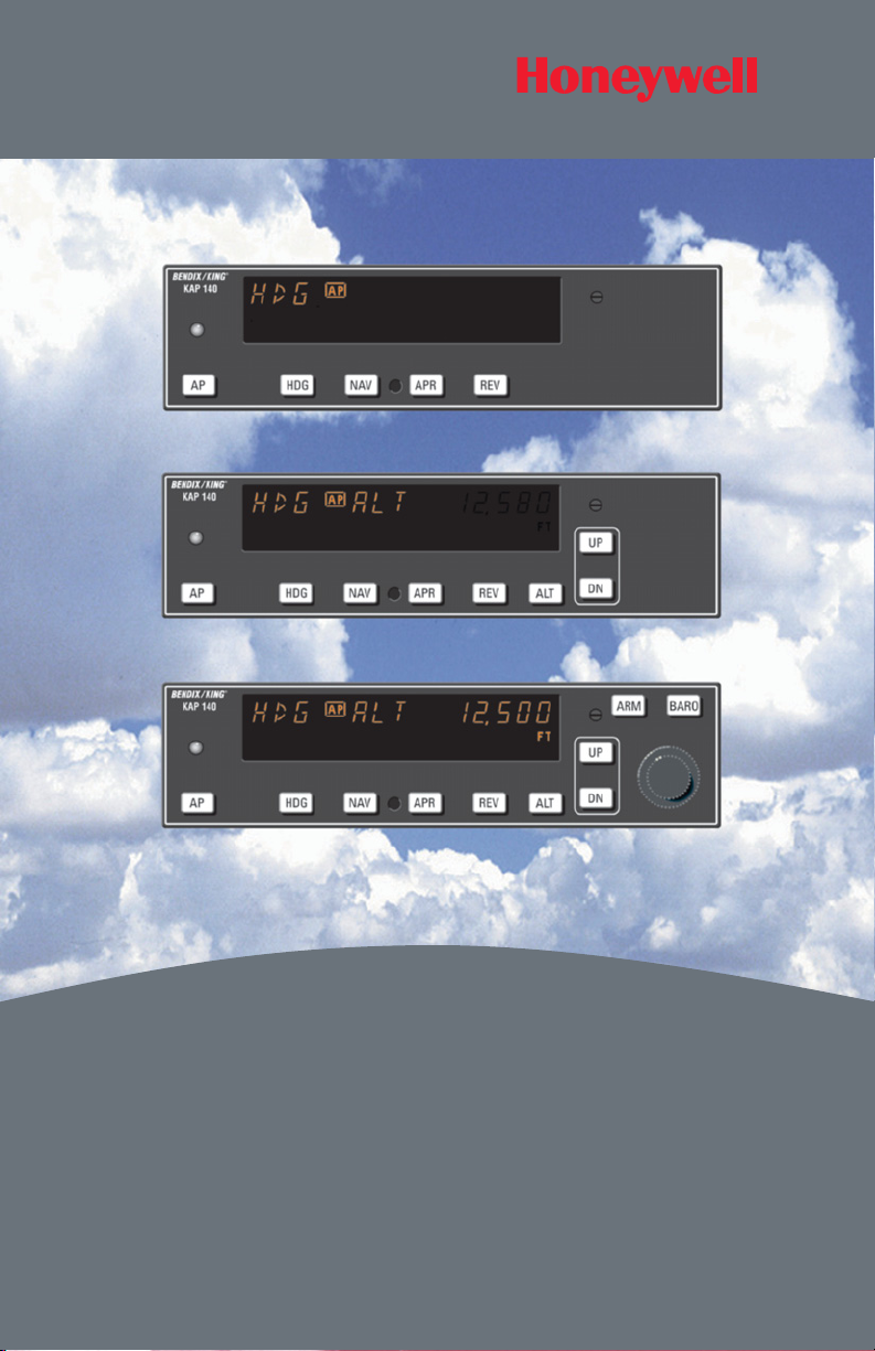
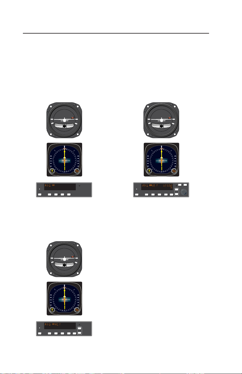
KAP 140 Single Axis
Autopilot System
The KAP 140 Single Axis system is
an entry level digital panel-mount
autopilot, offering lateral modes only
with an electric trim option.
D.C. ELEC.
TURN COORDINATOR
LR
2 MIN.
NO PITCH
INFORMATION
E
6
12
GS GS
3
15
N
S
33
21
0
3
24
W
ı
G
KAP 140
HDG NAV APR REV
AP
KAP 140 Two Axis
Autopilot System
The KAP 140 Two Axis system provides both lateral and vertical
modes.
KAP 140 Two Axis/Altitude
Preselect Autopilot System
The KAP 140 Two Axis system provides both lateral and vertical modes
with altitude preselect.
D.C. ELEC.
TURN COORDINATOR
LR
2 MIN.
NO PITCH
INFORMATION
E
6
12
GS GS
3
15
N
S
33
21
0
3
24
W
ı
G
KFC 140
AP
HDG NAV APR REV
ARM BARO
UP
DN
ALT
D.C. ELEC.
TURN COORDINATOR
LR
2 MIN.
NO PITCH
INFORMATION
3
N
GS GS
G
KAP 140
HDG NAV APR REV
AP
2
6
33
E
30
12
W
15
24
S
21
ı
UP
DN
ALT
KAP 140 AUTOPILOT SYSTEM
Rev. 1
Apr/02
Page 11

Introduction
KAP 140
Two Axis Alt.
Preselect
KAP 140
Two Axis
KAP 140
Single Axis
HSI Optional Optional Optional
DG Standard Standard Standard
Turn Coordinator Standard Standard Standard
Automatic Electric Elevator Trim Optional Optional
Manual Electric Trim Optional Optional
FUNCTIONS/MODES
ALT Hold (ALT) Yes Yes
ALT Preselect/ALERT Yes
Heading Select (HDG) Yes Yes Yes
NAV (VOR/RNAV/GPS) Yes Yes Yes
Approach (APR) Yes Yes Yes
Glideslope (GS) Yes Yes
Back Course (REV) Yes Yes Yes
Control Wheel Steering (CWS) Optional Optional Optional
Vertical Speed Hld Yes Yes
Auto Capture Yes Yes Yes
Auto Track Yes Yes Yes
All Angle Intercept
Standard (with
DG or optional
HSI)
Standard (with
DG or optional
HSI)
Standard (with
DG or optional
HSI)
Auto 45-degree Intercept
Standard
(with DG only)
Standard
(with DG only)
Standard
(with DG only)
TEST
Manual and Auto Trim Monitor Both Both Both
Acceleration Monitor Yes Yes
KAP 140 System Capabilities
Rev. 1
Apr/02
KAP 140 AUTOPILOT SYSTEM
3
Page 12

Introduction
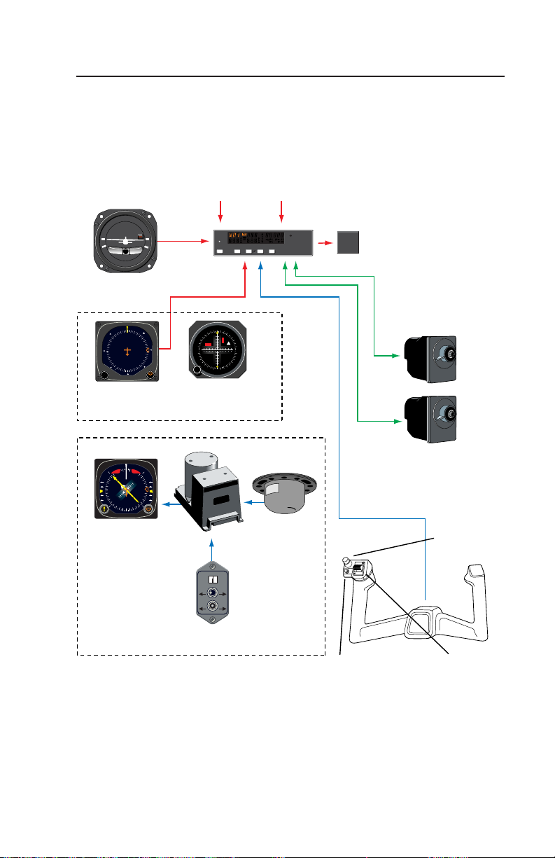
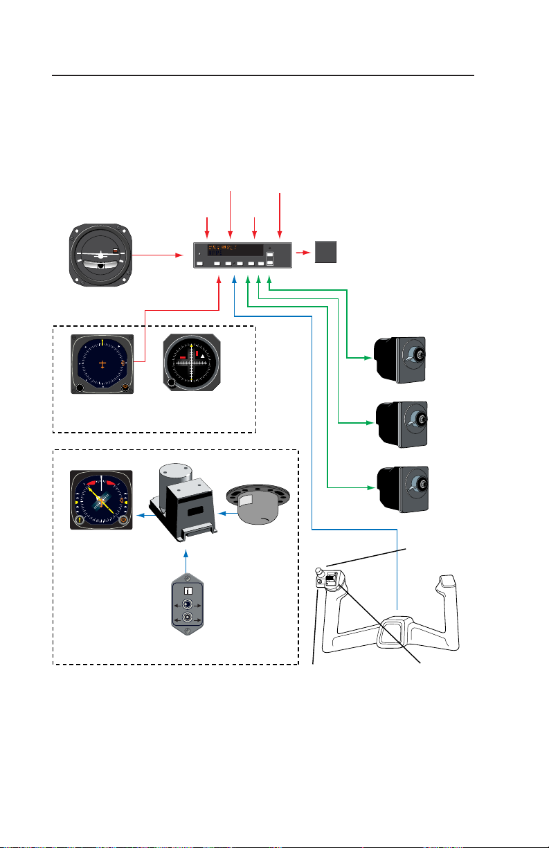
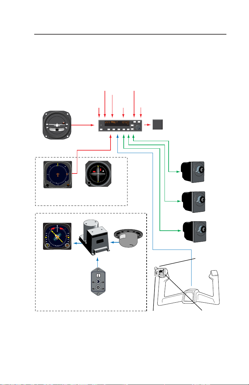
System Integration
The individual system diagrams on
pages 5, 6, and 7 show the components and their relationship in typical
KAP 140 Single Axis, KAP 140 Two
Axis, and KAP 140 Two Axis/Altitude
Preselect systems. The actual components on individual systems may
vary slightly in order to optimize certification and installation requirements.
Each system has a number of
inputs: sensor outputs are shown in
red; combination inputs are shown in
blue; display outputs are shown in
orange; and aircraft control shown in
green. The systems diagrams
reflect that the KAP 140 systems
control both pitch and roll axes of the
aircraft.
4
KAP 140 AUTOPILOT SYSTEM
Rev. 1
Apr/02
Page 13
D.C. ELEC.
TURN COORDINATOR
LR
2 MIN.
NO PITCH
INFORMATION
Turn Coordinator
Middle
Marker
G
KAP 140
AP
VOR/LOC/RNAV/
GPS Deviation
HDG NAV APR REV
TRIM
FAIL
Introduction
KC 140 Single Axis
Computer/Controller/
Annunciator
contains computer
functions, mode
control buttons,
and annunciations
in a single unit.
AIR
N
3
33
6
30
E
W
12
24
15
21
S
PUSH
P
H
U
S
Directional Gyro KI 204 or other Course
N
3
33
N
6
TO
30
A
V
GS
E
W
12
FR
24
15
21
S
OBS
ı
Deviation Indicator
OR
KG102A
ı
+
-
MANCWAUTO
CCW
KA 51B
Slaved DG
5
0
3
S
C
K
NAV HDG
N
3
3
3
GS GS
6
0
3
E
W
1
2
4
2
1
5
1
2
S
ı
KI 525A Pictorial
Navigation Indicator
KCS 55A Slaved
Compass System
(Optional)
Slaving Accessory
KMT 112
Flux Detector
Control
WheelSteering
(Optional)
KS 271C Roll Servo
KS 272C Pitch Trim
Servo (Optional)
Autopilot
Disconnect/
Trim Interrupt
(Optional)
Manual
Electrical Trim
(Optional)
Rev. 1
Apr/02
KAP 140 Single Axis System Diagram
KAP 140 AUTOPILOT SYSTEM
5
Page 14
Introduction
VOR/LOC/RNAV/
GPS Deviation
Glideslope
Deviation
D.C. ELEC.
TURN COORDINATOR
LR
2 MIN.
NO PITCH
INFORMATION
G
KAP 140
AP
HDG NAV APR REV
Turn Coordinator
AIR
N
3
33
6
30
E
W
12
24
15
21
S
PUSH
P
H
U
S
Directional Gyro KI 204 or other Course
N
3
33
N
6
TO
30
A
V
GS
E
W
12
FR
24
15
21
S
OBS
ı
Deviation Indicator
(not included)
OR
KG102A
ı
Slaved DG
5
0
3
S
C
K
NAV HDG
N
3
3
3
GS GS
6
0
3
E
W
1
2
4
2
1
5
1
2
S
ı
KI 525A Pictorial
Navigation Indicator
Pressure
Middle
Marker
DN
UP
ALT
KMT 112
Flux Detector
Static
KC 140 Two Axis
Computer/
Controller/
Annunciator
contains computer
functions, mode
TRIM
FAIL
control buttons,
and annunciations
in a single unit.
Also contains
static pressure
sensor and
accelerometer.
KS 271C Roll Servo
KS 270C Pitch Servo
KS 272C Pitch Trim Servo
Autopilot
Disconnect/
Trim Interrupt
KCS 55A Slaved
Compass System
(Optional)
6
+
-
MANCWAUTO
CCW
KA 51B
Slaving Accessory
Control
WheelSteering
(optional)
KAP 140 Two Axis System Diagram
KAP 140 AUTOPILOT SYSTEM
Manual
Electrical Trim
Rev. 1
Apr/02
Page 15
D.C. ELEC.
TURN COORDINATOR
LR
2 MIN.
NO PITCH
INFORMATION
Turn Coordinator
Baro
Setting
Glideslope
Deviation
G
KFC 140
AP
VOR/LOC/
RNAV/
GPS
Deviation
Middle
Marker
HDG NAV APR REV
Encoding
Altimeter
ARM BARO
UP
DN
ALT
Static
Pressure
TRIM
FAIL
Introduction
KC 140 Two Axis with
Altitude Preselect
Computer/Controller/
Annunciator
contains computer
functions, mode
control buttons,
and annunciations
in a single unit. Also
contains static pressure
sensor and accelerometer.
AIR
N
3
33
6
30
E
W
12
24
15
21
S
PUSH
P
H
U
S
Directional Gyro KI 204 or other Course
N
3
33
N
6
TO
30
A
V
GS
E
W
12
FR
24
15
21
S
OBS
ı
Deviation Indicator
(not included)
OR
KG102A
ı
-
CCW
Slaved DG
5
0
3
S
C
K
+
MANCWAUTO
NAV HDG
N
3
3
3
GS GS
6
0
3
E
W
1
2
4
2
1
5
1
2
S
ı
KI 525A Pictorial
Navigation Indicator
KCS 55A Slaved
Compass System
(Optional)
KA 51B
Slaving Accessory
KMT 112
Flux Detector
KS 271C Roll Servo
KS 270C Pitch Servo
KS 272C Pitch Trim Servo
Control
WheelSteering
(optional)
Autopilot
Disconnect/
Trim Interrupt
Manual
Electrical Trim
Rev. 1
Apr/02
KAP 140 Two Axis/Altitude Preselect System Diagram
KAP 140 AUTOPILOT SYSTEM
7
Page 16
Introduction
Power Application and Preflight Tests
G
KAP 140
AP
HDG NAV APR REV
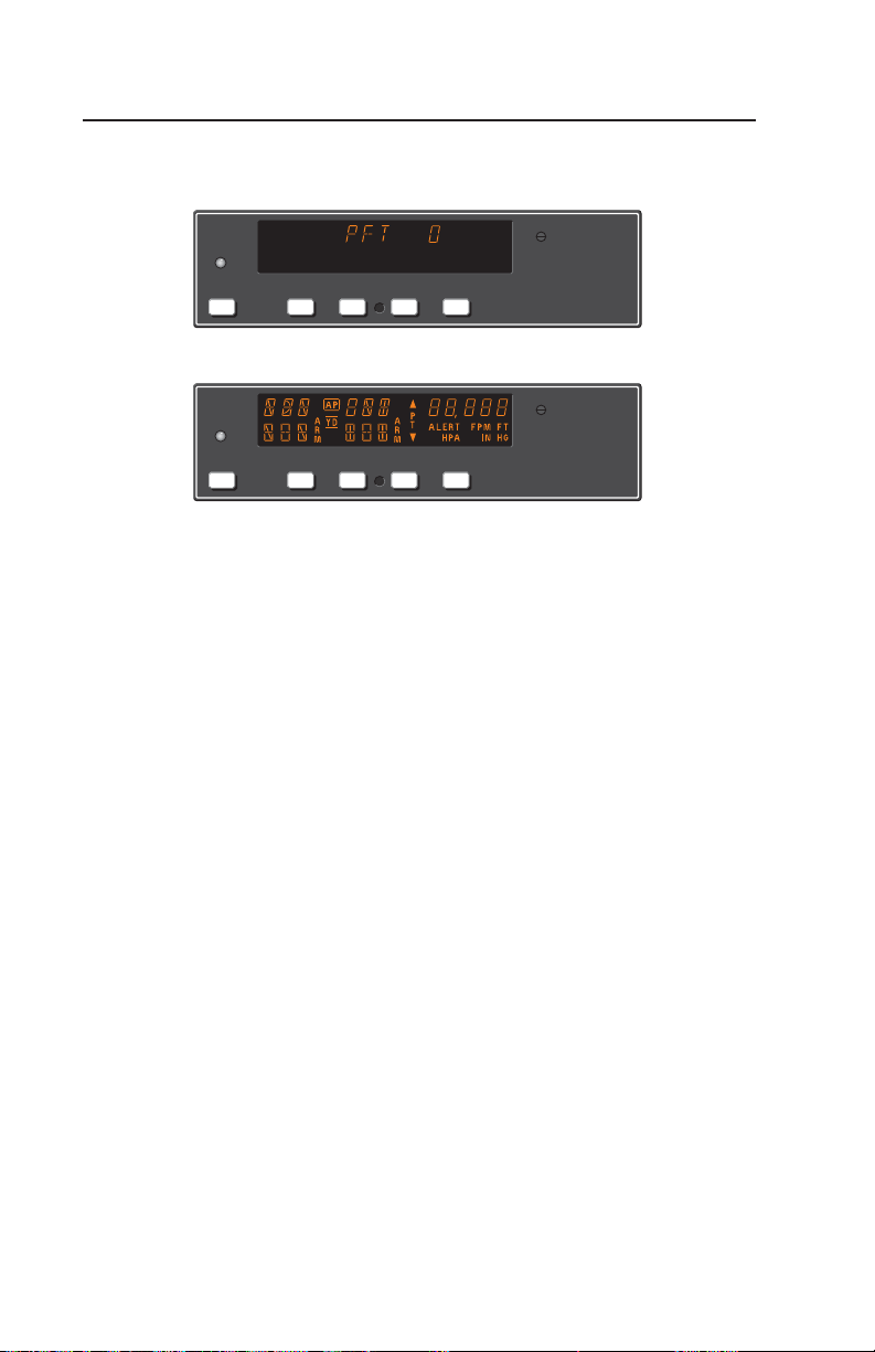
KAP 140 Preflight Test
G
KAP 140
AP
HDG NAV APR REV
KAP 140 Preflight Test Complete
A preflight test is performed
upon power application to the computer. This test is a sequence of
internal checks that validate proper
system operation prior to allowing
autopilot engagement. The preflight
test (PFT) sequence is indicated by
“PFT” with an increasing number for
the sequence steps. Successful
completion of self test is identified by
all display segments being illuminated (Display Test) and the disconnect tone sounding.
For two-axis units only:
NOTE: Following the preflight test,
the red P warning on the face of the
autopilot may illuminate indicating
that the pitch axis cannot be
engaged. This condition should be
temporary, lasting no more than 30
seconds. The P will extinguish and
normal operation will be available.
NOTE: The red P warning may illuminate when the autopilot is not
engaged. This can occur when
autopilot G limits have been
exceeded during turbulence or aircraft maneuvering. Autopilot
engagement is locked out during red
P illumination.
If power to the autopilot is cycled in
flight (i.e. through the autopilot circuit
breaker for instance) it is possible
that a 5 minute delay may be necessary prior to autopilot engagement to
allow the pitch axis accelerometer
circuit to stabilize. Engagement prior
to stabilization may result in mildly
erratic pitch axis behavior.
8
KAP 140 AUTOPILOT SYSTEM
Rev. 1
Apr/02
Page 17

Single Axis Operation
KAP 140 Single Axis Operation
The KAP 140 is a high-performance digital, panel-mounted autopilot sys-
tem for light aircraft.
8
7
G
KAP 140
P R
AP
Single-axis Flight Control Computer
G
KAP 140
P R
AP
1 3 4 5 62
Full Single-axis KAP 140 Display
1. AUTOPILOT ENGAGE/DISEN-
GAGE (AP) BUTTON - When
pushed, engages autopilot if all logic
conditions are met. The autopilot
will engage in the basic roll (ROL)
mode which functions as a wing lev-
eler. When pressed again, will disen-
gage the autopilot. For software ver-
sion 03/01 and later, the AP button
must be pressed and held for 0.25
seconds to engage the autopilot.
2. ROLL AXIS (R) ANNUNCIATION
- When illuminated, indicates failure
of the roll axis and will disengage the
autopilot and not allow engagement.
3. HEADING (HDG) MODE SELEC-
TOR BUTTON - When pushed, will
select the Heading mode, which
commands the airplane to turn to
HDG NAV APR REV
HDG NAV APR REV
and maintain the heading selected
by the heading bug on either the DG
or HSI. A new heading may be
selected at any time and will result in
the airplane turning to the new heading. Button can also be used to toggle between HDG and ROL modes.
This button will engage the autopilot
in units with software prior to software version 03/01.
4. NAVIGATION (NAV) MODE
SELECTOR BUTTON - When
pushed, will arm the navigation
mode. The mode provides automatic beam capture and tracking of
VOR, LOC or GPS as selected for
presentation on the HSI or CDI.
NAV mode is recommended for
enroute navigation tracking.
Rev. 2
May/02
KAP 140 AUTOPILOT SYSTEM
9
Page 18

Single Axis Operation
5. APPROACH (APR) MODE
SELECTOR BUTTON - When
pushed, will arm the Approach
mode. This mode provides automatic beam capture and tracking of
VOR, GPS and LOC, as selected for
presentation on the HSI or CDI.
APR mode is recommended for
instrument approaches.
6. BACK COURSE APPROACH
(REV) MODE SELECTOR BUTTON
- When pushed, will arm the Back
Course approach mode. This mode
functions similarly to the approach
mode except that the autopilot
response to LOC signals is
reversed.
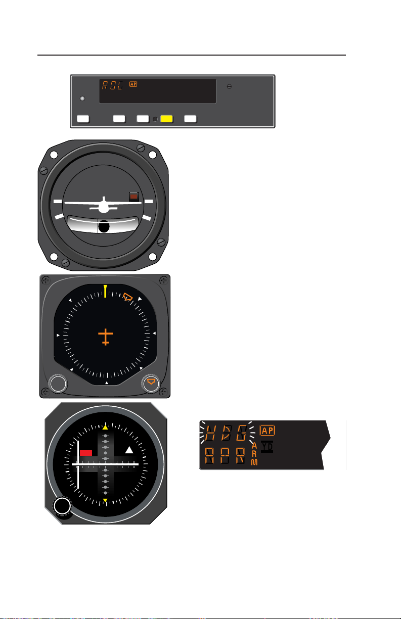
7. ROLL MODE DISPLAY Displays the active and armed roll
modes (ROL, HDG, NAV ARM,
NAV, APR ARM, APR, REV ARM,
REV). Also displayed will be flashing AP annunciation (5 seconds) at
each autopilot disconnect accompanied by an aural tone (for 2 seconds).
8. AUTOPILOT ENGAGED (AP)
ANNUNCIATION - Illuminates
whenever the autopilot is engaged.
Flashes during pilot initiated or automatic disengagement. Only applicable for software versions 03/01 or
later.
10
KAP 140 AUTOPILOT SYSTEM
Rev. 1
Apr/02
Page 19

Single Axis Operation
This page intentionally left blank
Rev. 1
Apr/02
KAP 140 AUTOPILOT SYSTEM
11
Page 20
Single Axis Operation
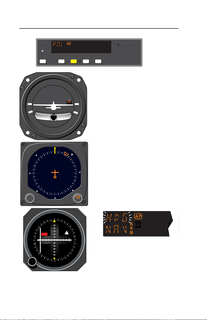
System Operating Modes
G
KAP 140
AP
HDG NAV APR REV
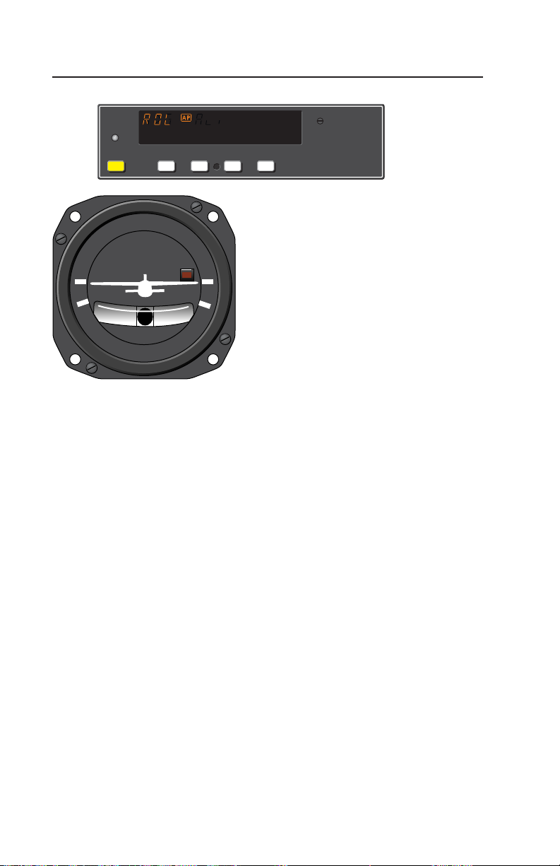
Wing Leveler (ROL) Mode
D.C. ELEC.
In the roll mode, the autopilot
maintains wings level flight.
TURN COORDINATOR
1. Engage autopilot - Press AP.
For software version 03/01 and later,
the AP button must be pressed and
LR
2 MIN.
NO PITCH
INFORMATION
held for 0.25 seconds to engage the
autopilot.
NOTE: The KAP 140 engages into
ROL mode as a default.
12
KAP 140 AUTOPILOT SYSTEM
Rev. 2
May/02
Page 21
G
KAP 140
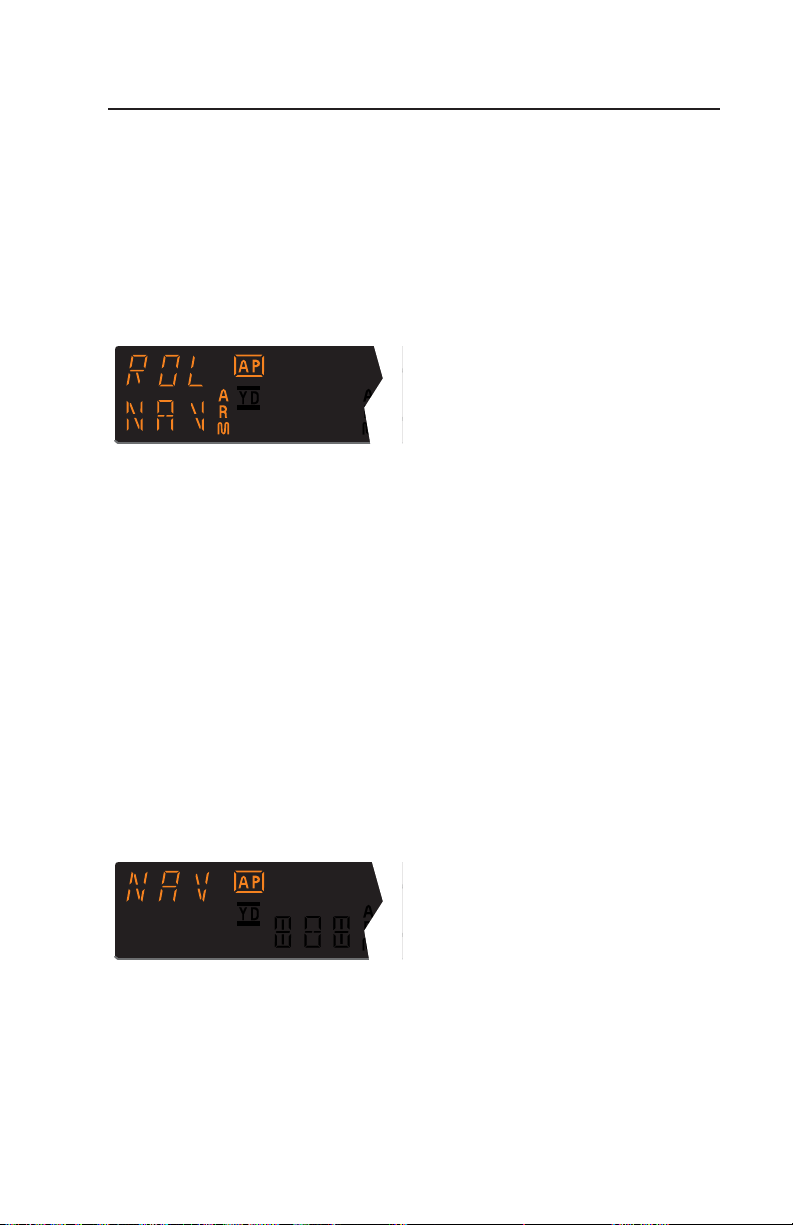
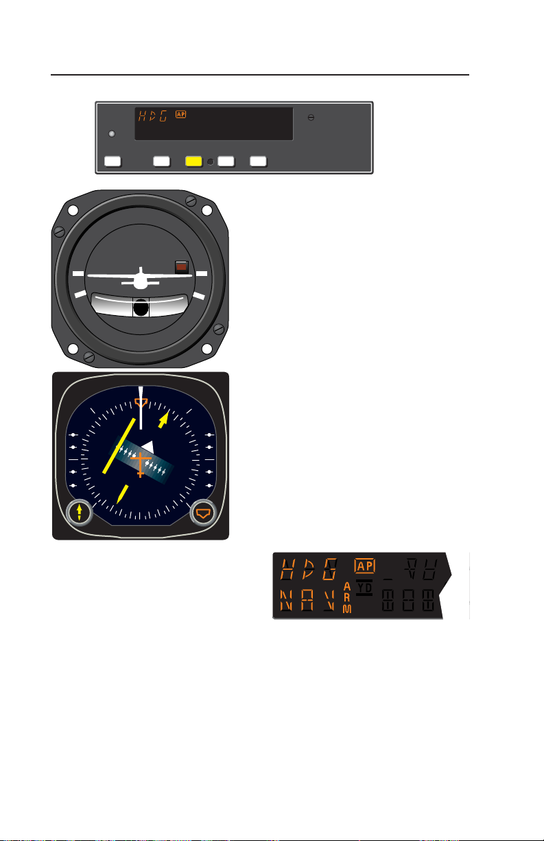
Single Axis Operation
AP
HDG NAV APR REV
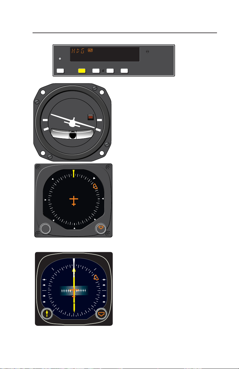
Heading Select (HDG) Mode
D.C. ELEC.
autopilot will fly a selected heading.
TURN COORDINATOR
LR
2 MIN.
NO PITCH
INFORMATION
The following steps should be taken
to operate in the heading mode:
the desired heading on the DG or
HSI using the Heading Select knob.
For software version 03/01 and later,
the AP button must be pressed and
held for 0.25 seconds to engage the
autopilot.
the KAP 140 to engage the heading
select mode. The autopilot will turn
the aircraft in the shortest direction
to intercept and fly the heading.
“bug” again while the heading select
PUSH
N
33
30
W
24
3
6
E
12
21
15
S
P
H
U
S
mode is engaged, the autopilot will
immediately turn the aircraft in the
direction of the newly selected heading.
N
33
GS GS
30
W
24
3
6
E
12
21
15
S
the autopilot will return to the ROL
mode.
In the heading mode, the
1. Move the heading “bug” to
2. Engage autopilot - Press AP.
3. Depress the HDG button on
4. If you move the heading
5. Press HDG button again and
Rev. 2
May/02
ı
KAP 140 AUTOPILOT SYSTEM
13
Page 22

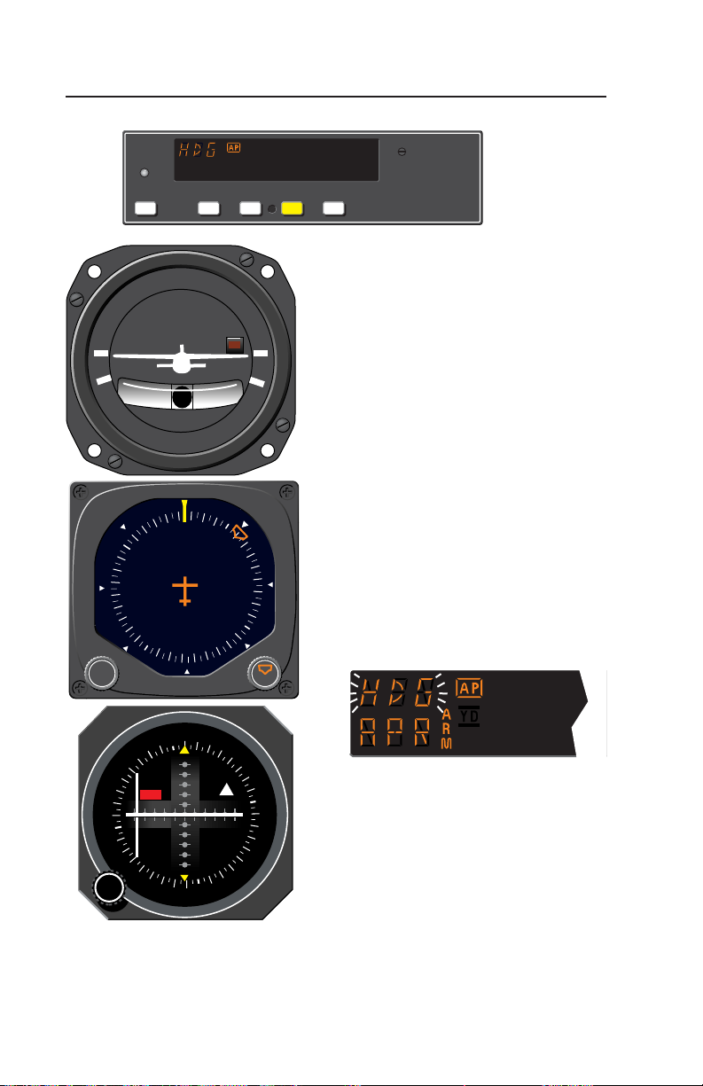
Single Axis Operation
G
KAP 140
AP
HDG NAV APR REV
Navigation (NAV) Mode Using a
D.C. ELEC.
TURN COORDINATOR
DG from HDG Mode
(45° Intercept)
the autopilot intercepts and tracks
VOR/RNAV and GPS courses.
LR
2 MIN.
NO PITCH
INFORMATION
KAP 140 currently in the HDG
mode):
1. Select the desired frequency for
VOR or RNAV. For GPS, verify
the desired waypoint or destination.
2. OBS Knob - SELECT desired
course.
3. NAV Mode Selector Button PRESS. Note NAV ARM annunci-
PUSH
6
3
N
33
30
W
E
12
15
S
21
24
P
H
U
S
In the navigation (NAV) mode,
To arm NAV mode (with the
14
OBS
E
30
ı
12
15
N
TO
A
V
W
S
21
FR
24
6
3
GS
N
33
KAP 140 AUTOPILOT SYSTEM
ated.
NOTE: When NAV is selected, the
autopilot will flash HDG for 5 seconds to remind the pilot to reset the
HDG bug to the OBS course. Check
the heading displayed on the DG
against the magnetic compass and
reset if necessary.
Rev. 1
Apr/02
Page 23

4. Heading Selector Knob ROTATE BUG to agree with OBS
course.
Note Instruments: CDI needle to left.
Intercept heading 45° to the left of
selected (heading bug) course.
5. If the Course Deviation Bar is
greater than 2 to 3 dots: the
autopilot will annunciate NAV
ARM; when the computed capture
point is reached the ARM annunciator will go out and the selected
course will be automatically captured and tracked. If the D-Bar is
less than 2 to 3 dots: the HDG
mode will disengage upon selecting NAV mode; the NAV annunci-
ator will illuminate and the capture/
track sequence will automatically
begin.
Single Axis Operation
Rev. 1
Apr/02
KAP 140 AUTOPILOT SYSTEM
15
Page 24
Single Axis Operation
G
KAP 140
AP
HDG NAV APR REV
Navigation (NAV) Mode Using a
D.C. ELEC.
TURN COORDINATOR
DG from ROL Mode
(All Angle Intercept)
the autopilot intercepts and tracks
VOR/RNAV and GPS courses.
LR
2 MIN.
NO PITCH
INFORMATION
KAP 140 currently in the ROL
mode):
1. Maneuver the aircraft to the
desired intercept angle prior to
selecting ROL mode.
PUSH
6
3
N
33
30
E
12
15
S
21
24
W
P
H
U
S
2. Select the desired frequency for
VOR or RNAV. For GPS, verify
the desired waypoint or destination.
3. OBS Knob - SELECT desired
course.
4. NAV Mode Selector Button PRESS. Note NAV ARM annunci-
ated.
In the navigation (NAV) mode,
To arm NAV mode (with the
16
OBS
E
30
ı
12
15
N
TO
A
V
W
S
21
FR
24
NOTE: When NAV is selected, the
autopilot will flash HDG for 5 seconds to remind the pilot to reset the
HDG bug to the OBS course. Check
the heading displayed on the DG
against the magnetic compass and
6
3
GS
N
33
reset if necessary.
KAP 140 AUTOPILOT SYSTEM
Rev. 1
Apr/02
Page 25
5. Heading Selector Knob ROTATE BUG to agree with OBS
course.
Note Instruments: CDI needle to left.
Intercept heading 30° to the left of
selected (heading bug) course.
6. If the Course Deviation Bar is
greater than 2 to 3 dots: the
autopilot will annunciate NAV
ARM; when the computed capture
point is reached the ARM annunciator will go out and the selected
course will be automatically captured and tracked. If the D-Bar is
less than 2 to 3 dots: the ROL
mode will disengage upon selecting NAV mode; the NAV annunciator will illuminate and the capture/
track sequence will automatically
begin.
Single Axis Operation
Note: Intercept angles greater than
45° can result in course overshoot
when close to the station.
Therefore, intercept angles greater
than 45° are not recommended.
Rev. 1
Apr/02
KAP 140 AUTOPILOT SYSTEM
17
Page 26
Single Axis Operation
G
KAP 140
AP
HDG NAV APR REV
Navigation (NAV) Mode Using an
D.C. ELEC.
HSI
In the navigation (NAV) mode,
TURN COORDINATOR
the autopilot intercepts and tracks
VOR/RNAV and GPS courses.
LR
2 MIN.
NO PITCH
INFORMATION
To arm NAV mode (with the
KAP 140 currently in the HDG
mode):
1. Select the desired frequency for
VOR or RNAV. For GPS, verify
the desired waypoint or destination.
6
E
3
GS GS
N
33
30
12
15
S
21
24
W
2. Course Bearing Pointer - SET
to desired course.
3. Heading Selector Knob - SET
BUG to provide desired intercept
angle.
4. NAV Mode Selector Button PRESS.
ı
Note NAV ARM annunciated.
18
KAP 140 AUTOPILOT SYSTEM
Rev. 1
Apr/02
Page 27

5. If the Course Deviation Bar is
greater than 2 to 3 dots: the aircraft will continue in HDG mode
(or ROL if HDG is not selected)
with NAV ARM annunciated;
when the computed capture point
is reached HDG will disengage,
the ARM annunciator will go out
and the selected course will be
automatically captured and
tracked. If the D-Bar is less than 2
to 3 dots: the HDG mode (or ROL
if HDG is not selected) will disen-
gage upon selecting NAV mode;
the NAV annunciator will illuminate and the capture/ track
sequence will automatically begin.
Single Axis Operation
Note: Intercept angles greater than
45° can result in course overshoot
when close to the station. Therefore,
intercept angles greater than 45° are
not recommended.
Rev. 1
Apr/02
KAP 140 AUTOPILOT SYSTEM
19
Page 28
Single Axis Operation
G
KAP 140
AP
HDG NAV APR REV
Approach (APR) Mode Using a
D.C. ELEC.
TURN COORDINATOR
DG from HDG Mode
(45° Intercept)
allows the autopilot to intercept and
track LOC, VOR/RNAV and GPS
courses.
LR
2 MIN.
NO PITCH
INFORMATION
KAP 140 currently in the HDG
mode):
1. Select the desired frequency for
LOC, VOR or RNAV. For GPS,
6
3
N
33
30
W
E
12
15
S
21
24
verify the desired approach.
2. OBS Knob - SELECT desired
approach course. (For a localizer,
set it to serve as a memory aid.)
3. APR Mode Selector Button PRESS. Note APR ARM annun-
ciated.
PUSH
P
H
U
S
The Approach (APR) mode
To arm APR mode (with the
20
OBS
E
30
ı
12
15
N
TO
A
V
W
S
21
FR
24
KAP 140 AUTOPILOT SYSTEM
NOTE: When APR is selected, the
autopilot will flash HDG for 5 seconds to remind the pilot to reset the
HDG bug to the desired approach
course. Check the heading displayed on the DG against the magnetic compass and reset if necessary.
Rev. 1
Apr/02
6
3
GS
N
33
Page 29

4. Heading Selector Knob ROTATE BUG to agree with
desired approach course.
Note Instruments: CDI needle to left.
Intercept heading 45° to the left of
selected (heading bug) course.
5. If the Course Deviation Bar is
greater than 2 to 3 dots: the
autopilot will annunciate APR
ARM; when the computed capture
point is reached the ARM annunciator will go out and the selected
course will be automatically captured and tracked. If the D-Bar is
less than 2 to 3 dots: the HDG
mode will disengage upon selecting APR mode; the APR annunciator will illuminate and the capture/
track sequence will automatically
begin.
Single Axis Operation
Rev. 1
Apr/02
KAP 140 AUTOPILOT SYSTEM
21
Page 30
Single Axis Operation
G
KAP 140
AP
HDG NAV APR REV
Approach (APR) Mode Using a
D.C. ELEC.
TURN COORDINATOR
DG from ROL Mode
(All Angle Intercept)
allows the autopilot to intercept and
track LOC, VOR/RNAV and GPS
courses.
LR
2 MIN.
NO PITCH
INFORMATION
KAP 140 currently in the ROL
mode):
1. Maneuver the aircraft to the
desired intercept angle prior to
6
E
3
N
33
30
12
15
S
21
24
W
selecting ROL mode.
2. Select the desired frequency for
LOC, VOR or RNAV. For GPS,
verify the desired approach.
3. OBS Knob - SELECT desired
approach course. (For a localizer,
set it to serve as a memory aid.)
PUSH
P
H
U
S
4. APR Mode Selector Button PRESS. Note APR ARM annun-
ciated.
E
6
3
GS
12
15
N
TO
A
V
S
The Approach (APR) mode
To arm APR mode (with the
22
OBS
N
33
30
ı
21
FR
24
W
NOTE: When APR is selected, the
autopilot will flash HDG for 5 seconds to remind the pilot to reset the
HDG bug to the desired approach
course. Check the heading displayed on the DG against the magnetic compass and reset if necessary.
KAP 140 AUTOPILOT SYSTEM
Rev. 1
Apr/02
Page 31

5. Heading Selector Knob ROTATE BUG to agree with
desired approach course.
Note Instruments: CDI needle to left.
Intercept heading 30° to the left of
selected (heading bug) course.
6. If the Course Deviation Bar is
greater than 2 to 3 dots: the
autopilot will annunciate APR
ARM; when the computed capture
point is reached the ARM annunciator will go out and the selected
course will be automatically captured and tracked. If the D-Bar is
less than 2 to 3 dots: the ROL
mode will disengage upon selecting APR mode; the APR annunciator will illuminate and the capture/
track sequence will automatically
begin.
Single Axis Operation
Note: Intercept angles greater than
45° can result in course overshoot
when close to the station.
Therefore, intercept angles greater
than 45° are not recommended.
Rev. 1
Apr/02
KAP 140 AUTOPILOT SYSTEM
23
Page 32

Single Axis Operation
G
KAP 140
AP
HDG NAV APR REV
Approach (APR) Mode Using an
D.C. ELEC.
HSI
The Approach (APR) mode
TURN COORDINATOR
allows the autopilot to intercept and
track LOC, VOR/RNAV and GPS
courses.
LR
2 MIN.
NO PITCH
INFORMATION
To arm APR mode (with the
KAP 140 currently in the HDG
mode):
1. Select the desired frequency for
LOC, VOR or RNAV. For GPS,
verify the desired approach.
6
E
3
GS GS
N
33
30
12
15
S
21
24
W
2. Course Bearing Pointer - SET
to desired course.
3. Heading Selector Knob - SET
BUG to provide desired intercept
angle.
4. APR Mode Selector Button PRESS. Note APR ARM annun-
ı
ciated.
24
KAP 140 AUTOPILOT SYSTEM
Rev. 1
Apr/02
Page 33

5. If the Course Deviation Bar is
greater than 2 to 3 dots: the aircraft will continue in HDG mode
(or ROL if HDG is not selected)
with the APR ARM annunciated;
when the computed capture point
is reached HDG mode will disengage, the ARM annunciator will go
out and the selected course will be
automatically captured and
tracked. If the D-Bar is less than 2
to 3 dots: the HDG mode (or ROL
if HDG is not selected) will disen-
gage upon selecting APR mode;
the APR annunciator will illuminate and the capture/track
sequence will automatically begin.
Single Axis Operation
Note: Intercept angles greater than
45° can result in course overshoot
when close to the station.
Therefore, intercept angles greater
than 45° are not recommended.
Rev. 1
Apr/02
KAP 140 AUTOPILOT SYSTEM
25
Page 34

Single Axis Operation
G
KAP 140
AP
HDG NAV APR REV
Back Course (REV) Mode Using
D.C. ELEC.
TURN COORDINATOR
a DG from HDG Mode
(45° Intercept)
allows the autopilot to intercept and
track a localizer back course.
LR
2 MIN.
NO PITCH
INFORMATION
KAP 140 currently in the HDG
mode):
1. Select the desired frequency for
LOC.
2. OBS Knob - SELECT front
PUSH
24
21
S
15
12
E
W
30
33
N
3
6
P
H
U
S
course inbound heading.
3. REV Mode Selector Button PRESS. Note REV ARM annun-
ciated.
The Back Course (REV) mode
To arm REV mode (with the
26
OBS
E
ı
12
15
N
TO
A
V
S
21
FR
24
W
6
3
GS
N
33
30
KAP 140 AUTOPILOT SYSTEM
NOTE: When REV is selected, the
autopilot will flash HDG for 5 seconds to remind the pilot to reset the
HDG bug to the front course inbound
heading. Check the heading displayed on the DG against the magnetic compass and reset if necessary.
Rev. 1
Apr/02
Page 35

4. Heading Selector Knob ROTATE BUG to agree with the
FRONT COURSE inbound heading.
Note Instruments: CDI needle to the
right. Intercept heading 45° to the left
of the back course.
5. If the Course Deviation Bar is
greater than 2 to 3 dots: the
autopilot will annunciate REV
ARM; when the computed capture
point is reached the ARM annunciator will go out and the selected
course will be automatically captured and tracked. If the D-Bar is
less than 2 to 3 dots: the HDG
mode will disengage upon selecting REV mode; the REV annunciator will illuminate and the capture/
track sequence will automatically
begin.
Single Axis Operation
Rev. 1
Apr/02
KAP 140 AUTOPILOT SYSTEM
27
Page 36

Single Axis Operation
G
KAP 140
AP
HDG NAV APR REV
Back Course (REV) Mode Using a
D.C. ELEC.
TURN COORDINATOR
DG from ROL Mode
(All Angle Intercept)
allows the autopilot to intercept and
track a localizer back course.
LR
2 MIN.
NO PITCH
INFORMATION
KAP 140 currently in the ROL
mode):
1. Maneuver the aircraft to the
desired intercept angle prior to
selecting ROL mode.
PUSH
24
21
S
15
12
E
W
30
33
N
3
6
P
H
U
S
2. Select the desired frequency for
LOC.
3. OBS Knob - SELECT front
course inbound heading.
4. REV Mode Selector Button PRESS. Note REV ARM annunci-
ated.
The Back Course (REV) mode
To arm REV mode (with the
28
OBS
E
6
3
GS
N
33
30
12
15
N
TO
A
V
S
21
FR
24
W
ı
KAP 140 AUTOPILOT SYSTEM
NOTE: When REV is selected, the
autopilot will flash HDG for 5 seconds to remind the pilot to reset the
HDG bug to the front course inbound
heading. Check the heading displayed on the DG against the magnetic compass and reset if necessary.
Rev. 1
Apr/02
Page 37

5. Heading Selector Knob ROTATE BUG to agree with the
FRONT COURSE inbound heading.
Note Instruments: CDI needle to the
right. Intercept heading 30° to the left
of the back course.
6. If the Course Deviation Bar is
greater than 2 to 3 dots: the
autopilot will annunciate REV
ARM; when the computed capture
point is reached the ARM annunciator will go out and the selected
course will be automatically captured and tracked. If the D-Bar is
less than 2 to 3 dots: the HDG
mode will disengage upon selecting REV mode; the REV annunciator will illuminate and the capture/
track sequence will automatically
begin.
Single Axis Operation
Note: Intercept angles greater than
45° can result in course overshoot
when close to the station.
Therefore, intercept angles greater
than 45° are not recommended.
Rev. 1
Apr/02
KAP 140 AUTOPILOT SYSTEM
29
Page 38

Single Axis Operation
G
KAP 140
AP
HDG NAV APR REV
Back Course (REV) Mode Using
D.C. ELEC.
an HSI
The Back Course (REV) mode
TURN COORDINATOR
allows the autopilot to intercept and
track a localizer back course.
To arm REV mode (with the
LR
2 MIN.
NO PITCH
INFORMATION
KAP 140 currently in the HDG
mode):
1. Select the desired frequency for
LOC.
2. Course Bearing Pointer - SET
to the FRONT COURSE inbound
24
21
GS GS
S
15
12
W
30
33
N
E
3
6
heading.
3. Heading Selector Knob - SET
BUG to provide desired intercept
angle.
4. REV Mode Selector Button PRESS. Note REV ARM annunci-
ated.
ı
30
KAP 140 AUTOPILOT SYSTEM
Rev. 1
Apr/02
Page 39

5. If the Course Deviation Bar is
greater than 2 to 3 dots: the aircraft will continue in HDG mode
(or ROL if HDG is not selected)
with the REV ARM annunciated;
when the computed capture point
is reached HDG mode will disengage, the ARM annunciator will go
out and the selected course will be
automatically captured and
tracked. If the D-Bar is less than 2
to 3 dots: the HDG mode (or ROL
if HDG is not selected) will disen-
gage upon selecting REV mode;
the REV annunciator will illuminate and the capture/track
sequence will automatically begin.
Single Axis Operation
Note: Intercept angles greater than
45° can result in course overshoot
when close to the station.
Therefore, intercept angles greater
than 45° are not recommended.
Rev. 1
Apr/02
KAP 140 AUTOPILOT SYSTEM
31
Page 40

KAP 140 AUTOPILOT SYSTEM
Single Axis Operation Single Axis Operation
32 33
KAP 140 AUTOPILOT SYSTEM
Rev. 1
Apr/02
Rev. 1
Apr/02
OPERATIONS WITH THE KAP 140
Takeoff And Climb To Assigned Altitude
3. The autopilot is responding to the heading select
mode with a left bank.
4. The autopilot has completed the turn and is
now established on a 010° heading.
1. The aircraft is well off the ground and established at a desired climb rate.
The heading bug on the DG or HSI is turned to
the desired heading of 080° (runway heading).
By depressing the
HDG
button on the KAP 140,
the autopilot engages into the heading mode
and maintains the selected heading of 080°.
Note: Press and hold the APbutton for 0.25
seconds to engage the autopilot (applicable
only to software version 03/01 and later).
2. The heading bug on the DG or HSI is turned to
the new desired heading of 010° and the aircraft
begins to respond with an immediate left turn.
Note: The autopilot controls only the roll axis. The PILOT must maintain control of
the pitch and yaw axis.
N
1234
123 4
080°
°
010
D.C. ELEC.
TURN COORDINATOR
LR
2 MIN.
NO PITCH
INFORMATION
E
6
12
3
33
30
G
W
KAP 140
AP
15
S
21
24
P
H
U
S
HDG NAV APR REV
OR
N
PUSH
E
6
GS GS
12
3
N
33
15
21
30
24
W
ı
S
D.C. ELEC.
TURN COORDINATOR
LR
2 MIN.
NO PITCH
INFORMATION
E
6
12
3
33
30
G
KAP 140
AP
15
S
21
24
W
P
HDG NAV APR REV
OR
H
U
S
N
PUSH
E
6
GS GS
12
3
N
15
33
21
30
24
W
ı
S
D.C. ELEC.
TURN COORDINATOR
LR
2 MIN.
NO PITCH
INFORMATION
3
6
E
N
W
G
KAP 140
24
AP
12
15
S
21
P
H
U
S
HDG NAV APR REV
OR
33
30
PUSH
3
6
E
N
GS GS
3
3
30
S
W
4
21
2
ı
12
1
5
D.C. ELEC.
TURN COORDINATOR
LR
2 MIN.
NO PITCH
INFORMATION
N
3
6
33
24
G
KAP 140
21
AP
E
12
15
S
P
H
U
S
HDG NAV APR REV
OR
30
W
PUSH
3
N
6
3
GS GS
3
0
3
W
1
4
5
2
1
S
2
ı
E
1
2
Page 41

KAP 140 AUTOPILOT SYSTEM
Single Axis Operation Single Axis Operation
34 35
KAP 140 AUTOPILOT SYSTEM
Rev. 1
Apr/02
Rev. 1
Apr/02
3. When the computed capture point is reached,
the
ROL
annunciation changes to
NAV
and a
right turn is initiated by the autopilot.
4. The turn is complete and the autopilot is tracking the GPS course.
1. Continuing on heading 010°, a GPS waypoint is
established. A 30° intercept is desired.
2. The
HDG
button is depressed to select
ROL
mode which will allow an “all angle intercept”.
GPS data is selected for the CDI and the OBS is
set to 040°. The
NAV
button is depressed and
NAV ARM
is annunciated.
ROL
will change to
HDG
and flash for five seconds.
ROL
will then
be redisplayed. While the
HDG
annunciation is
flashing, move the heading bug to the desired
course of 040°. The aircraft will remain wings
level until the capture point.
GPS Capture Using DG
* Description of GPS operation based on Bendix/King GPS receiver. Others may
require different operation.
N
4
3
D.C. ELEC.
TURN COORDINATOR
LR
2 MIN.
NO PITCH
INFORMATION
E
12
N
3
33
6
24
G
KAP 140
21
AP
E
12
15
S
P
H
U
S
HDG NAV APR REV
30
W
PUSH
6
3
GS
N
33
OBS
15
TO
S
21
FR
24
30
W
ı
D.C. ELEC.
TURN COORDINATOR
LR
2 MIN.
NO PITCH
INFORMATION
3
N
3
6
33
30
W
PUSH
E
12
15
24
S
G
KAP 140
21
AP
P
H
U
S
HDG NAV APR REV
OBS
6
N
33
GS
30
W
E
TO
12
15
FR
S
24
21
ı
°
0
4
D.C. ELEC.
TURN COORDINATOR
LR
2 MIN.
NO PITCH
INFORMATION
3
3
6
N
W
G
KAP 140
24
AP
E
12
15
S
21
P
H
U
S
HDG NAV APR REV
30
OBS
33
30
PUSH
6
N
33
GS
W
E
TO
12
15
FR
S
24
21
ı
2
°
010
1
D.C. ELEC.
TURN COORDINATOR
LR
2 MIN.
NO PITCH
INFORMATION
3
6
E
N
W
G
24
KAP 140
AP
12
15
S
21
P
H
U
S
HDG NAV APR REV
33
30
PUSH
N
33
GS
30
W
OBS
3
6
E
TO
12
15
FR
S
24
21
ı
Page 42

KAP 140 AUTOPILOT SYSTEM
Single Axis Operation Single Axis Operation
36 37
KAP 140 AUTOPILOT SYSTEM
Rev. 1
Apr/02
Rev. 1
Apr/02
3. When the computed capture point is reached,
the
HDG
annunciation changes to
NAV
and a
right turn is initiated by the autopilot.
4. The turn is complete and the autopilot is tracking the GPS course.
1. Continuing on heading 010°, a GPS waypoint is
established. A 30° intercept is desired.
2. GPS data is selected for the HSI. The course
pointer is set to 040°. The
NAV
button is
depressed and
NAV ARM
is annunciated.
GPS Capture Using HSI
* Description of GPS operation based on Bendix/King GPS receiver. Others may
require different operation.
N
4
3
D.C. ELEC.
TURN COORDINATOR
LR
2 MIN.
NO PITCH
INFORMATION
3
N
6
33
30
W
E
12
15
24
S
21
ı
G
KAP 140
AP
GS GS
HDG NAV APR REV
G
KAP 140
AP
D.C. ELEC.
TURN COORDINATOR
LR
2 MIN.
NO PITCH
INFORMATION
N
GS GS
HDG NAV APR REV
3
6
33
30
W
E
12
15
24
S
21
ı
°
0
4
D.C. ELEC.
TURN COORDINATOR
LR
2 MIN.
NO PITCH
INFORMATION
3
6
N
G
KAP 140
AP
GS GS
33
30
HDG NAV APR REV
E
12
24
ı
15
S
21
W
2
°
010
1
D.C. ELEC.
TURN COORDINATOR
LR
2 MIN.
NO PITCH
INFORMATION
3
6
N
G
KAP 140
AP
GS GS
33
30
HDG NAV APR REV
E
12
15
S
W
21
24
ı
Page 43

KAP 140 AUTOPILOT SYSTEM
Single Axis Operation Single Axis Operation
38 39
KAP 140 AUTOPILOT SYSTEM
Rev. 1
Apr/02
Rev. 1
Apr/02
3. At the desired point,
HDG
mode is used to initi-
ate the procedure turn. Select
HDG
and set the
heading bug to 283°. During the procedure turn
outbound, the CDI course index goes off scale
to the right. The aircraft is flying away from the
localizer centerline at a 45° angle on a selected
heading of 283°.
* Check the heading displayed on the DG against
the magnetic compass and reset if necessary.
4. Now you have reset the heading bug to 103°
and made a 180° turn to this heading. This
103° heading will intercept the front course of
058°. You must now select the approach mode
by depressing the
APR
button on the KAP 140.
While the
HDG
annunciation is flashing move
the heading bug to the front course 058°. Since
the 45° intercept is 103°, the aircraft will not
turn until the front course is captured.
1. The aircraft is heading 270° with heading
engaged. To intercept and fly the LOC front
course outbound, set the front course on the
OBS and depress the back course (
REV
) but-
ton. While the
HDG
annunciation is flashing
move the heading bug to the front course 058°.
Since
HDG
was active upon selection of
REV
,
the autopilot will initiate a 45° intercept to the
localizer. In this case, the aircraft will turn to
283°.
2. When the computed capture point is reached,
auto-intercept mode is cancelled, the reverse
localizer mode is automatically activated and a
left turn outbound on the localizer is initiated by
the autopilot.
Note: The left-right deviations of the CDI course
deviation needle are reversed (you must turn right
to center a deviation of the index to the left). This
needle reversing takes place because you are fly-
ing outbound on a front course.
Outbound On Front Course For Procedure Turn To LOC Approach Using DG
058°
283
°
D.C. ELEC.
TURN COORDINATOR
LR
2 MIN.
NO PITCH
INFORMATION
W
30
24
33
21
S
15
PUSH
12
G
KAP 140
N
3
6
E
P
H
U
S
N
270°
1
2
°
INFORMATION
24
15
G
103
D.C. ELEC.
2 MIN.
NO PITCH
W
KAP 140
3
°
D.C. ELEC.
TURN COORDINATOR
LR
2 MIN.
NO PITCH
INFORMATION
6
E
30
33
N
3
6
E
12
P
H
U
S
3
N
GS
33
30
OBS
12
N
TO
A
V
15
FR
S
21
W
ı
24
PUSH
12
E
15
6
3
N
33
G
KAP 140
S
21
24
W
30
P
H
U
S
6
E
3
N
GS
33
30
OBS
12
N
TO
A
V
15
FR
S
21
W
24
ı
2
8
3
4
238°
D.C. ELEC.
TURN COORDINATOR
LR
2 MIN.
NO PITCH
INFORMATION
6
E
3
N
GS
33
30
W
OBS
ı
12
N
TO
A
V
15
FR
S
21
24
PUSH
W
24
30
21
12
G
KAP 140
33
N
3
E
6
P
H
U
S
S
15
6
E
3
N
GS
33
30
W
OBS
ı
12
N
TO
A
V
15
FR
S
21
24
TURN COORDINATOR
LR
21
S
PUSH
HDG NAV APR REV
AP
AP
HDG NAV APR REV
AP
HDG NAV APR REV
HDG NAV APR REV
AP
Page 44

KAP 140 AUTOPILOT SYSTEM
Single Axis Operation Single Axis Operation
40 41
KAP 140 AUTOPILOT SYSTEM
Rev. 1
Apr/02
Rev. 1
Apr/02
3. At the desired point,
HDG
mode is used to initi-
ate the procedure turn. Select
HDG
and set the
heading bug to 283°. During the procedure turn
outbound, the deviation bar shows that the aircraft is flying away from the localizer centerline
at a 45° angle on a selected heading of 283°.
4. Now you have reset the heading bug to 103°
and made a 180° turn to this heading. The
103° heading will intercept the front course of
058°. You must now select the approach mode
by depressing the
APR
button on the KAP 140.
Automatic capture of the localizer will occur.
1. The aircraft is heading 270° with heading
engaged. To intercept and fly the LOC front
course outbound, set the front course on the
HSI and depress the back course (
REV
) but-
ton. The back course (
REV
) mode is selected to
go outbound on the front course. The capture
point is now being computed based on closure
rate.
2. When the computed capture point is reached,
HDG
mode is cancelled and reverse localizer
mode is automatically activated and a left turn
outbound on the localizer is initiated by the
autopilot.
Note: The left-right deviations of the HSI course
needle operate just as though you were flying a
front course approach
.
Outbound On Front Course For Procedure Turn To LOC Approach Using HSI
058°
G
KAP 140
D.C. ELEC.
TURN COORDINATOR
LR
2 MIN.
NO PITCH
INFORMATION
W
30
4
2
GS GS
21
S
3
3
N
12
ı
3
6
E
5
1
D.C. ELEC.
TURN COORDINATOR
LR
2 MIN.
NO PITCH
INFORMATION
24
21
GS GS
S
15
12
E
ı
G
KAP 140
N
270°
1
2
°
G
3
103
°
D.C. ELEC.
TURN COORDINATOR
LR
2 MIN.
NO PITCH
INFORMATION
3
W
GS GS
24
1
2
S
15
2
1
ı
KAP 140
D.C. ELEC.
TURN COORDINATOR
LR
2 MIN.
NO PITCH
INFORMATION
0
33
N
3
6
E
G
KAP 140
12
E
GS GS
15
6
3
N
S
24
33
W
30
ı
21
2
8
3
4
238°
W
30
33
N
3
6
HDG NAV APR REV
AP
HDG NAV APR REV
AP
AP
HDG NAV APR REV
AP
HDG NAV APR REV
Page 45

KAP 140 AUTOPILOT SYSTEM
Single Axis Operation Single Axis Operation
42 43
KAP 140 AUTOPILOT SYSTEM
Rev. 1
Apr/02
Rev. 1
Apr/02
3. At the missed approach point, the pilot disengages the autopilot with the button on the control wheel. This cancels all operating modes.
The flashing APannunciations are displayed and
a disconnect tone will sound.
4. The pilot initiates the missed approach and stabilizes the aircraft in the climb. The heading
bug is set to the missed approach heading of
090°. By depressing the
HDG
button on the
KAP 140, the autopilot engages into the heading mode, commencing a right turn to a heading of 090°.
Note: Press and hold the APbutton for 0.25
seconds to engage the autopilot (applicable
only to software version 03/01 and later).
1. Continuing the maneuver on page 38, APR coupling occurs (
HDG
annunciation changes to
APR
). The autopilot will capture the localizer
and the CDI course index will center.
2. The autopilot is following the localizer. The
autopilot will make the bank changes as necessary to maintain localizer .
Front Course LOC Approach Using DG
D.C. ELEC.
TURN COORDINATOR
LR
2 MIN.
NO PITCH
INFORMATION
D.C. ELEC.
TURN COORDINATOR
LR
2 MIN.
NO PITCH
INFORMATION
N
1
°
238
D.C. ELEC.
TURN COORDINATOR
LR
2 MIN.
NO PITCH
INFORMATION
°
058
0
9
0
°
3
4
2
D.C. ELEC.
TURN COORDINATOR
LR
2 MIN.
NO PITCH
INFORMATION
6
E
E
6
12
3
30
G
KAP 140
W
AP
15
S
21
24
P
H
U
S
HDG NAV APR REV
N
33
PUSH
3
N
GS
33
30
OBS
12
TO
15
FR
S
21
W
24
ı
6
E
6
E
3
12
N
33
30
PUSH
G
KAP 140
W
AP
15
S
21
24
P
H
U
S
HDG NAV APR REV
3
N
GS
33
30
W
OBS
ı
12
TO
15
FR
S
21
24
6
E
6
E
3
30
G
KAP 140
W
AP
12
15
S
21
24
P
H
U
S
HDG NAV APR REV
N
33
PUSH
3
N
GS
33
30
W
OBS
ı
12
TO
15
FR
S
21
24
E
6
12
3
30
G
W
KAP 140
AP
15
S
21
24
P
H
U
S
HDG NAV APR REV
N
33
PUSH
3
N
GS
33
30
W
OBS
ı
6
E
12
TO
15
FR
S
21
24
Page 46

KAP 140 AUTOPILOT SYSTEM
Single Axis Operation Single Axis Operation
44 45
KAP 140 AUTOPILOT SYSTEM
Rev. 1
Apr/02
Rev. 1
Apr/02
3. At the missed approach point, the pilot disengages the autopilot with the button on the control wheel. This cancels all operating modes.
4. The pilot initiates the missed approach and stabilizes the aircraft in the climb. The heading
bug is set to the missed approach heading of
090°. By depressing the
HDG
button on the
KAP 140, the autopilot engages into the heading mode, commencing a right turn to a heading of 090°.
Note: Press and hold the APbutton for 0.25
seconds to engage the autopilot (applicable
only to software version 03/01 and later).
1. Continuing the maneuver on page 40, APR coupling occurs (
HDG
annunciation changes to
APR
). The autopilot will capture the localizer
and the CDI course index will center.
2. The autopilot is following the localizer. The
autopilot will make bank changes as necessary
to maintain localizer.
Front Course LOC Approach Using HSI
058°
G
KAP 140
D.C. ELEC.
TURN COORDINATOR
LR
2 MIN.
NO PITCH
INFORMATION
E
6
GS GS
12
3
N
33
15
S
21
30
24
W
ı
G
KAP 140
D.C. ELEC.
TURN COORDINATOR
LR
2 MIN.
NO PITCH
INFORMATION
6
E
3
GS GS
N
33
1
2
15
W
ı
S
2
1
24
0
3
238°
G
KAP 140
N
1
D.C. ELEC.
TURN COORDINATOR
LR
2 MIN.
NO PITCH
INFORMATION
6
E
3
GS GS
N
33
1
2
15
0
S
3
2
1
W
24
ı
090°
3
4
2
D.C. ELEC.
TURN COORDINATOR
LR
2 MIN.
NO PITCH
INFORMATION
E
6
12
3
G
KAP 140
GS GS
N
3
3
15
S
21
30
24
W
ı
HDG NAV APR REV
AP
HDG NAV APR REV
AP
HDG NAV APR REV
AP
AP
HDG NAV APR REV
Page 47

KAP 140 AUTOPILOT SYSTEM
Single Axis Operation Single Axis Operation
46 47
KAP 140 AUTOPILOT SYSTEM
Rev. 1
Apr/02
Rev. 1
Apr/02
3. At the desired point, heading mode is used to
initiate the procedure turn. During the procedure
turn outbound, the deviation bar shows that the
aircraft is flying away from the GPS course at a
45° angle on a selected heading of 283°.
* Check the heading displayed on the DG against
the magnetic compass and reset if necessary.
4. The heading bug has been set to 103° and the
aircraft has made a left turn to this heading.
The GPS’s Leg/OBS mode switching is set to
Leg mode and the OBS is set to 058°. Select
approach mode by depressing the
APR
button.
*The
HDG
annunciation will flash for five sec-
onds then extinguish. While the
HDG
annunciation is flashing, move the heading bug to 058°.
Since the 45° intercept is 103°, the aircraft will
not turn until the course is captured.
1. The aircraft is in
APR
mode approaching the
IAF. Approach arm is indicated on the GPS
annunciator.*
2. Upon waypoint alerting at the IAF, the heading
bug is set to 238°, the GPS’s Leg/OBS mode
switching is set to OBS mode and the OBS is
set to 238°. The autopilot initiates a left turn to
track the 238° GPS course.
Outbound on GPS Approach Using DG
* Description of GPS operation based on Bendix/King GPS receiver. Others may
require different operation.
D.C. ELEC.
TURN COORDINATOR
LR
2 MIN.
NO PITCH
INFORMATION
D.C. ELEC.
TURN COORDINATOR
LR
2 MIN.
NO PITCH
INFORMATION
N
283
°
103
°
D.C. ELEC.
TURN COORDINATOR
2 MIN.
NO PITCH
INFORMATION
°
4
238
LR
°
058
2
1
270°
3
D.C. ELEC.
TURN COORDINATOR
LR
2 MIN.
NO PITCH
INFORMATION
W
30
24
33
21
S
15
PUSH
G
KAP 140
12
AP
N
3
6
E
P
HDG NAV APR REV
H
U
S
W
24
21
GS
S
15
12
E
OBS
ı
ALT
30
33
TO
N
FR
3
6
PUSH
21
S
15
12
G
24
E
KAP 140
AP
W
30
33
N
3
6
P
H
U
S
HDG NAV APR REV
24
W
21
S
GS
15
12
E
OBS
ALT
ı
30
TO
33
FR
N
3
6
PUSH
24
21
S
15
G
W
12
KAP 140
AP
30
33
N
3
6
E
P
H
U
S
HDG NAV APR REV
24
W
21
S
GS
15
12
E
OBS
ALT
ı
30
TO
33
FR
N
3
6
PUSH
6
3
N
33
G
KAP 140
E
30
AP
12
15
S
21
24
W
P
H
U
S
HDG NAV APR REV
6
3
E
24
ı
12
TO
15
FR
S
21
N
GS
33
30
W
OBS
ALT
Page 48

KAP 140 AUTOPILOT SYSTEM
Single Axis Operation Single Axis Operation
48 49
KAP 140 AUTOPILOT SYSTEM
Rev. 1
Apr/02
Rev. 1
Apr/02
3. At the desired point, heading mode is used to
initiate the procedure turn. During the procedure
turn outbound, the deviation bar shows that the
aircraft is flying away from the GPS course at a
45° angle on a selected heading of 283°.
4. The heading bug has been set to 103° and the
aircraft has made a left turn to this heading.
The GPS’s Leg/OBS mode switching is set to
Leg mode and the course pointer is set to
058°. Select approach mode by depressing the
APR
button.
1. The aircraft is in
APR
mode approaching the
IAF. Approach arm is indicated on the GPS
annunciator.*
2. Upon waypoint alerting at the IAF, the course
pointer is set to 238°, the GPS’s Leg/OBS mode
switching is set to OBS mode. The autopilot initiates a left turn to track the 238° GPS course.
Outbound on GPS Approach Using HSI
* Description of GPS operation based on Bendix/King GPS receiver. Others may
require different operation.
D.C. ELEC.
TURN COORDINATOR
LR
2 MIN.
NO PITCH
INFORMATION
D.C. ELEC.
TURN COORDINATOR
LR
2 MIN.
NO PITCH
INFORMATION
°
058
2
N
°
D.C. ELEC.
TURN COORDINATOR
2 MIN.
NO PITCH
INFORMATION
3
D.C. ELEC.
TURN COORDINATOR
LR
2 MIN.
NO PITCH
INFORMATION
283
103
4
238
°
°
LR
270°
1
W
30
24
GS GS
G
KAP 140
HDG NAV APR REV
AP
21
S
33
N
3
15
6
12
E
ı
ALT
G
KAP 140
HDG NAV APR REV
AP
W
24
GS GS
30
21
S
15
33
N
3
12
6
E
ı
G
KAP 140
HDG NAV APR REV
ALT
AP
30
W
3
GS GS
3
4
2
21
S
N
3
6
5
1
E
12
ı
ALT
G
KAP 140
HDG NAV APR REV
AP
12
E
GS GS
15
6
3
N
S
24
33
W
30
ı
21
ALT
Page 49

KAP 140 AUTOPILOT SYSTEM
Single Axis Operation Single Axis Operation
50 51
KAP 140 AUTOPILOT SYSTEM
Rev. 1
Apr/02
Rev. 1
Apr/02
3. At the missed approach point, the pilot disengages the autopilot with the button on the control wheel. This cancels all operating modes.
The flashing APannunciations are displayed and
a disconnect tone will sound.
4. The pilot initiates the missed approach and stabilizes the aircraft in the climb. The heading
bug is set to the missed approach heading of
090°. By depressing the HDG button on the
KAP 140, the autopilot engages into the heading mode, commencing a right turn to a heading of 090°.
Note: Press and hold the APbutton for 0.25
seconds to engage the autopilot (applicable
only to software version 03/01 and later).
1. Continuing the maneuver on page 46,
APR
mode capture occurs. The autopilot initiates a
left turn to track the 058° GPS course.
Approach active is indicated on the GPS
annunciator.*
2. The autopilot is following the GPS course. The
autopilot will make the bank changes as necessary to maintain the GPS course.
Inbound on GPS Approach Using DG
* Description of GPS operation based on Bendix/King GPS receiver. Others may
require different operation.
°
8
5
0
D.C. ELEC.
TURN COORDINATOR
LR
2 MIN.
NO PITCH
INFORMATION
E
6
12
3
N
33
PUSH
30
G
KAP 140
15
S
21
24
W
P
H
U
S
6
3
E
ı
12
TO
15
FR
S
21
24
N
GS
33
30
W
OBS
D.C. ELEC.
TURN COORDINATOR
LR
2 MIN.
NO PITCH
INFORMATION
6
E
3
N
33
PUSH
12
15
S
30
21
W
24
P
H
U
S
G
KAP 140
6
3
E
ı
12
TO
15
FR
S
21
24
N
GS
33
30
W
OBS
N
INFORMATION
3
30
G
KAP 140
D.C. ELEC.
2 MIN.
NO PITCH
W
1
6
E
12
15
S
21
24
P
H
U
S
°
8
3
2
TURN COORDINATOR
LR
N
33
PUSH
FAF
N
33
OBS
090°
4
3
2
D.C. ELEC.
TURN COORDINATOR
LR
2 MIN.
NO PITCH
INFORMATION
6
3
E
12
TO
GS
30
W
ı
15
FR
S
21
24
E
12
6
15
3
N
33
PUSH
G
KAP 140
S
21
24
30
W
P
H
U
S
6
3
E
N
GS
33
30
OBS
12
TO
15
FR
S
21
W
24
ı
HDG NAV APR REV
AP
ALT
AP
HDG NAV APR REV
HDG NAV APR REV
ALT
AP
ALT
AP
HDG NAV APR REV
ALT
Page 50

KAP 140 AUTOPILOT SYSTEM
Single Axis Operation Single Axis Operation
52 53
KAP 140 AUTOPILOT SYSTEM
Rev. 1
Apr/02
Rev. 1
Apr/02
3. At the missed approach point, the pilot disengages the autopilot with the button on the control wheel. This cancels all operating modes.
The flashing APannunciations are displayed and
a disconnect tone will sound.
4. The pilot initiates the missed approach and stabilizes the aircraft in the climb. The heading
bug is set to the missed approach heading of
090°. By depressing the
HDG
button on the
KAP 140, the autopilot engages into the heading mode, commencing a right turn to a heading of 090°.
Note: Press and hold the APbutton for 0.25
seconds to engage the autopilot (applicable
only to software version 03/01 and later).
1. Continuing the maneuver on page 48,
APR
mode capture occurs. The autopilot initiates a
left turn to track the 058° GPS course.*
Approach active is indicated on the GPS
annunciator.*
2. The autopilot is following the GPS course. The
autopilot will make the bank changes as necessary to maintain the GPS course.
Inbound on GPS Approach Using HSI
* Description of GPS operation based on Bendix/King GPS receiver. Others may
require different operation.
°
8
5
0
D.C. ELEC.
TURN COORDINATOR
LR
2 MIN.
NO PITCH
INFORMATION
6
GS GS
3
N
33
30
W
ı
G
KAP 140
E
12
15
S
21
24
G
KAP 140
D.C. ELEC.
TURN COORDINATOR
LR
2 MIN.
NO PITCH
INFORMATION
6
E
3
GS GS
N
33
12
15
W
ı
S
21
24
30
N
FAF
3
090°
4
2
°
8
3
2
1
D.C. ELEC.
TURN COORDINATOR
LR
2 MIN.
NO PITCH
INFORMATION
6
3
GS GS
N
33
30
W
ı
G
KAP 140
D.C. ELEC.
TURN COORDINATOR
LR
2 MIN.
NO PITCH
INFORMATION
E
E
12
15
S
21
24
G
KAP 140
GS GS
12
6
3
N
15
S
30
ı
21
24
W
33
HDG NAV APR REV
AP
ALT
AP
HDG NAV APR REV
HDG NAV APR REV
ALT
AP
ALT
AP
HDG NAV APR REV
ALT
Page 51

Single Axis Operation
This page intentionally left blank
54
KAP 140 AUTOPILOT SYSTEM
Rev. 1
Apr/02
Page 52

Two Axis Operation
KAP 140 Two Axis Operation
The KAP 140 is a digital, panel-mounted autopilot system for light air-
craft.
13 12 11
14
G
KAP 140
P R
AP
HDG NAV APR REV
Two-axis Flight Control Computer
G
KAP 140
P R
1
AP
2 4 5 6 7 8 93
HDG NAV APR REV
Full Two-Axis KAP 140 Display
1. PITCH AXIS, (P) ANNUNCIATOR
- When illuminated, indicates failure
of the pitch axis and will disengage
the autopilot when the failure occurs
and not allow engagement of the
pitch axis.
2. AUTOPILOT ENGAGE/DISENGAGE (AP) BUTTON - When
pushed, engages autopilot if all logic
conditions are met. The autopilot
will engage in the basic roll (ROL)
mode which functions as a wing leveler and in the vertical speed (VS)
hold mode. The commanded vertical speed will be displayed in the
upper right corner of autopilot display area. The captured VS will be
the vertical speed present at the
moment of AP button press. When
pressed again, will disengage the
autopilot. For software version 03/01
Rev. 2
May/02
KAP 140 AUTOPILOT SYSTEM
and later, the AP button must be
pressed and held for 0.25 seconds
to engage the autopilot.
3. ROLL AXIS (R) ANNUNCIATOR
- When illuminated, indicates failure
of the roll axis and will disengage the
autopilot and not allow engagement.
4. HEADING (HDG) MODE SELECTOR BUTTON - When pushed, will
arm the Heading mode, which commands the airplane to turn to and
maintain the heading selected by the
heading bug on either the DG or
HSI. A new heading may be
selected at any time and will result in
the airplane turning to the new heading. Button can also be used to toggle between HDG and ROL modes.
This button will engage the autopilot
in units with software prior to software version 03/01.
10
UP
DN
ALT
UP
DN
ALT
55
Page 53

Two Axis Operation
5. NAVIGATION (NAV) MODE
SELECTOR BUTTON - When
pushed, will arm the navigation
mode. The mode provides automatic beam capture and tracking of
VOR, LOC or GPS as selected for
presentation on the HSI or CDI.
NAV mode is recommended for
enroute navigation tracking. NAV
mode may also be used for front
course LOC tracking when GS tracking is not desired.
6. APPROACH (APR) MODE
SELECTOR BUTTON - When
pushed, will arm the Approach
mode. This mode provides automatic beam capture and tracking of
VOR, GPS, LOC, and Glideslope
(GS) on an ILS, as selected for presentation on the HSI or CDI. APR
mode is recommended for instrument approaches.
7. BACK COURSE APPROACH
(REV) MODE SELECTOR BUTTON
- When pushed, will arm the Back
Course approach mode. This mode
functions similarly to the approach
mode except that the autopilot
response to LOC signals is
reversed, and GS is disabled.
8. ALTITUDE HOLD (ALT) MODE
SELECT BUTTON - When pushed,
will select the Altitude Hold mode.
This mode provides tracking of the
reference altitude. The reference
altitude is the altitude at the moment
the ALT button is pressed. If the
ALT button is pressed with an established VS rate present, there will be
altitude overshoot (approximately
10% of the VS rate), with the airplane returned positively to the reference altitude. This button will
engage the autopilot in units with
software prior to software version
03/01.
9. VERTICAL TRIM (UP/DN) BUTTONS - The action of these buttons
is dependent upon the vertical mode
present when pressed. If VS mode
is active, button strokes will increment the vertical speed commanded
either up or down at the rate of 100
ft/min per button press, or at the rate
of approximately 300 ft/min per second if held continuously. If ALT
mode is active, incremental button
strokes will move the altitude hold
reference altitude either up or down
at 20 feet per press, or if held continuously will command the airplane up
or down at the rate of 500 ft/min,
synchronizing the altitude hold reference to the actual airplane altitude
upon button release.
10. VERTICAL SPEED DISPLAY Displays the commanded vertical
speed in VS mode.
11. PITCH TRIM (PT) ANNUNCIATION - A flashing PT with arrows
indicates the direction of required
pitch trim. A solid PT without an
arrow head is an indication of a pitch
trim fault. During manual electric trim
operation (autopilot disengaged),
detection of a stuck MET switch will
be indicated by a solid PT. When the
fault is corrected, the annunciation
will extinguish.
56
KAP 140 AUTOPILOT SYSTEM
Rev. 1
Apr/02
Page 54

Two Axis Operation
12. PITCH MODE DISPLAY Displays the active and armed pitch
modes (VS, ALT ARM, ALT, and
GS.
13. ROLL MODE DISPLAY Displays the active and armed roll
modes (ROL, HDG, NAV ARM,
NAV, APR ARM, APR, REV ARM,
REV, GS ARM). Also displayed will
be flashing AP annunciation (5 seconds) at each autopilot disconnect
accompanied by an aural tone (for 2
seconds).
14. AUTOPILOT ENGAGED (AP)
ANNUNCIATION - Illuminates
whenever the autopilot is engaged.
Flashes during pilot initiated or automatic disengagement. Only applicable for software versions 03/01 or
later.
System Operating Modes
The lateral modes (HDG, NAV, APR
and REV) operate identically as
described in the KAP 140 Single
Axis Operating Modes section.
Please refer to that section for text
descriptions of lateral mode operation.
Rev. 1
Apr/02
KAP 140 AUTOPILOT SYSTEM
57
Page 55

Two Axis Operation
G
KAP 140
AP
Vertical Speed (VS) Mode
The Vertical Speed (VS) mode
allows variable vertical speed climbs
and descents. The ALT button toggles between altitude hold and vertical speed modes.
Note: The KAP 140 engages into VS
mode as a default.
To operate in the VS mode
(with autopilot currently disengaged):
1. AP button - Press. Note ROL,
VS and current vertical speed is
displayed. If no other modes are
selected the autopilot will operate
in the ROL and vertical speed
hold modes. For software version
03/01 and later, the AP button
must be pressed and held for 0.25
seconds to engage the autopilot.
2. UP or DN button - Select
desired climb or descent rate.
Each button stroke will increment
the vertical speed commanded up
or down by 100 ft/min per button
press, or at the rate of approximately 300 ft/min per second if
held continuously.
HDG NAV APR REV
UP
DN
ALT
To initiate a climb or descent from
Altitude Hold (ALT) mode:
1. ALT button - Press. Note ALT
changes to VS and current vertical
speed is displayed.
2. UP or DN button - Select
desired climb or descent rate.
Each button stroke will increment
the vertical speed commanded up
or down by 100 ft/min per button
press, or at the rate of approximately 300 ft/min per second if
held continuously.
Note: When operating at or near the
best rate of climb airspeed, at climb
power settings, and using vertical
speed hold, it is easy to decelerate
to an airspeed where continued
decreases in airspeed will result in a
reduced rate of climb. Continued
operation in vertical speed mode can
result in a stall.
58
KAP 140 AUTOPILOT SYSTEM
Rev. 2
May/02
Page 56

G
KAP 140
AP
HDG NAV APR REV
Altitude Hold (ALT) Mode
The Altitude Hold (ALT) mode
maintains the pressure altitude
acquired upon selection of altitude
hold. The ALT button toggles
between altitude hold and vertical
speed modes.
To operate in the ALT mode
(with autopilot currently in the
Vertical Speed mode):
1. ALT button - Press. Note ALT
is annunciated and autopilot
maneuvers to maintain pressure
altitude acquired at button selection.
2. UP or DN button - Select to
change altitude. Incremented button strokes will move the reference altitude by 20 feet per press,
or if held continuously will command a 500 ft/min altitude change,
acquiring a new reference altitude
upon button release.
Note: Incremented altitude changes
should be limited to 500 ft. of
change.
Two Axis Operation
UP
DN
ALT
Rev. 1
Apr/02
KAP 140 AUTOPILOT SYSTEM
59
Page 57

KAP 140 AUTOPILOT SYSTEM
Two Axis Operation
61
Rev. 1
Apr/02
3. The autopilot is responding to the heading select
mode with a left bank. The climb rate has been
decreased, using the DNbutton, in preparation
for level off.
4. The autopilot has completed the turn and is
now established on a 010° heading. Desired
altitude has been reached, altitude hold (
ALT
)
has been engaged and the aircraft maintains
the reference altitude.
Two Axis Operation
60
KAP 140 AUTOPILOT SYSTEM
Rev. 1
Apr/02
1. The aircraft is well off the ground and established at a safe climb rate.
The heading bug on the DG or HSI is turned to
the desired heading of 080° (runway heading).
By depressing the
HDG
button on the KAP 140,
the autopilot engages into the heading and vertical speed modes and maintains the selected
heading of 080° and current rate of climb.
Note: Press and hold the APbutton for 0.25
seconds to engage the autopilot (applicable
only to software version 03/01 and later).
2. The heading bug on the DG or HSI is turned to
the new desired heading of 010° and the aircraft
begins to respond with an immediate left turn.
OPERATIONS WITH THE KAP 140
Takeoff And Climb To Assigned Altitude
1234
N
123 4
080°
°
010
D.C. ELEC.
TURN COORDINATOR
LR
2 MIN.
NO PITCH
INFORMATION
E
6
12
3
33
30
G
W
KAP 140
AP
15
S
21
24
P
H
U
S
HDG NAV APR REV
OR
ALT
N
PUSH
E
6
GS GS
12
3
N
33
UP
DN
15
21
30
24
W
ı
S
D.C. ELEC.
TURN COORDINATOR
LR
2 MIN.
NO PITCH
INFORMATION
E
6
12
3
33
30
G
KAP 140
W
AP
15
S
21
24
P
H
U
S
HDG NAV APR REV
OR
ALT
N
PUSH
E
6
GS GS
UP
DN
12
3
N
15
33
21
30
24
W
ı
S
D.C. ELEC.
TURN COORDINATOR
LR
2 MIN.
NO PITCH
INFORMATION
3
6
E
N
W
G
KAP 140
24
AP
12
15
S
21
P
H
U
S
HDG NAV APR REV
OR
33
30
PUSH
3
N
GS GS
3
3
30
W
4
2
ı
UP
DN
ALT
6
E
12
1
5
S
21
D.C. ELEC.
TURN COORDINATOR
LR
2 MIN.
NO PITCH
INFORMATION
N
3
6
33
24
G
KAP 140
21
AP
E
12
15
S
P
H
U
S
HDG NAV APR REV
OR
ALT
30
W
PUSH
3
N
6
3
GS GS
3
0
3
W
1
4
5
2
1
S
2
ı
UP
DN
E
1
2
Page 58

KAP 140 AUTOPILOT SYSTEM
Two Axis Operation Two Axis Operation
62 63
KAP 140 AUTOPILOT SYSTEM
Rev. 1
Apr/02
Rev. 1
Apr/02
3. When the computed capture point is reached,
the
ROL
annunciation changes to
NAV
and a
right turn is initiated by the autopilot.
4. The turn is complete and the autopilot is tracking the GPS course.
1. Continuing on heading 010°, a GPS waypoint is
established. A 30° intercept is desired.
2. The
HDG
button is depressed to select
ROL
mode which will allow an “all angle intercept”.
GPS data is selected for the CDI and the OBS is
set to 040°. The
NAV
button is depressed and
NAV ARM
is annunciated.
ROL
will change to
HDG
and flash for five seconds.
ROL
will then
be redisplayed. While the
HDG
annunciation is
flashing, move the heading bug to the desired
course of 040°. The aircraft will remain wings
level until the capture point.
GPS Capture Using DG
* Description of GPS operation based on Bendix/King GPS receiver. Others may
require different operation.
N
4
3
D.C. ELEC.
TURN COORDINATOR
LR
2 MIN.
NO PITCH
INFORMATION
E
12
3
N
6
33
24
G
21
KAP 140
AP
E
12
15
S
P
H
U
S
HDG NAV APR REV
30
W
PUSH
6
3
GS
N
33
OBS
UP
DN
ALT
15
TO
S
21
FR
24
30
W
ı
D.C. ELEC.
TURN COORDINATOR
LR
2 MIN.
NO PITCH
INFORMATION
3
3
N
6
33
30
W
PUSH
E
12
15
24
S
G
KAP 140
21
AP
P
H
U
S
HDG NAV APR REV
OBS
ALT
6
N
33
GS
30
W
UP
DN
E
TO
12
15
FR
S
24
21
ı
°
0
4
D.C. ELEC.
TURN COORDINATOR
LR
2 MIN.
NO PITCH
INFORMATION
3
3
6
N
W
G
KAP 140
24
AP
E
12
15
S
21
P
U
HDG NAV APR REV
30
H
S
OBS
ALT
33
30
PUSH
6
N
33
GS
W
UP
DN
E
TO
12
15
FR
S
24
21
ı
2
°
010
1
D.C. ELEC.
TURN COORDINATOR
LR
2 MIN.
NO PITCH
INFORMATION
3
6
E
N
W
G
24
KAP 140
AP
12
15
S
21
P
H
U
S
HDG NAV APR REV
33
30
PUSH
N
33
GS
30
W
OBS
UP
DN
ALT
3
6
E
TO
12
15
FR
S
24
21
ı
Page 59

KAP 140 AUTOPILOT SYSTEM
Two Axis Operation Two Axis Operation
64 65
KAP 140 AUTOPILOT SYSTEM
Rev. 1
Apr/02
Rev. 1
Apr/02
3. When the computed capture point is reached,
the
HDG
annunciation changes to
NAV
and a
right turn is initiated by the autopilot.
4. The turn is complete and the autopilot is tracking the GPS course.
1. Continuing on heading 010°, a GPS waypoint is
established. A 30° intercept is desired.
2. GPS data is selected for the HSI. The course
pointer is set to 040°. The
NAV
button is
depressed and
NAV ARM
is annunciated.
GPS Capture Using HSI
* Description of GPS operation based on Bendix/King GPS receiver. Others may
require different operation.
N
4
3
D.C. ELEC.
TURN COORDINATOR
LR
2 MIN.
NO PITCH
INFORMATION
3
N
6
33
30
W
E
12
15
24
S
21
ı
UP
DN
ALT
G
KAP 140
AP
GS GS
HDG NAV APR REV
G
KAP 140
AP
D.C. ELEC.
TURN COORDINATOR
LR
2 MIN.
NO PITCH
INFORMATION
3
N
GS GS
HDG NAV APR REV
6
33
30
W
E
12
15
24
S
21
ı
UP
DN
ALT
°
0
4
D.C. ELEC.
TURN COORDINATOR
LR
2 MIN.
NO PITCH
INFORMATION
3
6
N
G
KAP 140
AP
GS GS
33
0
3
HDG NAV APR REV
E
1
2
24
ı
15
S
2
1
UP
DN
ALT
W
2
°
010
1
D.C. ELEC.
TURN COORDINATOR
LR
2 MIN.
NO PITCH
INFORMATION
3
6
N
G
KAP 140
AP
GS GS
33
30
HDG NAV APR REV
E
12
15
S
W
21
24
ı
UP
DN
ALT
Page 60

KAP 140 AUTOPILOT SYSTEM
Two Axis Operation Two Axis Operation
66 67
KAP 140 AUTOPILOT SYSTEM
Rev. 1
Apr/02
Rev. 1
Apr/02
3. At the desired point,
HDG
mode is used to initi-
ate the procedure turn. Select
HDG
and set the
heading bug to 283°. During the procedure turn
outbound, the CDI course index goes off scale
to the right. The aircraft is flying away from the
localizer centerline at a 45° angle on a selected
heading of 283°.
* Check the heading displayed on the DG against
the magnetic compass and reset if necessary.
4. Now you have reset the heading bug to 103°
and made a 180° turn to this heading. This
103° heading will intercept the front course of
058°. You must now select the approach mode
by depressing the
APR
button on the KAP 140.
* The
HDG
annunciation will flash for five sec-
onds then extinguish. While the
HDG
annunciation is flashing, move the heading bug to the
front course 058°. Since the 45° intercept is
103°, the aircraft will not turn until the front
course is captured.
1. The aircraft is heading 270° with heading and
altitude hold engaged. To intercept and fly the
ILS front course outbound, set the front course
on the OBS and depress the reverse course
(
REV
) button. The
HDG
annunciation will flash
for five seconds then extinguish. While the
HDG
annunciation is flashing, move the head-
ing bug to the front course 058°. Since
HDG
was active upon selection of
REV
, the autopilot
will initiate a 45° intercept to the localizer. In
this case, the aircraft will turn to 283°.
2. When the computed capture point is reached,
auto-intercept mode is cancelled and reverse
localizer mode is automatically activated and a
left turn outbound on the localizer is initiated by
the autopilot.
Note: The left-right deviations of the CDI course
deviation needle are reversed (you must turn right
to center a deviation of the index to the left). This
needle reversing takes place because you are fly-
ing outbound on a front course.
Outbound On Front Course For Procedure Turn To ILS Approach Using DG
058°
283
°
D.C. ELEC.
TURN COORDINATOR
LR
2 MIN.
NO PITCH
INFORMATION
6
E
W
30
24
33
21
S
15
PUSH
12
G
KAP 140
AP
E
N
3
6
P
H
U
S
HDG NAV APR REV
3
N
GS
33
30
W
OBS
UP
DN
ALT
ı
12
N
TO
A
V
15
FR
S
21
24
D.C. ELEC.
TURN COORDINATOR
LR
2 MIN.
NO PITCH
INFORMATION
6
E
W
24
30
21
12
G
KAP 140
AP
E
33
N
3
6
P
H
U
S
HDG NAV APR REV
S
15
PUSH
3
N
GS
33
30
W
OBS
UP
DN
ALT
ı
12
N
TO
A
V
15
FR
S
21
24
N
2
8
3
4
3
°
103
°
270°
238°
D.C. ELEC.
TURN COORDINATOR
LR
2 MIN.
NO PITCH
INFORMATION
6
E
30
W
33
24
21
S
PUSH
15
G
KAP 140
12
AP
N
3
6
E
P
H
U
S
HDG NAV APR REV
3
N
GS
33
30
OBS
UP
DN
ALT
12
N
TO
A
V
15
FR
S
21
W
24
ı
2
1
D.C. ELEC.
TURN COORDINATOR
LR
2 MIN.
NO PITCH
INFORMATION
6
E
12
E
15
6
3
N
PUSH
33
G
KAP 140
30
AP
S
21
24
W
P
H
U
S
HDG NAV APR REV
3
N
GS
33
30
OBS
UP
DN
ALT
12
N
TO
A
V
15
FR
S
21
W
24
ı
Page 61

KAP 140 AUTOPILOT SYSTEM
Two Axis Operation Two Axis Operation
68 69
KAP 140 AUTOPILOT SYSTEM
Rev. 1
Apr/02
Rev. 1
Apr/02
3. At the desired point,
HDG
mode is used to initi-
ate the procedure turn. Select
HDG
and set the
heading bug to 283°. During the procedure turn
outbound, the deviation bar shows that the aircraft is flying away from the localizer centerline
at a 45° angle on a selected heading of 283°.
4. Now you have reset the heading bug to 103°
and made a 180° turn to this heading. The
103° heading will intercept the front course of
058°. You must now select the approach mode
by depressing the
APR
button on the KAP 140.
Automatic capture of the localizer will occur.
1. The aircraft is heading 270° with heading and
altitude hold engaged. To intercept and fly the
ILS front course outbound, set the front course
on the HSI and depress the back course (
REV
)
button. The back course (
REV
) mode is
selected to go outbound on the front course.
The capture point is now being computed
based on closure rate.
2. When the computed capture point is reached,
HDG
mode is cancelled and reverse localizer
mode is automatically activated and a left turn
outbound on the localizer is initiated by the
autopilot.
Note: The left-right deviations of the HSI course
needle operate just as though you were flying a
front course approach
.
Outbound On Front Course For Procedure Turn To ILS Approach Using HSI
058°
D.C. ELEC.
TURN COORDINATOR
LR
2 MIN.
NO PITCH
INFORMATION
W
30
4
2
G
KAP 140
AP
GS GS
21
S
HDG NAV APR REV
3
3
N
12
ı
3
6
E
UP
DN
ALT
5
1
D.C. ELEC.
TURN COORDINATOR
LR
2 MIN.
NO PITCH
INFORMATION
W
24
30
21
G
KAP 140
AP
GS GS
S
15
HDG NAV APR REV
33
N
3
12
E
6
ı
UP
DN
ALT
N
2
8
3
4
3
°
103
°
270°
238°
D.C. ELEC.
TURN COORDINATOR
LR
2 MIN.
NO PITCH
INFORMATION
3
0
W
GS GS
G
KAP 140
HDG NAV APR REV
AP
33
24
1
2
S
15
E
2
1
ı
N
3
6
UP
DN
ALT
1
2
D.C. ELEC.
TURN COORDINATOR
LR
2 MIN.
NO PITCH
INFORMATION
12
E
GS GS
G
KAP 140
HDG NAV APR REV
AP
15
6
3
N
S
21
24
33
W
30
ı
ALT
UP
DN
Page 62

3. At the middle marker, the pilot disengages the
autopilot with the button on the control wheel.
This cancels all operating modes. The flashing
AP
annunciationa are displayed and a discon-
nect tone will sound.
4. The pilot initiates the missed approach and stabilizes the aircraft in the climb. The heading
bug is set to the missed approach heading of
090°. By depressing the
HDG
button on the
KAP 140, the autopilot engages into the heading and vertical speed modes, commencing a
right turn to a heading of 090° and maintaining
the rate of climb existing at engagement.
Note: Press and hold the APbutton for 0.25
seconds to engage the autopilot (applicable
only to software version 03/01 and later).
1. Continuing the maneuver on page 66, APR coupling occurs (
HDG
annunciation changes to
APR
), and the glideslope mode is automatically
armed. The autopilot will capture the localizer
and the CDI course index will center.
2. The autopilot is following the localizer. At the
outer marker, the glideslope deviation needle is
at midscale. Altitude hold is automatically disengaged when the glideslope is captured. The
ALT
annunciator extinguishes and GSis displayed.
The autopilot will make pitch and bank changes
as necessary to maintain localizer and glideslope.
KAP 140 AUTOPILOT SYSTEM
Two Axis Operation Two Axis Operation
70 71
KAP 140 AUTOPILOT SYSTEM
Rev. 1
Apr/02
Rev. 1
Apr/02
1
2
3
4
Front Course ILS Approach Using DG
D.C. ELEC.
TURN COORDINATOR
LR
2 MIN.
NO PITCH
INFORMATION
D.C. ELEC.
TURN COORDINATOR
LR
2 MIN.
NO PITCH
INFORMATION
N
1
°
238
D.C. ELEC.
TURN COORDINATOR
LR
2 MIN.
NO PITCH
INFORMATION
°
058
0
9
0
°
3
4
2
D.C. ELEC.
TURN COORDINATOR
LR
2 MIN.
NO PITCH
INFORMATION
6
E
6
E
3
12
N
33
30
PUSH
G
KAP 140
W
AP
15
S
21
24
P
H
U
S
HDG NAV APR REV
3
N
GS
33
30
OBS
UP
DN
ALT
12
TO
15
FR
S
21
W
24
ı
6
E
3
12
N
33
30
PUSH
G
KAP 140
W
AP
15
S
21
24
P
H
U
S
HDG NAV APR REV
6
E
3
N
GS
33
30
W
OBS
UP
DN
ALT
ı
12
TO
15
FR
S
21
24
6
E
3
30
G
KAP 140
W
AP
12
15
S
21
24
P
H
U
S
HDG NAV APR REV
N
33
PUSH
6
E
3
N
GS
33
30
W
OBS
UP
DN
ALT
ı
12
TO
15
FR
S
21
24
PUSH
3
N
33
30
G
E
6
24
W
KAP 140
AP
12
15
S
21
P
H
U
S
HDG NAV APR REV
3
N
GS
33
30
W
OBS
UP
DN
ALT
ı
6
E
12
TO
15
FR
S
21
24
Page 63

KAP 140 AUTOPILOT SYSTEM
Two Axis Operation Two Axis Operation
72 73
KAP 140 AUTOPILOT SYSTEM
Rev. 1
Apr/02
Rev. 1
Apr/02
3. At the middle marker, the pilot disengages the
autopilot with the button on the control wheel.
This cancels all operating modes. The flashing
AP
annunciations are displayed and a discon-
nect tone will sound.
4. The pilot initiates the missed approach and stabilizes the aircraft in the climb. The heading
bug is set to the missed approach heading of
090°. By depressing the
HDG
button on the
KAP 140, the autopilot engages into the heading and vertical speed modes, commencing a
right turn to a heading of 090° and maintaining
the rate of climb existing at engagement.
Note: Press and hold the APbutton for 0.25
seconds to engage the autopilot (applicable
only to software version 03/01 and later).
1. Continuing the maneuver on page 68, APR coupling occurs (
HDG
annunciation changes to
APR
), and the glideslope mode is automatically
armed. The autopilot will capture the localizer
and the CDI course index will center.
2. The autopilot is following the localizer. At the
outer marker, the glideslope deviation needle is
at midscale. Altitude hold is automatically disengaged when the glideslope is captured. The
ALT
annunciator extinguishes and GSis displayed.
The autopilot will make pitch and bank changes
as necessary to maintain localizer and glideslope.
Front Course ILS Approach Using HSI
058°
1
G
KAP 140
AP
2
D.C. ELEC.
TURN COORDINATOR
LR
2 MIN.
NO PITCH
INFORMATION
6
E
12
3
GS GS
N
33
HDG NAV APR REV
15
S
21
30
24
W
ı
UP
DN
ALT
G
KAP 140
AP
3
D.C. ELEC.
TURN COORDINATOR
LR
2 MIN.
NO PITCH
INFORMATION
6
E
3
GS GS
N
33
0
3
2
1
W
24
ı
HDG NAV APR REV
4
1
2
15
S
UP
DN
ALT
N
1
238°
D.C. ELEC.
TURN COORDINATOR
LR
2 MIN.
NO PITCH
INFORMATION
6
E
3
GS GS
N
33
G
KAP 140
HDG NAV APR REV
AP
1
2
15
0
S
3
2
1
W
24
ı
ALT
2
UP
DN
090°
3
4
D.C. ELEC.
TURN COORDINATOR
LR
2 MIN.
NO PITCH
INFORMATION
6
3
GS GS
N
3
3
30
W
ı
G
KAP 140
HDG NAV APR REV
AP
E
12
15
S
21
24
UP
DN
ALT
Page 64

KAP 140 AUTOPILOT SYSTEM
Two Axis Operation Two Axis Operation
74 75
KAP 140 AUTOPILOT SYSTEM
Rev. 1
Apr/02
Rev. 1
Apr/02
3. At the desired point, heading mode is used to
initiate the procedure turn. During the procedure
turn outbound, the deviation bar shows that the
aircraft is flying away from the GPS course at a
45° angle on a selected heading of 283°.
4. The heading bug has been set to 103° and the
aircraft has made a left turn to this heading.
The GPS’s Leg/OBS mode switching is set to
Leg mode and the OBS is set to 058°. Select
approach mode by depressing the
APR
button.
The
HDG
annunciation will flash for five seconds then extinguish. Move the heading bug
within five seconds to 058°. Since the 45°
intercept is 103°, the aircraft will not turn until
the course is captured.
1. The aircraft is in
APR
mode approaching the
IAF. Approach arm is indicated on the GPS
annunciator.*
2. Upon waypoint alerting at the IAF, the heading
bug is set to 238°, the GPS’s Leg/OBS mode
switching is set to OBS mode and the OBS is
set to 238°. The autopilot initiates a left turn to
track the 238° GPS course.
Outbound on GPS Approach Using DG
* Description of GPS operation based on Bendix/King GPS receiver. Others may
require different operation.
D.C. ELEC.
TURN COORDINATOR
LR
2 MIN.
NO PITCH
INFORMATION
D.C. ELEC.
TURN COORDINATOR
LR
2 MIN.
NO PITCH
INFORMATION
N
283
°
103
°
D.C. ELEC.
TURN COORDINATOR
2 MIN.
NO PITCH
INFORMATION
°
4
238
LR
°
058
2
1
270°
3
D.C. ELEC.
TURN COORDINATOR
LR
2 MIN.
NO PITCH
INFORMATION
W
30
24
33
21
S
15
PUSH
G
KAP 140
12
AP
N
3
6
E
P
HDG NAV APR REV
H
U
S
W
24
21
GS
S
15
12
E
OBS
ı
UP
DN
ALT
30
33
TO
N
FR
3
6
PUSH
21
S
15
12
G
W
24
6
E
KAP 140
AP
30
33
N
3
P
H
U
S
HDG NAV APR REV
24
W
21
S
GS
15
12
E
OBS
UP
DN
ALT
ı
30
TO
33
FR
N
3
6
PUSH
24
21
S
15
G
W
12
KAP 140
AP
30
33
N
3
6
E
P
H
U
S
HDG NAV APR REV
24
W
21
S
GS
15
12
E
OBS
UP
DN
ALT
ı
30
TO
33
FR
N
3
6
PUSH
6
3
N
33
G
E
30
KAP 140
AP
12
15
S
21
24
W
P
H
U
S
HDG NAV APR REV
6
3
E
ı
24
12
TO
15
FR
S
21
N
GS
33
30
W
OBS
UP
DN
ALT
Page 65

KAP 140 AUTOPILOT SYSTEM
Two Axis Operation Two Axis Operation
76 77
KAP 140 AUTOPILOT SYSTEM
Rev. 1
Apr/02
Rev. 1
Apr/02
3. At the desired point, heading mode is used to
initiate the procedure turn. During the procedure
turn outbound, the deviation bar shows that the
aircraft is flying away from the GPS course at a
45° angle on a selected heading of 283°.
4. The heading bug has been set to 103° and the
aircraft has made a left turn to this heading.
The GPS’s Leg/OBS mode switching is set to
Leg mode and the course pointer is set to
058°. Select approach mode by depressing the
APR
button.
1. The aircraft is in
APR
mode approaching the
IAF. Approach arm is indicated on the GPS
annunciator.*
2. Upon waypoint alerting at the IAF, the course
pointer is set to 238°, the GPS’s Leg/OBS mode
switching is set to OBS mode. The autopilot initiates a left turn to track the 238° GPS course.
Outbound on GPS Approach Using HSI
* Description of GPS operation based on Bendix/King GPS receiver. Others may
require different operation.
D.C. ELEC.
TURN COORDINATOR
LR
2 MIN.
NO PITCH
INFORMATION
D.C. ELEC.
TURN COORDINATOR
LR
2 MIN.
NO PITCH
INFORMATION
°
058
2
N
°
D.C. ELEC.
TURN COORDINATOR
2 MIN.
NO PITCH
INFORMATION
3
D.C. ELEC.
TURN COORDINATOR
LR
2 MIN.
NO PITCH
INFORMATION
283
103
4
238
°
°
LR
1
270°
W
30
24
GS GS
G
KAP 140
HDG NAV APR REV
AP
21
S
33
N
3
15
6
12
E
ı
UP
DN
ALT
G
KAP 140
HDG NAV APR REV
AP
W
24
GS GS
30
21
S
15
33
N
3
12
6
E
ı
G
UP
DN
ALT
KAP 140
AP
HDG NAV APR REV
30
W
3
GS GS
3
4
2
21
S
N
3
6
5
1
E
12
ı
ALT
G
UP
DN
KAP 140
AP
HDG NAV APR REV
12
E
GS GS
15
6
3
N
24
33
W
30
ı
S
21
UP
DN
ALT
Page 66

KAP 140 AUTOPILOT SYSTEM
Two Axis Operation Two Axis Operation
78 79
KAP 140 AUTOPILOT SYSTEM
Rev. 1
Apr/02
Rev. 1
Apr/02
3. At the MDA, the
ALT
button is depressed causing the autopilot to level off and maintain a constant altitude. At the MAP the pilot disengages
the autopilot with the button on the control
wheel. A flashing APannunciation is displayed
and a distinctive tone will sound.
4. The pilot initiates the missed approach and stabilizes the aircraft in the climb. The heading
bug is set to the missed approach heading of
090°. By depressing the
HDG
button on the
KAP 140, the autopilot engages into the heading mode, commencing a right turn to a heading of 090°.
Note: Press and hold the APbutton for 0.25
seconds to engage the autopilot (applicable
only to software version 03/01 and later).
1. Continuing the maneuver on page 74,
APR
mode capture occurs. The autopilot initiates a
left turn to track the 058° GPS course.
* Approach active is indicated on the GPS
annunciator.
2. At the FAF,
ALT
is depressed to activate vertical
speed mode. The desired descent rate is
obtained using the DNbutton.
Remember, speed needs to be controlled with
the throttle.
Inbound on GPS Approach Using DG
* Description of GPS operation based on Bendix/King GPS receiver. Others may
require different operation.
1
2
3
4
°
8
5
0
D.C. ELEC.
TURN COORDINATOR
LR
2 MIN.
NO PITCH
INFORMATION
E
6
12
3
30
G
KAP 140
W
AP
15
S
21
24
P
H
U
S
HDG NAV APR REV
N
33
PUSH
6
3
E
ı
12
TO
15
FR
S
21
24
N
GS
33
30
W
OBS
UP
DN
ALT
D.C. ELEC.
TURN COORDINATOR
LR
2 MIN.
NO PITCH
INFORMATION
6
E
3
30
G
KAP 140
W
AP
12
15
S
21
24
P
H
U
S
HDG NAV APR REV
N
33
PUSH
3
N
GS
33
30
OBS
UP
DN
ALT
N
FAF
3
090°
4
2
INFORMATION
3
30
W
G
KAP 140
D.C. ELEC.
2 MIN.
NO PITCH
AP
1
6
E
12
15
S
21
24
HDG NAV APR REV
3
N
GS
33
30
W
P
U
H
S
OBS
UP
DN
ALT
ı
D.C. ELEC.
TURN COORDINATOR
LR
2 MIN.
NO PITCH
INFORMATION
6
E
12
TO
15
FR
S
21
24
E
12
6
33
30
G
KAP 140
AP
15
S
21
24
W
P
H
U
S
HDG NAV APR REV
3
N
PUSH
6
3
E
ı
12
TO
15
FR
S
21
24
N
GS
33
30
W
OBS
UP
DN
ALT
°
8
3
2
TURN COORDINATOR
LR
6
E
12
TO
15
FR
S
21
W
24
ı
N
33
PUSH
Page 67

KAP 140 AUTOPILOT SYSTEM
Two Axis Operation Two Axis Operation
80 81
KAP 140 AUTOPILOT SYSTEM
Rev. 1
Apr/02
Rev. 1
Apr/02
3. At the MDA, the
ALT
button is depressed causing the autopilot to level off and maintain a constant altitude. At the MAP the pilot disengages
the autopilot with the button on the control
wheel. A flashing APannunciation is displayed
and a distinctive tone will sound.
4. The pilot initiates the missed approach and stabilizes the aircraft in the climb. The heading
bug is set to the missed approach heading of
090°. By depressing the
HDG
button on the
KAP 140, the autopilot engages into the heading and vertical speed modes, commencing a
right turn to a heading of 090° and maintaining
the rate of climb existing at engagement.
Note: Press and hold the APbutton for 0.25
seconds to engage the autopilot (applicable
only to software version 03/01 and later).
1. Continuing the maneuver on page 76,
APR
mode capture occurs. The autopilot initiates a
left turn to track the 058° GPS course.
* Approach active is indicated on the GPS
annunciator.
2. At the FAF,
ALT
is depressed to activate vertical
speed mode. The desired descent rate is
obtained using the DNbutton.
Remember, speed needs to be controlled with
the throttle.
Inbound on GPS Approach Using HSI
* Description of GPS operation based on Bendix/King GPS receiver. Others may
require different operation.
1
2
3
4
°
8
5
0
D.C. ELEC.
TURN COORDINATOR
LR
2 MIN.
NO PITCH
INFORMATION
E
6
GS GS
3
N
33
30
24
W
ı
G
KAP 140
HDG NAV APR REV
AP
12
15
S
21
G
UP
DN
ALT
KAP 140
AP
D.C. ELEC.
TURN COORDINATOR
LR
2 MIN.
NO PITCH
INFORMATION
6
E
3
GS GS
N
33
HDG NAV APR REV
12
15
W
ı
S
21
24
UP
DN
ALT
30
N
FAF
2
°
8
3
2
1
D.C. ELEC.
TURN COORDINATOR
LR
2 MIN.
NO PITCH
INFORMATION
6
3
GS GS
N
33
30
W
ı
G
KAP 140
HDG NAV APR REV
AP
E
12
15
S
21
24
UP
DN
ALT
090°
4
3
D.C. ELEC.
TURN COORDINATOR
LR
2 MIN.
NO PITCH
INFORMATION
E
12
6
GS GS
3
N
G
KAP 140
HDG NAV APR REV
AP
15
S
30
ı
21
24
W
UP
DN
ALT
33
Page 68

Two Axis Operation
This page intentionally left blank
82
KAP 140 AUTOPILOT SYSTEM
Rev. 1
Apr/02
Page 69

Two Axis/Altitude Preselect Operations
KAP 140 Two Axis with Altitude Preselect Operation
The KAP 140 is a digital, panel-mounted autopilot system for light air-
craft.
18
17 16 15 14
G
KAP 140
P R
AP
Two-axis w/Altitude PreSelect
Flight Control Computer
G
KAP 140
P R
1
AP
HDG NAV APR REV
HDG NAV APR REV
ALT
ALT
ARM BARO
UP
DN
13
ARM BARO
UP
DN
12 11
2 4 5 6 7 8 93
Full KAP 140 Two-Axis with Altitude Preselect Display
1. PITCH AXIS, (P) ANNUNCIATOR
- When illuminated, indicates failure
of the pitch axis and will disengage
the autopilot when the failure occurs
and not allow engagement of the
pitch axis.
2. AUTOPILOT ENGAGE/DISENGAGE (AP) BUTTON - When
pushed, engages autopilot if all logic
conditions are met. The autopilot will
engage in the basic roll (ROL) mode
which functions as a wing leveler
and in the vertical speed (VS) hold
mode. The commanded vertical
speed is be displayed in the upper
right corner of autopilot display area
for three seconds after engagement
or if either the UP or DN button is
pressed. The captured VS will be the
vertical speed present at the
moment of AP button press. When
pressed again, will disengage the
autopilot. For software version 03/01
Rev. 2
May/02
KAP 140 AUTOPILOT SYSTEM
10
and later, the AP button must be
pressed and held for 0.25 seconds
to engage the autopilot.
3. ROLL AXIS (R) ANNUNCIATOR
- When illuminated, indicates failure
of the roll axis and will disengage the
autopilot and not allow engagement.
4. HEADING (HDG) MODE SELECTOR BUTTON - When pushed, will
arm the Heading mode, which commands the airplane to turn to and
maintain the heading selected by the
heading bug on either the DG or
HSI. A new heading may be
selected at any time and will result in
the airplane turning to the new heading. Button can also be used to toggle between HDG and ROL modes.
This button will engage the autopilot
in units with software prior to software version 03/01.
83
Page 70

Two Axis/Altitude Preselect Operations
5. NAVIGATION (NAV) MODE
SELECTOR BUTTON - When
pushed, will arm the navigation
mode. The mode provides automatic
beam capture and tracking of VOR,
LOC or GPS as selected for presentation on the HSI or CDI. NAV mode
is recommended for enroute navigation tracking. NAV mode may also
be used for front course LOC tracking when GS tracking is not desired.
6. APPROACH (APR) MODE
SELECTOR BUTTON - When
pushed, will arm the Approach
mode. This mode provides automatic beam capture and tracking of
VOR, GPS, LOC, and Glideslope
(GS) on an ILS, as selected for presentation on the HSI or CDI. APR
mode is recommended for instrument approaches.
9. VERTICAL TRIM (UP/DN) BUTTONS - The action of these buttons
is dependent upon the vertical mode
present when pressed. If VS mode is
active, the initial button stroke will
bring up the commanded vertical
speed in the display. Subsequent
immediate button strokes will increment the vertical speed commanded
either up or down at the rate of 100
ft/min per button press, or at the rate
of approximately 300 ft/min per second if held continuously. If ALT
mode is active, incremental button
strokes will move the altitude hold
reference altitude either up or down
at 20 feet per press, or if held continuously will command the airplane up
or down at the rate of 500 ft/min,
synchronizing the altitude hold reference to the actual airplane altitude
upon button release.
7. BACK COURSE APPROACH
(REV) MODE SELECTOR BUTTON
- When pushed, will arm the Back
Course approach mode. This mode
functions similarly to the approach
mode except that the autopilot
response to LOC signals is
reversed, and GS is disabled.
8. ALTITUDE HOLD (ALT) MODE
SELECT BUTTON - When pushed,
will select the Altitude Hold mode.
This mode provides tracking of the
reference altitude. The reference altitude is the altitude at the moment
the ALT button is pressed. If the ALT
button is pressed with an established
VS rate present, there will be altitude
overshoot (approximately 10% of the
VS rate), with the airplane returned
positively to the reference altitude.
This button will engage the autopilot
in units with software prior to software version 03/01.
84
KAP 140 AUTOPILOT SYSTEM
(Note that the altitude hold reference
is not displayed. The display will
continue to show the altitude alerter
reference.)
10. ROTARY KNOBS - Used to set
the altitude alerter reference altitude;
or may be used immediately after
pressing the BARO button, to adjust
the autopilot baro setting to match
that of the airplane’s altimeter when
manual adjustment is required. (In
some installations the baro setting is
automatically synced to that of the
altimeter.)
11. BARO SET (BARO) BUTTON When pushed and released, will
change the display from the altitude
alerter selected altitude to the baro
setting display (either IN HG or HPA)
for 3 seconds. If pushed and held for
2 seconds, will change the baro setting display from IN HG to HPA or
Rev. 1
Apr/02
Page 71

Two Axis/Altitude Preselect Operations
vice versa. Once the baro setting
display is visible the rotary knobs
may be used to manually adjust the
baro setting if automatic baro correction is not available.
12. ALTITUDE ARM (ARM) BUTTON - When pushed will toggle altitude arming on or off. When ALT
ARM is annunciated, the autopilot
will capture the altitude alerter displayed altitude (provided the aircraft
is climbing or descending in VS to
the displayed altitude). When the
autopilot is engaged, ALT arming is
automatic upon altitude alerter altitude selection via the rotary knobs.
Note that the alerter functions are
independent of the arming process
thus providing full time alerting, even
when the autopilot is disengaged.
13. ALTITUDE ALERTER/VERTICAL SPEED/BARO SETTING DISPLAY - Normally displays the altitude alerter selected altitude. If the
UP or DN button is pushed while in
VS hold, the display changes to the
command reference for the VS
mode in FPM for 3 seconds. If the
BARO button is pushed, the display
changes to the autopilot baro setting
in either IN HG or HPA for 3 seconds.
NOTE: This display may be dashed
for up to 3 minutes on start up if a
blind encoder is installed which
requires a warm up period.
14. ALTITUDE ALERT (ALERT)
ANNUNCIATION - The ALERT
annunciate is illuminated 1000 ft.
prior to the selected altitude, extinguishes 200 ft. prior to the selected
altitude and illuminates momentarily
when the selected altitude is
Rev. 1
Apr/02
KAP 140 AUTOPILOT SYSTEM
reached. Once the selected altitude
is reached a flashing ALERT illumination signifies that the 200 ft. “safe
band” has been exceeded and will
remain illuminated until 1000 ft. from
the selected altitude. Associated with
the visual alerting is an aural alert (5
short tones) which occurs 1000 feet
from the selected altitude upon
approaching the altitude and 200
feet from the selected altitude on
leaving the altitude.
15. PITCH TRIM (PT) ANNUNCIATION - A flashing PT with arrows
indicates the direction of required
pitch trim. A solid PT without an
arrow head is an indication of a pitch
trim fault. During manual electric trim
operation (autopilot disengaged),
detection of a stuck MET switch will
be indicated by a solid PT. When the
fault is corrected, the annunciation
will extinguish.
16. PITCH MODE DISPLAY Displays the active and armed pitch
modes (VS, ALT, ARM, ALT and
GS).
17. ROLL MODE DISPLAY Displays the active and armed roll
modes (ROL, HDG, NAV ARM,
NAV, APR ARM, APR, REV ARM,
REV, GS ARM). Also displayed will
be flashing AP annunciation (5 seconds) at each autopilot disconnect
accompanied by an aural tone (for 2
seconds).
18. AUTOPILOT ENGAGED (AP)
ANNUNCIATION - Illuminates whenever the autopilot is engaged.
Flashes during pilot initiated or automatic disengagement. Only applicable for software versions 03/01 or
later.
85
Page 72

Two Axis/Altitude Preselect Operations
System Operating Modes
The lateral modes (HDG, NAV, APR and REV) operate identically as depicted
in the KAP 140 Single Axis Operating Modes section. Please refer to that section for text descriptions of lateral mode operation.
G
KAP 140
AP
HDG NAV APR REV
Vertical Speed (VS) Mode
The Vertical Speed (VS) mode
allows variable speed climbs and
descents. The ALT button toggles
between altitude hold and vertical
speed modes.
Note: The KAP 140 engages into VS
mode as a default.
To operate in the VS mode
(with autopilot currently disengaged):
1. AP button - Press. Note ROL,
VS and current vertical speed is
displayed. If no other modes are
selected the autopilot will operate
in the ROL and vertical speed
hold modes. For software version
03/01 and later, the AP button
must be pressed and held for 0.25
seconds to engage the autopilot.
2. UP or DN button - Select
desired climb or descent rate.
Each button stroke will increment
the vertical speed commanded up
or down by 100 ft/min per button
press, or at the rate of approximately 300 ft/min per second if
held continuously.
To initiate a climb or descent from
Altitude Hold (ALT) mode:
1. ALT button - Press. Note ALT
86
KAP 140 AUTOPILOT SYSTEM
changes to VS and current vertical
speed is displayed.
2. UP or DN button - Select
desired climb or descent rate.
Each button stroke will increment
the vertical speed commanded up
or down by 100 ft/min per button
press, or at the rate of approximately 300 ft/min per second if
held continuously.
Note: VS command value will be displayed during Control Wheel
Steering (CWS) and for three seconds following VS engagement or
pressing the UP or DN button. Both
altitude and vertical speed utilize the
same display area. Altitude is always
displayed except during vertical
speed selection. If the VS command
value is not displayed, pressing (and
releasing) the UP or DN button will
not change the indicated altitude reference but will display the VS command value.
Note: When operating at or near the
best rate of climb airspeed, at climb
power settings, and using vertical
speed hold, it is easy to decelerate
to an airspeed where continued
decreases in airspeed will result in a
reduced rate of climb. Continued
operation in vertical speed mode can
result in a stall.
ARM BARO
UP
DN
ALT
Rev. 2
May/02
Page 73

Two Axis/Altitude Preselect Operations
G
KAP 140
AP
Altitude Hold (ALT) Mode
The Altitude Hold (ALT) mode
maintains the pressure altitude
acquired upon selection of altitude
hold. The ALT button toggles
between altitude hold and vertical
speed modes.
To operate in the ALT mode
(with autopilot currently in the
Vertical Speed mode):
HDG NAV APR REV
ARM BARO
UP
DN
ALT
1. ALT button - Press. Note ALT
is annunciated and autopilot
maneuvers to maintain pressure
altitude acquired at button selection.
2. UP or DN button - Select to
change altitude. Incremented button strokes will move the reference altitude by 20 feet per press,
or if held continuously will command a 500 ft/min altitude change,
acquiring a new reference altitude
upon button release.
Note: Incremented altitude changes
should be limited to 500 ft. of
change.
Rev. 1
Apr/02
KAP 140 AUTOPILOT SYSTEM
87
Page 74

Two Axis/Altitude Preselect Operations
Altitude Alerting and Preselect
The Altitude Preselect function allows capturing of a desired altitude and
transferring into altitude hold. Manual input of desired altitude is accomplished
through the rotary knobs on the faceplate of the KAP 140.
The Altitude Alerting function will visually and aurally announce approaching,
acquiring and deviation from a selected altitude.
Altimeter Setting
Installations with remote baro
input
1. BARO setting - CHECK.
depressing the BARO button will
display the baro setting for three
seconds.
G
KFC 140
AP
HDG NAV APR REV
ARM BARO
UP
DN
ALT
Installations without remote baro
input
Upon successful completion of preflight test, the baro display will flash.
1. BARO setting - Enter barometric setting using the rotary knobs
OR if correct as displayed, press
BARO.
G
KFC 140
AP
HDG NAV APR REV
ARM BARO
UP
DN
ALT
Note: It is recommended that the
baro value be updated whenever the
aircraft altimeter setting is changed.
88
KAP 140 AUTOPILOT SYSTEM
Baro unit conversion
The barometric pressure display can
toggled between IN HG and HPA as
needed by the pilot.
1. BARO button - Press and hold
for two seconds.
G
KFC 140
AP
HDG NAV APR REV
ARM BARO
UP
DN
ALT
Altitude Alerter
The function of the Altitude Alerter is
independent of the autopilot.
1. ALTITUDE SELECT knob ROTATE until the desired altitude
is displayed.
G
KFC 140
AP
HDG NAV APR REV
ARM BARO
UP
DN
ALT
Note: The ALERT annunciation is
illuminated 1000 ft. prior to the
selected altitude, extinguishes 200 ft.
prior to the selected altitude and illuminates momentarily when the
selected altitude is reached. Once
the selected altitude is reached, a
flashing ALERT illumination signifies
that the 200 ft. “safe band” has been
exceeded and will remain illuminated
until 1000 ft. from the selected altitude. Associated with the visual
Rev. 1
Apr/02
Page 75

Two Axis/Altitude Preselect Operations
alerting is an aural alert (five short
tones) which occurs 1000 ft. from the
selected altitude upon approaching
the altitude and 200 ft. from the
selected altitude on leaving the altitude.
G
KFC 140
AP
HDG NAV APR REV
ARM BARO
UP
DN
ALT
Altitude Preselect
1. ALTITUDE SELECT knob ROTATE until desired altitude is
displayed. ARM annunciation
occurs automatically upon altitude
selection when the autopilot is
engaged.
G
KFC 140
AP
HDG NAV APR REV
ARM BARO
UP
DN
ALT
2. Airplane - ESTABLISH desired
vertical speed to intercept the
selected altitude.
G
KFC 140
AP
HDG NAV APR REV
ARM BARO
UP
DN
ALT
Voice Messaging
The following standard voice messages will be annunciated as conditions warrant:
1. “TRIM IN MOTION, TRIM IN
MOTION…” - Pitch trim running
for more than 5 seconds.
2. “CHECK PITCH TRIM” - An
out of trim condition has existed
for 15 seconds.
a. Airplane Control Wheel GRASP FIRMLY, press CWS
and check for an out of pitch trim
condition. Manually retrim as
required.
b. CWS button - RELEASE.
c. AUTOPILOT OPERATION -
CONTINUE if satisfied that the
out of trim condition was temporary. DISCONTINUE if evidence
indicates a failure of the auto trim
function.
The following optional voice messages will be annunciated if the system is configured for voice messaging:
3. Upon altitude capture, ALT
ARM will extinguish and ALT will
be annunciated.
Note: Altitude preselect captures are
not recommended on non-precision
approaches to capture the MDA.
Glideslope coupling will preclude an
altitude capture on an ILS.
G
KFC 140
AP
Rev. 1
Apr/02
HDG NAV APR REV
ARM BARO
UP
DN
ALT
KAP 140 AUTOPILOT SYSTEM
1. “ALTITUDE” - 1000 feet
before approaching selected altitude.
2. “LEAVING ALTITUDE” - 200
feet away, departing selected altitude.
3. “AUTOPILOT” - Autopilot has
disengaged, either through pilot
action or automatically.
89
Page 76

KAP 140 AUTOPILOT SYSTEM
Two Axis/Altitude Preselect Operations Two Axis/Altitude Preselect Operations
90 91
KAP 140 AUTOPILOT SYSTEM
Rev. 1
Apr/02
Rev. 1
Apr/02
OPERATIONS WITH THE KAP 140
Takeoff And Climb To Assigned Altitude
3. The autopilot is responding to the heading select
mode with a left bank. The climb rate has been
decreased, using the DNbutton, in preparation
for level out. The vertical speed value will be
displayed upon selection of the DNbutton and
will remain for three seconds.
4. Desired altitude has been reached and automatic altitude capture occurs. The autopilot has
completed the turn and is now established on a
010° heading.
1. The aircraft is well off the ground and established at a safe climb rate.
The heading bug on the DG or HSI is turned to
the desired heading of 080° (runway heading).
By depressing the
HDG
button on the KAP 140,
the autopilot engages into the heading and vertical speed modes and maintains the selected
heading of 080° and current rate of climb.
Note: Press and hold the APbutton for 0.25
seconds to engage the autopilot (applicable
only to software version 03/01 and later).
2. The heading bug on the DG or HSI is turned to
the new desired heading of 010° and the aircraft
begins to respond with an immediate left turn. A
cruise altitude of 7,000 feet is entered using the
rotary knobs. Altitude
ARM
annunciation occurs
automatically upon selection.
N
1234
123 4
080°
°
010
D.C. ELEC.
TURN COORDINATOR
LR
2 MIN.
NO PITCH
INFORMATION
E
6
12
3
33
30
G
W
KAP 140
AP
15
S
21
24
P
H
U
S
HDG NAV APR REV
OR
ALT
N
PUSH
E
6
UP
DN
3
N
33
ARM BARO
12
15
21
30
24
W
ı
GS GS
S
D.C. ELEC.
TURN COORDINATOR
LR
2 MIN.
NO PITCH
INFORMATION
E
6
12
3
33
30
G
KAP 140
W
AP
15
S
21
24
P
H
U
S
HDG NAV APR REV
OR
ALT
N
PUSH
E
6
3
N
33
ARM BARO
12
15
21
30
24
W
ı
GS GS
UP
DN
S
D.C. ELEC.
TURN COORDINATOR
LR
2 MIN.
NO PITCH
INFORMATION
3
6
E
N
W
G
KAP 140
24
AP
12
15
S
21
P
H
U
S
HDG NAV APR REV
OR
33
30
PUSH
3
N
GS GS
3
3
30
W
4
2
ı
ARM BARO
UP
DN
ALT
6
E
12
1
5
S
21
D.C. ELEC.
TURN COORDINATOR
LR
2 MIN.
NO PITCH
INFORMATION
N
3
6
33
24
G
KAP 140
21
AP
E
12
15
S
P
H
U
S
HDG NAV APR REV
OR
ALT
30
W
PUSH
3
N
6
3
GS GS
3
0
3
W
1
4
5
2
1
S
2
ı
ARM BARO
UP
DN
E
1
2
Page 77

KAP 140 AUTOPILOT SYSTEM
Two Axis/Altitude Preselect Operations Two Axis/Altitude Preselect Operations
92 93
KAP 140 AUTOPILOT SYSTEM
Rev. 1
Apr/02
Rev. 1
Apr/02
3. When the computed capture point is reached,
the
ROL
annunciation changes to
NAV
and a
right turn is initiated by the autopilot.
4. The turn is complete and the autopilot is tracking the GPS course.
1. Continuing on heading 010°, a GPS waypoint is
established. A 30° intercept is desired.
2. The
HDG
button is depressed to select
ROL
mode which will allow an “all angle intercept”.
GPS data is selected for the CDI and the OBS is
set to 040°. The
NAV
button is depressed and
NAV ARM
is annunciated.
ROL
will change to
HDG
and flash for five seconds.
ROL
will then
be redisplayed. While the
HDG
annunciation is
flashing, move the heading bug to the desired
course of 040°. The aircraft will remain wings
level until the capture point.
GPS Capture Using DG
* Description of GPS operation based on Bendix/King GPS receiver. Others may
require different operation.
N
4
3
D.C. ELEC.
TURN COORDINATOR
LR
2 MIN.
NO PITCH
INFORMATION
E
12
3
N
6
33
24
G
21
KAP 140
AP
E
12
15
S
P
H
U
S
HDG NAV APR REV
30
W
PUSH
6
3
GS
N
33
OBS
UP
DN
ALT
30
ARM BARO
ı
15
TO
S
21
FR
24
W
D.C. ELEC.
TURN COORDINATOR
LR
2 MIN.
NO PITCH
INFORMATION
3
3
N
6
33
30
W
PUSH
E
12
15
24
S
G
KAP 140
21
AP
P
H
U
S
HDG NAV APR REV
OBS
ALT
6
N
33
GS
30
W
UP
DN
24
ı
ARM BARO
E
TO
12
15
FR
S
21
°
0
4
D.C. ELEC.
TURN COORDINATOR
LR
2 MIN.
NO PITCH
INFORMATION
3
3
6
N
W
G
KAP 140
24
AP
E
12
15
S
21
P
U
HDG NAV APR REV
30
H
S
OBS
ALT
33
30
PUSH
6
N
33
GS
W
UP
DN
24
ı
ARM BARO
E
TO
12
15
FR
S
21
2
°
010
1
D.C. ELEC.
TURN COORDINATOR
LR
2 MIN.
NO PITCH
INFORMATION
3
6
E
N
W
G
24
KAP 140
AP
12
15
S
21
P
H
U
S
HDG NAV APR REV
33
30
PUSH
N
33
GS
30
W
OBS
UP
DN
ALT
3
24
ı
ARM BARO
6
E
TO
12
15
FR
S
21
Page 78

KAP 140 AUTOPILOT SYSTEM
Two Axis/Altitude Preselect Operations Two Axis/Altitude Preselect Operations
94 95
KAP 140 AUTOPILOT SYSTEM
Rev. 1
Apr/02
Rev. 1
Apr/02
3. When the computed capture point is reached,
the
HDG
annunciation changes to
NAV
and a
right turn is initiated by the autopilot.
4. The turn is complete and the autopilot is tracking the GPS course.
1. Continuing on heading 010°, a GPS waypoint is
established. A 30° intercept is desired.
2. GPS data is selected for the HSI. The course
pointer is set to 040°. The
NAV
button is
depressed and
NAV ARM
is annunciated.
GPS Capture Using HSI
* Description of GPS operation based on Bendix/King GPS receiver. Others may
require different operation.
N
4
3
D.C. ELEC.
TURN COORDINATOR
LR
2 MIN.
NO PITCH
INFORMATION
3
N
6
33
30
W
E
12
15
24
S
21
ı
ARM BARO
UP
DN
ALT
G
KAP 140
AP
GS GS
HDG NAV APR REV
G
KAP 140
AP
D.C. ELEC.
TURN COORDINATOR
LR
2 MIN.
NO PITCH
INFORMATION
3
N
GS GS
HDG NAV APR REV
6
33
30
W
E
12
15
24
S
21
ı
ARM BARO
UP
DN
ALT
°
0
4
D.C. ELEC.
TURN COORDINATOR
LR
2 MIN.
NO PITCH
INFORMATION
3
6
N
G
KAP 140
AP
GS GS
33
0
3
HDG NAV APR REV
E
1
2
24
ı
15
S
2
1
ARM BARO
UP
DN
ALT
W
2
°
010
1
D.C. ELEC.
TURN COORDINATOR
LR
2 MIN.
NO PITCH
INFORMATION
3
6
N
G
KAP 140
AP
GS GS
33
30
HDG NAV APR REV
E
12
15
S
W
21
24
ı
UP
DN
ALT
ARM BARO
Page 79

KAP 140 AUTOPILOT SYSTEM
Two Axis/Altitude Preselect Operations Two Axis/Altitude Preselect Operations
96 97
KAP 140 AUTOPILOT SYSTEM
Rev. 1
Apr/02
Rev. 1
Apr/02
3. At the desired point,
HDG
mode is used to initi-
ate the procedure turn. Select
HDG
and set the
heading bug to 283°. During the procedure turn
outbound, the CDI course index goes off scale
to the right. The aircraft is flying away from the
localizer centerline at a 45° angle on a selected
heading of 283°.
* Check the heading displayed on the DG against
the magnetic compass and reset if necessary.
4. Now you have reset the heading bug to 103°
and made a 180° turn to this heading. This
103° heading will intercept the front course of
058°. You must now select the approach mode
by depressing the
APR
button on the KAP 140.
* The
HDG
annunciation will flash for five sec-
onds then extinguish. While the
HDG
annunciator is flashing, move the heading bug to the
front course 058°. Since the 45° intercept is
103°, the aircraft will not turn until the front
course is captured.
1. The aircraft is heading 270° with heading and
altitude hold engaged. To intercept and fly the
ILS front course outbound, set the front course
on the OBS and depress the reverse course
(
REV
) button. The
HDG
annunciation will flash
for five seconds then extinguish. While the
HDG
annunciation is flashing, move the head-
ing bug to the front course 058°. Since
HDG
was active upon selection of
REV
the autopilot
will initiate a 45° intercept to the localizer signal. In this case, the aircraft will turn to 283°.
2. When the computed capture point is reached,
auto intercept mode is cancelled and reverse
localizer mode is automatically activated and a
left turn outbound on the localizer is initiated by
the autopilot.
Note: The left-right deviations of the CDI course
deviation needle are reversed (you must turn right
to center a deviation of the index to the left). This
needle reversing takes place because you are fly-
ing outbound on a front course.
Outbound On Front Course For Procedure Turn To ILS Approach Using DG
058°
283
°
N
270°
1
2
°
103
°
D.C. ELEC.
TURN COORDINATOR
2 MIN.
NO PITCH
INFORMATION
30
W
24
15
E
12
G
KAP 140
AP
3
33
N
3
6
P
H
U
S
HDG NAV APR REV
6
E
3
N
GS
33
30
OBS
UP
DN
ALT
W
ARM BARO
ı
12
N
TO
A
V
15
FR
S
21
24
D.C. ELEC.
TURN COORDINATOR
LR
2 MIN.
NO PITCH
INFORMATION
6
E
12
E
15
6
3
N
PUSH
33
G
KAP 140
30
AP
S
21
24
W
P
H
U
S
HDG NAV APR REV
3
N
GS
33
30
OBS
UP
DN
ALT
W
ı
ARM BARO
12
N
TO
A
V
15
FR
S
21
24
2
8
3
4
238°
D.C. ELEC.
TURN COORDINATOR
LR
2 MIN.
NO PITCH
INFORMATION
6
E
W
30
24
33
21
S
15
PUSH
12
G
KAP 140
AP
E
N
3
6
P
H
U
S
HDG NAV APR REV
3
N
GS
33
30
W
OBS
UP
DN
ALT
ı
ARM BARO
12
N
TO
A
V
15
FR
S
21
24
D.C. ELEC.
TURN COORDINATOR
LR
2 MIN.
NO PITCH
INFORMATION
6
E
W
24
30
21
12
G
KAP 140
AP
E
33
N
3
6
P
H
U
S
HDG NAV APR REV
S
15
PUSH
3
N
GS
33
30
W
OBS
UP
DN
ALT
24
ı
ARM BARO
12
N
TO
A
V
15
FR
S
21
LR
21
S
PUSH
Page 80

KAP 140 AUTOPILOT SYSTEM
Two Axis/Altitude Preselect Operations Two Axis/Altitude Preselect Operations
98 99
KAP 140 AUTOPILOT SYSTEM
Rev. 1
Apr/02
Rev. 1
Apr/02
3. At the desired point, HDGmode is used to initiate the procedure turn. During the procedure
turn outbound, the deviation bar shows that the
aircraft is flying away from the localizer centerline at a 45° angle on a selected heading of
283°.
4. Now you have reset the heading bug to 103°
and made a 180° turn to this heading. The
103° heading will intercept the front course of
058°. You must now select the approach mode
by depressing the
APR
button on the KAP 140.
Automatic capture of the localizer will occur.
1. The aircraft is heading 270° with heading and
altitude hold engaged. To intercept and fly the
ILS front course outbound, set the front course
on the HSI and depress the back course (
REV
)
button. The back course (
REV
) mode is
selected to go outbound on the front course.
The capture point is now being computed
based on closure rate.
2. When the computed capture point is reached,
HDG
mode is cancelled and reverse localizer
mode is automatically activated and a left turn
outbound on the localizer is initiated by the
autopilot.
Note: The left-right deviations of the HSI course
needle operate just as though you were flying a
front course approach
.
Outbound On Front Course For Procedure Turn To ILS Approach Using HSI
058°
D.C. ELEC.
TURN COORDINATOR
LR
2 MIN.
NO PITCH
INFORMATION
W
30
4
2
G
KAP 140
AP
GS GS
21
S
HDG NAV APR REV
3
3
N
12
ı
3
6
E
ARM BARO
UP
DN
ALT
5
1
D.C. ELEC.
TURN COORDINATOR
LR
2 MIN.
NO PITCH
INFORMATION
W
24
30
21
G
KAP 140
AP
GS GS
S
15
HDG NAV APR REV
33
N
3
12
E
6
ı
ARM BARO
UP
DN
ALT
N
2
8
3
4
3
°
103
°
270°
238°
D.C. ELEC.
TURN COORDINATOR
LR
2 MIN.
NO PITCH
INFORMATION
3
0
W
33
24
1
2
S
N
3
6
15
E
2
1
ı
ARM BARO
UP
DN
ALT
G
KAP 140
AP
GS GS
HDG NAV APR REV
1
2
D.C. ELEC.
TURN COORDINATOR
LR
2 MIN.
NO PITCH
INFORMATION
12
E
GS GS
G
KAP 140
HDG NAV APR REV
AP
15
6
3
N
S
21
24
33
W
30
ı
ALT
ARM BARO
UP
DN
Page 81

KAP 140 AUTOPILOT SYSTEM
Two Axis/Altitude Preselect Operations Two Axis/Altitude Preselect Operations
100 101
KAP 140 AUTOPILOT SYSTEM
Rev. 1
Apr/02
Rev. 1
Apr/02
3. At the middle marker, the pilot disengages the
autopilot with the button on the control wheel.
This cancels all operating modes. The flashing
AP
annunciations are displayed and a discon-
nect tone will sound.
4. The pilot initiates the missed approach and stabilizes the aircraft in the climb. The heading
bug is set to the missed approach heading of
090°. By depressing the
HDG
button on the
KAP 140, the autopilot engages into the heading and vertical speed modes, commencing a
right turn to a heading of 090° and maintaining
the rate of climb existing at engagement.
Note: Press and hold the APbutton for 0.25
seconds to engage the autopilot (applicable
only to software version 03/01 and later).
1. Continuing the maneuver on page 96, APR coupling occurs (
HDG
annunciation changes to
APR
), and the glideslope mode is automatically
armed. The autopilot will capture the localizer
and the CDI course index will center.
2. The autopilot is following the localizer. At the
outer marker, the glideslope deviation needle is
at midscale. Altitude hold is automatically disengaged when the glideslope is captured. The
ALT
annunciator extinguishes and GSis displayed.
The autopilot will make pitch and bank changes
as necessary to maintain localizer and glideslope.
Front Course ILS Approach Using DG
1
D.C. ELEC.
TURN COORDINATOR
LR
NO PITCH
INFORMATION
2
2 MIN.
3
D.C. ELEC.
TURN COORDINATOR
LR
2 MIN.
NO PITCH
INFORMATION
°
058
0
9
0
N
D.C. ELEC.
2 MIN.
NO PITCH
INFORMATION
4
3
1
4
°
238
D.C. ELEC.
TURN COORDINATOR
LR
2 MIN.
NO PITCH
INFORMATION
2
TURN COORDINATOR
LR
°
6
E
6
E
3
12
N
33
30
PUSH
G
KAP 140
W
AP
15
S
21
24
P
H
U
S
HDG NAV APR REV
3
N
GS
33
30
OBS
UP
DN
ALT
W
ARM BARO
ı
12
TO
15
FR
S
21
24
6
E
6
E
3
12
N
33
30
PUSH
G
KAP 140
W
AP
15
S
21
24
P
H
U
S
HDG NAV APR REV
3
N
GS
33
30
W
OBS
UP
DN
ALT
ı
ARM BARO
12
TO
15
FR
S
21
24
6
E
6
E
3
30
G
KAP 140
W
AP
12
15
S
21
24
P
H
U
S
HDG NAV APR REV
N
33
PUSH
3
N
GS
33
30
W
OBS
UP
DN
ALT
24
ı
ARM BARO
12
TO
15
FR
S
21
E
6
12
3
30
G
W
KAP 140
AP
15
S
21
24
P
H
U
S
HDG NAV APR REV
N
33
PUSH
3
N
GS
33
30
OBS
UP
DN
ALT
W
ARM BARO
ı
6
E
12
TO
15
FR
S
21
24
Page 82

KAP 140 AUTOPILOT SYSTEM
Two Axis/Altitude Preselect Operations Two Axis/Altitude Preselect Operations
102 103
KAP 140 AUTOPILOT SYSTEM
Rev. 1
Apr/02
Rev. 1
Apr/02
3. At the middle marker, the pilot disengages the
autopilot with the button on the control wheel.
This cancels all operating modes. The flashing
AP
annunciations are displayed and a discon-
nect tone will sound.
4. The pilot initiates the missed approach and stabilizes the aircraft in the climb. The heading
bug is set to the missed approach heading of
090°. By depressing the
HDG
button on the
KAP 140, the autopilot engages into the heading and vertical speed modes, commencing a
right turn to a heading of 090° and maintaining
the rate of climb existing at engagement.
Note: Press and hold the APbutton for 0.25
seconds to engage the autopilot (applicable
only to software version 03/01 and later).
1. Continuing the maneuver on page 98, APR coupling occurs (
HDG
annunciation changes to
APR
), and the glideslope mode is automatically
armed. The autopilot will capture the localizer
and the CDI course index will center.
2. The autopilot is following the localizer. At the
outer marker, the glideslope deviation needle is
at midscale. Altitude hold is automatically disengaged when the glideslope is captured. The
ALT
annunciation extinguishes and GSis displayed.
The autopilot will make pitch and bank changes
as necessary to maintain localizer and glideslope.
Front Course ILS Approach Using HSI
058°
1
G
KAP 140
AP
2
D.C. ELEC.
TURN COORDINATOR
LR
2 MIN.
NO PITCH
INFORMATION
6
E
12
3
GS GS
N
33
HDG NAV APR REV
15
S
21
30
24
W
ı
ARM BARO
UP
DN
ALT
G
KAP 140
AP
3
D.C. ELEC.
TURN COORDINATOR
LR
2 MIN.
NO PITCH
INFORMATION
6
E
3
GS GS
N
33
0
3
2
1
W
24
ı
HDG NAV APR REV
4
1
2
15
S
ARM BARO
UP
DN
ALT
N
1
238°
D.C. ELEC.
TURN COORDINATOR
LR
2 MIN.
NO PITCH
INFORMATION
6
E
3
GS GS
N
33
G
KAP 140
HDG NAV APR REV
AP
1
2
15
0
S
3
2
1
W
24
ı
ALT
2
ARM BARO
UP
DN
090°
3
4
D.C. ELEC.
TURN COORDINATOR
LR
2 MIN.
NO PITCH
INFORMATION
6
3
GS GS
N
3
3
30
W
ı
G
KAP 140
HDG NAV APR REV
AP
E
12
15
S
21
24
ARM BARO
UP
DN
ALT
Page 83

KAP 140 AUTOPILOT SYSTEM
Two Axis/Altitude Preselect Operations Two Axis/Altitude Preselect Operations
104 105
KAP 140 AUTOPILOT SYSTEM
Rev. 1
Apr/02
Rev. 1
Apr/02
3. At the desired point, heading mode is used to
initiate the procedure turn. During the procedure
turn outbound, the deviation bar shows that the
aircraft is flying away from the GPS course at a
45° angle on a selected heading of 283°.
* Check the heading displayed on the DG against
the magnetic compass and reset if necessary.
4. The heading bug has been set to 103° and the
aircraft has made a left turn to this heading.
The GPS’s Leg/OBS mode switching is set to
Leg mode and the OBS is set to 058°. Select
approach mode by depressing the
APR
button.
*The
HDG
annunciation will flash for five sec-
onds then extinguish. While the
HDG
annunciation is flashing, move the heading bug to 058°.
Since the 45° intercept is 103°, the aircraft will
not turn until the course is captured.
1. The aircraft is in
APR
mode approaching the
IAF. Approach arm is indicated on the GPS
annunciator.*
2. Upon waypoint alerting at the IAF, the heading
bug is set to 238°, the GPS’s Leg/OBS mode
switching is set to OBS mode and the OBS is
set to 238°. The autopilot initiates a left turn to
track the 238° GPS course.
Outbound on GPS Approach Using DG
* Description of GPS operation based on Bendix/King GPS receiver. Others may
require different operation.
D.C. ELEC.
TURN COORDINATOR
LR
2 MIN.
NO PITCH
INFORMATION
D.C. ELEC.
TURN COORDINATOR
LR
2 MIN.
NO PITCH
INFORMATION
N
283
°
103
°
D.C. ELEC.
TURN COORDINATOR
2 MIN.
NO PITCH
INFORMATION
°
4
238
LR
°
058
2
1
270°
3
D.C. ELEC.
TURN COORDINATOR
LR
2 MIN.
NO PITCH
INFORMATION
W
30
24
33
21
S
15
PUSH
G
KAP 140
12
AP
N
3
6
E
P
HDG NAV APR REV
H
U
S
W
24
21
GS
S
15
12
E
OBS
ı
ARM BARO
UP
DN
ALT
30
33
TO
N
FR
3
6
PUSH
21
S
15
12
G
W
24
6
E
KAP 140
AP
30
33
N
3
P
H
U
S
HDG NAV APR REV
24
W
21
S
GS
15
12
E
OBS
UP
DN
ALT
6
ı
ARM BARO
30
TO
33
FR
N
3
PUSH
24
21
S
15
G
W
12
KAP 140
AP
30
33
N
3
6
E
P
H
U
S
HDG NAV APR REV
24
W
21
S
GS
15
12
E
OBS
UP
DN
ALT
6
ı
ARM BARO
30
TO
33
FR
N
3
PUSH
6
3
N
33
G
E
30
KAP 140
AP
12
15
S
21
24
W
P
H
U
S
HDG NAV APR REV
6
3
E
24
ı
ARM BARO
12
TO
15
FR
S
21
N
GS
33
30
W
OBS
UP
DN
ALT
Page 84

KAP 140 AUTOPILOT SYSTEM
Two Axis/Altitude Preselect Operations Two Axis/Altitude Preselect Operations
106 107
KAP 140 AUTOPILOT SYSTEM
Rev. 1
Apr/02
Rev. 1
Apr/02
3. At the desired point, heading mode is used to
initiate the procedure turn. During the procedure
turn outbound, the deviation bar shows that the
aircraft is flying away from the GPS course at a
45° angle on a selected heading of 283°.
4. The heading bug has been set to 103° and the
aircraft has made a left turn to this heading.
The GPS’s Leg/OBS mode switching is set to
Leg mode and the course pointer is set to
058°. Select approach mode by depressing the
APR
button.
1. The aircraft is in
APR
mode approaching the
IAF. Approach arm is indicated on the GPS
annunciator.*
2. Upon waypoint alerting at the IAF, the course
pointer is set to 238°, the GPS’s Leg/OBS mode
switching is set to OBS mode. The autopilot initiates a left turn to track the 238° GPS course.
Outbound on GPS Approach Using HSI
* Description of GPS operation based on Bendix/King GPS receiver. Others may
require different operation.
D.C. ELEC.
TURN COORDINATOR
LR
2 MIN.
NO PITCH
INFORMATION
D.C. ELEC.
TURN COORDINATOR
LR
2 MIN.
NO PITCH
INFORMATION
°
058
2
N
°
D.C. ELEC.
TURN COORDINATOR
2 MIN.
NO PITCH
INFORMATION
3
D.C. ELEC.
TURN COORDINATOR
LR
2 MIN.
NO PITCH
INFORMATION
283
103
4
238
°
°
LR
1
270°
W
30
24
GS GS
G
KAP 140
HDG NAV APR REV
AP
21
S
33
N
3
15
6
12
E
ı
UP
DN
ALT
ARM BARO
G
KAP 140
HDG NAV APR REV
AP
W
24
GS GS
30
21
S
15
33
N
3
12
6
E
ı
G
ARM BARO
UP
DN
ALT
KAP 140
AP
HDG NAV APR REV
30
W
3
GS GS
3
4
2
21
S
N
3
6
5
1
E
12
ı
ALT
UP
DN
ARM BARO
G
KAP 140
HDG NAV APR REV
AP
12
E
GS GS
15
6
3
N
24
33
W
30
ı
S
21
ARM BARO
UP
DN
ALT
Page 85

KAP 140 AUTOPILOT SYSTEM
Two Axis/Altitude Preselect Operations Two Axis/Altitude Preselect Operations
108 109
KAP 140 AUTOPILOT SYSTEM
Rev. 2
May/02
Rev. 1
Apr/02
3. At the MDA, the
ALT
button is depressed causing the autopilot to level off and maintain a constant altitude. At the MAP the pilot disengages
the autopilot with the button on the control
wheel. A flashing APannunciation is displayed
and a distinctive tone will sound.
4. The pilot initiates the missed approach and stabilizes the aircraft in the climb. The heading
bug is set to the missed approach heading of
090°. By depressing the
HDG
button on the
KAP 140, the autopilot engages into the heading and vertical speed modes, commencing a
right turn to a heading of 090° and maintaining
the rate of climb existing at engagement.
Note: Press and hold the APbutton for 0.25
seconds to engage the autopilot (applicable
only to software version 03/01 and later).
1. Continuing the maneuver on page 104,
APR
mode capture occurs. The autopilot initiates a
left turn to track the 058° GPS course.
* Approach active is indicated on the GPS
annunciator.
2. At the FAF,
ALT
is depressed to activate vertical
speed mode. The desired descent rate is
obtained using the DNbutton.
Remember, speed needs to be controlled with
the throttle.
Inbound on GPS Approach Using DG
* Description of GPS operation based on Bendix/King GPS receiver. Others may
require different operation.
1
2
3
4
°
8
5
0
D.C. ELEC.
TURN COORDINATOR
LR
2 MIN.
NO PITCH
INFORMATION
E
6
12
3
N
33
PUSH
30
G
KAP 140
W
AP
15
S
21
24
P
H
U
S
HDG NAV APR REV
6
3
E
24
ı
ARM BARO
12
TO
15
FR
S
21
N
GS
33
30
W
OBS
UP
DN
ALT
D.C. ELEC.
TURN COORDINATOR
LR
2 MIN.
NO PITCH
INFORMATION
6
E
3
12
N
33
30
PUSH
G
KAP 140
W
AP
15
S
21
24
P
H
U
S
HDG NAV APR REV
3
N
GS
33
30
OBS
UP
DN
ALT
W
6
24
ı
ARM BARO
N
FAF
3
090°
4
2
INFORMATION
3
30
G
KAP 140
D.C. ELEC.
2 MIN.
NO PITCH
W
AP
1
6
E
12
15
S
21
24
HDG NAV APR REV
3
N
GS
33
30
W
P
U
H
S
OBS
UP
DN
ALT
6
24
ı
ARM BARO
D.C. ELEC.
TURN COORDINATOR
LR
2 MIN.
NO PITCH
INFORMATION
6
3
GS
UP
DN
W
ARM BARO
ı
E
12
TO
15
FR
S
21
24
E
12
TO
15
FR
S
21
E
12
6
33
30
G
KAP 140
AP
15
S
21
24
W
P
H
U
S
HDG NAV APR REV
3
N
PUSH
N
33
30
OBS
ALT
°
8
3
2
TURN COORDINATOR
LR
E
12
TO
15
FR
S
21
N
33
PUSH
Page 86

KAP 140 AUTOPILOT SYSTEM
Two Axis/Altitude Preselect Operations Two Axis/Altitude Preselect Operations
110 111
KAP 140 AUTOPILOT SYSTEM
Rev. 1
Apr/02
Rev. 1
Apr/02
3. At the MDA, the
ALT
button is depressed causing the autopilot to level off and maintain a constant altitude. At the MAP the pilot disengages
the autopilot with the button on the control
wheel. The flashing APannunciations are displayed and a distinctive tone will sound.
4. The pilot initiates the missed approach and stabilizes the aircraft in the climb. The heading
bug is set to the missed approach heading of
090°. By depressing the
HDG
button on the
KAP 140, the autopilot engages into the heading and vertical speed modes, commencing a
right turn to a heading of 090° and maintaining
the rate of climb existing at engagement.
Note: Press and hold the APbutton for 0.25
seconds to engage the autopilot (applicable
only to software version 03/01 and later).
1. Continuing the maneuver on page 106,
APR
mode capture occurs. The autopilot initiates a
left turn to track the 058° GPS course.
* Approach active is indicated on the GPS
annunciator.
2. At the FAF,
ALT
is depressed to activate vertical
speed mode. The desired descent rate is
obtained using the DNbutton.
Remember, speed needs to be controlled with
the throttle.
Inbound on GPS Approach Using HSI
* Description of GPS operation based on Bendix/King GPS receiver. Others may
require different operation.
1
2
3
4
°
8
5
0
D.C. ELEC.
TURN COORDINATOR
LR
2 MIN.
NO PITCH
INFORMATION
E
6
GS GS
3
N
33
30
24
W
ı
G
KAP 140
HDG NAV APR REV
AP
12
15
S
21
ARM BARO
UP
DN
ALT
G
KAP 140
AP
D.C. ELEC.
TURN COORDINATOR
LR
2 MIN.
NO PITCH
INFORMATION
6
E
3
GS GS
33
HDG NAV APR REV
12
N
30
W
ı
15
S
21
24
UP
DN
ALT
ARM BARO
N
FAF
2
°
8
3
2
1
D.C. ELEC.
TURN COORDINATOR
LR
2 MIN.
NO PITCH
INFORMATION
6
3
GS GS
N
33
30
W
ı
G
KAP 140
HDG NAV APR REV
AP
E
12
15
S
21
24
ARM BARO
UP
DN
ALT
090°
4
3
D.C. ELEC.
TURN COORDINATOR
LR
2 MIN.
NO PITCH
INFORMATION
E
12
6
GS GS
3
N
G
KAP 140
HDG NAV APR REV
AP
15
S
30
ı
21
24
W
ARM BARO
UP
DN
ALT
33
Page 87

Two Axis/Altitude Preselect Operations
This page intentionally left blank
112
KAP 140 AUTOPILOT SYSTEM
Rev. 1
Apr/02
Page 88

KCS 55A Compass System
KCS 55A Compass
System
The KCS 55A Compass
System, which includes the KA 51B
Slaving Control and Compensator
Unit, the KMT 112 Magnetic Slaving
Transmitter and the KG 102
Directional Gyro as well as the KI
525A Pictorial Navigation Indicator is
an optional part of the KAP 140
Autopilot System.
+
-
MAN
AUTO
CW
CCW
KA 51B
The panel-mounted KI 525A
HSI combines the display functions
of both the standard Directional Gyro
and the Course Deviation Indicator’s
VOR/LOC/Glideslope information to
provide the pilot with a single presentation of the complete horizontal
navigation situation. This greatly
simplifies course orientation, interception and tracking, while eliminating the need for scan coordination
between two separate indicators.
NAV HDG
N
21
S
ı
KI 525A
3
6
E
12
15
33
GS GS
30
W
24
Rev. 0
Jun/98
ı
KG 102A
5
0
3
S
C
K
KMT 112
KCS 55A Compass System
KAP 140 AUTOPILOT SYSTEM
113
Page 89

KCS 55A Compass System
KI 525A Indicator
The KI 525A Pictorial
Navigation Indicator is the panel display for the KCS 55A Compass
System. It replaces the standard
Directional Gyro and Course
Deviation Indicator (CDI) in the aircraft’s panel, combining slaved
NAV warning
Flag
Heading
Select
Bug
Dual
Glideslope
Pointers
Symbolic
Aircraft
VOR and LOC
Deviation Bar
NAV HDG
GS GS
30
W
24
heading and VOR/LOC/Glideslope
information into one compact display. By providing a simple, comprehensive visual presentation of the
aircraft’s heading and position in
relation to a desired course, the
pilot’s navigation workload is considerably reduced.
Lubber Line Compass
N
33
21
3
S
ı
Warning Flag
6
E
12
15
Course
Select
Pointer
To-From
Indicator
Glideslope
Deviation
Scale
Heading
Select
Knob
Course
Select Knob
VOR/LOC
Deviation Scale
KI 525A Pictorial Navigation Indicator
Description of Indicator and
Display Functions
Compass Card - Responding to the
input from the slaved directional
gyro, this card rotates within the display so that the aircraft heading is
always at the top, under the lubber
line.
114
KAP 140 AUTOPILOT SYSTEM
Compass Card
Lubber Line - A fixed white marker
at the top of the display that indicates aircraft magnetic heading on
the compass card.
Symbolic Aircraft - A fixed representation of the actual aircraft. This
miniature aircraft always points
toward the top of the display and the
lubber line.
Rev. 0
Jun/98
Page 90

KCS 55A Compass System
Selected Course Pointer - On this
two-part arrow, the “head” indicates
the desired VOR or Localizer course
and the “tail” indicates the reciprocal.
This pointer is set by rotating the
course select knob.
Course Select Knob - Used to
rotate the course pointer to the
desired course on the compass
card. This knob corresponds to the
Omni Bearing Selector (OBS) on
standard NAV indicators.
VOR/RNAV and LOC Deviation -
This bar corresponds to the
“left/right” needle on standard course
deviation indicators. When the air-
craft is precisely on the VOR radial
or Localizer course, it forms the cen-
ter section of the selected course
pointer and will be positioned under
the symbolic aircraft. When off
course or approaching a new
course, it will move to one side or
the other. Since the entire VOR and
Localizer display rotates with the
compass card, the angular relation-
ship between the deviation bar and
the symbolic aircraft provides a pic-
torial symbolic display of the air-
craft’s position with respect to the
selected course.
Heading Select Bug - A movable
orange marker on the outer perimeter of the display, used primarily to
select the desired heading you wish
to fly. This desired heading is coupled to the KAP 140 Autopilot to provide the “Heading Select” function.
Heading Select Knob - Used to
rotate the heading select bug to a
desired point on the compass card.
To-From Indicator - A white triangle
near the center of the display that
indicates, with reference to the OBS
setting, whether the course selected
is “to” or “from” the selected VOR
station and/or RNAV waypoint.
Dual Glideslope Pointers Chartreuse triangular pointers on
either side of the display drop into
view when a usable glideslope signal is received and retract out of
view when the glideslope signal
becomes marginal. During an ILS
approach, these pointers represent
the vertical orientation of the aircraft
with respect to the center of the
glideslope beam. When on glideslope, the pointers will align with the
center markers on the glideslope
scale.
Deviation Scale - When tuned to a
VOR frequency, each white dot rep-
resents two degrees of deviation left
or right of course. When tuned to a
Localizer, the deviation is 1/2 degree
per dot. (When GPS data is selected
for presentation, refer to the Pilot’s
Guide for the GPS receiver.)
Rev. 0
Jun/98
KAP 140 AUTOPILOT SYSTEM
Glideslope Deviation Scale - White
dots on each side of the display
which, in conjunction with the glideslope pointers, indicate either
“above”, “below”, or “on glideslope”
during an ILS approach.
115
Page 91

KCS 55A Compass System
Compass Warning Flag - A red flag
labeled “HDG” becomes visible in
the upper right quadrant of the display whenever the electrical power is
inadequate or the directional gyro is
not up to speed. Compass failures
can occur which will not be annunciated by the “HDG” flag. Therefore,
periodic comparison with the
standby compass is advised.
NAV Warning Flag - A red flag
labeled “NAV” becomes visible in the
upper left quadrant of the display
whenever a usable signal is not
being received.
Slaving Meter ( KA 51B)
This meter indicates any difference between the displayed heading
and the magnetic heading. Right or
up deflection indicates a clockwise
error of the compass card. Left or
down deflection indicates a counterclockwise error of the compass card.
Whenever the aircraft is in a turn and
the card rotates, it is normal for this
meter to show a full deflection to one
side or another.
NOTE: During level flight it is normal
for the meter needle to continuously
move from side to side and to be
fully deflected during a turn. If the
needle stays fully deflected, left or
right, during level flight, the free gyro
mode can be used to center it, as
follows:
+
-
AUTO
CCW
MAN
CW
KA 51B Slaving Meter
Slave and Free Gyro Switch - When
the switch is in the AUTO position,
the system is in the slaved gyro
mode. When the switch is in the
MAN position, the system is in the
free gyro mode.
Clockwise Adjustment - When the
system is in the free gyro mode,
holding the manual heading switch
to the CW position will rotate the
compass card to the right to eliminate left compass card error.
Counterclockwise Adjustment When the system is in the free gyro
mode, holding the manual heading
switch to the CCW position will
rotate the compass card to the left to
eliminate right compass card error.
The KA 51B Slaving Control
and Compensator Unit is a small
slaving accessory which can be
used in installations where panel
space is limited. The KA 51B can be
mounted either vertically or horizontally.
116
KAP 140 AUTOPILOT SYSTEM
Rev. 3
Nov/05
Page 92

KMT 112 Magnetic Slaving Transmitter
This unit senses the direction of
the earth’s magnetic field and continuously transmits this information
through the slaving circuitry to the
directional gyro which is automatically corrected for precession or
“drift”. This sensor is mounted
remotely – usually in a wingtip – to
eliminate the possibility of magnetic
interference.
KG 102A Directional Gyro
The directional gyro provides
gyro stabilization for the system and
contains the slaving circuitry necessary for operation of the system.
Power may be for either 14 or 28
volts DC. This sensor is also remote
mounted.
KCS 55A Compass System
KMT 112 Magnetic Slaving
Transmitter
5
0
3
S
C
K
ı
Operating Instructions
1. Until power is applied to the
KCS 55A System, and the directional gyro is up to speed, a red
flag labeled “HDG” will be visible
in the upper right quadrant of the
KI 525A Indicator. In operation,
this warning flag will be visible
whenever the power being supplied is inadequate or the gyro is
not up to speed.
2. With the application of power to
the KCS 55A System, and gyro up
to operating speed, the red “HDG”
flag should disappear from view.
Rev. 0
Jun/98
KAP 140 AUTOPILOT SYSTEM
KG 102A Directional Gyro
3. If the KCS 55A System is in the
slaved gyro mode, the compass
card will automatically fast slave at
the rate of 180 degrees per minute
toward the aircraft’s magnetic
heading. (Immediately after applying power, this compass card
movement should be quite visible.) It will continue to fast slave
until the proper magnetic heading
is indicated, after which it will
slave at a constant rate of three
degrees per minute to keep the
system aligned with the earth’s
magnetic field.
117
Page 93

KCS 55A Compass System
Under some conditions it is possible for the system to stop slaving
exactly 180 degrees from the correct heading. If this should occur,
move the “Slave” switch on the
KA 51B to the unslaved (free)
position. Rotate the compass card
±10 degrees from the incorrect
heading by using the manual rotation switch and then return the
system to slaved operation. The
system will then slave to the correct heading.
4. For the free gyro operation, check
the magnetic compass to determine the correct magnetic heading. Then use the manual slave
switch to align the system with the
earth’s magnetic field. Periodic
checks with the standby compass
are recommended to check and
correct for gyro precession.
5. Until a usable navigation signal is
being received by the NAV system, a red flag labeled “NAV” will
be visible in the upper left quadrant of the KI 525A Indicator. In
operation, this warning flag should
be visible whenever an inadequate navigation signal is being
received.
6. For normal navigation to or from a
VOR or VORTAC, set the NAV
receiver to the desired VOR or
VORTAC frequency and the red
navigation flag (NAV) should disappear from view if a usable signal is being received.
7. Rotate the course select knob to
position the course pointer to the
desired VOR course.
8. The VOR deviation bar represents
the selected course, and the relationship of this bar to the symbolic
aircraft in the center of the instrument visually presents the actual
relationship of the selected course
to your aircraft heading. (In other
words, if the symbolic aircraft on
the display indicates approaching
the deviation bar at 45 degrees,
that is the angle at which your aircraft is actually approaching the
selected course.
9. To prepare for an ILS approach,
tune the NAV receiver to the
desired Localizer frequency. If a
usable Localizer signal is being
received, the NAV warning flag
will disappear.
10. For a front or back course
approach, rotate the course select
knob to set the course pointer on
the inbound Localizer course. As
with normal navigation (#6 above),
the LOC deviation bar represents
the desired course. The relationship between this bar and the
symbolic aircraft gives a true picture of your aircraft’s position with
respect to the Localizer course.
Always setting the course pointer
to the inbound Localizer course
provides the correct deviation bar
sensing whether flying a front or
back course approach.
11. The glideslope deviation pointers
should become visible on both
sides of the display when a usable
glideslope signal is received. If
they do not come into view, a
usable glideslope signal is not
being received.
118
KAP 140 AUTOPILOT SYSTEM
Rev. 0
Jun/98
Page 94

KCS 55A Compass System
12. The glideslope pointers indicate
the relative position of the glideslope path with respect to the aircraft. (In other words, if the pointers are above the center marker,
the aircraft is below the glideslope.)
Abnormal Circumstances
If the Warning Flag (HDG)
appears during operation, the compass card indications will be in error.
Power may be removed from the KG
102A Directional Gyro by pulling the
appropriate circuit breaker. The
Selected Course, VOR/LOC
Deviation Bar, the NAV flag, and the
To/From Indicator will remain in
operation.
If the Navigation Warning Flag
(NAV) appears during operation,
there are several possibilities: (1) the
NAV receiver is not turned on, (2)
the NAV receiver is improperly
tuned, (3) the ground VOR or LOC
station is malfunctioning, (4) the aircraft is out of range of the selected
ground station, or (5) the aircraft
NAV receiver has malfunctioned.
(The compass card will continue to
display the aircraft heading even if a
usable NAV signal is not being
received.
function normally even if a usable
glideslope signal is not being
received.)
A continuous large deflection of
the slaving meter or large discrepancies between the magnetic compass
and the KI 525A compass card may
indicate a failure in the slaving system. If a slaving failure should occur,
the Slave/Free Switch should be
moved to select the free gyro mode.
Then, by using manual clockwise or
counterclockwise corrections, the
compass can be rotated to the correct heading as indicated on the
standby compass. The KCS 55A
system should continue to function
normally except the heading information will be solely derived from the
KG 102A Directional Gyro. There will
be no automatic heading correction
and periodic adjustments must be
made manually to correct for precession by reference to the standby
magnetic compass, as with any
directional gyro.
Note: It is desirable to disconnect the
autopilot under the following conditions:
1. HDG flag comes into view.
2. System is in fast slave.
3. During manual slaving.
If the glideslope pointers
remain out of view during a front
course ILS approach, wither the aircraft glideslope receiver or the
ground station glideslope transmitter
is malfunctioning. Glideslope is usually not available during a back
course approach. (The VOR and
LOC course display will continue to
Rev. 0
Jun/98
KAP 140 AUTOPILOT SYSTEM
The system has the capability to
supply the autopilot with an automatic disconnect signal under these
conditions.
Note: For system limitations in your
particular aircraft type, refer to your
Flight Manual Supplement.
119
Page 95

KAP 140 AUTOPILOT SYSTEM
KCS 55A Compass System
KCS 55A Compass System
120 121
KAP 140 AUTOPILOT SYSTEM
Rev. 0
Jun/98
Rev. 0
Jun/98
1. Vectors to Intercept a
Radial
After takeoff from Kansas
City, we select a heading of
060° with the heading bug to
intercept the 110° course to
Napoleon (ANX) VOR.
Selected course pointer is set
on 110° with the course knob.
The KI 525A HSI conveniently
and accurately displays the
intercept angle.
2.
The VOR deviation bar begins
to center as we approach the
110° course to Napoleon. The
KI 525A HSI makes it possible to intercept the course
smoothly, without overshooting or bracketing. One
method of doing this is to
adjust your heading so that
the top of the deviation bar
always touches the lubber
line. As your aircraft heading
approaches the new course,
the deviation bar will swing
towards the center and the
angle of intercept will
decrease.
3. Turn to Intercept a Victor
Airway
The “TO” indicator starts to
swing to “FROM” as you fly over
the Napoleon VORTAC station. At
this time, set the selected course
pointer on the V-12 course of
088°.
As you begin your left turn to
track V-12, notice that the
KI525A HSI continuously displays an accurate picture of the
relationship between your aircraft
and the ANX 088 radial.
Once again, you can make a precise, coordinated course interception by adjusting your heading to keep the top of the
deviation bar touching th
e lub-
ber line.
4.
When the deviation bar is
centered and aligned with the
course arrow, you are on
course. Notice that correction
for wind drift - in this case, a
080° heading on a 088°
course - is completely automatic as long as you keep the
deviation bar centered.
5.
About midway between
Napoleon and Columbia
(CBI), you switch to the CBI
VOR and the TO/FROM indicator immediately swings to
“TO”. Also note the course
arrow should be moved from
088° to 090° which is the
V-12 inbound course to CBI.
Flight Procedures with the KCS 55A
The next few
pages depict a normal
flight departure from
MKC enroute to STL
via Victor Airway V-12.
(The charts shown here
are for illustration purposes only, not to be
used for navigation.)
Careful study of these
illustration of the
KI525A HSI should
give you a better idea
of how simple and
comprehensive the display is.
6
E
3
GS GS
N
33
30
W
ı
12
15
S
21
24
GS GS
E
6
3
N
33
12
15
S
W
ı
21
24
30
GS GS
12
E
6
3
N
15
S
21
30
ı
24
W
33
GS GS
E
6
30
ı
12
15
S
21
24
W
3
N
33
GS GS
E
12
6
3
N
33
30
ı
15
S
21
24
W
Page 96

KAP 140 AUTOPILOT SYSTEM
KCS 55A Compass System
123
Rev. 0
Jun/98
8. Airway Interception
Your clearance is V-12 to
Foristell, then V-14 to the St.
Louis (STL) VORTAC, direct
Lambert Field. Approaching
the FTZ station, the heading
bug is on 100° as a reference
for the V-12 course or as
heading command for the
autopilot, if used. Select the
St. Louis VORTAC on the NAV
receiver and set the course
pointer on the STL 062°
course.
9.
As you cross the Foristell
VORTAC, the deviation bar
will align with the course
arrow. Now set the heading
bug to 062° and turn left to
follow V-14 to the STL VORTAC.
10.
You are now established on
V-14, flying to the STL VORTAC. Once again, if you fly to
keep the deviation bar centered, correction for wind drift
will automatically be accomplished.
Note: For system limitations
refer to your Flight Manual
Supplement.
KCS 55A Compass System
122
KAP 140 AUTOPILOT SYSTEM
Rev. 0
Jun/98
6.
As you fly over the Columbia
station, the TO/FROM indicator changes to “FROM”. Since
the outbound course for V-12
from Columbia to Foristell
(FTZ) is 098°, you now set
the selected course pointer on
098° and fly to keep the deviation bar centered.
7.
Near the Herman intersection
you switch to Foristell VORTAC and move the course
arrow to 100°, which is the V12 inbound course to FTZ.
The TO/FROM indicator
changes to “TO”.
GS GS
3
N
33
30
ı
15
S
21
24
W
E
12
6
GS GS
3
N
33
30
ı
15
S
21
24
W
E
12
6
12
E
30
ı
15
S
21
24
W
6
GS GS
3
N
33
12
E
30
ı
15
S
21
24
W
6
GS GS
3
N
33
6
E
3
GS GS
N
33
30
W
ı
12
15
S
21
24
Page 97

KCS 55A Compass System
9
0
27
18
1
2
3
4
064
244
GS GS
N
33
30
W
24
21
S
15
12
E
6
3
ı
GS GS
N
33
3
0
W
24
2
1
S
15
1
2
E
6
3
ı
GS GS
N
33
30
W
24
21
S
15
12
E
6
3
ı
GS GS
N
33
30
W
24
21
S
15
12
E
6
3
ı
HOLDING PATTERN
1. Approaching the STL VORTAC, the con-
troller asks you to hold southwest of the
VORTAC on the 244° radial, right turns.
You are now over the station with a 064°
course selected (the TO/FROM indicator
has swung to “FROM”). Set your heading
bug to the reciprocal or outbound heading
of 244° for easy reference and begin your
right turn holding pattern.
3. Outbound, you are using the heading bug as
reference for 244°. The 244° radial is off
the right wing and parallel to your outbound
course.
124
KAP 140 AUTOPILOT SYSTEM
2. Halfway through the outbound turn, the KI
525A display shows the deviation bar
behind the symbolic aircraft. You know,
therefore, that you must eventually fly back
to the radial in order to be on course during
the inbound leg of the holding pattern.
4. Halfway through your turn to the inbound
064° course, the KI 525A shows the symbolic aircraft approaching the deviation bar
at a right angle. By keeping the top of the
deviation bar on the lubber line, you can
complete your turn and roll out precisely on
course.
Note: For system limitations refer to your
Flight Manual Supplement.
Rev. 0
Jun/98
Page 98

ILS APPROACH-
GS GS
N
33
30
W
24
21
S
15
12
E
6
3
ı
FRONT COURSE
KCS 55A Compass System
2000
13 DME Arc
1
2
3
130
2000
24
W
21
GS GS
S
15
12
E
ı
30
33
N
3
6
1. You are vectored from the holding pattern
to the 13 DME arc. The aircraft is turning,
with the heading bug set on 170° to intercept the localizer. You have already set the
selected course pointer on the inbound ILS
course 130° and the KI 525A shows the
localizer course is directly ahead. The
glideslope pointers came into view when
the ILS frequency was tuned, since a usable
glideslope signal is being received.
3. The KI 525A shows you that you have intercepted the localizer course. The glideslope
pointers have started to center, although
the display indicates your aircraft is still
below the glidepath at this point.
LOM
13 DME Arc
4
MM
S
21
15
GS GS
12
E
6
3
ı
24
W
30
33
N
2. Capturing the ILS course can be accomplished without overshooting or bracketing
with the same technique you used in intercepting an enroute course. Simply keep the
top of the deviation bar on the lubber line
and coordinate your turn until the bar is
centered with the course arrow. Each dot
on the LOC deviation scale represents 1/2
degree of deviation when tuned to an ILS
frequency.
15
12
GS GS
E
6
3
S
21
24
33
ı
W
30
N
4. You are now centered on the localizer and
the glideslope. Once again, the KI 525A
shows your aircraft is crabbed about 5° to
the right to maintain the localizer course.
Rev. 0
Jun/98
Note: For system limitations refer to your
Flight Manual Supplement.
KAP 140 AUTOPILOT SYSTEM
125
Page 99

2
1
4
3
193
05
8
236
0
1
3
KCS 55A Compass System
GS GS
N
33
30
W
24
21
S
15
12
E
6
3
ı
GS GS
N
33
30
W
24
21
S
15
12
E
6
3
ı
GS GS
N
33
30
W
24
21
S
15
12
E
6
3
ı
GS GS
N
33
30
W
24
21
S
15
12
E
6
3
ı
BACK COURSE APPROACH - (REV)
If a back course approach is
required, it can be accomplished
as easily as a front course
approach. The course arrow
should always be set on the front
course inbound localizer course.
This will result is conventional pictorial deviation sensing even on
back course. The KI 525A display
gives you an accurate picture of
where you are at all times during
the approach and procedure turn.
1. You are outbound on the back localizer
course, having already set the course
pointer to the inbound front course at 238°.
The heading bug is preset at 193° for the
procedure turn. (Since there is usually no
glideslope signal on a back course, the
glideslope pointers are out of sight.)
3. Now you’ve reset the heading bug to 013°
and made a 180° turn to this heading. This
013° heading will intercept the back course.
The KI 525A clearly pictures the course you
are to intercept and the angle of interception.
126
KAP 140 AUTOPILOT SYSTEM
2. During the procedure turn outbound, the
deviation bar shows pictorially that the aircraft (as represented by the symbolic aircraft in the center of the KI 525A) is flying
away from the localizer centerline at a 45°
angle when the heading bug is under the
lubber line. Note that left-right deviations of
the course bar give “fly-to” indicators, just
as on the front course.
4. You have smoothly intercepted the back
course. Since the course arrow is set on the
front course (238°), the KI 525A shows a
true picture of the situation - flying inbound
on the back course. You may reset the
heading bug to 058° for easy reference.
Note: For system limitations refer to your
Flight Manual Supplement.
Rev. 0
Jun/98
Page 100

Abnormal Procedures
Abnormal Procedures
Autopilot Malfunction
An autopilot, autopilot trim or manual electric trim malfunction may be recognized as an uncommanded deviation in the airplane flight path or when there
is abnormal control wheel or trim wheel motion. The primary concern in reacting to an autopilot or trim malfunction, or to an automatic disconnect of the
autopilot, is in maintaining control of the airplane. Immediately grasp the control wheel and press and hold down the A/P DISC/TRIM INTER switch
throughout the recovery. Manipulate the controls as required to safely maintain operation of the airplane within all of its operating limitations.
CAUTION: Refer to the Airplane Flight Manual or the Airplane Flight Manual
Supplement for your particular aircraft for pertinent emergency procedures.
Rev. 0
Jun/98
KAP 140 AUTOPILOT SYSTEM
127
 Loading...