


 Loading...
User Manual
X32 RACK DIGITAL MIXER
40-Input, 25-Bus Digital Rack Mixer with 16 Programmable MIDAS Preamps, USB Audio Interface and iPad/iPhone Remote Control

2 |
X32 RACK DIGITAL MIXER User Manual |
|
Table of Contents |
|
|
Important Safety Instructions....................................... |
3 |
|
Legal Disclaimer.............................................................. |
3 |
|
Limited warranty............................................................ |
3 |
|
Introduction.................................................................... |
4 |
|
1. Operational Overview................................................ |
5 |
|
2. Callouts....................................................................... |
9 |
|
3. Hookup...................................................................... |
11 |
|
4. FX Descriptions......................................................... |
13 |
|
5. Topic Guide............................................................... |
19 |
|
|
5.1 Starting up, shutting down, |
|
|
and firmware updates............................................................. |
19 |
|
5.2 Default setup for connecting to |
|
|
monitoring and P.A. systems................................................ |
19 |
|
5.3 How do I connect a microphone, |
|
|
process its signal and send it |
|
|
out to the P.A. system?............................................................ |
19 |
|
5.4 How do I add one of the 8 internal |
|
|
effects to the sound?............................................................... |
20 |
|
5.5 How do I use an outboard effects processor?........ |
20 |
|
5.6 How do I set up live stage monitoring?.................... |
20 |
|
5.7 Everything you ought to know |
|
|
about Solo and monitor sources......................................... |
21 |
|
5.8 How do I share signals over AES50 |
|
|
Supermac network? ............................................................... |
22 |
|
5.9 AES50 cabling requirements......................................... |
22 |
|
5.10 What kinds of Utilities are available?........................ |
22 |
|
5.11 Using the X32 RACK in recording and |
|
|
production studio environments........................................ |
23 |
|
5.12 Remote control................................................................. |
24 |
|
5.13 Recording a 2-track directly |
|
|
with the console........................................................................ |
24 |
|
5.14 Saving and recalling scenes........................................ |
24 |
6. USB Interface Operation Guide............................... |
25 |
|
|
6.1 Configuring the X-USB card |
|
|
for use in the console............................................................... |
25 |
|
6.2 Configuring the PC to Interface |
|
|
with the X-USB Card................................................................. |
28 |
|
6.3 X-USB Specifications........................................................ |
30 |
7. Main Display.............................................................. |
31 |
|
7.1 Overview............................................................................... |
31 |
|
7.2 |
Home Screen....................................................................... |
34 |
7.3 |
Meters Screen..................................................................... |
38 |
7.4 |
Routing Screen................................................................... |
39 |
7.5 |
Libraries Screen.................................................................. |
44 |
7.6 |
Effects Screen...................................................................... |
45 |
7.7 |
Setup Screen....................................................................... |
46 |
7.8 |
Monitor/Talkback Screens: ............................................ |
51 |
7.9 |
Scenes Screen..................................................................... |
53 |
7.10 Mute Group Screen......................................................... |
55 |
|
7.11 Utility Screen..................................................................... |
55 |
|
7.12 USB Screen......................................................................... |
56 |
|
8. Specifications........................................................... |
58 |
|
Block Diagram............................................................... |
60 |
|
X32 MIDI Implementation............................................ |
61 |
|
Dimensions.................................................................... |
63 |
|

3 X32 RACK DIGITAL MIXER User Manual
Important Safety
Instructions
Terminals marked with this symbol carry electrical current of sufficient magnitude to constitute risk of electric shock.
Use only high-quality professional speaker cables with ¼" TS or twist-locking plugs pre-installed. All other installation or modification should be performed only by qualified personnel.
This symbol, wherever it appears,
alerts you to the presence of uninsulated dangerous voltage inside the
enclosure - voltage that may be sufficient to constitute a risk of shock.
This symbol, wherever it appears, alerts you to important operating and maintenance instructions in the
accompanying literature. Please read the manual.
Caution
To reduce the risk of electric shock, do not remove the top cover (or the rear section).
No user serviceable parts inside. Refer servicing to qualified personnel.
Caution
To reduce the risk of fire or electric shock, do not expose this appliance to rain and moisture. The apparatus shall not be exposed to dripping
or splashing liquids and no objects filled with liquids, such as vases, shall be placed on the apparatus.
Caution
These service instructions are for use by qualified service personnel only.
To reduce the risk of electric shock do not perform any servicing other than that contained in the operation instructions. Repairs have to be performed by qualified service personnel.
1.Read these instructions.
2.Keep these instructions.
3.Heed all warnings.
4.Follow all instructions.
5.Do not use this apparatus near water.
6.Clean only with dry cloth.
7.Do not block any ventilation openings. Install in accordance with the manufacturer’s instructions.
8.Do not install near any heat sources such as radiators, heat registers, stoves, or other apparatus (including amplifiers) that produce heat.
9.Do not defeat the safety purpose of the polarized or grounding-type plug. A polarized plug has two blades with one wider than the other. A grounding-type plug has two blades and a third grounding prong. The wide
blade or the third prong are provided for your safety. If the provided plug does not fit into your outlet, consult an electrician for replacement of the obsolete outlet.
10.Protect the power cord from being walked on or pinched particularly at plugs, convenience receptacles, and the point where they exit from the apparatus.
11.Use only attachments/accessories specified by
the manufacturer.
12. Use only with the cart, stand, tripod, bracket,
or table specified by the
manufacturer, or sold with the apparatus. When a cart is used, use caution when
moving the cart/apparatus combination to avoid
injury from tip-over.
13.Unplug this apparatus during lightning storms or when unused for long periods of time.
14.Refer all servicing to qualified service personnel. Servicing is required when the apparatus has been damaged in any way, such as power supply cord or plug is damaged, liquid has been spilled or objects have fallen into the apparatus, the apparatus has been exposed
to rain or moisture, does not operate normally, or has been dropped.
15.The apparatus shall be connected to a MAINS socket outlet with a protective earthing connection.
16.Where the MAINS plug or an appliance coupler is used as the disconnect device, the disconnect device shall remain readily operable.
17.Correct disposal of this product: This symbol indicates that this product must not be disposed of with household
waste, according to the WEEE Directive (2002/96/EC) and your national law. This product
should be taken to a collection center licensed for the recycling of waste electrical and electronic equipment (EEE). The mishandling of this type of waste could have a possible negative impact on the environment and human health due to potentially hazardous substances that are generally associated with EEE. At the same time, your cooperation in the correct disposal of this product will contribute to the efficient use of natural resources. For more information about where you can take your waste equipment for recycling, please contact your local city office, or your household waste collection service.
LEGAL DISCLAIMER
MUSIC Group accepts no liability for any loss which may be suffered by any person who relies either wholly or in part upon any description, photograph,
or statement contained herein. Technical specifications, appearances and other information are subject to change without notice. All trademarks are the property of their respective owners. MIDAS, KLARK TEKNIK, TURBOSOUND, BEHRINGER, BUGERA and DDA are trademarks or registered trademarks of MUSIC Group IP Ltd. © MUSIC Group IP Ltd. 2014 All rights reserved.
LIMITED WARRANTY
For the applicable warranty terms and conditions and additional information regarding MUSIC Group’s
Limited Warranty, please see complete details online at music-group.com/warranty.

4 X32 RACK DIGITAL MIXER User Manual
Introduction
Welcome to the X32 RACK User Manual! After years of intense development, we are proud to offer a mixer that combines tremendous power and flexibility with a very user-friendly layout and intuitive workflow that allow you to get up-and-running right away.
The X32 RACK is a robust-yet-streamlined mixer that features all of the core functionality and processing of BEHRINGER's flagship X32 console in a smaller form factor. Extensive on-board I/O includes Cirrus Logic converters,
96 bidirectional channels over SuperMAC AES50, 16 channels of BEHRINGER’s Ultranet personal monitoring and 32 x 32 channels for recording over USB.
Abundant analog connectivity is provided via 16 MIDAS-designed digitally-controllable microphone preamps, 6 line-level auxiliary inand outputs, 8 XLR outputs, stereo TRS monitoring outputs and headphones output. Each of the 16 microphone inputs can accept balanced or unbalanced mic or line-level level signals and include switchable phantom power, 72 dB gain range and
max +23 dBu level before clip. A separate external talkback mic input allows communication to various destinations.
Dual AES50 Ethernet jacks that employ KLARK TEKNIK SuperMAC technology contribute 96 x 96 signals to the total count of 168 x 168 accessible sources and destinations. Recallable mic preamps, programmable routing and the ability to save and recall entire scenes make set or program changes quick and simple. A front panel USB connector enables system data to be stored or a board mix to be recorded directly to external flash or hard drives.
A main 5"-wide, high-contrast color display provides information for editing pertinent parameters of the active function or effect.
A virtual FX rack offers 8 true-stereo (16 mono) multi-effects processors, with 39 FX models that eliminate the need for any additional outboard gear.
4 high-quality effects such as delay, chorus and reverb can run concurrently with 8 channels of 31-band graphic equalization.
The built-in interface card enables streaming of up to 32 tracks to and from a computer for recording, mixing and mastering purposes.
The X32 RACK integrates seamlessly with other X32 consoles, the S16 digital stage box and the P-16 personal monitoring system for complete live, studio and installed sound solutions. Control the mixer from a distance with the free iPad app or with editing and remote control software connected via
Ethernet. The X32 RACK’s ease of use, intuitive workflow, diverse feature set and integration with other equipment make it an ideal centerpiece for installed and production sound in any setting.
Continue through this User Manual to learn all about the functionality that this powerful mixer has to offer! We also recommend that you check
behringer.com to make sure you have the latest firmware installed as we release frequent updates.
5X32 RACK DIGITAL MIXER User Manual
1.Operational Overview
Ch01 |
01 |
01: |
0:00 |
- 0:00 |
B: - |
C: X-USB |
13:45 : 19 |
|
|
|
|
A: S16 |
A: 48K |
|
|
home analog out |
aux out p16 out card out |
aes50-a aes50-b |
|||||
|
|
Channel Processing Block Patch |
|
|
Connected Devices |
||
Inputs 1-8 |
|
Inputs 9-16 |
Inputs 17-24 |
Inputs 25-32 |
Aux In 1-4 |
AES50 A |
|
Local In 1-8 |
|
Local In 1-8 |
Local In 1-8 |
Local In 1-8 |
Aux 1-4 |
|
|
Local In 9-16 |
|
Local In 9-16 |
Local In 9-16 |
Local In 9-16 |
Local 1-4 |
|
|
[Local In 17-24] |
[Local In 17-24] |
[Local In 17-24] |
[Local In 17-24] |
AES50 A1-4 |
|
||
[Local In 25-32] |
[Local In 25-32] |
[Local In 25-32] |
[Local In 25-32] |
AES50 B1-4 |
|
||
AES50 A1-8 |
|
AES50 A1-8 |
AES50 A1-8 |
AES50 A1-8 |
Card 1-4 |
|
|
AES50 A9-16 |
|
AES50 A9-16 |
AES50 A9-16 |
AES50 A9-16 |
|
|
|
AES50 A17-24 |
|
AES50 A17-24 |
AES50 A17-24 |
AES50 A17-24 |
|
|
AES50 B |
AES50 A25-32 |
|
AES50 A25-32 |
AES50 A25-32 |
AES50 A25-32 |
|
|
|
AES50 A33-40 |
|
AES50 A33-40 |
AES50 A33-40 |
AES50 A33-40 |
|
|
|
AES50 A41-48 |
|
AES50 A41-48 |
AES50 A41-48 |
AES50 A41-48 |
|
|
|
AES50 B1-8 |
|
AES50 B1-8 |
AES50 B1-8 |
AES50 B1-8 |
|
|
|
AES50 B9-16 |
|
AES50 B9-16 |
AES50 B9-16 |
AES50 B9-16 |
|
|
|
AES50 B17-24 |
|
AES50 B17-24 |
AES50 B17-24 |
AES50 B17-24 |
|
|
|
AES50 A25-32 |
|
AES50 A25-32 |
AES50 A25-32 |
AES50 A25-32 |
|
|
|
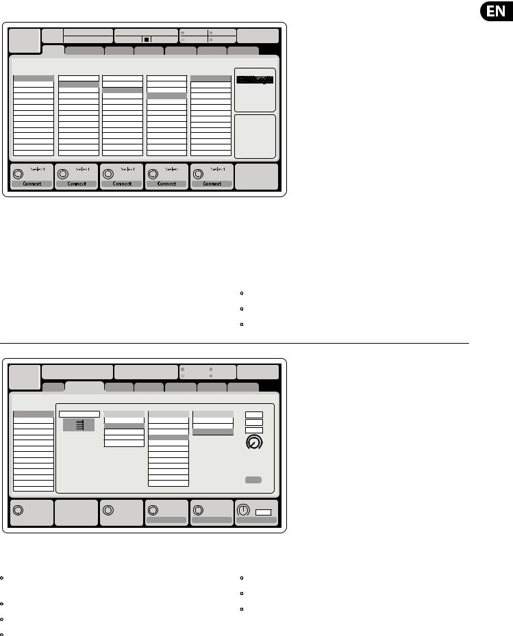
Routing I/O
The X32 RACK console features 16 analog rear-panel XLR inputs with microphone preamps, as well as 8 rear-panel XLR Outputs and 6 TRS Aux Sends and Returns.
In addition, there are two AES50 ports, each featuring 48 input and output channels, and a card slot for 32 channels of input and output to and from a connected computer via USB 2.0.
Input Signals can be attached to the console’s internal audio processing engine in blocks of 8 signals from any one of the aforementioned input sources.
Note: All signal blocks patched to the audio processing will be connected to the corresponding input channels automatically.
Local inputs 17-24 and 25-32 are listed with brackets, indicating that these are not physically available on this device. Assigning these will obviously carry no signal, but they can still be used when preparing shows for a full X32 console.
Cabling for AES50 connections between X32 and S16 stageboxes:
•Shielded Cat-5e cables only
•Ethercon terminated cable ends
•Maximum cable length 100 meters (300 feet)
Ch01 |
01 |
01: |
0:00 |
- 0:00 |
|
B: - |
|
C: X-USB 14:09 |
: 37 |
|||||||
|
|
|
|
|
|
|
|
|
|
|
A: S16 |
|
A: 48K |
|
||
|
|
analog out |
|
|
|
|
|
|
|
|
|
|
|
|
|
|
|
home |
aux out |
p16 out card out |
aes50-a aes50-b |
|
|||||||||||
|
Edit Output Assignment |
|
|
|
|
|
|
|
|
|
|
|
||||
Analog Output |
Current Setting |
|
Category |
|
|
|
Processed Output |
Signal Tap |
|
|||||||
Output 01 |
MixBus |
OFF |
OFF |
Pre EQ |
0.3 |
ft |
Output 02 |
|
Main (LRC) |
Main L |
Post EQ |
0.10 |
m |
Output 03 |
|
Mix Bus |
Main R |
Pre Fader |
||
|
0.3 |
ms |
||||
Output 04 |
|
Matrix |
Main C/M |
Post Fader |
||
Output 05 |
|
Direct Out |
Main Bus 01 |
|
|
|
Output 06 |
|
Monitor |
Main Bus 02 |
|
|
|
Output 07 |
|
|
Main Bus 03 |
|
Delay |
|
Output 08 |
|
|
Main Bus 04 |
|
|
|
|
|
|
|
|
||
*Output 09 |
|
|
Main Bus 05 |
|
|
|
*Output 10 |
|
|
Main Bus 06 |
|
|
|
*Output 11 |
|
|
Main Bus 07 |
|
|
|
*Output 12 |
|
|
Main Bus 08 |
|
Delay |
|
*Output 13 |
|
|
Main Bus 09 |
|
|
|
|
|
|
|
|
||
*Output 14 |
|
|
|
|
|
|
Select |
Select |
Select |
Select |
Delay |
0.3 ms
Assign |
Set |
Delay |
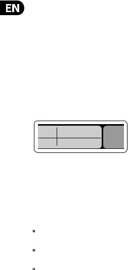
Output Signals can be freely assigned from any internal signal to any of the following outputs:
•8 analog local XLR outputs (with adjustable digital delay for time-alignment of speakers)
•8 virtual outputs (marked with *) for routing over AES50 or card outputs
•6 auxiliary sends on ¼" TRS outputs
•16 channel personal monitoring using the console’s P-16 Bus output connector
Any and all of the above signals can also be mirrored in blocks of 8 signals on either one of
•48x channels on AES50 port A
•48x channels on AES50 port B
•32x channels on USB interface card

6 |
|
X32 RACK DIGITAL MIXER User Manual |
|
|
|
|
|
|
|
|
|
|
|
|
|
|
|
|
|
|
|
||||||||||||||||
|
|
|
|
|
|
|
|
|
|
|
|
|
|
|
|
|
|
|
|
|
|
|
|
|
|
|
|
|
|
|
|
|
|
|
|
|
|
|
Ch01 |
01 |
01: |
|
|
0:00 |
|
- 0:00 |
|
|
B: - |
|
|
C: X-USB |
14:11 : 37 |
|
|||||||||||||||||||||
|
|
|
|
|
|
|
|
|
|
|
|
|
|
|
|
|
|
|
A: S16 |
|
|
A: 48K |
|
|
|
|
|
|
|
|
|||||||
|
|
|
|
|
|
home |
|
con g |
|
|
gate |
dyn |
|
|
eq |
|
|
sends |
|
|
main |
||||||||||||||||
|
|
|
|
|
|
|
|
|
|
|
|
|
|
|
|
|
|
|
|
|
|
|
|
|
|
|
|
|
|
|
|
|
|
|
|
|
|
|
|
|
|
|
|
|
|
|
|
|
|
|
|
|
|
|
|
|
|
|
|
|
|
Insert Position |
|
|
|
|
|
|
|
|
|||||
|
|
|
|
clip |
48V |
|
|
|
|
|
|
In |
|
|
|
|
t |
|
|
|
|
|
|
|
|
|
|
|
|
|
|
|
|
||||
|
|
|
|
-6 |
|
|
|
|
|
|
|
|
|
|
|
|
|
|
|
|
|
|
|
|
|
|
|
|
|
|
|
||||||
|
|
|
|
|
|
|
|
|
|
|
|
|
|
|
|
|
|
|
|
|
|
|
|
|
|
|
|
|
|
|
|||||||
|
|
|
|
-12 |
|
|
|
Reverse |
|
|
|
|
|
|
|
|
|
|
|
|
|
|
|
|
|
|
|
|
|
|
|
|
|
|
|||
|
|
|
|
-18 |
|
|
|
|
|
|
|
|
|
|
|
Delay |
|
|
|
|
|
|
|
|
|
|
|
|
|
|
|
|
|||||
|
|
|
|
|
|
|
|
|
|
|
|
|
|
|
|
|
|
|
|
|
Pre |
|
Ins |
Post |
|
||||||||||||
|
|
|
|
-24 |
|
|
|
|
|
|
|
|
|
|
|
|
|
|
|
|
|
|
|
||||||||||||||
|
|
|
|
-30 |
|
Link |
|
Lo Cut |
|
|
Source |
|
0.3 |
ft |
|
|
|
|
|
Insert |
|
||||||||||||||||
|
|
|
|
|
|
|
|
|
|
|
|
|
|||||||||||||||||||||||||
|
|
|
|
-36 |
|
|
|
OFF |
|
|
0.10 |
m |
|
|
|
|
OFF |
|
|
||||||||||||||||||
|
|
|
|
-42 |
|
+0.0 |
dB |
|
2.0 |
Hz |
Input 01 |
|
|
|
ms |
|
|
|
|
InsFX 1L |
|
|
|||||||||||||||
|
|
|
|
|
|
|
0.03 |
|
|
|
|
|
|||||||||||||||||||||||||
|
|
|
|
|
|
|
|
|
|||||||||||||||||||||||||||||
|
|
|
|
-48 |
|
|
|
|
|
|
|
|
Input 02 |
|
|
|
|
|
|
|
|
|
|
|
|
InsFX 1R |
|
|
|||||||||
|
|
|
|
|
|
|
|
|
|
|
|
|
|
|
|
|
|
|
|
|
|
|
|
|
|
|
|
|
|||||||||
|
|
|
|
-54 |
|
|
|
|
|
|
|
|
Input 03 |
|
|
|
|
|
|
|
|
|
|
|
|
InsFX 2L |
|
||||||||||
|
|
|
|
|
|
|
|
|
|
|
|
|
|
|
|
|
|
|
|
|
|
|
|
|
|
|
|
|
|||||||||
|
|
|
|
|
|
Gain |
|
Lo Cut |
|
Input 04 |
|
|
Delay |
|
|
|
|
|
|
|
|
InsFX 2R |
|
||||||||||||||
|
|
|
|
|
|
|
|
Input 05 |
|
|
|
|
|
|
|
|
|
|
InsFX 3L |
|
|
||||||||||||||||
|
|
|
|
|
|
|
|
|
|
|
|
|
Input 06 |
|
|
|
|
|
|
|
|
|
|
|
|
InsFX 3L |
|
|
|||||||||
|
|
|
|
|
|
|
|
|
|
|
|
|
|
|
|
|
|
|
|
|
|
|
|
|
|
|
|
|
|
|
|
|
|
|
|
|
|
|
|
|
|
Gain |
|
|
|
|
|
Lo Cut |
Hz |
|
|
Source |
|
|
Delay |
|
Ins Pos |
|
|
|
|
Insert |
|||||||||||||
|
|
|
|
+0.00 |
dB |
|
20 |
|
|
|
Input |
|
|
|
0.3 |
ms |
|
|
PRE |
|
|
|
|
|
InsF |
|
|||||||||||
|
|
|
Link |
|
|
|
|
Lo Cut |
|
|
|
Select |
|
Delay |
|
|
|
|
Insert |
|
Connect |
||||||||||||||||
|
|
|
|
|
|
|
|
|
|
|
|
|
|
|
|
|
|
|
|
|
|
|
|
|
|
|
|
|
|
|
|
|
|
|
|
|
|
Input Channels 1-16 are pre-configured to use the local input signals 1-16, but can be patched to use any other available signal on the audio engine as well, including mix bus/sub group outputs. Changes of the Channel Source can be made on the Preamp Config page.
Input Channels 17-32 are pre-configured to AES50 A inputs 1-16, so that connecting an S16 stage box to port A will automatically feed the channels.
Aux Return Channels 1-8 are pre-configured to use the 6 aux input signals, and the two USB playback outputs, but can be patched to use any other available signal of the console as well.
FX Return Channels 1L-4R control the 4 stereo output signals of side-chain FX1-4.
LeOnde.mp3 |
|
|
13:44:43 |
|
|
|
|
|
MyProj.prj |
|
|
|
|
|
|
|
|
|
|
|
|
00.05.00 |
00.00.00 |
|
29 November 2010 |
|
|
|
Scene01 |
|||
home |
con g |
|
gate |
dyn |
eq |
sends |
main |
|||
|
|
clip |
Bus Con guration |
|
Bus Insert Position |
||||||||
|
|
|
Channel Sends |
∑ |
|
|
|
|
|
|
|
||
|
|
-6 |
|
|
|
|
|
|
|
|
|||
|
|
-12 |
|
|
|
|
|
|
|
|
|
|
|
|
|
-18 |
|
|
|
|
|
|
|
|
|
|
|
|
|
Link |
Pre |
Insert |
Post |
||||||||
|
|
-24 |
|||||||||||
|
|
-30 |
All Channel Sends |
|
|
|
|
Insert |
|||||
|
|
|
|
|
|
||||||||
|
|
-36 |
|
|
|
|
|||||||
|
|
|
|
|
|||||||||
|
|
-42 |
Pre Con guration |
|
|
|
Ins 01 |
|
|||||
|
|
-48 |
|
... |
|
|
|
|
Ins 02 |
|
|||
|
|
|
|
|
|||||||||
|
|
-54 |
|
Inputs |
|
|
|
|
Ins 03 |
|
|||
|
|
|
Pre EQ |
|
|
|
|
Ins 04 |
|
||||
|
|
|
|
|
|||||||||
|
|
|
|
Pre Fader |
|
|
|
|
... |
|
|
|
|
|
|
|
|
Post Fader |
|
|
|
|
FX 01 |
|
|||
|
|
|
|
Sub Grou |
|
|
|
|
FX 02 |
|
|||
|
|
|
|
|
|
|
|
|
|
|
|
|
|
Gain |
Send Pos. |
Insert Pos. |
Insert |
00.00 dB |
Inputs |
Pre |
|
Link |
Bus Sends |
Insert |
Connect |
The configuration of Mix Bus Channels 1-16 can be pre-set (in the Setup/Global page) or can also be configured on an individual, per-channel basis. The bus processing includes (in this order):
•Insert point (swappable between post-EQ and pre-EQ operation)
•6-band fully parametric EQ
•Compressor/expander (swappable between post-EQ and pre-EQ operation)
•Bus sends to 6 matrices
•Main LR panning
•Mono/Center level
Main Bus Channels LR/C are always available and independent from Mix Buses. The processing steps for this signal path include (in this order):
•Insert point (swappable between post-EQ and pre-EQ operation)
•6-band fully parametric EQ
•Compressor/expander (swappable between post-EQ and pre-EQ operation)
•Bus sends to 6 matrices
Matrix Channels 1-6 are fed exclusively by MAIN LRC and Mix Bus 1-16 signals. The processing steps include (in this order):
•Insert point (swappable between post-EQ and pre-EQ operation)
•6-band fully parametric EQ
•Compressor/expander (swappable between post-EQ and pre-EQ operation)

7 X32 RACK DIGITAL MIXER User Manual
Effects Processing 1-8
The X32 RACK contains eight true-stereo internal effects engines.
•FX 1-4 can be configured as side chain or insert effects, while FX 5-8 can only be used in insert points of channels or buses
•The FX Home screen allows selection of the FX 1-4 input sources and selecting the effects type/algorithm for each of the 8 FX slots of the virtual rack
•The subsequent tabs FX 1-FX 8 of the FX screen allow editing all parameters of the chosen effects processor
iPad App for X32 RACK
Many functions of the X32 RACK console can be remotely controlled by a dedicated iPad app.
The app’s User Interface is optimized for the touchscreen nature of the iPad device and concentrates on the most important remote features of the console only. Using the app, you can perform functions such as adjusting monitor mixes from the stage while interacting with musicians, or adjusting the front-of-house mix from the audience, while hearing the mix exactly as the audience does.
Linux/OS X applications and Windows-based applications for X32 RACK
Also offered is a separate remote editor running on host computers that will allow for complete editing control of the X32 RACK via Ethernet.
Tip: The X32 RACK remote communication is OSC-based (open sound control) and we will share the protocol on our website, allowing developers to design their own control software. Stay tuned to behringer.com for details on the OSC protocol.
X-USB expansion card
The X-USB card allows transmission of up to 32 channels to and from a connected computer. Please download the X-USB drivers and Quick Start Guide from behringer.com before connecting the mixer to your computer. The card is CoreAudio compatible, allowing it to work with computers with the OS X operating system software of Apple, Inc. without a driver.
Ch01 |
01 02: next |
0:00 |
- 0:00 |
B: - |
C: X-USB |
15:33: 15 |
OpeningScene |
|
|
A: S16 |
A: 48K |
|
|
FatSnare |
home con g |
gate |
dyn |
eq |
sends |
main |
Main Display Area |
|
|
|
|
Customizing the X32 RACK through the Utilities page |
|
The top section of the main display permanently covers useful status information. The top left corner shows the selected channel number,
its nickname and the selected icon. The next block shows the current scene number and name in amber, as well as the next upcoming scene. The center section displays the playback file name along with elapsed and remaining time and a recorder status icon. The next block to the right has 4 segments to show the status of AES50 ports A and B, the Card slot and the audio clock
synchronization source and sample rate (top right). Small green square indicators show proper connectivity. The right most block shows the console time that can be set under Setup/Config.
When working with any given screen, press the Page keys located on the display bezel to switch to different screen pages.
Editing parameters or settings on each of the screens is done using the 6 associated push-encoders along the bottom edge of the display.
•Whenever there is a continuous control or list entry, you can turn the corresponding knob for editing, which is indicated by various circular icons
•When there is a switch or toggle function on one of these knobs, you will see a broad rectangular button along the lower edge of the field. Pressing the encoder changes the on/off state of the corresponding function. When the rectangular button in the display is dark grey, the corresponding function is off/inactive; when it is amber, the function is on/active
Press the Utility button, located to the right of the main display, to bring up useful functions in a “context-sensitive” manner. For example:
•When you are adjusting the equalizer of a console channel, pressing the Utility button will offer copying, pasting, loading or saving of equalizer settings
•On the Routing pages, pressing the Utility button will offer loading or saving different presets of routing scenarios
•In the Scenes menu, pressing the Utility button offers copying, loading, saving or naming console scenes
NOTE: The X32 RACK DCA groups can be selected using the Channel Select control in order to adjust their fader level, mute or solo status. Note, however, that the main display will remain focused on the last real channel (bus or input) that was selected before DCA, since DCAs do not feature any processing.
8 X32 RACK DIGITAL MIXER User Manual
Startup and Shutdown, and Update:
We recommend switching the X32 RACK mixer on first, and shutting it off last when any sound system is connected. This will prevent the possibility of any unexpected noises being transmitted during the startup/shutdown process.
The Setup screen’s general preference page contains a Safe Main Levels function. When activated, the console automatically mutes the main LRC levels when booting the console. It also prevents any scene loading from affecting (i.e. turning up)
the mains levels.
Synchronization and Sample Rate settings for the console can be adjusted on the Setup/Config page, but please note that sample rate changes will require a reboot of the console. When you see a red square indication at the top section of the main display, please verify if the synchronization settings on Setup/Config make sense.
16  A 48K 15
 C X-USB
In order to prevent any errors by losing power during a store operation,
we recommend using the “Safe Shutdown” function from the Setup/Global page.
NOTE: The X32 RACK can be locked against unintended use by activating ‘Lock Console’ from the Setup/Global page. In this state the UI will not allow any changes to be made and the display shows “X”. Keep HOME depressed for about 5 seconds to unlock the X32 again.
The X32 firmware can easily be updated by performing the following steps:
•Download the new console firmware from the X32 RACK product page onto the root level of a USB thumb drive
•Plug the USB thumb drive into the front panel USB connector while the console is turned off
•Hold the USB button depressed while switching the console on. While booting, the X32 RACK will run a fully automatic firmware update, which will take
2-3 minutes longer than the regular boot sequence
When no update file is available on the USB drive, or when it is corrupted,
the update mode will remain active, preventing the X32 from booting regularly. Switch the console off and back on without holding the USB button to boot the console with the existing firmware.
CAUTION: Please do not block the vent openings on the sides of the X32 RACK cabinet! Specifically when mounting the X32 RACK in a road case, please ensure there is sufficient space to allow for some airflow.
9X32 RACK DIGITAL MIXER User Manual
2.Callouts
(1) |
(3) (4) |
(5) |
(6) |
(10) |
(11) |
(13) (10) |
|
(16) |
(17) |
|
|
|
(21) |
||||||||||
|
|
|
|
|
|
|
|
|
|
|
|
|
|
|
|
|
|
|
|
|
|
|
|
|
|
|
|
|
|
|
|
|
|
|
|
|
|
|
|
|
|
|
|
|
|
|
|
|
|
|
|
|
|
|
|
|
|
|
|
|
|
|
|
|
|
|
|
|
|
|
|
|
|
|
|
|
|
|
|
|
|
|
|
|
|
|
|
|
|
|
|
|
|
|
|
|
|
|
|
|
|
|
|
|
|
|
|
|
|
|
|
|
|
|
|
|
|
|
|
|
|
|
|
|
|
|
|
|
|
|
|
|
|
|
|
|
|
|
|
|
|
|
|
|
|
|
|
|
|
|
|
|
|
|
|
|
|
|
|
|
|
|
|
|
|
|
|
|
|
|
|
|
|
|
|
|
|
|
|
|
|
|
|
|
|
|
|
|
|
|
|
|
|
|
|
|
|
|
|
|
|
|
|
|
|
|
|
|
|
|
|
|
|
|
|
|
|
|
|
|
|
|
|
|
|
|
|
|
|
|
|
|
|
|
|
|
|
|
|
|
|
|
|
|
|
|
|
|
|
|
|
|
|
|
|
|
|
|
|
|
|
|
|
|
|
|
|
|
|
|
|
|
|
|
|
|
|
|
|
|
|
|
|
|
|
|
|
|
|
|
|
|
|
|
|
|
|
|
|
|
|
|
|
|
|
|
|
|
|
|
|
|
|
|
|
|
|
|
|
|
|
|
|
|
|
|
|
|
|
|
|
|
|
|
|
|
|
|
|
|
|
|
|
|
|
|
|
|
|
|
|
|
|
|
|
|
|
|
|
|
|
|
|
|
|
|
|
|
|
|
|
|
|
|
|
|
|
|
|
|
|
|
|
|
|
|
|
|
|
|
|
|
|
|
|
|
|
|
|
|
|
|
|
|
|
|
|
|
|
|
|
|
|
|
|
|
|
|
|
|
|
|
|
|
|
|
|
|
|
|
|
|
|
|
|
|
|
|
|
|
|
|
|
|
|
|
|
|
|
|
|
|
|
|
|
|
|
|
|
|
|
|
|
|
|
|
|
|
|
|
|
|
|
|
|
|
|
|
|
(2) |
(7) |
(8) |
(9) |
(12) |
(14) |
(15) |
(19) |
(18) |
(20) |
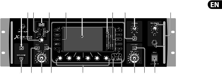
(1)USB button opens the Recorder View on the MAIN DISPLAY, causing the LED to glow green. The LED will glow red to indicate access on the DATA/AUDIO input. An unlit LED indicates no data access and inactive Recorder View.
(2)DATA/AUDIO USB input allows connection of USB flashdrives for firmware updates, loading/saving scenes and show files, and playing back or recording WAV files.
(3)CHANNEL SELECT control cycles through all channels by turning the knob. By pressing this knob, you can jump to the next type of channels.
(4)CHANNEL TYPE LEDs indicate which type of channel is currently selected.
(5)CHANNEL NUMBER display shows the currently selected channel.
(6)INPUT METER displays the pre-fader input level of the selected channel.
(7)SOLO button routes the currently selected channel to the monitoring paths. The LED lights when active.
(8)CHANNEL LEVEL control adjusts the currently selected channel’s output.
(9)MUTE button mutes the currently selected channel. The LED lights when active.
(10)MAIN MENU buttons open specific menus on the MAIN DISPLAY.
(11)MAIN DISPLAY shows permanent information about the mixer’s configuration as well as information about the currently selected menu.
(12)DISPLAY ENCODER knobs allow adjustment and on/off selection of the menu items indicated at the bottom of the MAIN DISPLAY.
(13)MAIN METER indicates the Main Mono or SOLO level in the left meter and the Main Stereo level on the right.
(14)PAGE SELECT buttons curse horizontally in the MAIN DISPLAY and make Yes / No confirmations.
(15)LAYER SELECT buttons access different parameter layers that can be edited by the DISPLAY ENCODERS.
(16)TALK button engages the Talkback microphone. Routing is defined in the Monitoring Preferences page.
(17)TALK LEVEL knob sets the Talkback mic gain.
(18)CLEAR SOLO button lights to indicate that one of the channels has been Soloed. Press to deactivate all active solo functions.
(19)MAIN LR LEVEL knob adjusts the main stereo output bus.
(20)ON/OFF button turns the power on and off.
(21)MONITOR LEVEL knob adjusts the headphone and monitor output volume. Connect headphones to the 1" front panel input.
10 X32 RACK DIGITAL MIXER User Manual |
|
|
|
|
||
(22) |
(23) |
(24) |
|
|
|
(31) |
(25) |
|
|
|
|
|
|
|
|
(26) |
(27) |
(28) |
(29) |
(30) |
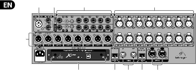
(22)TALKBACK input connects a talkback microphone via XLR cable.
(23)MONITOR outputs send audio to monitor speakers via 1" balanced cables.
(24)AUX IN and OUT jacks send and receive signals via 1" and RCA connectors.
(25)XLR OUT jacks send audio via XLR cable. Output signals are configured on the Routing/Aux Out page of the MAIN DISPLAY.
(26)X-USB card provides 32 channels of input and output via USB cable to and from any connected personal computer DAW application.
(27)ETHERNET connector allows full OSC-based remote control of the X32 RACK.
(28)MIDI IN/OUT allows the unit to send and receive MIDI commands via standard 5-pin DIN cables.
(29)ULTRANET connector sends 16 channels of audio to a P16 monitoring system.
(30)AES50 A and B connectors allow 96 channels of bidirectional audio for connection to S16 digital snakes or other X32 family products. Shielded CAT-5e cable should always be used for AES50 connections between X32 and S16 units.
(31)XLR IN jacks receive inputs via XLR cable. These inputs feature 16 MIDASdesigned mic/line preamps with 72 dB of gain range. Each input has an adjacent red LED to indicate when 48 V phantom power supply is engaged.

11X32 RACK DIGITAL MIXER User Manual
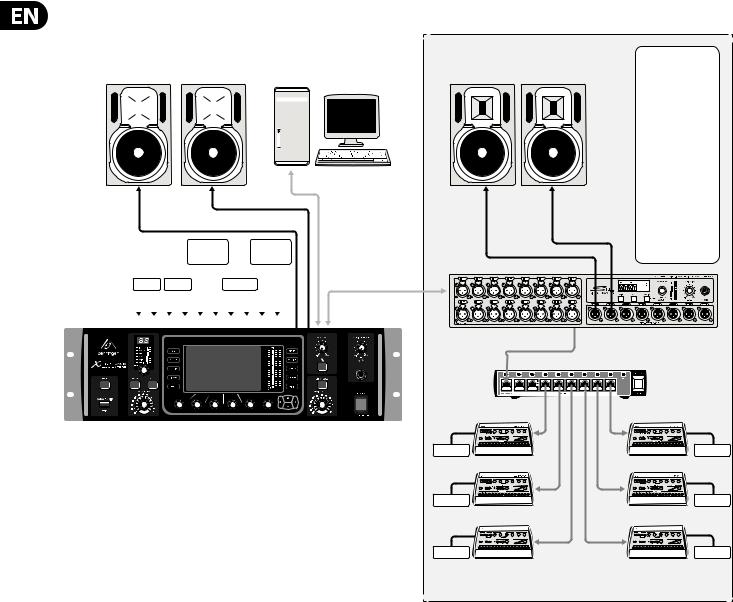
3.Hookup
X32 RACK Live Performance Setup with S16, X32, and P16 Monitor System
Digital cable (CAT5)
Analog Cable
AES50 Out 1-16 |
AES50 |
Phones |
|
P16 Bus signals |
CH 1-32 In |
||
|
|||
|
|
|
X32 RACK Out 1-8 for FOH amps/loudspeakers, front and side lls,
or stage monitoring on the left
AES50 |
CH 1-16 In |
CH 17-32 In |
|
S16 Out 1-8 for FOH amps/loudspeakers, front and side lls or stage monitoring on the right
P16-D Distributor |
|
|
|
|
P16-D Distributor |
IEM |
|
IEM |
IEM |
|
IEM |
Bass Player |
Vocal 1 |
|
2nd Guitarist |
|
Background Vocal 2 |
IEM |
|
|
IEM |
|
IEM |
Guitarist |
Keyboardist |
|
Background Vocal 1 |
Background Vocal 3 |
|
Phones |
|
|
|
|
IEM |
Drummer |
Voc 1 |
|
Percussionist |
|
Spare |
POWERPLAY P16-M |
Floor wedges |
|
|
|
|
|
|
|
|
|
|
Digital Personal Mixers |
|
|
|
|
|
|
Vocal 1 |
|
Keyboards |
Percussion |
|
F1320D Active oor monitors
12 X32 RACK DIGITAL MIXER User Manual
X32 RACK Recording Studio Setup
Control Room
B3031A Studio Monitors |
Computer tower with DAW software |
|
|
|
|
|
|
|
|
|
|
|
|
|
|
|
|
|
|
|
|
|
|
|
|
|
|
|
|
|
|
|
|
|
|
|
|
|
|
|
|
|
|
|
|
|
|
|
|
|
|
|
|
|
|
|
|
|
|
|
|
|
|
|
|
|
|
|
|
|
|
|
|
|
|
|
|
|
|
|
|
|
|
|
|
|
|
|
|
|
|
|
|
|
|
|
L |
|
|
|
|
|
|
R |
|
|
|
|
|
|
|
|
|
|
|
|
|
|
||||
|
|
|
|
|
|
|
|
|
|
|
|
|
|
|
|
|
|
|
|
|
|
|
|
||||||
|
|
|
|
|
|
|
|
|
|
|
|
|
|
|
|
|
|
|
|
|
|
|
|
||||||
|
|
|
|
|
|
|
|
|
|
|
|
|
|
|
|
|
|
|
|
|
|
|
|
||||||
|
|
|
|
|
|
|
Monitor/Control Room Out |
|
|
|
|
|
USB cable |
||||||||||||||||
|
|
|
|
|
|
|
|
|
|
|
|
|
|
|
|
|
|
|
|
|
|
|
|
|
|
|
|||
|
|
|
|
|
|
|
|
|
|
Rack |
|
|
|
|
Outboard |
|
|
|
|
|
from X-USB |
||||||||
|
|
|
|
|
|
|
|
|
|
|
|
|
|
|
|
|
|
|
interface card |
||||||||||
|
|
|
|
|
|
|
|
|
|
Expander |
|
|
FX |
|
|
|
|
|
|
|
|
|
|
|
|||||
|
|
Keys 1 |
Keys 2 |
|
|
Sampler |
|
|
|
|
|
|
|
|
|
|
|
|
|||||||||||
|
|
L |
|
R |
|
L |
R |
L |
R |
L |
|
R |
L |
R |
|
|
|
|
|
|
|
|
|
AES50 cable |
|||||
|
|
|
|
|
|
|
|
|
|
|
|
|
|
|
|
|
|
|
|
|
|
|
|
|
|
|
|
|
|
|
|
1 |
2 |
3 |
4 |
5 |
6 |
7 |
8 |
9 |
10 |
|
|
|
|
|
|
|
|
|
|
||||||||
|
|
|
|
|
|
|
|
|
|
|
|
|
|
|
|
|
|
|
|
|
|
|
|
|
|
|
|
|
|
|
|
|
|
|
|
|
|
|
|
|
|
|
|
|
|
|
|
|
|
|
|
|
|
|
|
|
|
|
|
|
|
|
|
|
|
|
|
|
|
|
|
|
|
|
|
|
|
|
|
|
|
|
|
|
|
|
|
|
|
|
|
|
|
|
|
|
|
|
|
|
|
|
|
|
|
|
|
|
|
|
|
|
|
|
|
|
|
|
|
|
|
|
|
|
|
|
|
|
|
|
|
|
|
|
|
|
|
|
|
|
|
|
|
|
|
|
|
|
|
|
|
|
|
|
|
|
|
|
|
|
|
|
|
|
|
|
|
|
|
|
|
|
|
|
|
|
|
|
|
|
|
|
|
|
|
|
|
|
|
|
|
|
|
|
|
|
|
|
|
|
|
|
|
|
|
|
|
|
|
|
|
|
|
|
|
|
|
|
|
|
|
|
|
|
|
|
|
|
|
|
|
|
|
|
|
|
|
|
|
|
|
|
|
|
|
|
|
|
|
|
|
|
|
|
|
|
|
|
|
|
|
|
|
|
|
|
|
|
|
|
|
|
|
|
|
|
|
|
|
|
|
|
|
|
|
|
|
|
|
|
|
|
|
|
|
|
|
|
|
|
|
|
|
|
|
|
|
|
|
|
|
|
|
|
|
|
|
|
|
|
|
|
|
|
|
|
|
|
|
|
|
|
|
|
|
|
|
|
|
|
|
|
|
|
|
|
|
|
|
|
|
|
|
|
|
|
|
|
|
|
|
|
|
|
|
|
|
|
|
|
|
|
|
|
|
|
|
|
|
|
|
|
|
|
|
|
|
|
|
Recording Room
|
S16 Input List |
B3031A Studio Monitors |
1. Lead Vocal |
|
2. Vocal 2 |
|
3. Vocal 3 |
|
4. Vocal 4 |
|
5. Vocal 5 |
|
6. Acoustic Guitar |
|
7. Rhythm E. |
|
Guitar |
|
8. Lead E. Guitar |
|
9. E. Bass (via DI) |
|
10. Kick |
|
11. Snare |
|
12. Tom 1 |
|
13. Tom 2 |
|
14. Floor Tom |
|
15. Overhead 1 |
|
16. Overhead 2 |
DIGITAL SNAKE S16 |
|
|
P16-D Distributor |
Phones |
Phones |
Phones |
Phones |
Phones |
Phones |
POWERPLAY P16-M |
|
Personal Monitor Mixers |
|
13X32 RACK DIGITAL MIXER User Manual
4.FX Descriptions
FX Descriptions
Here is a list and brief description of the effects available on the X32 RACK. When Stereo and Dual versions of an effect are offered, use the Stereo version when the left and right signal are to be altered together (e.g. on linked stereo channels or buses), or Dual when you want to dial different settings for the left and right signal. See the Topic Guide for instructions on how to add effects to a channel or bus.
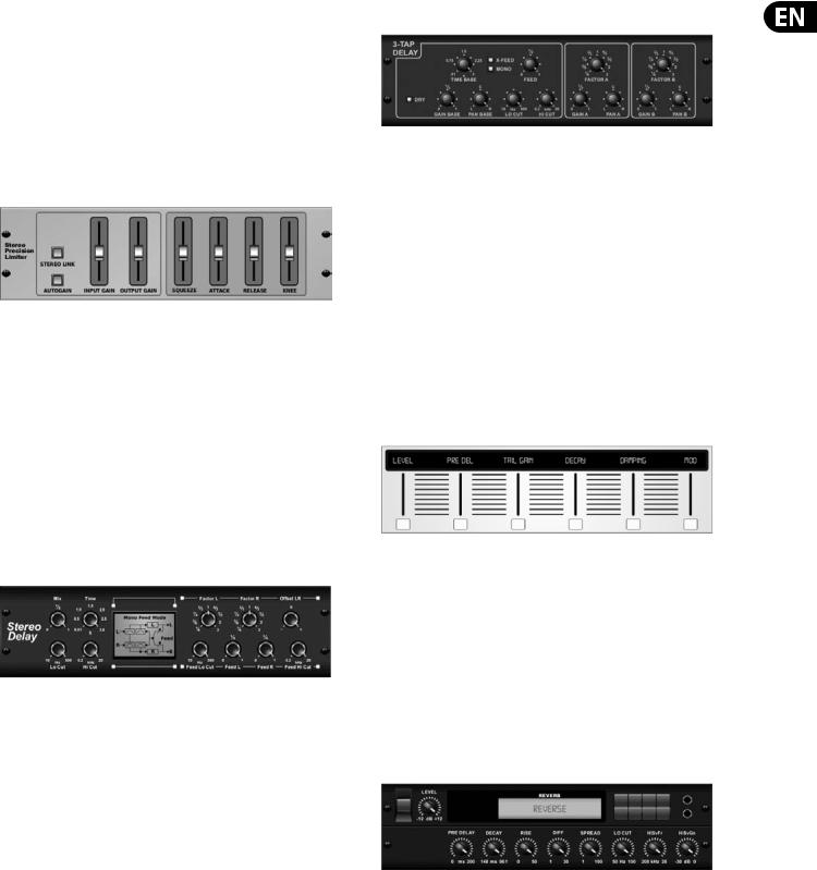
Stereo Precision Limiter
Stereo Precision Limiter allows you to set a precise volume limit,
ensuring distortion-free, optimal signal integrity. Use X32’s Stereo Precision Limiter to boost quiet signals or preventing clipping while preserving the level of “hot” signals.
AUTOGAIN activates an additional long-term gain correction, allowing automatic gain scaling of varying input level ranges. STEREO LINK applies limiting to both channels equally when activated. INPUT GAIN provides up to 18 dB of gain to the input signal prior to limiting. OUTPUT GAIN sets the final gain level of the processed signal. SQUEEZE adds compression to the signal to add punch and a slight distortion depending on the amount you dial in. ATTACK sets the attack time, ranging from 0.05 mS to 1 mS. RELEASE adjusts the release time from
0.05 mS to 1.04 seconds. KNEE adjusts the soft limiting threshold point from hard limiting (0 dB) to maximum soft limiting (10 dB).
Stereo Delay
Stereo Delay provides independent control of left and right delay (echo) times and features high and low pass filters for enhanced tone shaping of the
delayed signals. Use the Stereo Delay to give your mono signals a wide presence in the stereo field.
The MIX control lets you blend the source signal and the delayed signal.
TIME adjusts the master delay time up to three seconds. LO CUT adjusts the low frequency cut, allowing lower frequencies to remain unaffected by the delay. HI CUT adjusts the high frequency cut, allowing higher frequencies to remain unaffected by the delay. FACTOR L sets the delay on the left channel to rhythmic fractions of the master delay time. FACTOR R sets the delay on the right channel
to rhythmic fractions of the master delay time. OFFSET LR adds a delay difference between the left and right delayed signals. The FEED LO CUT/HI CUT adjusts filters in the feedback paths. FEED L and FEED R control the amount of feedback for
the left and right channels. MODE sets the feedback mode: Mode ST sets normal feedback for both channels, X crosses feedbacks between left and right channels. M creates a mono mix within the feedback chain.
Triple Delay
Sometimes called a 3-Tap Delay, the Triple Delay provides three delay stages with independent frequency, gain, and pan controls. Create time-based echo effects with the Triple Delay to increase the sense of stereo separation.
TIME BASE sets the master delay time, which is also the delay time for the first stage. GAIN BASE sets the gain level of the first stage of the delay. PAN BASE sets the position of the first delay stage in the stereo field. LO CUT sets the frequency at which the source signal can begin passing through the delay. HI CUT sets the frequency at which the source signal no longer passes through the delay. X-FEED indicates that stereo cross-feedback of the delays is active. MONO activates a mono mix of both channels for the delay input. FEED adjusts the amount of feedback. FACTOR A controls the amount of delay time in the second stage of the delay. GAIN A controls the gain level of the second delay stage. PAN A sets the position of the second delay stage in the stereo field. FACTOR B controls the amount of delay time in the third stage of the delay. GAIN B controls the gain level of the third delay stage. PAN B sets the position of the third gain stage in the stereo field.
Ambience
Ambience creates a customizable virtual acoustic space in which to place the elements of a mix. Use Ambience to add warmth and depth without coloring the direct sound. (Inspired by the Lexicon Ambience Algorithm)
PRE DELAY sets the time before the reverb follows the source signal. DECAY adjusts the time it takes for the reverb to completely dissipate. SIZE controls the room size emulation. DAMPING controls the high frequency decay within the reverb tail. DIFFUSE controls the initial echo density. Level sets the volume output of the affected signal. LO CUT adjusts the low frequency cut, allowing lower frequencies to remain unaffected by the reverb. HI CUT adjusts the high frequency cut, allowing higher frequencies to remain unaffected by the reverb. MOD adjusts the level of reverb decay modulation. TAIL GAIN adjusts the volume of the reverb tail.
Reverse Reverb
Reverse Reverb takes the trail of a reverb, turns it around, and places it in front of the sound source. Use the swelling crescendo of the Reverse Reverb to add an ethereal quality to vocal and snare tracks. (Inspired by the Lexicon 300/480L)
Adjusting the PRE DELAY knob adds up to 200 milliseconds of time before the reverb follows the source signal. The DECAY knob adjusts the time it takes for the reverb to completely dissipate. RISE controls how quickly the effect builds up. DIFF(USION) controls the initial reflection density. SPREAD controls how the reflection is distributed through the envelope of the reverb. The LO CUT knob sets
a low frequency beneath which the source signal will not pass through the reverb. The HiSvFr/HiSvGn knobs adjust a Hi-Shelving filter at the input of the reverb effect.
14 X32 RACK DIGITAL MIXER User Manual
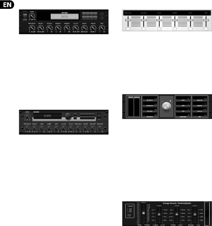
Gated Reverb |
Hall Reverb |
This effect was originally achieved by combining a reverb with a noise gate.
Our gated reverb creates the same impression by a special shaping of the reverb tail.
Gated Reverb is especially effective for creating a 1980s-style snare sound or to enlarge the presence of a kick drum. (Inspired by the Lexicon 300/480L)
PRE DELAY controls the amount of time before the reverberation is heard following the source signal. DECAY controls the amount of time it takes for the reverb to dissipate. ATTACK controls how fast the reflection density builds up. DENSITY shapes the reverb decay tail. The higher the density, the greater the number of sound reflections. SPREAD controls how the reflection is distributed through the envelope of the reverb. The LO CUT knob sets the frequency beneath which the source signal will not pass through the reverb. The HiSvFr/ HiSvGn knobs adjust a Hi-Shelving filter at the input of the reverb effect. DIFF(USION) controls the initial reflection density.
Plate Reverb
A plate reverb was originally created by sending a signal through a transducer to create vibrations on a plate of sheet metal which were then picked up as an audio signal. Our algorithm simulates that sound with high initial diffusion and a bright colored sound. X32’s Plate Reverb will give your tracks the sound heard on countless hit records since the late 1950s. (Inspired by the Lexicon PCM-70)
PRE DELAY controls the amount of time before the reverberation is heard following the source signal. DECAY controls the amount of time it takes for the reverb to dissipate. SIZE adjusts the size of the virtual room created by the reverb effect. The DAMP knob adjusts the decay of high frequencies within the reverb tail. DIFF(USION) controls the initial reflection density. The LO CUT knob sets the frequency beneath which the source signal will not pass through the reverb. The HI CUT knob sets the frequency above which the source signal will not pass through the reverb. The BASS MULT(IPLIER) knob adjusts the decay time of the bass frequencies. XOVER controls the crossover point for bass. MOD DEPTH and SPEED control the intensity and speed of the reverb tail modulation.
Classic Hall Reverb simulates the reverberation that occurs w hen sound is recorded in medium to large-sized concert halls. Use the Hall Reverb to give your mix a lush, three-dimensional quality that will make your performance sound larger than life. (Inspired by the Lexicon Hall)
The PRE DELAY slider controls the amount of time before the reverberation is heard following the source signal. DECAY controls the amount of time it takes for the reverb to dissipate. SIZE controls the perceived size of the space being created by the reverb effect. The DAMP slider adjusts the decay of high frequencies within the reverb tail. DIFF(usion) controls the initial reflection density. SHAPE adjusts the contour of the reverberation envelope.
Vintage Room
Vintage Room simulates the reverberation that occurs when sound is recorded in a small room. When you want to add a bit of warmth and just a touch of reverb, X32’s Vintage Room breathes life into close-miced guitar and drum tracks. (Inspired by the Quantec QRS)
The VU meter displays the input and output levels. Set the early reflection times for the left and right channel with ER DELAY L and ER DELAY R. ER LEVEL sets the loudness of the early reflection level. REV DELAY controls the amount of time before
the reverberation is heard following the source signal. HI/LOW MULTIPLY adjusts the decay time of the high and bass frequencies. TIME shows the duration of the reverb effect. ROOM SIZE adjusts the size of the room effect being created incrementally from small to large. HIGH CUT sets the frequency above which the source signal does not pass through the reverb. DENSITY manipulates the reflection density in the simulated room. (This slightly changes the reverb decay time). LOW CUT sets the frequency below which the source signal does not pass through the reverb.
Vintage Reverb
Based on the legendary EMT250, X32’s Vintage Reverb delivers shimmering bright reverb that won’t drown out or overpower your live or recorded tracks. Use Vintage Reverb to sweeten vocals and snare drums without sacrificing clarity.
When layer 1 is selected, the first slider on the left sets the reverb time from 4 milliseconds to 4.5 seconds. Slider 2 controls the low frequency multiplier
decay time. Slider 3 controls the high frequency multiplier decay time. Slider 4 controls the amount of modulation in the reverb tail. When layer two is selected, slider 1 adjusts the pre delay. Slider 2 selects the low cut frequency. Slider 3 selects the Hi Cut frequency. Slider 4 adjusts the output level of the reverb.

15 X32 RACK DIGITAL MIXER User Manual
When Layer 1 is selected, the far left encoder push button allows you to select between virtual front and rear outputs. Rear is suitable for drums due to it being less reflective. Front is well-suited for vocals and other dynamic instruments. The Vintage button enables the simulation of the input transformers.
Stereo/Dual Tube Stage/Overdrive
Tube Stage/Overdrive is a versatile effect capable of emulating a variety of modern and classic tube preamps. Available in stereo and dual-mono versions, use Tube Stage/Overdrive to dial in warm and fuzzy sounds from subtle to fully saturated.
DRIVE adjusts the amount of harmonics being driven by the effect. EVEN and ODD adjust the amount of even and odd harmonics. GAIN adjusts the output gain of the effect. LO CUT sets the input frequency below which the source signal will not pass through the effect. HI CUT sets the input frequency above which the input signal will not pass through the effect. BASS GAIN/FREQ adjust a low shelving filter at the output of the effect. TREBLE GAIN/FREQ adjust a high shelving filter at the output of the effect.
Stereo Imager
Chorus / Stereo Chorus
Chorus samples the input, slightly detunes it and mixes it with the original signal to produce a somewhat thicker, shimmering sound. Use it to thicken up background vocals, or to double the sound of brass and woodwind instruments.
Where as DELAY L/R set the total amount of delay for the left and right channel, WIDTH determines the amount of modulated delay. SPEED sets the modulation speed. MIX adjusts the balance of the dry and wet signals. You can further sculpt the sound by trimming some of the low and high end from the effected signal with the LO and HI CUT knobs. Additionally, the PHASE knob can tweak the phase offset of the LFO between left and right channel and the SPREAD knob adjusts how much of the left channel is mixed into the right and vice versa. Finally, the WAVE knob blends between the “Danish-style” digital triangular chorus sound and the classic analog sine wave.
Flanger / Stereo Flanger
A Stereo Imager is typically used to control the placement of a signal within the stereo field during mixdown or mastering. Modeled after the BEHRINGER Edison rack unit, X32’s Stereo Imager will lend a professional quality to your live and recording performances.
The BALANCE knob allows you to emphasize the mono or stereo components of the input signal. The mono and stereo signals can be panned independently
with the MONO PAN and STEREO PAN knobs. OUT GAIN is used to compensate for level changes resulting from the effect. The phase can also be shifted using the shelving knobs. Select the frequency and bandwidth (Q) using the corresponding knobs, then adjust the gain with the SHV GAIN knob.
Rotary Speaker
Rotary Speaker emulates the sound of a Leslie rotating speaker. X32’s Rotary Speaker provides more flexibility than its electro-mechanical counterpart, and can be used with a variety of instruments, and even vocals, to create a whirling, psychedelic effect.
The LO SPEED and HI SPEED knobs adjust the rotational speed of the SLOW and FAST Speed selection, and can be toggled with the FAST button.
The ACCEL(eration) knob adjusts how quickly the speed increases and decreases from the Slow mode to the Fast mode. The rotation effect can also be disengaged with the STOP button, which will stop the movement of the speakers.
DISTANCE adjusts the distance between the Rotary speakers and the virtual microphone.
The Flanger emulates the phase-shifting sound (comb-filtering)
originally created by applying pressure against the flange of the reel on a tape recorder. This effect creates a unique “wobbly” sound that is quite dramatic when used on vocals and instruments.
The controls of this effect are nearly identical to the Chorus effect block. Additionally, the FEEDBACK can be adjusted with positive and negative amounts and also band-limited with the FEED HC (high-cut) and FEED LC (low-cut) knobs.
Stereo Phaser
A Stereo Phaser, or phase shifter, applies multiple STAGES of modulated filters to the input signal to create a “notch” in the frequency response, and then applies a MIX with the original for a “swirling” effect. Use X32’s Stereo Phaser to add a “spaced-out” sound to vocal or instrument tracks.
SPEED adjusts the LFO rate and DEPTH sets the LFO modulation depth.
The BASE knob adjusts the frequency range of the modulated filters.
The resonance is adjusted with the RESO knob. The WAVE knob shapes the symmetry of the LFO waveform and PHASE dials in an LFO phase difference between the left and right channel. The modulation source can also be the signal envelope, which produces vowel-like opening and closing tones. The ENV MOD knob adjusts how much this effect takes place (positive and negative modulation is possible), and the ATTACK, HOLD and RELEASE knobs all tailor the response of this feature.

16 X32 RACK DIGITAL MIXER User Manual
Tremolo / Panner |
Wave Designer |
Stereo Tremolo creates an up and down volume change at a constant and even tempo just like the guitar amps of yesteryear. Use X32’s Stereo Tremolo to add a unique “surf-music” texture to a vocal or instrument track.
SPEED adjusts the LFO rate and DEPTH sets the amount of modulation. PHASE can be used to set an LFO phase difference between the left and right
channel, which can be used for panning effects. The WAVE knob blends the LFO waveform between triangular and square shape. The signal envelope, shaped by ATTACK, HOLD and RELEASE, can be used to modulate the LFO speed (ENV SPEED) and the LFO modulation depth (ENV DEPTH).
Stereo / Dual Pitch
Pitch shifting is often used in two different ways. One is to set the Mix knob lower and only use the Cent knob to make a small offset in pitch between the wet and dry tones. This results in a “voice doubling” effect that thickens the overall sound in a more subtle way. The extreme use of the effect is to turn the Mix knob fullyclockwise so the entire signal is effected. This way, the signal can be shifted into other keys up to an octave above or below the original. When used on a voice, this results in a “chipmunk” sound or a low Darth Vader effect.
When the SEMI and CENT knobs are set at 12:00, the pitch is not altered. Making adjustments by semitone will have a very pronounced effect,
whereas changes to the CENT knob will be very minor. The DELAY knob creates a time difference between the wet and dry sound. The LO and HI CUT knobs allow the effected signal to be band-limited. The Dual Pitch effect allows the left and right channels to be adjusted independently, and allows GAIN compensation and panning of the two channels.
Stereo / Dual Guitar Amp
Modeled after the Tech 21 SansAmp, the Stereo / Dual Guitar Amp simulates the sound of plugging into a real guitar amp. From shimmering cleans to saturated crunch, X32’s Stereo / Dual Guitar Amp allows an electric guitar player to sound great without using an amp on stage.
The PREAMP knob adjusts the amount of input gain prior to the band-specific distortion adjustment. BUZZ adjusts the low-end breakup, PUNCH adjusts the midrange distortion, and CRUNCH tailors the high-frequency content and distortion for smooth or cutting notes. The DRIVE knob simulates the amount of power amp distortion from a tube amp. The LOW and HIGH knobs allow EQ adjustment independent of distortion content, and the overall output is controlled by the LEVEL knob. The CABINET simulation can be bypassed if the guitarist is already using a real cab, which allows the effect to function like a
boost or distortion pedal. The Dual Guitar Amp allows the left and right channels to be adjusted independently.
Wave Designer is a powerful tool for adjusting signal transients and dynamics, such as attack and sustain. Use it to make a snare drum really “crack” in the mix or level out volume inconsistencies of slap bass tracks. (Inspired by the SPL Transient Designer)
Adjusting the ATTACK knob can add punch or tame overly dynamic signals. Increasing the SUSTAIN knob acts in a similar way as a compressor, allowing the peaks to carry longer before decay. The effect can also be used to reduce the sustain for a more staccato sound. The GAIN knob compensates for level changes caused by the effect.
Stereo Exciter / Dual Exciter
Exciters increase presence and intelligibility in live sound applications, and are indispensable for adding clarity, air and harmonic overtones in the recording studio. This effect is particularly useful for filling out the sound in difficult rooms and for producing a more natural live/recorded sound. (Inspired by the famous Aphex Aural Exciter)
Set the frequency of the side-chain filter with the TUNE knob, and further shape the filter slope with the PEAK and ZERO FILL knobs. Turning the TIMBRE knob left of center adds more odd harmonics, while turning it right of center adds more even harmonics. Adjust the harmonic content added to the signal with the HARMONICS knob, and blend in the effected signal with the MIX knob. Engage the SOLO MODE to isolate only the audio resulting from the effect so you can hear exactly what you’re adding to the mix.
Stereo Enhancer / Dual Enhancer
X32’s Enhancers are so called “Psycho EQs”. They can enhance the signal spectrum in bass, midrange and high frequencies but they differ from traditional equalizers. When you need to generate maximum punch, clarity and detail, without turning up the overall volume, our enhancers are the solution.
(Inspired by the SPL Vitalizer)
Adjust the BASS, MID and HI GAIN knobs to add or reduce content in those spectrums. The BASS and HI FREQuencies can be specifically selected, while the MID Q (bandwidth) can be adjusted instead. The OUT GAIN knob compensates for changes in level resulting from the effect, and the SPREAD knob (Stereo version only) emphasizes the stereo content for a wider mix. Engage the SOLO MODE
to isolate only the audio resulting from the effect so you can hear exactly what you’re adding to the mix.
17 X32 RACK DIGITAL MIXER User Manual
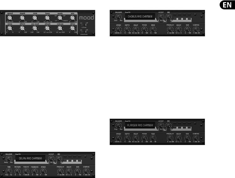
Mood Filter |
Chorus + Chamber |
The Mood Filter uses an LFO generator and an auto-envelope generator to control a VCF (voltage-controlled filter), as well as a side chain function where the channel B signal controls the envelope of channel A. When applied to electronic instruments, the Mood Filter can be used to emulate the natural sound of acoustic instruments. (Inspired by the MiniMoog)
This filter can be modulated with the signal’s envelope using the ENV MOD (with positive and negative amounts), ATTACK and RELEASE knobs, or the LFO can modulate the filter. The WAVE knob selects between 7 different wave forms
– triangular, sine, saw plus, saw minus, ramp, square, and random. The PHASE can be offset by up to 180 degrees. The SPEED knob adjusts the rate of the LFO and the DEPTH adjusts the amount of LFO modulation. Adjust the resonance of the filter until self-oscillation with the RESO(nance) knob. BASE adjusts the range of the filter from 20 Hz to 15 kHz. The MODE switch selects between low pass
(LP), high-pass (HP), band-pass (BP) and Notch. Use the MIX knob to blend the effected signal with the dry sound. With the 4 POLE switch engaged, there will be a steeper slope than the OFF (2 pole) setting. The DRIVE knob adjusts the level and can also introduce an overdrive effect (as with real analogue filters) if pushed hard. In Sidechain mode, only the left input signal is processed and fed to both outputs. The envelope of the right input signal can be used as a modulation source.
Delay + Chamber
Here we have combined Delay and Chamber reverb, so a single device can provide a variety of delay settings, plus add just the right type and amount of reverb to the selected signal. This device only uses one FX slot. (The Reverb is Inspired by the Lexicon PCM 70)
Use the BALANCE knob to adjust the ratio between delay and reverb.
Low frequencies can be excluded with the LO CUT knob, and the MIX adjusts how much of the effect is added to the signal. The TIME knob adjusts the delay time for the left channel delay, and the PATTERN sets the delay ratio for the right channel delay. Adjust the FEEDBACK and trim some high frequencies with the FEED HC (high-cut) knob. The XFEED knob allows you to send the delay sound to the reverb effect, so instead of running completely parallel, the reverb effects the echos to a selected degree. The PREDELAY knob determines the hesitation before the reverb affects the signal. The DECAY knob adjusts how quickly the reverb fades. The SIZE controls how large or small the simulated space is (room, cathedral, etc.). The DAMPING knob determines the decay of high frequencies within the reverb tail.
Taking up only one FX slot, the Chorus + Chamber effect combines the shimmer and doubling characteristics of a studio-grade Chorus with the sweet sound of a traditional Chamber reverb. (Reverb is Inspired by the Lexicon PCM 70)
The BALANCE knob adjusts the balance between chorus and reverb. Low frequencies can be excluded with the LO CUT knob, and the MIX knob adjusts how much of the effect is added to the signal. SPEED, DELAY and DEPTH adjust the rate, delay, and modulation depth of the chorus. The LFO PHASE between left and right channel can be offset by up to 180 degrees, and WAVE adjusts the LFO waveform from a sine wave to triangular wave. The PREDELAY knob determines the hesitation before the reverb affects the signal. The DECAY knob adjusts how quickly the reverb fades. The SIZE controls how large or small the simulated space is (room, cathedral, etc.). The DAMPING knob determines the decay of high frequencies within the reverb tail.
Flanger + Chamber
Add the mind-bending, filter-sweeping effect of a state-of-the-art Flanger to the elegant sweetening of a traditional Chamber reverb—all in one FX slot. (Reverb is Inspired by the Lexicon PCM 70)
The BALANCE knob adjusts the ratio between flanger and reverb. Low frequencies can be excluded with the LO CUT knob, and the MIX knob adjusts how much of the effect is added to the signal. SPEED, DELAY and DEPTH adjust the rate, delay, and modulation depth of the flanger. FEEDback can be adjusted with positive and negative amounts. The PHASE can be offset by up to 180 degrees. The PREDELAY knob determines the hesitation before the reverb affects the signal. The DECAY knob adjusts how quickly the reverb fades. The SIZE controls how large or small the simulated space is (room, cathedral, etc.). The DAMPING knob determines the decay of high frequencies within the reverb tail.
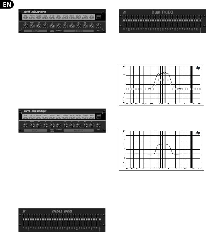
18 X32 RACK DIGITAL MIXER User Manual
Delay + Chorus |
Dual / Stereo TruEQ |
This combination effect merges a user-definable Delay (echo) with a studioquality Chorus sure to fatten up even the “skinniest” track. Uses only one FX slot. (Inspired by the TC Electronic D-Two)
The TIME knob adjusts the delay time, and the PATTERN knob sets the delay ratio for the right channel and negative values activate a cross feedback between the two channels. The FEEDHC knob adjusts the delay high-cut frequency,
while the FEEDBACK knob adjusts the number of repeats. The X-FEED knob allows you to send the delay sound to the chorus effect. The BALANCE knob adjusts
the ratio between delay and chorus. SPEED, DELAY and DEPTH adjust the rate, delay, and modulation depth of the chorus. The right channel LFO PHASE can be offset by up to 180 degrees, and WAVE adjusts the chorus character by shaping the LFO waveform from sine wave to triangular wave. Use the MIX knob to blend the effected signal with the “dry” sound.
Delay + Flanger
This handy dynamic duo blends the “woosh” of soaring jet planes with classic Delay, and can be adjusted from mild to wild. This combination effect only takes up one FX slot. (Inspired by the TC Electronic D-Two)
The TIME knob adjusts the delay time, and the PATTERN knob sets the delay ratio for the right channel and negative values activate a cross feedback between the two channels. The FEEDHC knob adjusts the delay high-cut frequency,
while the FEEDBACK knob adjusts the number of repeats. The X-FEED knob allows you to send the delay sound to the flanger effect. The BALANCE knob adjusts the ratio between delay and flanger. SPEED, DELAY and DEPTH adjust the rate, delay, and modulation depth of the flanger. The right channel LFO PHASE can be offset by up to 180 degrees, and FEED (positive and negative amounts) adjusts the feedback effect. Use the MIX knob to blend the effected signal with the “dry” sound.
Dual / Stereo GEQ
These are standard graphic equalizers that provide 31 bands of adjustment between 20 Hz and 20 kHz. A master volume slider compensates for changes in volume caused by the equalization. A maximum boost or cut of 15 dB is available for each band.
The TruEQ incorporates a special algorithm that compensates for the gain adjustment overlapping effect that adjacent frequency bands have on one another. On a standard EQ, when neighboring bands are boosted together, the resulting effect is magnified beyond what is visible from the positioning of the sliders.
Graphic equalizer without frequency response correction.
This compensated EQ will produce an adjustment that is identical to the actual positioning of the sliders.
Graphic equalizer with frequency response correction.
Dual / Stereo DeEsser
Rotate the 1st and 2nd encoder to adjust the low and high-band reduction respectively. Press the 1st encoder to select male or female to optimize the frequency for the vocalists range. Repeat the steps for the B channel using the 3rd and 4th encoders. If using the Stereo DeEsser, press the 5th encoder to select between Stereo or Mono/Stereo, which allows the left and right channels to be adjusted independently.

19X32 RACK DIGITAL MIXER User Manual
5.Topic Guide
5.1 Starting up, shutting down, and firmware updates
We recommend switching the X32 RACK on before any active sound reinforcement system is connected. The function called “Safe Main Levels”, located in the Setup/General Preferences screen, automatically turns down the main LRC bus levels when booting the console, and also prevents any scene loading actions from affecting (specifically turning up) the main levels.
Synchronization and Sample Rate settings can also be adjusted on the Setup/Config page, but please note that changing the sample rate will require a console reboot.
◊Please Note: Settings under ‘Link Preferences’, ‘Panning Mode’,
and ‘DCA groups’ are stored with the Scene data while all other settings made on the Setup/Config page are not stored in any preset and will not be initialized either. Please verify before using the X32 RACK that the sample rate is set correctly and if the synchronization source is selected appropriately. If set to external synchronization via one of the two AES50 ports, while no clock source is actually connected or switched on, then the corresponding small square icon in the main display’s top row would be red rather than green. In normal state you should only see 1-4 green squares in the top section depending on the units connected.
Note that if the X32 RACK has previously been in use by somebody else, and you feel unsure about its actual status, you can reset it to default settings in either of two convenient ways:
1.While the console is booting up and the “X32” logo appears on the screen, press and hold the “Scenes / UNDO” button, keeping it depressed until the console is fully operational and the Home screen is displayed. The console will now be in the exact same state as it was when first shipped from the factory. However, you can immediately revert back to the status the console was in before being switched off by pressing the Scenes/UNDO button.
2.You can also reset the console any time after booting by pressing “Setup/Config” -> “Initialize”.
The X32 RACK regularly stores the console’s status to its onboard flash memory, so there is usually nothing wrong with switching it off, and you do not have to explicitly save the current status. However, when a large number of parameters have been recently changed, storing all of them to flash can take up to 1 minute, in a “worst-case” scenario. In order to prevent any errors by losing power during this type of storage operation, we recommend using the “Safe Shutdown” function from the Setup/Global page, an operation similar to un-mounting a USB thumb-drive from your PC.
Updates:
The X32 RACK firmware can easily be updated by performing the following steps:
• Download the new console firmware from the X32 RACK product page onto the root level of a USB thumb drive
• Plug the USB thumb drive into the front panel USB connector while the console is turned off
• Hold the USB button depressed while switching the console on. While booting, the X32 will run a fully automatic firmware update, which will take 2-3 minutes longer than the regular boot sequence
When no update file is available on the USB drive, or when it is corrupted, the update mode will remain active, preventing the X32 RACK from booting
regularly. Switch the console off and back on without holding the USB button to boot the console with the existing firmware.
The USB socket is not suitable for other non-memory USB devices like keyboards, mice, lamps, etc.
5.2 Default setup for connecting to monitoring and P.A. systems
The X32 RACK comes pre-configured with the local XLR inputs connected to input channels 1-16, and XLR outputs 1-6 connected to the mix bus masters 1-6. The Main LR (stereo) signal is normally put out on XLR outputs 7 and 8.
The Monitoring outputs on ¼" connectors, and the Phones output always carries either the Monitor Source signal or any solo signal, whenever a solo button is active. Press the View button in the Monitor section to check or change the solo and monitoring preferences.
1.Power up the X32 RACK console first, before any connected power amps or speakers are switched on.
2.Connect cables to XLR outputs 7 and 8 on the rear panel, connecting the other ends of the cables to the inputs of your P.A. system. These normally carry the main stereo bus left and right.
3.All buses or input channels that are to be put out on the main PA system must have their Main LR Bus switches on. Use the selected channel’s pan control to place the signal within the main stereo field, and the channel’s fader to set the volume.
4.Use the rear panel Monitoring outputs to connect monitor speakers or, if you prefer, use the ¼" output in the front panel to connect your headphones. You will either hear the monitor source signal, which is Main Stereo by default, or any channel with its solo button being active.
5.3 How do I connect a microphone, process its signal and send it out to the P.A. system?
1.Turn the Channel Select knob to select the desired channel and press the knob to confirm. Make sure the Channel Level knob is turned down.
2.On the Home screen, “home” tab, press the Layer down button and ensure that the phantom power is disengaged.
3.Connect a microphone to XLR input 1 on the X32 RACK’s rear panel.
4.Engage the phantom power for channel 1 if the microphone requires it (such as a condenser mic).
Note - It is best practice to mute the respective channels prior to switching their phantom power supply on or off. Otherwise, the change of charge may cause an audible popping noise. Gain adjustments might also produce audible click noise when adjust shortly after having switched phantom power on or off.
5.On the “home” tab’s first layer, adjust the Gain knob (1st encoder) to set the gain as necessary, using the input meter on the left side of the screen as
a guide.
6.Also on the “home” tab, adjust the channel's Gate and Compressor as desired.
7.Press the Page Select right button to access the EQ tab and adjust the channel's equalization if necessary.
8.Press the 6th encoder to assign the channel to the main bus, then adjust the encoder to place the signal within the stereo field.
9.Adjust the Channel Level knob for channel 1 to the 0 dB region, then slowly turn up the Main LR Level knob until you hear the mic signal amplified through your P.A. system.

20X32 RACK DIGITAL MIXER User Manual
5.4How do I add one of the 8 internal effects to the sound?
There are two types of effects that are commonly used:
• “Effects Loop” (side chain) style effects, where multiple channels all send varying amounts of their signal to a common effect, such as a reverb, delay, or chorus.
• “Insert” style effects that are inserted in to the signal path of a single channel of audio. Examples would be a graphic EQ, filter, exciter,
or tube emulator.
To apply an “Effects Loop” style effect:
• Press the “Effects” menu button. The main screen will show the FX home screen where different effects processors are assigned to the 8 processing slots.
• Adjust rotary encoder #6 to highlight the first effects processor; it will be surrounded by an orange outline.
• Adjust rotary encoder #1 and rotary encoder #2, selecting your desired bus as the source for both the left and right inputs of the first effect processor.
• Adjust rotary encoder #5 to select a specific effect processor, such as “Ambience”.
• Rotate the Channel Select knob until 1 L appears in the channel number display and press the knob. Use the Channel Level knob to bring the return up to 0 dB. Turn the Channel Select knob to the right one click so that 1r appears in the display, the press the knob. Bring the return level up to 0 dB.
• Back on the Effects page, press the PAGE SELECT right button to switch the screen to the editor for the Ambience processor. The screen will switch to an editor page for the first processor. Adjust the rotary encoders to tailor the effect to your liking.
• Press the Home button again and tab over to the ‘sends’ page. Raise the virtual faders for the channels to which you want to add the effect.
The higher you raise the fader, the more of that channel's signal will be sent to the processor.
To apply an “insert” style effect:
• Press the “Effects” menu button.
• As the effects on the left side are also able to handle complex send effects like reverb, the slots on the right side shall be used for insert effects like limiter, graphic EQ, etc. You can also use insert effects on the left side,
but this will limit your use of reverbs and other processor-intensive effects.
• Adjust rotary encoder #6 to highlight one of the effects processors on the right side; it will be surrounded by an orange outline.
• Adjust rotary encoder #1 and rotary encoder #2, selecting “Insert” as the source for both the left and right inputs of the effect processor.
• Adjust rotary encoder #5 to select a specific effect processor, such as “precision limiter”.
• Select the specific input or output channel you wish to use the inserted effect on.
• Press the HOME button, then the PAGE SELECT right button to navigate to the selected channel’s “Config” screen.
• Adjust rotary control #6 to select the specific processor you have applied the effect to, in this case “Ins FX 5L”. Press the encoder to connect the selected insert effect.
• The Precision Limiter is now applied as an insert on the selected channel. Sending more than one channel through the same insert effect is, of course, prohibited. There will be a warning when you try to insert an effect slot that has already been used as an insert on any other channel. Both sides of a dual type effect can be used as inserts on different channels or buses.
5.5 How do I use an outboard effects processor?
In some situations, you may wish to use a loop-style effect provided by an external effect processor, as opposed to using one of the eight built-in processors. To do so:
• Press the ROUTE button, page right to the “Aux Out” screen, and adjust the first and fourth encoders to tie a rear panel ¼" aux out, such as Aux Out 1, to an available mix bus, such as Mix Bus 2.
• Patch rear panel Aux Output 1 to the input of your external effects processor.
• Patch the output of the external effects processor to rear panel Aux Input 1.
• Rotate the Channel Select knob until A1 appears in the display, the press the knob. On the Home screen, ‘home’ tab, verify that the Main LR is highlighted.
• Move the Aux 1 channel level to 0 dB.
• Adjust the settings on the external effects processor to taste.
5.6 How do I set up live stage monitoring?
Setting up a live stage monitor mix using conventional monitors:
1.Press the ROUTE button and page right to the Analog Out page.
2.Adjust the first encoder to select a rear panel analog output (e.g. Output 1), then adjust the fourth encoder to select a mix bus (e.g. Mix Bus 1). When the source and destination have been selected, press the 4th encoder to complete the assignment.
3.Adjust the 5th encoder to set up the monitor send as pre-fader, or pre/post EQ. This will prevent the monitor mix from changing when the front-of- house mix is adjusted.
4.Connect a cable from rear panel analog Out 1 to the input of:
a)A powered stage monitor
b)An external amplifier feeding a passive stage monitor
c)A transmitter for a set of wireless in-ear monitors
5.Rotate the Channel Select knob to select Bus 1, then press the knob. Adjust the Channel Level knob to 0 dB. You can change the output on this bus later.
6.To adjust the mix sent to the monitor, select an input channel with the Channel Select knob, nagivate to the Home screen’s ‘sends’ tab, then raise the faders for each bus that the channel should be sent to.
Loading...