


Quick Start Guide (Check out behringer.com for Full Manual)
X32 COMPACT DIGITAL MIXER
Compact 40-Input, 25-Bus Digital Mixing Console with
16 Programmable MIDAS Preamps, 17 Motorized Faders, Channel LCDs,
32-Channel Audio Interface and iPad/iPhone Remote Control
2 X32 COMPACT DIGITAL MIXER
Important Safety
Instructions
Terminals marked with this symbol carry electrical current of sufficient magnitude to constitute risk of electric shock.
Use only high-quality professional speaker cables with ¼" TS or twist-locking plugs pre-installed. All other installation or modification should be performed only by qualified personnel.
This symbol, wherever it appears,
alerts you to the presence of uninsulated dangerous voltage inside the
enclosure - voltage that may be sufficient to constitute a risk of shock.
This symbol, wherever it appears, alerts you to important operating and maintenance instructions in the
accompanying literature. Please read the manual.
Caution
To reduce the risk of electric shock, do not remove the top cover (or the rear section).
No user serviceable parts inside. Refer servicing to qualified personnel.
Caution
To reduce the risk of fire or electric shock, do not expose this appliance to rain and moisture. The apparatus shall not be exposed to dripping
or splashing liquids and no objects filled with liquids, such as vases, shall be placed on the apparatus.
Caution
These service instructions are for use by qualified service personnel only.
To reduce the risk of electric shock do not perform any servicing other than that contained in the operation instructions. Repairs have to be performed by qualified service personnel.
1.Read these instructions.
2.Keep these instructions.
3.Heed all warnings.
4.Follow all instructions.
5.Do not use this apparatus near water.
6.Clean only with dry cloth.
7.Do not block any ventilation openings. Install in accordance with the manufacturer’s instructions.
8.Do not install near any heat sources such as radiators, heat registers, stoves, or other apparatus (including amplifiers) that produce heat.
9.Do not defeat the safety purpose of the polarized or grounding-type plug. A polarized plug has two blades with one wider than the other. A grounding-type plug has two blades and a third grounding prong. The wide
blade or the third prong are provided for your safety. If the provided plug does not fit into your outlet, consult an electrician for replacement of the obsolete outlet.
10.Protect the power cord from being walked on or pinched particularly at plugs, convenience receptacles, and the point where they exit from the apparatus.
11.Use only attachments/accessories specified by
the manufacturer.
12. Use only with the cart, stand, tripod, bracket,
or table specified by the
manufacturer, or sold with the apparatus. When a cart is used, use caution when
moving the cart/apparatus combination to avoid
injury from tip-over.
13.Unplug this apparatus during lightning storms or when unused for long periods of time.
14.Refer all servicing to qualified service personnel. Servicing is required when the apparatus has been damaged in any way, such as power supply cord or plug is damaged, liquid has been spilled or objects have fallen into the apparatus, the apparatus has been exposed
to rain or moisture, does not operate normally, or has been dropped.
15.The apparatus shall be connected to a MAINS socket outlet with a protective earthing connection.
16.Where the MAINS plug or an appliance coupler is used as the disconnect device, the disconnect device shall remain readily operable.
LEGAL DISCLAIMER
TECHNICAL SPECIFICATIONS AND APPEARANCES ARE SUBJECT TO CHANGE WITHOUT NOTICE AND ACCURACY IS NOT GUARANTEED. BEHRINGER, KLARK TEKNIK, MIDAS, BUGERA, AND TURBOSOUND
ARE PART OF THE MUSIC GROUP (MUSIC-GROUP.COM). ALL TRADEMARKS ARE THE PROPERTY OF THEIR RESPECTIVE OWNERS. MUSIC GROUP ACCEPTS NO LIABILITY FOR ANY LOSS WHICH MAY BE SUFFERED BY ANY PERSON WHO RELIES EITHER WHOLLY OR
IN PART UPON ANY DESCRIPTION, PHOTOGRAPH OR STATEMENT CONTAINED HEREIN. COLORS AND
SPECIFICATIONS MAY VARY FROM ACTUAL PRODUCT. MUSIC GROUP PRODUCTS ARE SOLD THROUGH AUTHORIZED FULLFILLERS AND RESELLERS ONLY. FULLFILLERS AND RESELLERS ARE NOT AGENTS OF MUSIC GROUP AND HAVE ABSOLUTELY NO AUTHORITY
TO BIND MUSIC GROUP BY ANY EXPRESS OR IMPLIED
UNDERTAKING OR REPRESENTATION. THIS MANUAL IS COPYRIGHTED. NO PART OF THIS MANUAL MAY BE REPRODUCED OR TRANSMITTED IN ANY FORM OR BY ANY MEANS, ELECTRONIC OR MECHANICAL,
INCLUDING PHOTOCOPYING AND RECORDING OF ANY KIND, FOR ANY PURPOSE, WITHOUT THE EXPRESS WRITTEN PERMISSION OF MUSIC GROUP IP LTD.
ALL RIGHTS RESERVED.
© 2013 MUSIC Group IP Ltd.
Trident Chambers, Wickhams Cay, P.O. Box 146, Road Town, Tortola, British Virgin Islands
LIMITED WARRANTY
For the applicable warranty terms and conditions and additional information regarding MUSIC Group’s
Limited Warranty, please see complete details online at www.music-group.com/warranty.
Instrucciones de seguridad
Las terminales marcadas con este símbolo transportan corriente eléctrica de magnitud suficiente como para constituir
un riesgo de descarga eléctrica. Utilice solo cables de altavoz profesionales y de alta calidad con conectores TS de 6,3 mm o de bayoneta prefijados. Cualquier otra
instalación o modificación debe ser realizada únicamente por un técnico cualificado.
Este símbolo, siempre que aparece, le advierte de la presencia de voltaje peligroso sin aislar dentro de la caja;
este voltaje puede ser suficiente para constituir un riesgo de descarga.
Este símbolo, siempre que aparece,
le advierte sobre instrucciones operativas y de mantenimiento que aparecen en la
documentación adjunta. Por favor, lea el manual.
Atención
Para reducir el riesgo de descarga eléctrica, no quite la tapa (o la parte
posterior). No hay piezas en el interior del equipo que puedan ser reparadas por el usuario. Si es necesario, póngase en contacto con personal cualificado.
Atención
Para reducir el riesgo de incendio o descarga eléctrica, no exponga este
aparato a la lluvia, humedad o alguna otra fuente que pueda salpicar o derramar algún líquido sobre el aparato. No coloque ningún tipo de recipiente para líquidos sobre el aparato.
Atención
Las instrucciones de servicio deben llevarlas a cabo exclusivamente personal
cualificado. Para evitar el riesgo de una descarga eléctrica, no realice reparaciones que no se encuentren descritas en el manual de operaciones. Las reparaciones deben ser realizadas exclusivamente por personal cualificado.
1.Lea las instrucciones.
2.Conserve estas instrucciones.
3.Preste atención a todas las advertencias.
4.Siga todas las instrucciones.
5.No use este aparato cerca del agua.
6.Limpie este aparato con un paño seco.
7.No bloquee las aberturas de ventilación. Instale el equipo de acuerdo con las instrucciones del fabricante.
8.No instale este equipo cerca de fuentes de calor tales como radiadores, acumuladores de calor, estufas u otros aparatos (incluyendo amplificadores) que puedan producir calor.
9.No elimine o deshabilite nunca la conexión a tierra del aparato o del cable de alimentación de corriente. Un enchufe polarizado tiene dos polos, uno de los cuales tiene un contacto más ancho que el otro. Una clavija con puesta a tierra dispone de tres contactos: dos polos y la puesta a tierra. El contacto ancho y el tercer contacto, respectivamente, son los que garantizan una mayor seguridad. Si el enchufe suministrado con el equipo no concuerda con la toma de corriente, consulte con un electricista para cambiar la toma de corriente obsoleta.
10.Coloque el cable de suministro de energía de manera que no pueda ser pisado y que esté protegido de objetos afilados. Asegúrese de que el cable de suministro de energía esté protegido, especialmente en la zona de la clavija y en el punto donde sale del aparato.
11.Use únicamente los dispositivos o accesorios especificados por el fabricante.
12.Use únicamente la
carretilla, plataforma, trípode, soporte o mesa
especificados por el fabricante o suministrados junto con el equipo.
Al transportar el equipo, tenga cuidado para evitar
daños y caídas al tropezar con algún obstáculo.
13.Desenchufe el equipo durante tormentas o si no va a utilizarlo durante un periodo largo.
14.Confíe las reparaciones únicamente a servicios técnicos cualificados. La unidad requiere mantenimiento siempre que haya sufrido algún daño, si el cable de suministro de energía o el enchufe presentaran daños,
se hubiera derramado un líquido o hubieran caído objetos dentro del equipo, si el aparato hubiera estado expuesto a la humedad o la lluvia, si ha dejado de funcionar de manera normal o si ha sufrido algún golpe o caída.
15.Al conectar la unidad a la toma de corriente eléctrica asegúrese de que la conexión disponga de una unión
a tierra.
16.Si el enchufe o conector de red sirve como único medio de desconexión, éste debe ser accesible fácilmente.
Quick Start Guide |
3 |
NEGACIÓN LEGAL
LAS ESPECIFICACIONES TÉCNICAS Y LA APARIENCIA EXTERIOR ESTÁN SUJETAS A CAMBIOS SIN
PREVIO AVISO Y NO PODEMOS GARANTIZAR LA TOTAL EXACTITUD DE TODO LO QUE APARECE AQUÍ. BEHRINGER, KLARK TEKNIK, MIDAS, BUGERA, Y TURBOSOUND SON PARTE DEL GRUPO MUSIC GROUP (MUSIC-GROUP.COM). TODAS LAS MARCAS REGISTRADAS SON PROPIEDAD DE SUS RESPECTIVOS DUEÑOS. MUSIC GROUP NO ACEPTA NINGÚN TIPO DE RESPONSABILIDAD POR POSIBLES DAÑOS Y PERJUICIOS SUFRIDOS POR CUALQUIER PERSONA QUE SE HAYA BASADO COMPLETAMENTE O EN PARTE EN LAS DESCRIPCIONES, FOTOGRAFÍAS O EXPLICACIONES QUE APARECEN EN ESTE DOCUMENTO. LOS COLORES Y ESPECIFICACIONES TÉCNICAS PUEDEN VARIAR LIGERAMENTE DE UN
PRODUCTO A OTRO. LOS PRODUCTOS MUSIC GROUP SON COMERCIALIZADOS ÚNICAMENTE A TRAVÉS DE DISTRIBUIDORES OFICIALES. LOS DISTRIBUIDORES Y MAYORISTAS NO SON AGENTES DE MUSIC GROUP, POR LO QUE NO ESTÁN AUTORIZADOS A CONCEDER NINGÚN TIPO DE CONTRATO O GARANTÍA QUE OBLIGUE A MUSIC GROUP DE FORMA EXPRESA O IMPLÍCITA. ESTE MANUAL ESTÁ PROTEGIDO POR LAS LEYES DEL COPYRIGHT. ESTE MANUAL NO PUEDE SER REPRODUCIDO O TRANSMITIDO, NI COMPLETO NI EN PARTE, POR NINGÚN TIPO DE MEDIO, TANTO SI ES ELECTRÓNICO COMO MECÁNICO, INCLUYENDO EL
FOTOCOPIADO O REGISTRO DE CUALQUIER TIPO Y PARA CUALQUIER FIN, SIN LA AUTORIZACIÓN EXPRESA Y POR ESCRITO DE MUSIC GROUP IP LTD.
RESERVADOS TODOS LOS DERECHOS. © 2013 MUSIC Group IP Ltd.
Trident Chambers, Wickhams Cay, P.O. Box 146, Road Town, Tortola, British Virgin Islands
GARANTÍA LIMITADA
Si quiere conocer los detalles y condiciones aplicables de la garantía así como información adicional sobre la
Garantía limitada de MUSIC group, consulte online toda la información en la web www.music-group.com/warranty.
4 X32 COMPACT DIGITAL MIXER
Consignes de sécurité
Les points repérés par ce symbole portent une tension électrique suffisante pour constituer un risque d’électrocution.
Utilisez uniquement des câbles d’enceintes professionnels de haute qualité avec fiches Jack mono 6,35 mm ou fiches à verrouillages déjà installées. Toute autre installation ou modification doit être effectuée uniquement par un personnel qualifié.
Ce symbole avertit de la présence d’une tension dangereuse et non isolée à l’intérieur de l’appareil - elle peut
provoquer des chocs électriques.
Attention
Ce symbol signale les consignes d’utilisation et d’entre ! Tien importantes
dans la documentation fournie. Lisez les consignes de sécurité du manuel d’utilisation de l’appareil.
Attention
Pour éviter tout risque de choc électrique, ne pas ouvrir le capot de l’appareil ni
démonter le panneau arrière. L’intérieur de l’appareil ne possède aucun élément réparable par l’utilisateur. Laisser toute réparation à un professionnel qualifié.
Attention
Pour réduire les risques de feu et de choc électrique, n’exposez pas cet appareil à la pluie, à la moisissure, aux gouttes ou aux éclaboussures.
Ne posez pas de récipient contenant un liquide sur l’appareil (un vase par exemple).
Attention
Ces consignes de sécurité et d’entretien sont destinées à un personnel qualifié.
Pour éviter tout risque de choc électrique, n’effectuez aucune réparation sur l’appareil qui ne soit décrite par le manuel d’utilisation. Les éventuelles réparations doivent être effectuées uniquement par un technicien spécialisé.
1.Lisez ces consignes.
2.Conservez ces consignes.
3.Respectez tous les avertissements.
4.Respectez toutes les consignes d’utilisation.
5.N’utilisez jamais l’appareil à proximité d’un liquide.
6.Nettoyez l’appareil avec un chiffon sec.
7.Veillez à ne pas empêcher la bonne ventilation
de l’appareil via ses ouïes de ventilation. Respectez les consignes du fabricant concernant l’installation
de l’appareil.
8.Ne placez pas l’appareil à proximité d’une source de chaleur telle qu’un chauffage, une cuisinière ou tout appareil dégageant de la chaleur (y compris un ampli de puissance).
9.Ne supprimez jamais la sécurité des prises bipolaires ou des prises terre. Les prises bipolaires possèdent deux contacts de largeur différente. Le plus large est le contact de sécurité. Les prises terre possèdent deux contacts plus une mise à la terre servant de sécurité. Si la prise du bloc d’alimentation ou du cordon d’ali-mentation fourni ne correspond pas à celles de votre installation électrique, faites appel à un électricien pour effectuer le changement de prise.
10.Installez le cordon d’alimentation de telle façon que personne ne puisse marcher dessus et qu’il soit protégé d’arêtes coupantes. Assurez-vous que le cordon d’alimentation est suffisamment protégé, notamment au niveau de sa prise électrique et de l’endroit où il est relié à l’appareil; cela est également valable pour une éventuelle rallonge électrique.
11.Utilisez exclusivement des accessoires et des appareils supplémentaires recommandés par le fabricant.
12.Utilisez exclusivement des
chariots, des diables,
des présentoirs, des pieds et des surfaces de
travail recommandés par le fabricant ou
livrés avec le produit. Déplacez précautionneusement tout chariot ou diable chargé pour éviter d’éventuelles blessures en cas de chute.
13.Débranchez l’appareil de la tension secteur en cas d’orage ou si l’appareil reste inutilisé pendant une longue période de temps.
14.Les travaux d’entretien de l’appareil doivent
être effectués uniquement par du personnel qualifié. Aucun entretien n’est nécessaire sauf si l’appareil est endommagé de quelque façon que ce soit (dommages sur le cordon d’alimentation ou la prise par exemple), si un liquide ou un objet a pénétré à l’intérieur du châssis, si l’appareil a été exposé à la pluie ou à l’humidité, s’il ne fonctionne pas correctement ou à la suite d’une chute.
15. L’appareil doit être connecté à une prise secteur dotée d’une protection par mise à la terre.
16. La prise électrique ou la prise IEC de tout appareil dénué de bouton marche/arrêt doit rester accessible en permanence.
DÉNI LÉGAL
CARACTÉRISTIQUES TECHNIQUES ET APPARENCE SUJETTES À MODIFICATIONS SANS PRÉAVIS. PRÉCISION NON GARANTIE. BEHRINGER, KLARK TEKNIK, MIDAS, BUGERA, ET TURBOSOUND FONT PARTIE DU MUSIC GROUP (MUSIC-GROUP.COM). TOUTES LES MARQUES DÉPOSÉES SONT LA PROPRIÉTÉ DE LEURS PROPRIÉTAIRES RESPECTIFS. LA SOCIÉTÉ MUSIC GROUP N’ACCEPTE AUCUNE RESPONSABILITÉ DANS LES ÉVENTUELS DOMMAGES OU PERTES SUBIS PAR UN TIERS EN SE BASANT EN ENTIER OU EN PARTIE SUR LES DESCRIPTIONS, PHOTOGRAPHIES OU DÉCLARATIONS CONTENUES DANS CE DOCUMENT. LES COULEURS ET CARACTÉRISTIQUES PEUVENT VARIER LÉGÈREMENT DE CELLES DU PRODUIT.
LES PRODUITS MUSIC GROUP NE SONT VENDUS QUE PAR LE BIAIS DE REVENDEURS AGRÉÉS.
LES DISTRIBUTEURS ET LES REVENDEURS NE SONT PAS AGENTS DE MUSIC GROUP ET N’ONT ABSOLUMENT AUCUNE AUTORITÉ POUR ENGAGER OU REPRÉSENTER LA SOCIÉTÉ MUSIC GROUP DE FAÇON IMPLICITE, EXPLICITE OU INDIRECTE. CE MODE D’EMPLOI EST PROTÉGÉ PAR DROITS D’AUTEURS. IL EST INTERDIT
DE TRANSMETTRE OU DE COPIER CE MODE D’EMPLOI SOUS QUELLE FORME QUE CE SOIT, PAR QUEL MOYEN QUE CE SOIT, ÉLECTRONIQUE OU MÉCANIQUE,
CE QUI COMPREND LES MOYENS DE PHOTOCOPIE ET D’ENREGISTREMENT DE QUELLE FAÇON QUE CE SOIT, QUEL QUE SOIT LE BUT, SANS LA PERMISSION ÉCRITE EXPRESSE DE MUSIC GROUP IP LTD.
TOUS DROITS RÉSERVÉS.
© 2013 MUSIC Group IP Ltd.
Trident Chambers, Wickhams Cay, P.O. Box 146, Road Town, Tortola, Iles Vierges Britanniques
GARANTIE LIMITÉE
Pour connaître les termes et conditions de garantie applicables, ainsi que les informations supplémentaires et détaillées sur la Garantie Limitée de MUSIC Group, consultez le site Internet www.music-group.com/warranty.
Wichtige
Sicherhteitshinweise
Vorsicht
Die mit dem Symbol markierten Anschlüsse führen so viel Spannung,
dass die Gefahr eines Stromschlags besteht. Verwenden Sie nur hochwertige, professionelle Lautsprecherkabel mit vorinstallierten 6,35 mm MONO-Klinkensteckern oder Lautsprecherstecker mit Drehverriegelung. Alle anderen Installationen oder Modifikationen sollten nur von qualifiziertem Fachpersonal ausgeführt werden.
Achtung
Um eine Gefährdung durch Stromschlag auszuschließen, darf die Geräteabdeckung
bzw. Geräterückwand nicht abgenommen werden.
Im Innern des Geräts befinden sich keine vom Benutzer reparierbaren Teile. Reparaturarbeiten dürfen nur von qualifiziertem Personal ausgeführt werden.
Achtung
Um eine Gefährdung durch Feuer bzw. Stromschlag auszuschließen, darf dieses
Gerät weder Regen oder Feuchtigkeit ausgesetzt werden noch sollten Spritzwasser oder tropfende Flüssigkeiten in das Gerät gelangen können. Stellen Sie keine mit Flüssigkeit gefüllten Gegenstände, wie z. B. Vasen,
auf das Gerät.
Achtung
Die Service-Hinweise sind nur durch qualifiziertes Personal zu befolgen.
Um eine Gefährdung durch Stromschlag zu vermeiden, führen Sie bitte keinerlei Reparaturen an dem Gerät durch, die nicht in der Bedienungsanleitung beschrieben sind. Reparaturen sind nur von qualifiziertem Fachpersonal durchzuführen.
1.Lesen Sie diese Hinweise.
2.Bewahren Sie diese Hinweise auf.
3.Beachten Sie alle Warnhinweise.
4.Befolgen Sie alle Bedienungshinweise.
5.Betreiben Sie das Gerät nicht in der Nähe von Wasser.
6.Reinigen Sie das Gerät mit einem trockenen Tuch.
7.Blockieren Sie nicht die Belüftungsschlitze. Beachten Sie beim Einbau des Gerätes die Herstellerhinweise.
8.Stellen Sie das Gerät nicht in der Nähe von Wärmequellen auf. Solche Wärmequellen sind z. B. Heizkörper, Herde oder andere Wärme erzeugende Geräte (auch Verstärker).
9.Entfernen Sie in keinem Fall die Sicherheitsvorrichtung von Zweipoloder geerdeten Steckern. Ein Zweipolstecker hat zwei unterschiedlich breite Steckkontakte. Ein geerdeter Stecker hat zwei Steckkontakte und einen dritten Erdungskontakt. Der breitere Steckkontakt oder der zusätzliche
Erdungskontakt dient Ihrer Sicherheit. Falls das mitgelieferte Steckerformat nicht zu Ihrer Steckdose passt, wenden Sie sich bitte an einen Elektriker, damit die Steckdose entsprechend ausgetauscht wird.
10.Verlegen Sie das Netzkabel so, dass es vor Tritten und scharfen Kanten geschützt ist und nicht
beschädigt werden kann. Achten Sie bitte insbesondere im Bereich der Stecker, Verlängerungskabel und an
der Stelle, an der das Netzkabel das Gerät verlässt, auf ausreichenden Schutz.
11.Das Gerät muss jederzeit mit intaktem Schutzleiter an das Stromnetz angeschlossen sein.
12.Sollte der Hauptnetzstecker oder eine Gerätesteckdose die Funktionseinheit zum Abschalten sein, muss diese immer zugänglich sein.
13.Verwenden Sie nur Zusatzgeräte/Zubehörteile, die laut Hersteller geeignet sind.
14.Verwenden
Sie nur Wagen,
Standvorrichtungen,
Stative, Halter oder Tische, die vom Hersteller benannt oder im Lieferumfang
des Geräts enthalten sind. Falls Sie einen
Wagen benutzen, seien Sie vorsichtig beim Bewegen der Wagen-Gerätkombination, um Verletzungen durch Stolpern zu vermeiden.
15.Ziehen Sie den Netzstecker bei Gewitter oder wenn Sie das Gerät längere Zeit nicht benutzen.
16.Lassen Sie alle Wartungsarbeiten nur von qualifiziertem Service-Personal ausführen. Eine Wartung ist notwendig, wenn das Gerät in irgendeiner Weise beschädigt wurde (z. B. Beschädigung des Netzkabels oder Steckers), Gegenstände oder Flüssigkeit in das Geräteinnere gelangt sind, das Gerät Regen oder Feuchtigkeit ausgesetzt wurde, das Gerät nicht ordnungsgemäß funktioniert oder auf den Boden gefallen ist.
17. Korrekte Entsorgung dieses Produkts: Dieses Symbol weist darauf hin, das Produkt entsprechend der WEEE Direktive (2002/96/EC) und der jeweiligen nationalen Gesetze nicht zusammen mit Ihren
Haushaltsabfällen zu entsorgen. Dieses Produkt sollte bei einer autorisierten Sammelstelle für Recycling elektrischer und elektronischer Geräte (EEE) abgegeben werden. Wegen bedenklicher Substanzen, die generell mit elektrischen und elektronischen Geräten in Verbindung stehen, könnte eine unsachgemäße Behandlung dieser Abfallart eine negative Auswirkung auf Umwelt und Gesundheit haben. Gleichzeitig gewährleistet Ihr Beitrag zur richtigen Entsorgung dieses Produkts die effektive Nutzung natürlicher Ressourcen. Für weitere Informationen zur Entsorgung Ihrer Geräte bei einer Recycling-Stelle nehmen Sie bitte Kontakt zum zuständigen städtischen Büro, Entsorgungsamt oder zu Ihrem Haushaltsabfallentsorger auf.
Quick Start Guide |
5 |
HAFTUNGSAUSSCHLUSS
TECHNISCHE DATEN UND ERSCHEINUNGSBILD KÖNNEN UNANGEKÜNDIGT GEÄNDERT WERDEN. IRRTÜMER BLEIBEN VORBEHALTEN. BEHRINGER, KLARK TEKNIK, MIDAS, BUGERA UND TURBOSOUND SIND TEIL DER MUSIC GROUP (MUSIC-GROUP.COM). ALLE WARENZEICHEN SIND DAS EIGENTUM IHRER JEWEILIGEN BESITZER. MUSIC GROUP ÜBERNIMMT KEINE HAFTUNG FÜR VERLUSTE, DIE PERSONEN ENTSTEHEN, DIE SICH GANZ ODER TEILWEISE AUF HIER ENTHALTENE BESCHREIBUNGEN, FOTOS ODER AUSSAGEN VERLASSEN. ABGEBILDETE FARBEN UND SPEZIFIKATIONEN KÖNNEN GERINGFÜGIG VOM PRODUKT ABWEICHEN. MUSIC GROUP PRODUKTE WERDEN NUR ÜBER AUTORISIERTE FACHHÄNDLER VERKAUFT. DIE VERTRIEBSPARTNER UND HÄNDLER SIND KEINE VERTRETER VON MUSIC GROUP UND SIND NICHT BERECHTIGT, MUSIC GROUP DURCH AUSDRÜCKLICHE ODER STILLSCHWEIGENDE HANDLUNGEN ODER REPRÄSENTANZEN ZU VERPFLICHTEN. DIESE BEDIENUNGSANLEITUNG IST URHEBERRECHTLICH GESCHÜTZT. KEIN TEIL DIESES HANDBUCHS DARF IN IRGENDEINER FORM ODER MIT IRGENDWELCHEN MITTELN ELEKTRONISCH ODER MECHANISCH, INKLUSIVE FOTOKOPIE ODER AUFNAHME, ZU IRGENDEINEM ZWECK OHNE
DIE SCHRIFTLICHE ZUSTIMMUNG DER FIRMA MUSIC GROUP IP LTD. VERVIELFÄLTIGT ODER ÜBERTRAGEN WERDEN.
ALLE RECHTE VORBEHALTEN.
© 2013 MUSIC Group IP Ltd.
Trident Chambers, Wickhams Cay, P.O. Box 146, Road Town, Tortola, British Virgin Islands
BESCHRÄNKTE GARANTIE
Die geltenden Garantiebedingungen und zusätzliche Informationen bezüglich der von MUSIC Group gewährten beschränkten Garantie finden Sie online unter www. music-group.com/warranty.
6 X32 COMPACT DIGITAL MIXER
Instruções de Segurança
Importantes
Aviso!
Terminais marcados com o símbolo carregam corrente elétrica de magnitude
suficiente para constituir um risco de choque elétrico. Use apenas cabos de alto-falantes de alta qualidade com plugues TS de ¼" ou plugues com trava de torção
pré-instalados. Todas as outras instalações e modificações devem ser efetuadas por pessoas qualificadas.
Este símbolo, onde quer que o encontre, alerta-o para a leitura das instruções de manuseamento que acompanham o
equipamento. Por favor leia o manual de instruções.
Atenção
De forma a diminuir o risco de choque eléctrico, não remover a cobertura
(ou a secção de trás). Não existem peças substituíveis por parte do utilizador no seu interior. Para esse efeito recorrer a um técnico qualificado.
Atenção
Para reduzir o risco de incêndios ou choques eléctricos o aparelho não deve ser
exposto à chuva nem à humidade. Além disso, não deve ser sujeito a salpicos, nem devem ser colocados em cima do aparelho objectos contendo líquidos, tais como jarras.
Atenção
Estas instruções de operação devem ser utilizadas, em exclusivo, por técnicos de
assistência qualificados. Para evitar choques eléctricos não proceda a reparações ou intervenções, que não as indicadas nas instruções de operação, salvo se possuir as qualifi-cações necessárias. Para evitar choques eléctricos não proceda a reparações ou intervenções, que não as indicadas nas instruções de operação. Só o deverá fazer se possuir as qualificações necessárias.
1.Leia estas instruções.
2.Guarde estas instruções.
3.Preste atenção a todos os avisos.
4.Siga todas as instruções.
5.Não utilize este dispositivo perto de água.
6.Limpe apenas com um pano seco.
7.Não obstrua as entradas de ventilação. Instale de acordo com as instruções do fabricante.
8.Não instale perto de quaisquer fontes de calor tais como radiadores, bocas de ar quente, fogões de sala ou outros aparelhos (incluindo amplificadores) que produzam calor.
9.Não anule o objectivo de segurança das fichas polarizadas ou do tipo de ligação à terra. Uma ficha polarizada dispõe de duas palhetas sendo uma mais larga do que a outra. Uma ficha do tipo ligação à terra dispõe
de duas palhetas e um terceiro dente de ligação à terra.
A palheta larga ou o terceiro dente são fornecidos para sua segurança. Se a ficha fornecida não encaixar na sua tomada, consulte um electricista para a substituição da tomada obsoleta.
10.Proteja o cabo de alimentação de pisadelas ou apertos, especialmente nas fichas, extensões, e no local de saída da unidade. Certifique-se de que o cabo eléctrico está protegido. Verifique particularmente nas fichas, nos receptáculos e no ponto em que o cabo sai do aparelho.
11.O aparelho tem de estar sempre conectado à rede eléctrica com o condutor de protecção intacto.
12.Se utilizar uma ficha de rede principal ou uma tomada de aparelhos para desligar a unidade de funcionamento, esta deve estar sempre acessível.
13.Utilize apenas ligações/acessórios especificados pelo fabricante.
14.Utilize apenas com o carrinho, estrutura,
tripé, suporte, ou mesa
especificados pelo fabricante ou vendidos com o dispositivo.
Quando utilizar um carrinho, tenha cuidado ao
mover o conjunto carrinho/dispositivo para evitar danos provocados pela terpidação.
15.Desligue este dispositivo durante as trovoadas ou quando não for utilizado durante longos períodos de tempo.
16.Qualquer tipo de reparação deve ser sempre efectuado por pessoal qualificado. É necessária uma reparação sempre que a unidade tiver sido de alguma forma danificada, como por exemplo: no caso do cabo de alimentação ou ficha se encontrarem danificados; na eventualidade de líquido ter sido derramado ou objectos terem caído para dentro do dispositivo; no caso da unidade ter estado exposta à chuva ou à humidade; se esta não funcionar normalmente, ou se tiver caído.
17.Correcta eliminação deste produto: este símbolo indica que o produto não deve ser eliminado juntamente com os resíduos
domésticos, segundo a Directiva REEE (2002/96/CE) e a legislação nacional. Este produto deverá
ser levado para um centro de recolha licenciado para a reciclagem de resíduos de equipamentos eléctricos e electrónicos (EEE). O tratamento incorrecto deste tipo de resíduos pode ter um eventual impacto negativo no ambiente e na saúde humana devido a substâncias potencialmente perigosas que estão geralmente
associadas aos EEE. Ao mesmo tempo, a sua colaboração para a eliminação correcta deste produto irá contribuir para a utilização eficiente dos recursos naturais. Para mais informação acerca dos locais onde poderá deixar o seu equipamento usado para reciclagem, é favor contactar os serviços municipais locais, a entidade de gestão de resíduos ou os serviços de recolha de resíduos domésticos.
LEGAL RENUNCIANTE
ESPECIFICAÇÕES TÉCNICAS E APARÊNCIA ESTÃO SUJEITAS A MUDANÇAS SEM AVISO PRÉVIO E NÃO HÁ GARANTIA DE PRECISÃO . BEHRINGER, KLARK TEKNIK, MIDAS, BUGERA, E TURBOSOUND FAZEM PARTE
DO MUSIC GROUP (MUSIC-GROUP.COM). TODAS AS MARCAS REGISTADAS SÃO PROPRIEDADE DOS SEUS RESPECTIVOS PROPRIETÁRIOS. MUSIC GROUP NÃO SE RESPONSABILIZA POR QUALQUER PERDA QUE POSSA TER SIDO SOFRIDA POR QUALQUER PESSOA QUE ACREDITA TANTO COMPLETA QUANTO PARCIALMENTE EM QUALQUER DESCRIÇÃO, FOTO OU AFIRMAÇÃO AQUI CONTIDA. CORES E ESPECIFICAÇÕES PODEM VARIAR UM POUCO DO PRODUTO. OS PRODUTOS
DA MUSIC GROUP SÃO VENDIDOS ATRAVÉS DE DISTRIBUIDORES AUTORIZADOS APENAS. DISTRIBUIDORES E REVENDEDORES NÃO SÃO
AGENTES DA MUSIC GROUP E NÃO TÊM AUTORIDADE ALGUMA PARA OBRIGAR A MUSIC GROUP A QUALQUER TAREFA OU REPRESENTAÇÃO EXPRESSA OU IMPLÍCITA. ESTE MANUAL TEM DIREITOS AUTORAIS. PARTE ALGUMA DESTE MANUAL PODE SER REPRODUZIDA OU TRANSMITIDA DE QUALQUER FORMA OU MEIO, ELETRÔNICO OU MECÂNICO, INCLUINDO FOTOCÓPIA E GRAVAÇÃO DE QUALQUER TIPO, PARA QUALQUER INTENÇÃO, SEM A PERMISSÃO ESCRITA EXPRESSA DE MUSIC GROUP IP LTD.
TODOS DIREITOS RESERVADOS.
© 2013 MUSIC Group IP Ltd.
Trident Chambers, Wickhams Cay, P.O. Box 146, Road Town, Tortola, Ilhas Virgens Britânicas
GARANTIA LIMITADA
Para obter os termos de garantia aplicáveis e condições e informações adicionais a respeito da garantia limitada do MUSIC group, favor verificar detalhes na íntegra através do website www.music-group.com/warranty.
Quick Start Guide |
7 |
8 X32 COMPACT DIGITAL MIXER
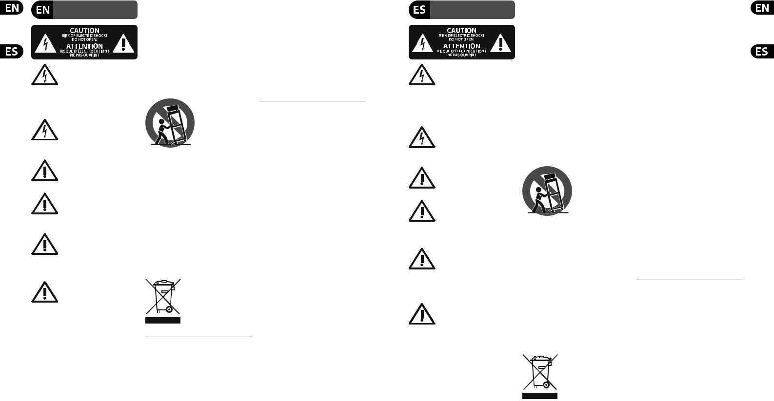
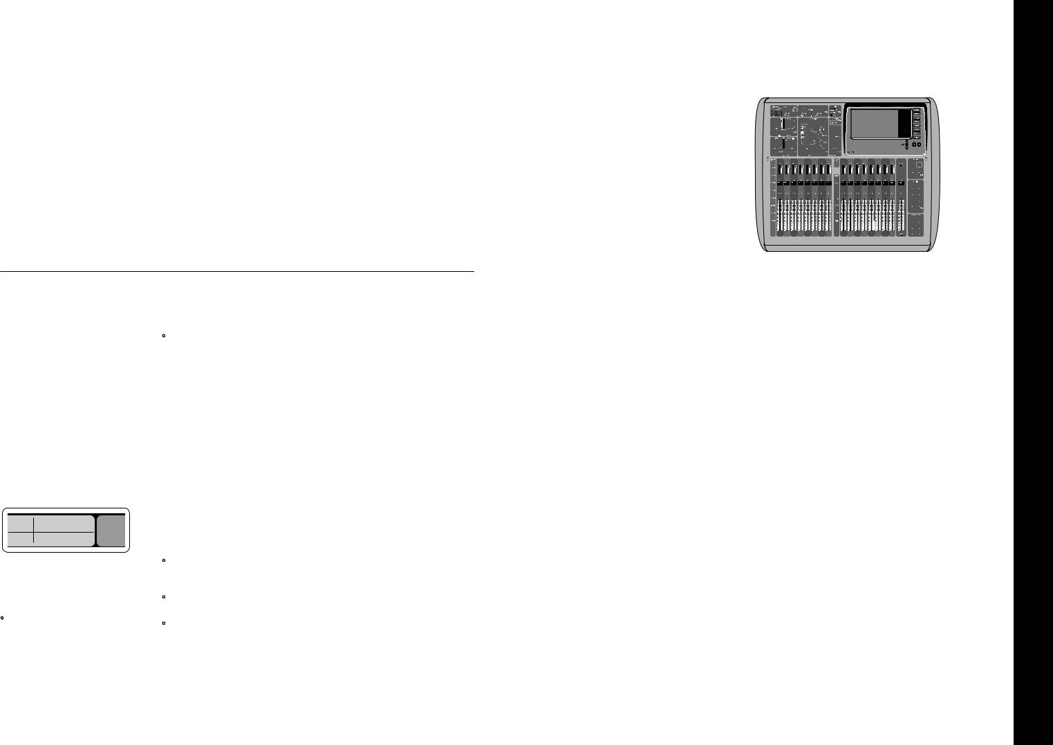
X32 COMPACT DIGITAL MIXER Getting Started
(EN) |
Getting Started |
(1) |
(3) |
(2) |
(4) |
(5) |
Mixer Operational Overview
Welcome to the X32 COMPACT digital mixing console Quick Start Guide! This document will give you an overview of the basic operations of the mixer, allowing you to get up and running quickly. While reading through the information in this
document, we encourage you to experiment with the console’s different screens and controls. The console’s user interface was designed to be extremely easy
to navigate through and learn. In addition to this Quick Start Guide, there is an English user manual available as a PDF download from behringer.com.
General user interface operation
The X32 COMPACT user interface is divided into five major sections:
(1)Channel Strip and Monitoring
(2)Input Channels
(3)Display
(4)Group/Bus/Main Channels
(5)Scenes/Assign/Mute Groups
View buttons rule
Throughout the top panel of the console,
you will find small buttons labeled View. Press these buttons to immediately switch the console’s large color display (known as the Main Display) to show information related to the section whose View button you have just pressed.
For example, if you are editing the equalizer and feel like seeing a large display of the EQ frequency response curve or corresponding EQ parameter value, simply press the adjacent View
button in the EQ section. If you need to check where the monitor signal is being routed, simply press the View button next to the Phones Level knob and the main display will show the details.
With the View button approach of the X32 COMPACT console, there is almost never a need to drill down through multiple menu pages, since the View buttons will always take you directly to the relevant screen.
Tip: The Setup/Global tab on the main display allows preferences for the behavior of View and Select buttons to be adjusted.
Customizing the X32 COMPACT through the Utilities page
Press the Utility button, located to the right of the main display, to bring up useful functions in a “context-sensitive” manner. For example:
•When you are adjusting the equalizer of a console channel, pressing the Utility button will offer copying, pasting, loading or saving of equalizer settings
•Pressing the Utility button while holding a channel select button depressed will present a naming screen where you can customize the
channel’s appearance on both the main display as well as the small channel display
•On the Routing pages, pressing the Utility button will offer loading or saving different presets of routing scenarios
•In the Scenes menu, pressing the Utility button offers copying, loading, saving or naming console scenes
Sometimes there is more to say
Some of the individual pages on the main display contain
more adjustable parameters
than can be controlled by
the 6 rotary push encoders located beneath it. In these cases there is a small page
number indication, e.g. “1/2”. Simply press the Layer Up/Down buttons to switch between layers.
9 Quick Start Guide
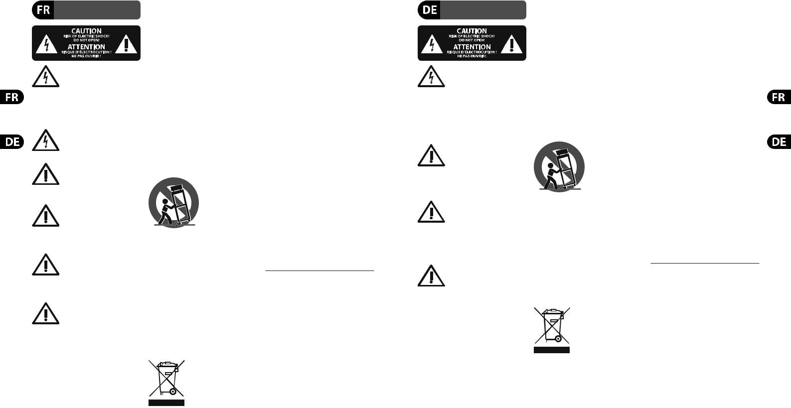
Section 1: Channel Strip and Monitoring
The X32 COMPACT’s channel strip offers dedicated controls for the most important processing parameters of the currently selected channel.
To adjust controls for a given channel strip, simply press the Select button on the desired input or output channel.
Certain sections of the channel strip (such as the low cut filter, noise gate, EQ and compressor) contain a respectively labeled button that can be pressed to switch the specific effect on and off. The button illuminates to show the effect is active, and goes dark when bypassed.
Within the channel strip, the rotary control knobs are surrounded by an amber LED collar that indicates the parameter’s value. Whenever this backlit knob is turned off, it indicates that this specific control/parameter is not available for the selected channel type. For example, if an output bus is currently selected, the LED collar and the gain knob are turned off, because there is no input gain to be controlled on an output bus.
The channel strip consists of the following sub-sections:
•Config/Preamp
•Gate, Dynamics
•Equalizer
•Main Bus
Each of these subsections correspond to the processing steps of the currently selected channel, and they each have their own View button
that, when pressed, switches the Main Display to a page displaying all related parameters for that subsection.
Monitoring and Talkback
There are two separate Level controls in this section, one for the headphone outputs located on either side of the console, and a second one for the monitor outputs located on the rear panel.
Press the section’s View button to edit various monitoring preferences, such as the input source for the phones bus and the monitor outputs.
This section also contains independent Talkback buttons (A and B). Press the View button next to the Phones Level knob, then press Page Select right to access the Talkback A and B edit pages. These screens also contain settings for the optional goose-neck lamp and the console’s internal test-tone generator.
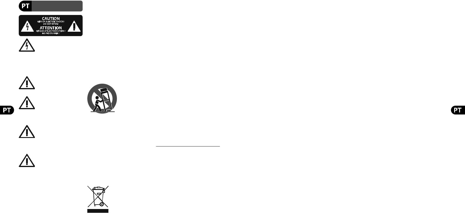
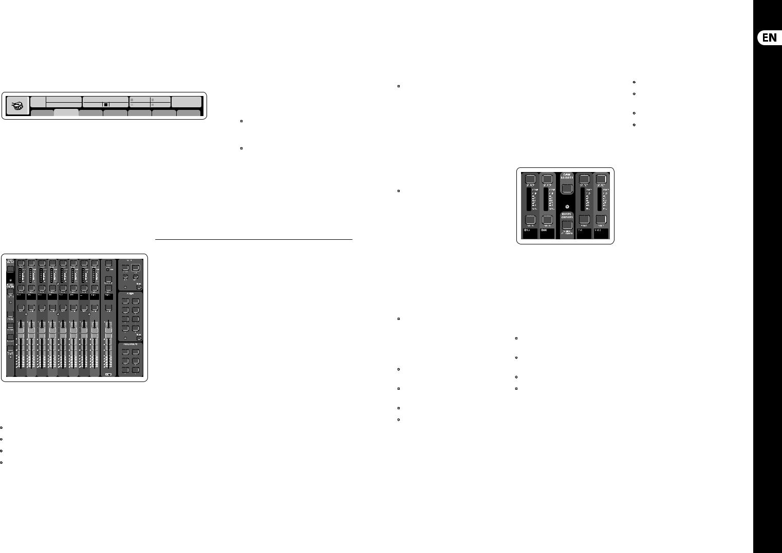
Section 2: Input Channel Banks
You will find a select button on top of every channel that is used to direct the control focus of the user interface, including all channel related parameters
(channel strip and main display), to that channel. Please note that at any time, there is exactly one channel selected (either Input Ch 1-32,
Aux 1-6/USB, FX Returns 1L-4R, Mix Bus 1-16, Main LR/C, or Matrix 1-6). DCA Groups
(digitally controlled amplifier) cannot be selected because they control a number of assigned channels rather than one specific channel.
The Input Channels section of the console is located on the left hand side, and offers 8 separate input channel strips. These 8 channel strips represent six separate layers of inputs for the console, including:
•Input Channels 1-8
•Input Channels 9-16
•Input Channels 17-24
•Input Channels 25-32
•Aux Inputs 1-6/USB playback
•Effects Returns
Press any of the correspondingly labeled layer buttons on the left side of the console to switch the input channel bank to any of the six layers listed above. The button will illuminate, reminding you which layer is active.
Two more layers (Bus Master 1-8 and 9-16) are also offered, allowing you to adjust the
levels of the 16 Mix Bus Masters, which is useful when you wish to include Bus Masters into DCA Group assignments.
On each fader strip you will find a motorized 100 mm level fader, Mute and Solo buttons, a Gate indicator, an input level meter, Compressor indicator, and the channel select button.
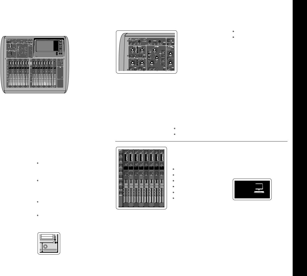
Each of the 8 input channels has an individual
(and customizable) color LCD screen that can display a channel number, nickname, and even a graphical channel icon. In the event that a channel’s input source has been changed to an input signal that differs from the default setup, the LCD display will also indicate the name of the actual input source.
Ch01 PC
Aux5
Soundcard
Example: Channel 01 has the nickname Soundcard and is fed from Aux input 5.
10 X32 COMPACT DIGITAL MIXER
X32 COMPACT DIGITAL MIXER Getting Started
(EN) Getting Started
Ch01 |
01 02: next |
0:00 |
- 0:00 |
B: - |
C: X-USB |
15:33: 15 |
|
OpeningScene |
|
|
A: S16 |
A: 48K |
|
||
FatSnare |
home |
con g |
gate |
dyn |
eq |
sends |
main |
Section 3: Main Display Area
The main color display presents information about various sections of the console. It can be switched to different screens using the console’s View buttons, as well as any of the 8 buttons on the right side of the display.
The top section of the main display permanently covers useful status information. The top left corner shows the selected channel number, its nickname and the selected icon. The next block shows the current scene number and name in amber, as well
as the next upcoming scene. The center section displays the playback file name along with elapsed and remaining time and a recorder status icon. The next block to the right has 4 segments to show the status of AES50 ports A and B, the Card slot and the audio clock synchronization source and sample rate (top right). Small green square indicators show
proper connectivity. The right most block shows the console time that can be set under Setup/Config.
When working with any given screen, press the Page keys located on the display bezel to switch to different screen pages.
Editing parameters or settings on each of the screens is done using the 6 associated push-encoders along the bottom edge of the display.
•Whenever there is a continuous control or list entry, you can turn the corresponding knob for editing, which is indicated by various circular icons
•When there is a switch or toggle function on one of these knobs, you will see a broad
rectangular button along the lower edge of the field. Pressing the encoder changes the on/off state of the corresponding function. When the rectangular button in the display is dark grey,
the corresponding function is off/inactive; when it is amber, the function is on/active
Section 4: Group/Bus Channel Banks
This section of the console offers eight channel strips, divided into the following layers:
•Eight DCA (digitally controlled amplifier) groups
•Mix Bus masters 1-8
•Mix Bus masters 9-16
•Matrix Outputs 1-6, and the main center bus
This section also contains a main LR output fader, which is independent and always available no matter which channel bank or layer is active.
When using the DCA Groups layer, the DCA Groups can be soloed and muted, but they cannot be selected. To edit the DCA group names, icons and colors, navigate to the Setup/DCA Groups page on the main display. DCA group names, icons and color can also be edited by pressing the Utility and
Select button concurrently. Once the Setup/scribble strip page is open you can directly select any other channel for editing its layout in the same run.
When using any of the output bus layers, note that the bottom LEDs on the meters in this section illuminate when the respective bus is fed from pre-fader sources of the selected channel.
11 Quick Start Guide
Section 5: Various Assignments (DCA groups, mute groups, custom assignable controls)
• Assigning DCA Groups
Thanks to the two distinct fader groups (inputs on the left, outputs on the right), the task of assigning channels or buses to a virtual DCA Group is a breeze on the X32 COMPACT. Simply hold the respective DCA Group Select button on the right-hand side of the console, while pressing the Select buttons for all the input channels that you wish to assign to said DCA Group. You can also press the DCA Group Select button in order to check which channels are already assigned to it. The assigned channel Select buttons will light up.
• Assigning Mute Groups
The mute group assignment process is similar to the above, but is designed with an additional precaution in order to prevent accidental muting of channels during a show. To assign input/ output channels to one of the six mute groups (controlled by the buttons located to the right of the Main LR fader) you need to first switch on the Mute Grp button next to the main display. While holding the desired Mute Group button, select the desired input and output channels, which will now be assigned to the Mute Group. When you are done with assignment, switch off Mute Grp at the display, and the 6 Mute Group buttons will work as intended.
• Custom Assignable Controls:
The Assign section of the console offers three banks of 8 buttons, allowing for freely customizable access to 24 random functions on the X32 Compact.
To make a custom assignment:
•Press the View button in the Assign section to edit the assignments
•Select the set of controls you wish to edit (A, B or C)
•Select the control 1-8 you wish to assign
•Select the parameter you wish to control and assign the function
Usually this is used to control a specific channel’s parameter, like the lead vocalist’s reverb
on/off status.
The Jump-to-Page control is a special target type that does not alter any audio parameter, but rather brings you directly to any specified display page.
The “Sends on Faders” Function
The X32 console features a very useful function that can be accessed by pressing the dedicated Sends on Faders button, located between the two fader sections.
The Sends on Faders function aids with level setting of channels sent to any of the 16 Mix Buses. It is only for channels assigned to Mix Buses 1-16, and does NOT work for DCA groups, main or matrix buses. The Sends on Faders function works in
two convenient ways to cover the most obvious situations in a live sound environment :
When preparing a monitor mix for a specific musician
•Select the monitor bus (1-8, 9-16) that feeds the talent’s stage monitor
•Press the Sends on Faders button; it will illuminate
•Select one of the six input channel layers
•As long as the Sends on Faders is active, all faders in the input channels section (located on the left side of the console) correspond to the send levels to the selected (monitor) mix bus
When checking/editing where a selected input signal is (to be) sent to
•Select the input channel in the left section
•Press the Sends on Faders button; it will illuminate
•Select either bus channel layer 1-8 or 9-16
•The bus faders (located on right side of the console) now represent the send levels from the selected input channel (located on the left side of the console)
The option to use Sends on Faders in both ways, selecting an input or an output channel, is a special feature of the X32.

12 X32 COMPACT DIGITAL MIXER
X32 COMPACT DIGITAL MIXER Getting Started
(EN) Getting Started
Ch01 |
01 |
01: |
0:00 |
- 0:00 |
B: - |
C: X-USB |
13:45 : 19 |
|
|
|
|
A: S16 |
A: 48K |
|
|
home analog out |
aux out p16 out card out |
aes50-a aes50-b |
|||||
|
|
Channel Processing Block Patch |
|
|
Connected Devices |
||
Inputs 1-8 |
|
Inputs 9-16 |
Inputs 17-24 |
Inputs 25-32 |
Aux In 1-4 |
AES50 A |
|
Local In 1-8 |
|
Local In 1-8 |
Local In 1-8 |
Local In 1-8 |
Aux 1-4 |
|
|
Local In 9-16 |
|
Local In 9-16 |
Local In 9-16 |
Local In 9-16 |
Local 1-4 |
|
|
[Local In 17-24] |
[Local In 17-24] |
[Local In 17-24] |
[Local In 17-24] |
AES50 A1-4 |
|
||
[Local In 25-32] |
[Local In 25-32] |
[Local In 25-32] |
[Local In 25-32] |
AES50 B1-4 |
|
||
AES50 A1-8 |
|
AES50 A1-8 |
AES50 A1-8 |
AES50 A1-8 |
Card 1-4 |
|
|
AES50 A9-16 |
|
AES50 A9-16 |
AES50 A9-16 |
AES50 A9-16 |
|
|
|
AES50 A17-24 |
|
AES50 A17-24 |
AES50 A17-24 |
AES50 A17-24 |
|
|
AES50 B |
AES50 A25-32 |
|
AES50 A25-32 |
AES50 A25-32 |
AES50 A25-32 |
|
|
|
AES50 A33-40 |
|
AES50 A33-40 |
AES50 A33-40 |
AES50 A33-40 |
|
|
|
AES50 A41-48 |
|
AES50 A41-48 |
AES50 A41-48 |
AES50 A41-48 |
|
|
|
AES50 B1-8 |
|
AES50 B1-8 |
AES50 B1-8 |
AES50 B1-8 |
|
|
|
AES50 B9-16 |
|
AES50 B9-16 |
AES50 B9-16 |
AES50 B9-16 |
|
|
|
AES50 B17-24 |
|
AES50 B17-24 |
AES50 B17-24 |
AES50 B17-24 |
|
|
|
AES50 A25-32 |
|
AES50 A25-32 |
AES50 A25-32 |
AES50 A25-32 |
|
|
|
Local inputs 17-24 and 25-32 are listed with brackets, indicating that these are not physically available on this device. Assigning these will obviously carry no signal, but they can still be used when preparing shows for a full X32 console.
Cabling for all AES50 connections between X32 and S16 stageboxes:
•Shielded CAT-5e cable, Ethercon terminated cable ends
•Maximum cable length 100 meters (330 feet)
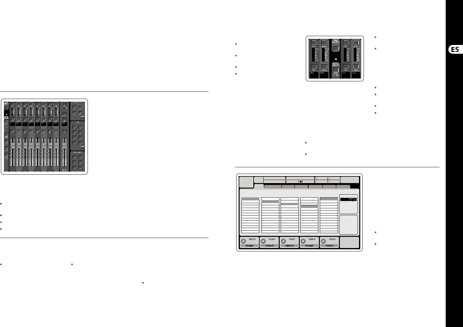
Routing I/O
The X32 COMPACT console features 16 analog rear-panel XLR inputs with microphone preamps, as well as
8 rear-panel XLR Outputs and 6 TRS Aux Sends and Returns. In addition, there are two AES50 ports,
each featuring 48 input and output channels, and a card slot for 32 channels of input and output to and from a connected computer via USB 2.0.
Input Signals can be attached to the console’s internal audio processing engine in blocks of 8 signals from any one of the aforementioned input sources.
Note: All signal blocks patched to the audio processing will be connected to the corresponding input channels automatically.
Ch01 |
01 |
01: |
0:00 |
- 0:00 |
|
B: - |
|
C: X-USB 14:09 |
: 37 |
|||||||
|
|
|
|
|
|
|
|
|
|
|
A: S16 |
|
A: 48K |
|
||
|
|
analog out |
|
|
|
|
|
|
|
|
|
|
|
|
|
|
|
home |
aux out |
p16 out card out |
aes50-a aes50-b |
|
|||||||||||
|
Edit Output Assignment |
|
|
|
|
|
|
|
|
|
|
|
||||
Analog Output |
Current Setting |
|
Category |
|
|
|
Processed Output |
Signal Tap |
|
|||||||
Output 01 |
MixBus |
OFF |
OFF |
Pre EQ |
0.3 |
ft |
Output 02 |
|
Main (LRC) |
Main L |
Post EQ |
0.10 |
m |
Output 03 |
|
Mix Bus |
Main R |
Pre Fader |
||
|
0.3 |
ms |
||||
Output 04 |
|
Matrix |
Main C/M |
Post Fader |
||
Output 05 |
|
Direct Out |
Main Bus 01 |
|
|
|
Output 06 |
|
Monitor |
Main Bus 02 |
|
|
|
Output 07 |
|
|
Main Bus 03 |
|
Delay |
|
Output 08 |
|
|
Main Bus 04 |
|
|
|
|
|
|
|
|
||
*Output 09 |
|
|
Main Bus 05 |
|
|
|
*Output 10 |
|
|
Main Bus 06 |
|
|
|
*Output 11 |
|
|
Main Bus 07 |
|
|
|
*Output 12 |
|
|
Main Bus 08 |
|
Delay |
|
*Output 13 |
|
|
Main Bus 09 |
|
|
|
|
|
|
|
|
||
*Output 14 |
|
|
|
|
|
|
Select |
Select |
Select |
Select |
Delay |
0.3 ms
Assign |
Set |
Delay |
Output Signals can be freely assigned from
any internal signal to any of the following outputs:
•8 analog local XLR outputs (with adjustable digital delay for time-alignment of speakers)
•8 virtual outputs (marked with *) for routing over AES50 or card outputs
•6 auxiliary sends on ¼" TRS outputs + 2x AES/EBU outputs
•16 channels personal monitoring using the console’s P-16 Bus output connector
Any and all of the above signals can also be mirrored in blocks of 8 signals on either one of
•48x channels on AES50 port A
•48x channels on AES50 port B
•32x channels on USB interface card
13 Quick Start Guide
Ch01 |
01 01: |
|
0:00 |
- 0:00 |
B: - |
C: X-USB |
14:11 : 37 |
||
|
|
|
|
|
A: S16 |
A: 48K |
|
|
|
|
home |
con g |
gate |
dyn |
eq |
sends |
main |
||
|
|
|
|
|
|
Insert Position |
|
|
|
clip |
|
|
|
In |
t |
|
|
|
|
-6 |
48V |
|
|
|
|
|
|
||
-12 |
Reverse |
|
|
|
|
|
|
|
|
-18 |
|
|
|
|
|
|
|
||
|
|
|
|
Delay |
Pre |
Ins |
Post |
||
-24 |
|
|
|
|
|||||
|
|
|
|
0.3 |
ft |
|
|
|
|
-30 |
Link |
Lo Cut |
|
Source |
|
|
Insert |
||
-36 |
|
0.10 |
m |
|
|
||||
|
OFF |
|
OFF |
||||||
-42 |
+0.0 dB |
2.0 |
Hz |
Input 01 |
0.03 |
ms |
|
InsFX 1L |
|
-48 |
|
|
|
Input 02 |
|
|
|
InsFX 1R |
|
-54 |
|
|
|
Input 03 |
|
|
|
InsFX 2L |
|
|
Gain |
Lo Cut |
|
Input 04 |
Delay |
|
|
InsFX 2R |
|
|
|
Input 05 |
|
|
InsFX 3L |
||||
|
|
|
|
Input 06 |
|
|
|
InsFX 3L |
|
Gain |
|
Lo Cut |
|
Source |
Delay |
Ins Pos |
|
Insert |
|
+0.00 dB |
20 |
Hz |
Input |
0.3 ms |
PRE |
|
InsF |
||
Link |
|
Lo Cut |
|
Select |
Delay |
|
Insert |
|
Connect |
Input Channels 1-16 are pre-configured to use the local input signals 1-16, but can be patched to use any other available signal on the audio engine as well, including mix bus/sub group outputs. Changes of the Channel Source can be made on the Preamp Config page.
Input Channels 17-32 are pre-configured to AES50 A inputs 1-16, so that connecting an
S16 stage box to port A will automatically feed the channels.
Aux Return Channels 1-8 are pre-configured to use the 6 aux input signals, and the two USB playback outputs, but can be patched to use any other available signal of the console as well.
FX Return Channels 1L-4R control the 4 stereo output signals of side-chain FX 1-4.
LeOnde.mp3 |
|
|
13:44:43 |
|
|
|
|
|
MyProj.prj |
|
|
|
|
|
|
|
|
|
|
|
|
00.05.00 |
00.00.00 |
|
29 November 2010 |
|
|
|
Scene01 |
|||
home |
con g |
|
gate |
dyn |
eq |
sends |
main |
|||
|
|
clip |
Bus Con guration |
|
Bus Insert Position |
||||||||
|
|
|
Channel Sends |
∑ |
|
|
|
|
|
|
|
||
|
|
-6 |
|
|
|
|
|
|
|
|
|||
|
|
-12 |
|
|
|
|
|
|
|
|
|
|
|
|
|
-18 |
|
|
|
|
|
|
|
|
|
|
|
|
|
Link |
Pre |
Insert |
Post |
||||||||
|
|
-24 |
|||||||||||
|
|
-30 |
All Channel Sends |
|
|
|
|
Insert |
|||||
|
|
-36 |
|
|
|
|
|||||||
|
|
|
|
|
|||||||||
|
|
-42 |
Pre Con guration |
|
|
|
Ins 01 |
|
|||||
|
|
-48 |
|
... |
|
|
|
|
Ins 02 |
|
|||
|
|
|
|
|
|||||||||
|
|
-54 |
|
Inputs |
|
|
|
|
Ins 03 |
|
|||
|
|
|
Pre EQ |
|
|
|
|
Ins 04 |
|
||||
|
|
|
|
|
|||||||||
|
|
|
|
Pre Fader |
|
|
|
|
... |
|
|
|
|
|
|
|
|
Post Fader |
|
|
|
|
FX 01 |
|
|||
|
|
|
|
Sub Grou |
|
|
|
|
FX 02 |
|
|||
|
|
|
|
|
|
|
|
|
|
|
|
|
|
Gain |
Send Pos. |
Insert Pos. |
Insert |
00.00 dB |
Inputs |
Pre |
|
Link |
Bus Sends |
Insert |
Connect |
The configuration of Mix Bus Channels 1-16 can be pre-set (in the Setup/Global page) or can also be configured on an individual, per-channel basis. The bus processing includes (in this order):
•Insert point (swappable between post-EQ and pre-EQ operation)
•6-band fully parametric EQ
•Compressor/expander (swappable between post-EQ and pre-EQ operation)
•Bus sends to 6 matrices
•Main LR panning
•Mono/Center level
Main Bus Channels LR/C are always available and independent from Mix Buses. The processing steps for this signal path include (in this order):
•Insert point (swappable between post-EQ and pre-EQ operation)
•6-band fully parametric EQ
•Compressor/expander (swappable between post-EQ and pre-EQ operation)
•Bus sends to 6 matrices
Matrix Channels 1-6 are fed exclusively by MAIN LRC and Mix Bus 1-16 signals. The processing steps include (in this order):
•Insert point (swappable between post-EQ and pre-EQ operation)
•6-band fully parametric EQ
•Compressor/expander (swappable between post-EQ and pre-EQ operation)
Effects Processing 1-8
The X32 COMPACT console contains eight truestereo internal effects engines.
•FX 1-4 can be configured as side chain or insert effects, while FX 5-8 can only be used in insert points of channels or buses
•The returns of side chain FX 1-4 can always be controlled using the 6th bank (layer) of the input channels - Effects Returns. Note that the return signals of FX 1-4 have separate faders for left and right
•The FX Home screen allows selection of the FX 1-4 input sources and selecting the effects type/algorithm for each of the 8 FX slots of the virtual rack
•The subsequent tabs FX 1-FX 8 of the FX screen allow editing all parameters of the chosen effects processor
14 X32 COMPACT DIGITAL MIXER
X32 COMPACT DIGITAL MIXER Getting Started
(EN) Getting Started
iPad App for X32 COMPACT
Many functions of the X32 COMPACT console can be remotely controlled by a dedicated iPad app. Details about the app’s download, setup and operation are included in a separate user manual available for download from the X32 COMPACT product page.
The app’s User Interface is optimized for the touchscreen nature of the iPad device and provides many useful remote features of the console.
Using the app, you can perform functions such as adjusting monitor mixes from the stage while
interacting with musicians, or adjusting the front-of- house mix from the audience, while hearing the mix exactly as the audience does.
Windows-based application and Linux/ OS X application for X32 COMPACT
Also offered is a separate remote editor running
on host computers that will allow for complete editing control of the X32 COMPACT via Ethernet. Details of the remote editor’s download, setup and operation are included in a separate user manual available for download from the X32 COMPACT product page. Check out behringer.com for more information.
Tip: The X32 COMPACT remote communication is OSC-based (open sound control) and we will share the protocol on our website, allowing developers to design their own control software. Stay tuned to behringer.com for details on the OSC protocol.
X-USB card
The X-USB card allows transmission of up to
32 channels to and from a connected computer. Please download the X-USB drivers and
Quick Start Guide from behringer.com before connecting the mixer to your computer.
Startup and Shutdown, and Update:
We recommend switching the X32 COMPACT mixer on first, and shutting it off last when any sound system is connected. This will prevent the possibility of any unexpected noises being transmitted during the startup/shutdown process.
The Setup screen’s general preference page contains a Safe Main Levels function. When activated,
the console automatically mutes the main LRC levels when booting the console. It also prevents any scene loading from affecting (i.e. turning up) the mains levels.
Synchronization and Sample Rate settings for the console can be adjusted on the Setup/Config page, but please note that sample rate changes will require a reboot of the console. When you see a red square indication at the top section of the main display, please verify if the synchronization settings on Setup/Config make sense (see section 3).
16  A 48K 15
 C X-USB
If the console has been used by someone else,
and you feel unsure about its specific routing status, you can reset the X32 COMPACT to default settings in two convenient ways:
•While the console is booting and the “X32” logo appears on the screen, press and hold the Scenes/Undo button until the console is fully operational and the Home screen is
displayed. The console will now be in the same
state as it was when shipped from the factory. However, you can immediately revert to the status the console was in when being switched off the last time by pressing the Scenes/Undo button
•You can also reset the console any time after booting by pressing Setup/Config, then Initialize
NOTE: Initializing the console does not automatically erase the current show data or any stored scenes. If you wish to clear all scenes, please use the ‘Initialize All Show Data’ option on Setup/Config page.
In order to prevent any errors by losing power during a store operation, we recommend using the “Safe Shutdown” function from the Setup/Global page.
NOTE: The X32 COMPACT can be locked against unintended use by activating ‘Lock Console’ from the Setup/Global page. In this state the UI will not allow any changes to be made and the display shows “X”. Keep HOME depressed for about 5s to unlock the X32 again.
The X32 firmware can easily be updated by performing the following steps:
•Download the new console firmware from the X32 COMPACT product page onto the root level of a USB thumb drive
•Plug the USB thumb drive into the top panel USB connector while the console is turned off
•Hold the USB View button depressed while switching the console on. While booting, the X32 COMPACT will run a fully automatic
firmware update, which will take 2-3 minutes longer than the regular boot sequence
When no update file is available on the USB drive,
or when it is corrupted, the update mode will remain active, preventing the X32 from booting regularly. Switch the console off and back on without holding the USB View button to boot the console with the existing firmware.
CAUTION: Please do not block the fan opening on the bottom of the X32 COMPACT cabinet! The large slowturning fan is barely audible, but it is still working.
Specifically when mounting the X32 COMPACT in a road case, please ensure there is sufficient space underneath to allow for some airflow.
15 Quick Start Guide
(ES) Puesta en marcha
(1) |
(3) |
(2) |
(4) |
(5) |
Resumen operativo de la mesa de mezclas
¡Bienvenido al Manual de puesta en marcha de la mesa de mezclas digital X32 COMPACT! En este documento le ofrecemos un resumen de las operaciones básicas de esta mesa de mezclas para que pueda ponerse en marcha con ella rápidamente. Mientras va leyendo este
documento, le recomendamos que experimente con las distintas pantallas y controles de la consola. El interface de usuario de esta consola ha sido diseñado para ser extremadamente fácil en cuanto a navegación y aprendizaje. Además de este manual de puesta en marcha, dispone también de un manual de instrucciones en inglés disponible como fichero PDF descargable a través de nuestra página web behringer.com.
Funcionamiento general del interface de usuario
El interface de usuario del X32 COMPACT está dividido en cinco secciones principales:
(1)Banda de canal y monitorización
(2)Canales de entrada
(3)Pantalla
(4)Canales principales/grupo/bus
(5)Grupos de anulación/escenas/asignación
Funcionamiento de los botones View
En distintos puntos del panel superior de la consola encontrará unos pequeños botones marcados como View. Pulse estos botones para hacer que la gran pantalla a color de la consola (conocida como Pantalla principal) pase a mostrarle información relacionada con la sección cuyo botón View acabe de pulsar.
Por ejemplo, si está realizando una edición del ecualizador y le interesa tener una imagen mayor de la curva de respuesta de frecuencia del EQ
o del valor del parámetro EQ correspondiente, simplemente pulse el botón View adyacente a la sección EQ. Si necesita verificar dónde está siendo rutada la señal de monitorización, simplemente pulse el botón View que está cerca del mando Phones Level y los detalles del ruteo aparecerán en la pantalla principal.
Con las opciones que le ofrece este botón View, prácticamente se elimina la necesidad de ir pasando por distintas páginas de menú,
dado que los botones View siempre le llevarán a la pantalla necesaria.
Consejo: La pestaña Setup/Global de la pantalla principal le permite ajustar las preferencias de comportamiento de los botones View y Select.
16 X32 COMPACT DIGITAL MIXER
X32 COMPACT DIGITAL MIXER Puesta en marcha
(ES) Puesta en marcha
Personalización de la X32 COMPACT por medio de la página de utilidades
Pulse el botón Utility, situado a la derecha de la pantalla principal, para activar una serie de funciones de gran utilidad de una forma “sensible al contexto”. Por ejemplo:
•Cuando esté ajustando el ecualizador de un canal de la consola, el pulsar el botón Utility le ofrecerá opciones de copia, pegados, carga o almacenamiento de ajustes del ecualizador.
•El pulsar el botón Utility mientras mantiene pulsado el botón de selección de un canal hará que aparezca una pantalla de asignación de
nombres en la que podrá personalizar el aspecto con el que aparece el canal tanto en la pantalla principal como en la pequeña pantalla de canal.
•En las páginas Routing, el pulsar el botón Utility le ofrecerá la opción de cargar o almacenar distintos ajustes prefijados de escenarios de ruteo.
•En el menú Scenes, pulse el botón Utility para que aparezcan opciones de copia, carga, almacenamiento o asignación de nombres a escenas de la consola.
A veces aún hay más cosas que decir...
Algunas de las páginas
individuales de la pantalla
principal contienen más
parámetros ajustables
de los que pueden ser controlados por los
6 mandos giratorios y de pulsación que están justo debajo de ella. En estos casos podrá ver una pequeña indicación de número de página, p.e. “1/2”. Simplemente pulse entonces los botones Layer Up/Down para cambiar de una página o estrato a la otra.
Sección 1: Banda de Canal y Monitorización
La banda de canal de la X32 COMPACT’s le ofrece controles específicos para los parámetros de procesado más importantes del canal activo o seleccionado en ese momento. Para ajustar los controles de una banda de canal determinada, simplemente pulse el botón Select del canal de entrada o salida que quiera.
Determinadas secciones de la banda de canal (como el filtro de corte de graves, la puerta de ruidos, el EQ y el compresor) contienen un botón
claramente señalizado con el nombre respectivo que puede pulsar para activar o desactivar ese efecto concreto. El botón se iluminará para indicarle en qué momento está activado el efecto y se apagará cuando el efecto esté anulado o en bypass.
Dentro de la banda de canal, los mandos de control giratorios están rodeados por un anillo de pilotos LED de color ámbar que le indican el valor del parámetro. Siempre que ese anillo luminoso esté apagado, eso le indicará que ese parámetro/control concreto no está disponible para el tipo de canal
seleccionado. Por ejemplo, si ha seleccionado un bus de salida, el anillo luminoso y el mando de ganancia estarán desactivados, dado que no puede controlar ninguna ganancia de entrada en un bus de salida.
La banda de canal está formada por las subsecciones siguientes:
•Config/Preamp (configuración/previo)
•Gate, Dynamics (puerta de ruidos, dinamismo)
•Equalizer (ecualizador)
•Main Bus (bus principal)
Cada una de estas subsecciones se corresponde con los pasos de procesado del canal elegido en ese momento y cada una de ellas tiene su propio botón View que, cuando es pulsado, hace que en la pantalla principal aparezca una página en la que podrá ver todos los parámetros relacionados con esa subsección.
Monitorización y Línea Interior (Talkback)
En esta sección encontrará dos controles de nivel independientes; uno para las salidas de auriculares que están situadas a cada lado de la consola y el segundo para las salidas de monitorización del panel trasero.
Pulse el botón View de esta sección para editar diversas opciones de preferencias de monitorización, tales como la fuente de entrada para el bus de auriculares y las salidas de monitorización.
Esta sección también contiene botones Talkback o de línea interior independientes (A y B). Pulse el botón View que está al lado del mando de nivel de
auriculares y pulse después el botón de selección de página derecho para acceder a las páginas de edición Talkback A y B. Estas pantallas también contienen ajustes para el flexo opcional y para el generador de tono de pruebas interno de la consola.
17 Quick Start Guide
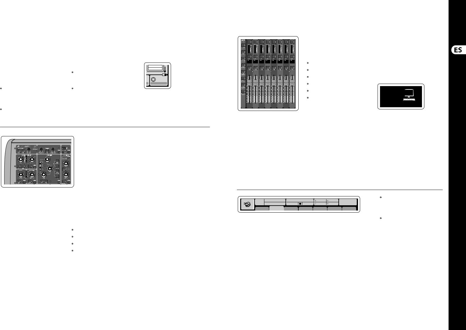
Sección 2: Bancos de Canales de Entrada
En la parte superior de cada canal encontrará un botón Select que sirve para dirigir el foco de control del interface de usuario, incluyendo todos los parámetros relacionados con el canal (banda de canal y pantalla principal) a ese canal. Tenga en cuenta que en todo momento habrá solo un canal seleccionado (sea Input Ch 1-32, Aux 1-8, FX Returns 1L-4R, Mix Bus 1-16, Main LR/C o Matrix 1-6).
Los grupos DCA (amplificador controlado digitalmente) no pueden ser seleccionados dado que controlan una serie de canales asignados en lugar de un único canal específico.
La sección de canales de entrada de la consola está situada en el lado izquierdo y le ofrece 8 bandas de canal de entrada independientes. Estas ocho bandas de canal representan seis estratos distintos de entradas de la consola, incluyendo:
•Canales de entrada 1-8
•Canales de entrada 9-16
•Canales de entrada 17-24
•Canales de entrada 25-32
•Entradas auxiliares 1-6/reproducción USB
•Retornos de efectos
Pulse cualquiera de los botones de estrato con la correspondiente etiqueta que están en el lado izquierdo de la consola para cambiar el banco de
canales de entrada a cualquiera de los seis estratos anteriores. El botón se iluminará, para indicarle que está activo el estrato elegido.
Dispone de dos estratos más (Bus máster 1-8 y 9-16), que le permiten ajustar los niveles de los 16 buses de mezcla máster, que le resultarán muy útiles cuando quiera incluir buses master en asignaciones de grupos DCA.
En cada banda encontrará un fader motorizado de 100 mm, botones Mute (anulación) y Solo, un indicador de puerta de ruidos, un medidor de nivel de entrada, un indicador de compresor y el botón selector del canal.
Cada uno de los 8 canales de entrada
dispone de una pantalla LCD en color individual (y personalizable) que puede mostrarle el número
de canal, su nick o nombre corto e incluso un icono gráfico del canal. En el caso de que la fuente de entrada de un canal haya sido modificada a una señal de entrada que sea distinta a la configuración por defecto, la pantalla LCD le indicará también el nombre de la fuente de entrada actual.
Ch01 PC
Aux5
Soundcard
Ejemplo: El canal 1 tiene el apodo ‘Soundcard’ y recibe la señal desde la entrada auxiliar 5
Ch01 |
01 02: next |
0:00 |
- 0:00 |
B: - |
C: X-USB |
15:33: 15 |
|
OpeningScene |
|
|
A: S16 |
A: 48K |
|
||
FatSnare |
home |
con g |
gate |
dyn |
eq |
sends |
main |
Sección 3: Zona de la Pantalla Principal
La pantalla a color principal le ofrece información sobre las distintas secciones de esta mesa de mezclas. Puede activar las diferentes pantallas usando los botones View de la consola, así como cualquiera de los 8 botones que están en el lado derecho de la pantalla.
La sección superior de la pantalla principal le muestra de forma permanente distintas
informaciones de estado de gran utilidad. La esquina superior izquierda le muestra el número del canal seleccionado, su apodo y el icono seleccionado.
El siguiente bloque le muestra el número de escena activa y su nombre en color ámbar, así como la próxima escena. La sección central le muestra el nombre del fichero de reproducción junto con el tiempo transcurrido y el restante, junto con un icono de estado de la grabadora. El bloque siguiente de
la derecha tiene cuatro segmentos que le muestran el estado de los puertos AES50 A y B, de la ranura de tarjeta y de la fuente de sincronización de la señal word audio y la frecuencia de muestreo (esquina superior derecha). Unos pequeños indicadores en forma de recuadros verdes le muestran la correcta conectividad de la consola.
El bloque de más a la derecha le muestra la hora que haya ajustado previamente en Setup/Config.
Cuando esté trabajando en cualquiera de las pantallas, pulse las teclas Page que están situadas en el bisel de la pantalla para cambiar a las distintas páginas de la pantalla.
La edición de los parámetros o ajustes de cada una de las pantallas se realiza por medio de los
6 mandos giratorios y de pulsación asociados que están justo debajo de la pantalla.
•Siempre que haya un control continuo o una lista de entradas, podrá girar el mando correspondiente para editarlo, lo que será indicado por distintos iconos circulares.
•Cuando haya un interruptor o función de conmutación en uno de estos mandos, verá un botón rectangular en el extremo inferior
del campo. Pulse el mando para cambiar el estado on/off de la función correspondiente. Cuando el botón rectangular de la pantalla aparezca en gris oscuro, la función correspondiente estará en off/desactivada; cuando aparezca en ámbar, la función estará en on/activa.
18 X32 COMPACT DIGITAL MIXER
X32 COMPACT DIGITAL MIXER Puesta en marcha
(ES) Puesta en marcha
Monitorización y Línea Interior (Talkback)
Dispone de dos controles de nivel independientes en esta sección, uno para las salidas de auriculares que están situadas a cada lado de la consola y el segundo para las salidas de monitorización que están situadas en el panel trasero.
Pulse el botón View de esta sección para editar las distintas preferencias de monitorización, tales como la fuente de entrada para el bus de auriculares y las salidas de monitorización.
En esta sección también encontrará botones Talkback independientes (A y B). Pulse el botón View para editar las preferencias de línea interior para la ruta Talkback A y la ruta Talkback B de forma separada. Esta pantalla también contiene ajustes para el flexo opcional y para el generador de tonos de prueba internos de la consola.
Sección 4: Bancos de Bus/Grupo de Canal
Esta sección de la consola le ofrece ocho bandas de canal, divididas en los siguientes estratos:
•Ocho grupo DCA (amplificador controlado digitalmente)
•Masters de bus de mezcla 1-8
•Masters de bus de mezcla 9-16
•Salidas de matriz 1-6 y el bus central principal
Esta sección también contiene un fader de salida LR principal, que es independiente y que siempre está disponible, sea cual sea el banco de canal o estrato que esté activo.
Cuando use el estrato de grupos DCA, los grupos DCA pueden ser activados como solistas o anulados (mute), pero no puede seleccionarlos. Para editar los nombres de grupos DCA, sus iconos y colores, desplácese hasta la página Setup/DCA Groups de la pantalla principal. También puede editar los nombres de grupos DCA,
sus iconos y colores pulsando a la vez los botones Utility y Select. Una vez que la página de configuración/banda esté abierta podrá elegir directamente cualquier otro canal para editar su distribución en la misma sesión.
Cuando esté usando cualquiera de los estratos de bus de salida, tenga en cuenta que los pilotos inferiores de los medidores de esta sección se iluminarán cuando el bus respectivo reciba su señal de fuentes pre-fader del canal seleccionado.
Sección 5: Asignaciones Diversas (grupos DCA, grupos de anulación, controles asignables personalizados)
• Asignación de grupos DCA
Gracias a los dos grupos de faders independientes (entradas a la izquierda, salidas a la derecha),
la tarea de asignar canales o buses a un grupo DCA virtual en la X32 COMPACT es muy sencilla. Simplemente mantenga pulsado el botón Select del grupo DCA respectivo en la parte derecha de la
consola, mientras pulsa los botones Select de todos los canales de entrada que quiera asignar a dicho grupo DCA. También puede pulsar el botón Select
del grupo DCA para verificar qué canales están ya asignados. Los botones Select de los canales asignados se iluminarán.
• Asignación de grupos de anulación o Mute
El proceso de asignación de grupos de anulación o mute es similar al anterior, pero ha sido diseñado con una precaución adicional de cara a evitar la anulación accidental de canales durante un show. Para asignar canales de entrada/salida a uno de los seis grupos de anulación (controlados por los botones que están situados a la derecha del fader LR principal) primero deberá activar el botón Mute Grp que está al lado de la pantalla principal.
Mientras mantiene pulsado el botón de grupo de anulación que quiera, elija los canales de entrada y salida deseados, que serán asignados entonces a dicho grupo de anulación. Cuando haya terminado
la asignación, desactive Mute Grp en la pantalla y los 6 botones de grupo de anulación se comportarán de la forma prevista.
• Controles asignables personalizados:
La sección Assign de la consola le ofrece tres bancos de 8 botones, que le permiten un acceso libre
y personalizado a 24 funciones aleatorias de la X32 Compact.
19 Quick Start Guide
Para realizar una asignación personalizada:
•Pulse el botón View en la sección Assign para acceder a la edición de asignaciones
•Elija el grupo de controles que quiera editar (A, B o C)
•Elija el control 1-8 que quiera asignar
•Elija el parámetro que quiera controlar y asigne su función al control elegido
Por lo general, esto se usa para controlar un parámetro concreto de un canal, como puede ser el estado on/off de la reverb del cantante solista.
El control Jump-to-Page es un tipo de destino especial que no modifica ningún parámetro audio, sino que le lleva directamente a una página de pantalla concreta.
La función “Sends on Faders”
La consola X32 dispone de una función muy útil a la que puede acceder pulsando el botón específico Sends on Faders, que está ubicado entre las dos secciones de faders.
Esta función Sends on Faders ayuda con el ajuste de nivel de los canales enviados a cualquiera de los 16 buses de mezcla. Esta función SOLO actúa sobre los canales asignados a estos buses de mezcla 1-16 y NO para los grupos DCA, principal o buses de matriz. La función Sends on Faders tiene dos posibles usos para cubrir las situaciones más evidentes en un entorno de directo:
A la hora de preparar una mezcla de monitorización para un músico concreto
•Elija el bus de monitorización (1-8, 9-16) que da señal al monitor de escenario de ese músico
•Pulse el botón Sends on Faders; el botón se iluminará
•Elija uno de los seis estratos de canales de entrada
•Mientras la función Sends on Faders esté activa, todos los faders de la sección de canales de entrada (situada en la parte izquierda de la mesa) se corresponderán con los niveles de envío del bus de mezcla (monitorización) elegido
A la hora de comprobar/editar dónde va a ser enviada una señal de entrada concreta
•Elija el canal de entrada en la sección izquierda
•Pulse el botón Sends on Faders; el botón se iluminará
•Elija el estratos de bus de canales 1-8 ó 9-16
•Los faders de bus (situados en la parte derecha de la mesa) representarán ahora los niveles de envío del canal de entrada elegido (situado en la parte izquierda de la consola)
La opción para usar esta función Sends on Faders de las dos formas a la vez, eligiendo un canal de entrada o uno de salida, es una función especial de la X32.
Ch01 |
01 |
01: |
0:00 |
- 0:00 |
B: - |
C: X-USB |
13:45 : 19 |
|
|
|
|
A: S16 |
A: 48K |
|
|
home analog out |
aux out p16 out card out |
aes50-a aes50-b |
|||||
|
|
Channel Processing Block Patch |
|
|
Connected Devices |
||
Inputs 1-8 |
|
Inputs 9-16 |
Inputs 17-24 |
Inputs 25-32 |
Aux In 1-4 |
AES50 A |
|
Local In 1-8 |
|
Local In 1-8 |
Local In 1-8 |
Local In 1-8 |
Aux 1-4 |
|
|
Local In 9-16 |
|
Local In 9-16 |
Local In 9-16 |
Local In 9-16 |
Local 1-4 |
|
|
[Local In 17-24] |
[Local In 17-24] |
[Local In 17-24] |
[Local In 17-24] |
AES50 A1-4 |
|
||
[Local In 25-32] |
[Local In 25-32] |
[Local In 25-32] |
[Local In 25-32] |
AES50 B1-4 |
|
||
AES50 A1-8 |
|
AES50 A1-8 |
AES50 A1-8 |
AES50 A1-8 |
Card 1-4 |
|
|
AES50 A9-16 |
|
AES50 A9-16 |
AES50 A9-16 |
AES50 A9-16 |
|
|
|
AES50 A17-24 |
|
AES50 A17-24 |
AES50 A17-24 |
AES50 A17-24 |
|
|
AES50 B |
AES50 A25-32 |
|
AES50 A25-32 |
AES50 A25-32 |
AES50 A25-32 |
|
|
|
AES50 A33-40 |
|
AES50 A33-40 |
AES50 A33-40 |
AES50 A33-40 |
|
|
|
AES50 A41-48 |
|
AES50 A41-48 |
AES50 A41-48 |
AES50 A41-48 |
|
|
|
AES50 B1-8 |
|
AES50 B1-8 |
AES50 B1-8 |
AES50 B1-8 |
|
|
|
AES50 B9-16 |
|
AES50 B9-16 |
AES50 B9-16 |
AES50 B9-16 |
|
|
|
AES50 B17-24 |
|
AES50 B17-24 |
AES50 B17-24 |
AES50 B17-24 |
|
|
|
AES50 A25-32 |
|
AES50 A25-32 |
AES50 A25-32 |
AES50 A25-32 |
|
|
|
Nota: Todos los bloques de señal derivados al procesado audio será conectados automáticamente a los canales de entrada correspondientes.
Las entradas locales 17-24 y 25-32 vienen marcadas entre corchetes para hacerle saber que no están disponibles físicamente en este dispositivo.
Su asignación obviamente no llevará ninguna señal, pero podrá seguir usándolas cuando esté preparando shows para una consola X32 completa.
Cableado para todas las conexiones AES50 entre el X32 y unidades de escenario S16:
•Cable CAT-5e blindado, Cable Ethercon terminado en los extremos
•Longitud máxima de cable 100 metros
Ruteo de E/S
La consola X32 COMPACT dispone de 16 entradas analógicas XLR con previo de micro en el panel trasero, así como 8 salidas XLR y 6 envíos y retornos auxiliares TRS en el panel trasero. Además,
dispone de dos puertos AES50 , cada uno de ellos con 48 canales de entrada y salida y una ranura de tarjeta
para 32 canales más de entrada y salida a y desde un ordenador conectado vía USB 2.0.
Las señales de entrada pueden ser pasadas a los núcleos de procesado audio internos de la consola en bloques de 8 señales desde cualquiera de las fuentes de entrada mencionadas antes.
 Loading...