


Quick Start Guide
WING
48-Channel, 28-Bus Full Stereo Digital Mixing Console with 24-Fader Control Surface and 10" Touch Screen
2 WING
Important Safety
Instructions
Terminals marked with this symbol carry electrical current of sufficient magnitude to constitute risk of electric shock.
Use only high-quality professional speaker cables with ¼" TS or twist-locking plugs pre-installed. All other installation or modification should be performed only by qualified personnel.
This symbol, wherever it appears,
alerts you to the presence of uninsulated dangerous voltage inside the
enclosure - voltage that may be sufficient to constitute a risk of shock.
This symbol, wherever it appears, alerts you to important operating and maintenance instructions in the
accompanying literature. Please read the manual.
Caution
To reduce the risk of electric shock, do not remove the top cover (or the rear section).
No user serviceable parts inside. Refer servicing to qualified personnel.
Caution
To reduce the risk of fire or electric shock, do not expose this appliance to rain and moisture. The apparatus shall not be exposed to dripping
or splashing liquids and no objects filled with liquids, such as vases, shall be placed on the apparatus.
Caution
These service instructions are for use by qualified service personnel only.
To reduce the risk of electric shock do not perform any servicing other than that contained in the operation instructions. Repairs have to be performed by qualified service personnel.
1.Read these instructions.
2.Keep these instructions.
3.Heed all warnings.
4.Follow all instructions.
5.Do not use this apparatus near water.
6.Clean only with dry cloth.
7.Do not block any ventilation openings. Install in accordance with the manufacturer’s instructions.
8.Do not install near any heat sources such as radiators, heat registers, stoves, or other apparatus (including amplifiers) that produce heat.
9.Do not defeat the safety purpose of the polarized or grounding-type plug. A polarized plug has two blades with one wider than the other. A grounding-type plug has two blades and a third grounding prong. The wide
blade or the third prong are provided for your safety. If the provided plug does not fit into your outlet, consult an electrician for replacement of the obsolete outlet.
10.Protect the power cord from being walked on or pinched particularly at plugs, convenience receptacles, and the point where they exit from the apparatus.
11.Use only attachments/accessories specified by
the manufacturer.
12. Use only with the cart, stand, tripod, bracket,
or table specified by the
manufacturer, or sold with the apparatus. When a cart is used, use caution when
moving the cart/apparatus combination to avoid
injury from tip-over.
13.Unplug this apparatus during lightning storms or when unused for long periods of time.
14.Refer all servicing to qualified service personnel. Servicing is required when the apparatus has been damaged in any way, such as power supply cord or plug is damaged, liquid has been spilled or objects have fallen into the apparatus, the apparatus has been exposed
to rain or moisture, does not operate normally, or has been dropped.
15.The apparatus shall be connected to a MAINS socket outlet with a protective earthing connection.
16.Where the MAINS plug or an appliance coupler is used as the disconnect device, the disconnect device shall remain readily operable.
17.Correct disposal of this product: This symbol indicates that this product must not be disposed of with household waste,
according to the WEEE Directive (2012/19/EU) and your national law. This product should be taken
to a collection center licensed for the recycling of waste electrical and electronic equipment (EEE). The mishandling of this type of waste could have a possible negative impact on the environment and human health due to potentially hazardous substances that are generally associated with EEE. At the same time, your cooperation in the correct disposal of this product will contribute to the efficient use of natural resources. For more information about where you can take your waste equipment for recycling, please contact your local city office, or your household waste collection service.
18.Do not install in a confined space, such as a book case or similar unit.
19.Do not place naked flame sources, such as lighted candles, on the apparatus.
20.Please keep the environmental aspects of battery disposal in mind. Batteries must be disposed-of at a battery collection point.
21.Use this apparatus in tropical and/or
moderate climates.
LEGAL DISCLAIMER
Music Tribe accepts no liability for any loss which may be suffered by any person who relies either wholly or in part upon any description, photograph,
or statement contained herein. Technical specifications, appearances and other information are subject to change without notice. All trademarks are the property of their respective owners. Midas, Klark Teknik,
Lab Gruppen, Lake, Tannoy, Turbosound, TC Electronic, TC Helicon, Behringer, Bugera, Auratone and Coolaudio are trademarks or registered trademarks of Music Tribe Global Brands Ltd. © Music Tribe Global Brands Ltd. 2019 All rights reserved.
LIMITED WARRANTY
For the applicable warranty terms and conditions and additional information regarding Music Tribe’s
Limited Warranty, please see complete details online at musictribe.com/warranty.
Zhongshan Eurotec Electronics Limited
No. 10 Wanmei Road, South China Modern Chinese Medicine Park, Nanlang Town, 528451, Zhongshan City, Guangdong Province, China
Instrucciones de seguridad
Las terminales marcadas con este símbolo transportan corriente eléctrica de magnitud suficiente como para constituir
un riesgo de descarga eléctrica. Utilice solo cables de altavoz profesionales y de alta calidad con conectores TS de 6,3 mm o de bayoneta prefijados. Cualquier otra
instalación o modificación debe ser realizada únicamente por un técnico cualificado.
Este símbolo, siempre que aparece, le advierte de la presencia de voltaje peligroso sin aislar dentro de la caja;
este voltaje puede ser suficiente para constituir un riesgo de descarga.
Este símbolo, siempre que aparece,
le advierte sobre instrucciones operativas y de mantenimiento que aparecen en la
documentación adjunta. Por favor, lea el manual.
Atención
Para reducir el riesgo de descarga eléctrica, no quite la tapa (o la parte
posterior). No hay piezas en el interior del equipo que puedan ser reparadas por el usuario. Si es necesario, póngase en contacto con personal cualificado.
Atención
Para reducir el riesgo de incendio o descarga eléctrica, no exponga este
aparato a la lluvia, humedad o alguna otra fuente que pueda salpicar o derramar algún líquido sobre el aparato. No coloque ningún tipo de recipiente para líquidos sobre el aparato.
Atención
Las instrucciones de servicio deben llevarlas a cabo exclusivamente personal
cualificado. Para evitar el riesgo de una descarga eléctrica, no realice reparaciones que no se encuentren descritas en el manual de operaciones. Las reparaciones deben ser realizadas exclusivamente por personal cualificado.
1.Lea las instrucciones.
2.Conserve estas instrucciones.
3.Preste atención a todas las advertencias.
4.Siga todas las instrucciones.
5.No use este aparato cerca del agua.
6.Limpie este aparato con un paño seco.
7.No bloquee las aberturas de ventilación. Instale el equipo de acuerdo con las instrucciones del fabricante.
8.No instale este equipo cerca de fuentes de calor tales como radiadores, acumuladores de calor, estufas u otros aparatos (incluyendo amplificadores) que puedan producir calor.
9.No elimine o deshabilite nunca la conexión a tierra del aparato o del cable de alimentación de corriente. Un enchufe polarizado tiene dos polos, uno de los cuales tiene un contacto más ancho que el otro. Una clavija con puesta a tierra dispone de tres contactos: dos polos y la puesta a tierra. El contacto ancho y el tercer contacto, respectivamente, son los que garantizan una mayor seguridad. Si el enchufe suministrado con el equipo no concuerda con la toma de corriente, consulte con un electricista para cambiar la toma de corriente obsoleta.
10.Coloque el cable de suministro de energía de manera que no pueda ser pisado y que esté protegido de objetos afilados. Asegúrese de que el cable de suministro de energía esté protegido, especialmente en la zona de la clavija y en el punto donde sale del aparato.
11.Use únicamente los dispositivos o accesorios especificados por el fabricante.
12.Use únicamente la carretilla, plataforma,
trípode, soporte o mesa
especificados por el fabricante o suministrados junto con el equipo.
Al transportar el equipo, tenga cuidado para evitar
daños y caídas al tropezar con algún obstáculo.
13.Desenchufe el equipo durante tormentas o si no va a utilizarlo durante un periodo largo.
14.Confíe las reparaciones únicamente a servicios técnicos cualificados. La unidad requiere mantenimiento siempre que haya sufrido algún daño, si el cable de suministro de energía o el enchufe presentaran daños,
se hubiera derramado un líquido o hubieran caído objetos dentro del equipo, si el aparato hubiera estado expuesto a la humedad o la lluvia, si ha dejado de funcionar de manera normal o si ha sufrido algún golpe o caída.
15.Al conectar la unidad a la toma de corriente eléctrica asegúrese de que la conexión disponga de una unión
a tierra.
16.Si el enchufe o conector de red sirve como único medio de desconexión, éste debe ser accesible fácilmente.
17.Cómo debe deshacerse de este aparato: Este símbolo indica que este aparato no debe ser tratado como basura orgánica, según lo indicado en la Directiva WEEE (2012/19/EU) y a las
normativas aplicables en su país. En lugar de ello deberá llevarlo al punto limpio más cercano para el reciclaje de sus elementos eléctricos / electrónicos (EEE). Al hacer esto estará ayudando a prevenir las posibles consecuencias negativas para el medio ambiente y la salud que podrían ser provocadas por una gestión inadecuada de este tipo de aparatos. Además, el reciclaje de materiales ayudará a conservar
Quick Start Guide |
3 |
los recursos naturales. Para más información acerca del reciclaje de este aparato, póngase en contacto con el Ayuntamiento de su ciudad o con el punto limpio local.
18.No instale esta unidad en un espacio muy reducido, tal como encastrada en una librería o similar.
19.No coloque objetos con llama, como una vela encendida, sobre este aparato.
20.Tenga presentes todas las advertencias relativas
al reciclaje y correcta eliminación de las pilas. Las pilas deben ser siempre eliminadas en un punto limpio y nunca con el resto de la basura orgánica.
21. Use este aparato en rangos de temperatura moderados y/o tropicales.
NEGACIÓN LEGAL
Music Tribe no admite ningún tipo de responsabilidad por cualquier daño o pérdida que pudiera sufrir cualquier persona por confiar total o parcialmente en la descripciones, fotografías o afirmaciones contenidas en este documento. Las especificaciones técnicas, imágenes y otras informaciones contenidas en este documento están sujetas a modificaciones sin previo aviso. Todas las marcas comerciales que aparecen aquí son propiedad de sus respectivos dueños. Midas, Klark Teknik, Lab Gruppen, Lake, Tannoy, Turbosound,
TC Electronic, TC Helicon, Behringer, Bugera, Auratone y Coolaudio son marcas comerciales o marcas registradas de Music Tribe Global Brands Ltd. © Music Tribe Global Brands Ltd. 2019 Reservados todos los derechos.
GARANTÍA LIMITADA
Si quiere conocer los detalles y condiciones aplicables de la garantía así como información adicional sobre la Garantía limitada de Music Tribe, consulte online toda la información en la web musictribe.com/warranty.
4 WING
Consignes de sécurité
Les points repérés par ce symbole portent une tension électrique suffisante pour constituer un risque d’électrocution.
Utilisez uniquement des câbles d’enceintes professionnels de haute qualité avec fiches Jack mono 6,35 mm ou fiches à verrouillages déjà installées. Toute autre installation ou modification doit être effectuée uniquement par un personnel qualifié.
Ce symbole avertit de la présence d’une tension dangereuse et non isolée à l’intérieur de l’appareil - elle peut
provoquer des chocs électriques.
Attention
Ce symbol signale les consignes d’utilisation et d’entre ! Tien importantes
dans la documentation fournie. Lisez les consignes de sécurité du manuel d’utilisation de l’appareil.
Attention
Pour éviter tout risque de choc électrique, ne pas ouvrir le capot de l’appareil ni
démonter le panneau arrière. L’intérieur de l’appareil ne possède aucun élément réparable par l’utilisateur. Laisser toute réparation à un professionnel qualifié.
Attention
Pour réduire les risques de feu et de choc électrique, n’exposez pas cet appareil à la pluie, à la moisissure, aux gouttes ou aux éclaboussures.
Ne posez pas de récipient contenant un liquide sur l’appareil (un vase par exemple).
Attention
Ces consignes de sécurité et d’entretien sont destinées à un personnel qualifié.
Pour éviter tout risque de choc électrique, n’effectuez aucune réparation sur l’appareil qui ne soit décrite par le manuel d’utilisation. Les éventuelles réparations doivent être effectuées uniquement par un technicien spécialisé.
1.Lisez ces consignes.
2.Conservez ces consignes.
3.Respectez tous les avertissements.
4.Respectez toutes les consignes d’utilisation.
5.N’utilisez jamais l’appareil à proximité d’un liquide.
6.Nettoyez l’appareil avec un chiffon sec.
7.Veillez à ne pas empêcher la bonne ventilation
de l’appareil via ses ouïes de ventilation. Respectez les consignes du fabricant concernant l’installation
de l’appareil.
8.Ne placez pas l’appareil à proximité d’une source de chaleur telle qu’un chauffage, une cuisinière ou tout appareil dégageant de la chaleur (y compris un ampli de puissance).
9.Ne supprimez jamais la sécurité des prises bipolaires ou des prises terre. Les prises bipolaires possèdent deux contacts de largeur différente. Le plus large est le contact de sécurité. Les prises terre possèdent deux contacts plus une mise à la terre servant de sécurité. Si la prise du bloc d’alimentation ou du cordon d’ali-mentation fourni ne correspond pas à celles de votre installation électrique, faites appel à un électricien pour effectuer le changement de prise.
10.Installez le cordon d’alimentation de telle façon que personne ne puisse marcher dessus et qu’il soit protégé d’arêtes coupantes. Assurez-vous que le cordon d’alimentation est suffisamment protégé, notamment au niveau de sa prise électrique et de l’endroit où il est relié à l’appareil; cela est également valable pour une éventuelle rallonge électrique.
11.Utilisez exclusivement des accessoires et des appareils supplémentaires recommandés par le fabricant.
12.Utilisez exclusivement des
chariots, des diables,
des présentoirs, des pieds et des surfaces de
travail recommandés par le fabricant ou
livrés avec le produit. Déplacez précautionneusement tout chariot ou diable chargé pour éviter d’éventuelles blessures en cas de chute.
13.Débranchez l’appareil de la tension secteur en cas d’orage ou si l’appareil reste inutilisé pendant une longue période de temps.
14.Les travaux d’entretien de l’appareil doivent
être effectués uniquement par du personnel qualifié. Aucun entretien n’est nécessaire sauf si l’appareil est endommagé de quelque façon que ce soit (dommages sur le cordon d’alimentation ou la prise par exemple), si un liquide ou un objet a pénétré à l’intérieur du châssis, si l’appareil a été exposé à la pluie ou à l’humidité, s’il ne fonctionne pas correctement ou à la suite d’une chute.
15.L’appareil doit être connecté à une prise secteur dotée d’une protection par mise à la terre.
16.La prise électrique ou la prise IEC de tout appareil dénué de bouton marche/arrêt doit rester accessible en permanence.
17.Mise au rebut appropriée de ce produit: Ce symbole indique
qu’en accord avec la directive DEEE (2012/19/EU) et les lois en vigueur dans votre pays, ce produit ne doit pas être jeté avec les déchets ménagers. Ce produit doit être
déposé dans un point de collecte agréé pour le recyclage des déchets d’équipements électriques et électroniques (EEE). Une mauvaise manipulation de ce type de déchets pourrait avoir un impact négatif sur l’environnement
et la santé à cause des substances potentiellement
dangereuses généralement associées à ces équipements.
En même temps, votre coopération dans la mise au rebut de ce produit contribuera à l’utilisation efficace des ressources naturelles. Pour plus d’informations sur l’endroit où vous pouvez déposer vos déchets
d’équipements pour le recyclage, veuillez contacter votre mairie ou votre centre local de collecte des déchets.
18.N’installez pas l’appareil dans un espace confiné tel qu’une bibliothèque ou meuble similaire.
19.Ne placez jamais d’objets enflammés, tels que des bougies allumées, sur l’appareil.
20.Gardez à l’esprit l’impact environnemental lorsque vous mettez des piles au rebus. Les piles usées doivent être déposées dans un point de collecte adapté.
21.Utilisez l’appareil dans un climat tropical
et/ou modéré.
DÉNI LÉGAL
Music Tribe ne peut être tenu pour responsable pour toute perte pouvant être subie par toute personne se fiant en partie ou en totalité à toute description, photographie ou affirmation contenue dans ce
document. Les caractéristiques, l’apparence et d’autres informations peuvent faire l’objet de modifications sans notification. Toutes les marques appartiennent
à leurs propriétaires respectifs. Midas, Klark Teknik, Lab Gruppen, Lake, Tannoy, Turbosound, TC Electronic, TC Helicon, Behringer, Bugera, Auratone et Coolaudio sont des marques ou marques déposées de Music Tribe Global Brands Ltd. © Music Tribe Global Brands Ltd. 2019 Tous droits réservés.
GARANTIE LIMITÉE
Pour connaître les termes et conditions de garantie applicables, ainsi que les informations supplémentaires et détaillées sur la Garantie Limitée de Music Tribe, consultez le site Internet musictribe.com/warranty.
Wichtige
Sicherheitshinweise
Vorsicht
Die mit dem Symbol markierten Anschlüsse führen so viel Spannung,
dass die Gefahr eines Stromschlags besteht. Verwenden Sie nur hochwertige, professionelle Lautsprecherkabel mit vorinstallierten 6,35 mm MONO-Klinkensteckern oder Lautsprecherstecker mit Drehverriegelung. Alle anderen Installationen oder Modifikationen sollten nur von qualifiziertem Fachpersonal ausgeführt werden.
Achtung
Um eine Gefährdung durch Stromschlag auszuschließen, darf die Geräteabdeckung
bzw. Geräterückwand nicht abgenommen werden.
Im Innern des Geräts befinden sich keine vom Benutzer reparierbaren Teile. Reparaturarbeiten dürfen nur von qualifiziertem Personal ausgeführt werden.
Achtung
Um eine Gefährdung durch Feuer bzw. Stromschlag auszuschließen, darf dieses
Gerät weder Regen oder Feuchtigkeit ausgesetzt werden noch sollten Spritzwasser oder tropfende Flüssigkeiten in das Gerät gelangen können. Stellen Sie keine mit Flüssigkeit gefüllten Gegenstände, wie z. B. Vasen,
auf das Gerät.
Achtung
Die Service-Hinweise sind nur durch qualifiziertes Personal zu befolgen.
Um eine Gefährdung durch Stromschlag zu vermeiden, führen Sie bitte keinerlei Reparaturen an dem Gerät durch, die nicht in der Bedienungsanleitung beschrieben sind. Reparaturen sind nur von qualifiziertem Fachpersonal durchzuführen.
1.Lesen Sie diese Hinweise.
2.Bewahren Sie diese Hinweise auf.
3.Beachten Sie alle Warnhinweise.
4.Befolgen Sie alle Bedienungshinweise.
5.Betreiben Sie das Gerät nicht in der Nähe von Wasser.
6.Reinigen Sie das Gerät mit einem trockenen Tuch.
7.Blockieren Sie nicht die Belüftungsschlitze. Beachten Sie beim Einbau des Gerätes die Herstellerhinweise.
8.Stellen Sie das Gerät nicht in der Nähe von Wärmequellen auf. Solche Wärmequellen sind z. B. Heizkörper, Herde oder andere Wärme erzeugende Geräte (auch Verstärker).
9.Entfernen Sie in keinem Fall die Sicherheitsvorrichtung von Zweipoloder geerdeten Steckern. Ein Zweipolstecker hat zwei unterschiedlich breite Steckkontakte. Ein geerdeter Stecker hat zwei Steckkontakte und einen dritten Erdungskontakt. Der breitere Steckkontakt oder der zusätzliche
Erdungskontakt dient Ihrer Sicherheit. Falls das mitgelieferte Steckerformat nicht zu Ihrer Steckdose passt, wenden Sie sich bitte an einen Elektriker, damit die Steckdose entsprechend ausgetauscht wird.
10.Verlegen Sie das Netzkabel so, dass es vor Tritten und scharfen Kanten geschützt ist und nicht
beschädigt werden kann. Achten Sie bitte insbesondere im Bereich der Stecker, Verlängerungskabel und an
der Stelle, an der das Netzkabel das Gerät verlässt, auf ausreichenden Schutz.
11.Das Gerät muss jederzeit mit intaktem Schutzleiter an das Stromnetz angeschlossen sein.
12.Sollte der Hauptnetzstecker oder eine Gerätesteckdose die Funktionseinheit zum Abschalten sein, muss diese immer zugänglich sein.
13.Verwenden Sie nur Zusatzgeräte/Zubehörteile, die laut Hersteller geeignet sind.
14.Verwenden
Sie nur Wagen,
Standvorrichtungen,
Stative, Halter oder Tische, die vom Hersteller benannt oder im Lieferumfang
des Geräts enthalten sind. Falls Sie einen
Wagen benutzen, seien Sie vorsichtig beim Bewegen der Wagen-Gerätkombination, um Verletzungen durch Stolpern zu vermeiden.
15.Ziehen Sie den Netzstecker bei Gewitter oder wenn Sie das Gerät längere Zeit nicht benutzen.
16.Lassen Sie alle Wartungsarbeiten nur von qualifiziertem Service-Personal ausführen. Eine Wartung ist notwendig, wenn das Gerät in irgendeiner Weise beschädigt wurde (z. B. Beschädigung des Netzkabels oder Steckers), Gegenstände oder Flüssigkeit in das Geräteinnere gelangt sind, das Gerät Regen oder Feuchtigkeit ausgesetzt wurde, das Gerät nicht ordnungsgemäß funktioniert oder auf den Boden gefallen ist.
17. Korrekte Entsorgung dieses Produkts: Dieses Symbol weist darauf hin, das Produkt entsprechend der WEEE Direktive (2012/19/EU) und der jeweiligen nationalen Gesetze nicht zusammen mit
Ihren Haushaltsabfällen zu entsorgen. Dieses Produkt sollte bei einer autorisierten Sammelstelle für Recycling elektrischer und elektronischer Geräte (EEE) abgegeben werden. Wegen bedenklicher Substanzen,
die generell mit elektrischen und elektronischen Geräten in Verbindung stehen, könnte eine unsachgemäße Behandlung dieser Abfallart eine negative Auswirkung auf Umwelt und Gesundheit haben. Gleichzeitig gewährleistet Ihr Beitrag zur richtigen Entsorgung dieses Produkts die effektive Nutzung natürlicher Ressourcen. Für weitere Informationen zur Entsorgung Ihrer Geräte bei einer Recycling-Stelle nehmen Sie bitte Kontakt zum zuständigen städtischen Büro, Entsorgungsamt oder zu Ihrem Haushaltsabfallentsorger auf.
18. Installieren Sie das Gerät nicht in einer beengten Umgebung, zum Beispiel Bücherregal oder ähnliches.
Quick Start Guide |
5 |
19.Stellen Sie keine Gegenstände mit offenen
Flammen, etwa brennende Kerzen, auf das Gerät.
20.Beachten Sie bei der Entsorgung von Batterien den Umweltschutz-Aspekt. Batterien müssen bei einer Batterie-Sammelstelle entsorgt werden.
21.Verwenden Sie das Gerät in tropischen und/oder gemäßigten Klimazonen.
HAFTUNGSAUSSCHLUSS
Music Tribe übernimmt keine Haftung für Verluste, die Personen entstanden sind, die sich ganz oder teilweise auf hier enthaltene Beschreibungen,
Fotos oder Aussagen verlassen haben. Technische Daten, Erscheinungsbild und andere Informationen können ohne vorherige Ankündigung geändert werden. Alle Warenzeichen sind Eigentum der jeweiligen Inhaber. Midas, Klark Teknik, Lab Gruppen, Lake, Tannoy, Turbosound, TC Electronic, TC Helicon, Behringer, Bugera, Auratone und Coolaudio sind Warenzeichen oder eingetragene Warenzeichen der Music Tribe Global Brands Ltd. © Music Tribe Global Brands Ltd. 2019 Alle Rechte vorbehalten.
BESCHRÄNKTE GARANTIE
Die geltenden Garantiebedingungen und zusätzliche Informationen bezüglich der von Music Tribe gewährten beschränkten Garantie finden Sie online unter musictribe.com/warranty.
6 WING
Instruções de Segurança
Importantes
Aviso!
Terminais marcados com o símbolo carregam corrente elétrica de magnitude
suficiente para constituir um risco de choque elétrico. Use apenas cabos de alto-falantes de alta qualidade com plugues TS de ¼" ou plugues com trava de torção
pré-instalados. Todas as outras instalações e modificações devem ser efetuadas por pessoas qualificadas.
Este símbolo, onde quer que o encontre, alerta-o para a leitura das instruções de manuseamento que acompanham o
equipamento. Por favor leia o manual de instruções.
Atenção
De forma a diminuir o risco de choque eléctrico, não remover a cobertura
(ou a secção de trás). Não existem peças substituíveis por parte do utilizador no seu interior. Para esse efeito recorrer a um técnico qualificado.
Atenção
Para reduzir o risco de incêndios ou choques eléctricos o aparelho não deve ser
exposto à chuva nem à humidade. Além disso, não deve ser sujeito a salpicos, nem devem ser colocados em cima do aparelho objectos contendo líquidos, tais como jarras.
Atenção
Estas instruções de operação devem ser utilizadas, em exclusivo, por técnicos de
assistência qualificados. Para evitar choques eléctricos não proceda a reparações ou intervenções, que não as indicadas nas instruções de operação, salvo se possuir as qualifi-cações necessárias. Para evitar choques eléctricos não proceda a reparações ou intervenções, que não as indicadas nas instruções de operação. Só o deverá fazer se possuir as qualificações necessárias.
1.Leia estas instruções.
2.Guarde estas instruções.
3.Preste atenção a todos os avisos.
4.Siga todas as instruções.
5.Não utilize este dispositivo perto de água.
6.Limpe apenas com um pano seco.
7.Não obstrua as entradas de ventilação. Instale de acordo com as instruções do fabricante.
8.Não instale perto de quaisquer fontes de calor tais como radiadores, bocas de ar quente, fogões de sala ou outros aparelhos (incluindo amplificadores) que produzam calor.
9.Não anule o objectivo de segurança das fichas polarizadas ou do tipo de ligação à terra. Uma ficha polarizada dispõe de duas palhetas sendo uma mais larga do que a outra. Uma ficha do tipo ligação à terra dispõe
de duas palhetas e um terceiro dente de ligação à terra.
A palheta larga ou o terceiro dente são fornecidos para sua segurança. Se a ficha fornecida não encaixar na sua tomada, consulte um electricista para a substituição da tomada obsoleta.
10.Proteja o cabo de alimentação de pisadelas ou apertos, especialmente nas fichas, extensões, e no local de saída da unidade. Certifique-se de que o cabo eléctrico está protegido. Verifique particularmente nas fichas, nos receptáculos e no ponto em que o cabo sai do aparelho.
11.O aparelho tem de estar sempre conectado à rede eléctrica com o condutor de protecção intacto.
12.Se utilizar uma ficha de rede principal ou uma tomada de aparelhos para desligar a unidade de funcionamento, esta deve estar sempre acessível.
13.Utilize apenas ligações/acessórios especificados pelo fabricante.
14.Utilize apenas com o carrinho, estrutura,
tripé, suporte, ou mesa
especificados pelo fabricante ou vendidos com o dispositivo.
Quando utilizar um carrinho, tenha cuidado ao
mover o conjunto carrinho/dispositivo para evitar danos provocados pela terpidação.
15.Desligue este dispositivo durante as trovoadas ou quando não for utilizado durante longos períodos de tempo.
16.Qualquer tipo de reparação deve ser sempre efectuado por pessoal qualificado. É necessária uma reparação sempre que a unidade tiver sido de alguma forma danificada, como por exemplo: no caso do cabo de alimentação ou ficha se encontrarem danificados; na eventualidade de líquido ter sido derramado ou objectos terem caído para dentro do dispositivo; no caso da unidade ter estado exposta à chuva ou à humidade; se esta não funcionar normalmente, ou se tiver caído.
17.Correcta eliminação deste produto: este símbolo indica que o produto não deve ser eliminado juntamente com os resíduos domésticos, segundo a Directiva REEE (2012/19/EU) e a legislação
nacional. Este produto deverá ser levado para um centro de recolha licenciado para a reciclagem de resíduos de equipamentos eléctricos e electrónicos (EEE). O tratamento incorrecto deste tipo de resíduos pode ter um eventual impacto negativo no ambiente e na saúde humana devido a substâncias potencialmente perigosas que estão geralmente
associadas aos EEE. Ao mesmo tempo, a sua colaboração para a eliminação correcta deste produto irá contribuir para a utilização eficiente dos recursos naturais. Para mais informação acerca dos locais onde poderá deixar o seu equipamento usado para reciclagem, é favor contactar os serviços municipais locais, a entidade de gestão de resíduos ou os serviços de recolha de resíduos domésticos.
18. Não instale em lugares confinados, tais como estantes ou unidades similares.
19.Não coloque fontes de chama, tais como velas acesas, sobre o aparelho.
20.Favor, obedecer os aspectos ambientais de descarte de bateria. Baterias devem ser descartadas em um ponto de coletas de baterias.
21.Use este aparelho em climas tropicais e/
ou moderados.
LEGAL RENUNCIANTE
O Music Tribe não se responsabiliza por perda alguma que possa ser sofrida por qualquer pessoa que dependa, seja de maneira completa ou parcial, de qualquer descrição, fotografia, ou declaração aqui contidas. Dados técnicos, aparências e outras informações estão sujeitas a modificações sem aviso prévio. Todas as marcas são propriedade de seus respectivos donos. Midas, Klark Teknik, Lab Gruppen, Lake, Tannoy, Turbosound, TC Electronic, TC Helicon, Behringer, Bugera, Auratone e Coolaudio são marcas ou marcas registradas do Music Tribe Global Brands Ltd. © Music Tribe Global Brands Ltd. 2019 Todos direitos reservados.
GARANTIA LIMITADA
Para obter os termos de garantia aplicáveis e condições e informações adicionais a respeito da garantia limitada do Music Tribe, favor verificar detalhes na íntegra através do website musictribe.com/warranty.
Instruções de Segurança
Informazioni importanti
Importantes
Attenzione
I terminali contrassegnati da questo simbolo conducono una corrente elettrica
di magnitudine sufficiente a costituire un rischio di scossa elettrica. Utilizzare solo cavi per altoparlanti professionali di alta qualità con jack sbilanciati da 6,35mm. o connettori con blocco a rotazione. Tutte le altre installazioni o modifiche devono essere eseguite esclusivamente da personale qualificato.
Attenzione
Questo simbolo, ovunque appaia, avverte della presenza di una tensione pericolosa
non isolata all'interno dello chassis, tensione che può essere sufficiente per costituire un rischio di scossa elettrica.
Attenzione
Questo simbolo, ovunque appaia, segnala importanti istruzioni operative e di
manutenzione nella documentazione allegata. Si invita a leggere il manuale.
Attenzione
Per ridurre il rischio di scosse elettriche, non rimuovere il coperchio superiore
(o la sezione posteriore). All'interno non ci sono parti riparabili dall'utente. Per la manutenzione rivolgersi a personale qualificato.
Attenzione
Per ridurre il rischio di incendi o scosse elettriche, non esporre questo apparecchio
a pioggia e umidità. L'apparecchio non deve essere esposto a gocciolio o schizzi di liquidi e nessun oggetto contenente liquidi, come vasi, deve essere collocato sull'apparecchio.
Attenzione
Queste istruzioni di servizio sono destinate esclusivamente a personale qualificato.
Per ridurre il rischio di scosse elettriche non eseguire interventi di manutenzione diversi da quelli contenuti nel manuale di istruzioni. Le riparazioni devono essere eseguite da personale di assistenza qualificato.
1.Leggere queste istruzioni.
2.Conservare queste istruzioni.
3.Prestare attenzione a tutti gli avvisi.
4.Applicare tutte le istruzioni.
5.Non utilizzare questo dispositivo vicino l'acqua.
6.Pulire esclusivamente con un panno asciutto.
7.Non bloccare le aperture di ventilazione. Installare in conformità con le istruzioni del produttore.
8.Non installare vicino a fonti di calore come
radiatori, termoregolatori, stufe o altri apparecchi (inclusi amplificatori) che producono calore.
9.Non escludere la sicurezza fornita dalla spina polarizzata o con messa a terra. Una spina polarizzata ha due lame, una più larga dell'altra. Una spina con messa a terra ha due lame e un terzo polo di messa a terra. La lama larga o il terzo polo sono forniti per la vostra sicurezza.
Se la spina fornita non si adatta alla presa, consultare un elettricista per la sostituzione della presa obsoleta.
10.Proteggere il cavo di alimentazione dal calpestio
o essere schiacciato in particolare alle spine, prese di corrente e il punto in cui esce dall'apparecchio.
11. Utilizzare esclusivamente dispositivi/accessori specificati dal produttore.
12. Utilizzare solo carrelli, supporti, treppiedi,
staffe o tavoli indicati dal
produttore o venduti con l'apparecchio. Utilizzando un carrello, prestare
attenzione quando si sposta la combinazione
carrello/apparecchio per evitare lesioni dovute al ribaltamento.
13.Scollegare questo apparecchio durante i temporali o se non è utilizzato per lunghi periodi di tempo.
14.Per tutte le riparazioni rivolgersi a personale qualificato. La manutenzione è necessaria quando l'apparecchio è danneggiato in qualsiasi modo, come danneggiamento del cavo di alimentazione o della spina, versamento di liquido o oggetti caduti nell'apparecchio, se l'apparecchio è stato esposto a pioggia o umidità, se non funziona normalmente o è caduto.
15.L'apparecchio deve essere collegato a una presa di corrente elettrica con messa a terra di protezione.
16.Se la spina o una presa del dispositivo è utilizzata come dispositivo di disconnessione, deve essere facilmente utilizzabile.
17.Smaltimento corretto di questo prodotto: questo simbolo indica che questo dispositivo non deve essere smaltito insieme
ai rifiuti domestici, secondo la Direttiva RAEE (2012/19 / UE) e la vostra legislazione
nazionale. Questo prodotto deve essere portato in un centro di raccolta autorizzato per il riciclaggio di rifiuti di apparecchiature elettriche ed elettroniche (RAEE).
La cattiva gestione di questo tipo di rifiuti potrebbe avere un possibile impatto negativo sull'ambiente e sulla salute umana a causa di sostanze potenzialmente pericolose che sono generalmente associate alle apparecchiature elettriche ed elettroniche. Nello stesso tempo la vostra collaborazione al corretto smaltimento di questo prodotto contribuirà all'utilizzo efficiente delle risorse naturali. Per ulteriori informazioni su dove è possibile trasportare le apparecchiature per il riciclaggio vi invitiamo a contattare l'ufficio comunale locale o il servizio di raccolta dei
rifiuti domestici.
18.Non installare in uno spazio ristretto, come in una libreria o in una struttura simile.
19.Non collocare sul dispositivo fonti di fiamme libere, come candele accese.
Quick Start Guide |
7 |
20.Per lo smaltimento delle batterie, tenere in considerazione gli aspetti ambientali. Le batterie devono essere smaltite in un punto di raccolta delle batterie esauste.
21.Utilizzare questo apparecchio in climi tropicali
e/o moderati.
DISCLAIMER LEGALE
Music Tribe non si assume alcuna responsabilità per eventuali danni che possono essere subiti da chiunque
si affidi in tutto o in parte a qualsiasi descrizione,
LEGAL RENUNCIANTE
fotografia o dichiarazione contenuta qui. Specifiche tecniche, aspetti e altre informazioni sono soggette a modifiche senza preavviso. Tutti i marchi sono di proprietà dei rispettivi titolari. Midas, Klark Teknik,
Lab Gruppen, Lake, Tannoy, Turbosound, TC Electronic, TC Helicon, Behringer, Bugera, Auratone e Coolaudio sono marchi o marchi registrati di Music Tribe
Global Brands Ltd. © Music Tribe Global Brands Ltd. 2019 Tutti i diritti riservati .
GARANZIA LIMITATA
Per i termini e le condizioni di garanzia applicabili e le informazioni aggiuntive relative alla garanzia limitata
di Music Tribe, consultare online i dettagli completi su
GARANTIA LIMITADA musictribe.com/warranty.

8 WING
WING Overview
1. Introduction
Congratulations on purchasing this ground-breaking and innovative console and welcome to the WING Quick Start Guide. We have built upon the wildly-successful X32 platform to bring a product to the audio world that expands the capabilities and ease-of-use in every way. Continue through this guide to get a broad overview of the WING’s functionality, and don’t forget to visit behringer.com
for tutorial videos and guides.
Before you start
The first shipments of the WING console are equipped with an early version of the firmware that will surely be outdated by the time it reaches customers. If you’re reading this, you are one of the privileged few to get your hands on this console first and experience all the new benefits.
It is wise to periodically check for new firmware updates, as new features and bug fixes will be released regularly. Our development team is eager to react to customer suggestions as much as it is to surprise you with improvements and new features. Visit the product page on behringer.com to download the latest firmware so you can enjoy the full potential of your WING.
Please refer to Chapter 6 in this QSG for details about the update process.
Source and Channel – a new routing approach
WING takes the idea of labeling channels with names, icons and colors one step further to the actual Source. Combining and balancing the ratio between audio sources is the fundamental reason for mixing. It is not about the channel, where audio processing is applied, it is the Source that matters in the first place. Hence, WING Sources comprise a specific input, its preamp parameters like gain, mute and phantom power, the mode mono/stereo/mid-side, a name, icon and color, as well as user-definable tags.
These Sources can be used by one or several channels for applying processing and sending the audio to buses or mains. They can also be patched to any output directly when no processing is desired, such as recording setups or when sharing audio with another console for independent mixes.
To summarize:
Sources – This is technically any entry point of audio into the console. An input could be an analog XLR or ¼” connection to the rear panel, signals from a stage box, USB connection, expansion card, etc. These are the anchor points for any audio processing and routing in WING. The Source carries identifying characteristics like name, color, icon, and tags, and it also owns the gain, mute, phantom power and mono/stereo/mid-side mode of that input.
48 Mono/Stereo Input Channels – Every Input Channel can be connected to a Main and an Alternative Source. Channels in WING allow to apply extremely
powerful and flexible processing to the Source audio. They can inherit the Source’s customization properties like name, icon, color and tags. They will automatically use the input audio in mono or stereo depending on the Source’s mode, and there is no need for linking channels to a stereo pair any longer. Channel audio can then be sent to buses or mains for mixing, or it can be tapped individually for connecting outputs directly.
16 Stereo Buses and 4 Stereo Mains – The 16 Buses will typically be used for send-style FX processing or monitor mixing, and will often be sent to one of the
4 Mains. Both Buses and Mains can be sent to Matrix, User Signals or Output destinations.
8 Matrix Buses – Matrix buses can be sent to User Signals or Output destinations, and are often used for sub or zone mixes.
Outputs - There are a huge number of analog and digital destinations, where processed, mixed or raw Source audio can be sent to—without any restrictions.
See Chapter 4: Patching and Setup for more details and an example scenario.
2. Hardware Descriptions
VIEW buttons
Each major section of the console’s top panel has a button called VIEW. Pressing one of these will switch the Main Display to a dedicated screen for the section whose VIEW button was pressed. The Main Display will often have additional parameters, options or information that is not accessible from the top panel alone.
While active, a VIEW button will light green. Pressing the same VIEW button will return the Main Display to the screen that was previously active, and the VIEW button will lose illumination. Manually navigating away from the screen that was selected with a VIEW button will also cause it to dim.
In some cases, pressing a VIEW button is just a shortcut to a screen that could otherwise be reached via Main Screen navigation, and in other cases it is the only way to access a screen.
Some VIEW buttons support a press-and-hold function that accesses an additional configuration page. For example, pressing and holding any of the fader bank VIEW buttons accesses the edit screen where channels and buses can be rearranged.
The VIEW button for the Channel Strip section to the right of the Main Display will act in conjunction with the 6 block buttons within that section (Input, Filter, Gate, etc). These merely act as shortcuts to pages within the Home screen, so very few common functions are more than a button press away.
Monitoring/Talkback/USB
A USB type-A connector allows a flash drive to be plugged directly into the console for saving or loading data. This allows you to always have a backup of your show files, or even use a rented WING console while retaining your usual setup. The connector also allows recording and playback of audio files. The port can charge a portable device such as a phone or tablet, which is especially convenient if you frequently rely on a device like this to mix wirelessly.
Quick Start Guide |
9 |
The section also has dedicated level knobs for the headphone outputs (located on the underside of the top edge) and the monitor outputs (which default to Aux output 7/8 on the rear panel). Engaging the DIM button reduces the monitor volume, and the MONO button sums the monitor signal to mono.
The talkback mic level can be adjusted via TALK LEVEL knob, and TALK A and B buttons send the talkback signal to different destinations. Either Channel 40 or Aux 8 can be used as input for the talkback channel.
Press the VIEW button to control the monitor settings, adjust the amount of Dim attenuation, select routing for the talkback mic, and other parameters.
Fader Sections
|
|
|
|
|
|
|
|
|
|
|
Input channels |
|
Bus/DCA/Matrix |
|
|
Main/Matrix |
|||||||||||||||||||||||||||||||||||||||||||||||||||||||||||
|
|
|
|
|
|
|
|
|
|
|
|
|
|
|
|
|
|
|
|
|
|
|
|
|
|
|
|
|
|
|
|
|
|
|
|
|
|
|
|
|
|
|
|
|
|
|
|
|
|
|
|
|
|
|
|
|
|
|
|
|
|
|
|
|
|
|
|
|
|
|
|
|
|
|
|
|
|
|
|
|
|
|
|
|
|
|
|
|
|
|
|
|
|
|
|
|
|
|
|
|
|
|
|
|
|
|
|
|
|
|
|
|
|
|
|
|
|
|
|
|
|
|
|
|
|
|
|
|
|
|
|
|
|
|
|
|
|
|
|
|
|
|
|
|
|
|
|
|
|
|
|
|
|
|
|
|
|
|
|
|
|
|
|
|
|
|
|
|
|
|
|
|
|
|
|
|
|
|
|
|
|
|
|
|
|
|
|
|
|
|
|
|
|
|
|
|
|
|
|
|
|
|
|
|
|
|
|
|
|
|
|
|
|
|
|
|
|
|
|
|
|
|
|
|
|
|
|
|
|
|
|
|
|
|
|
|
|
|
|
|
|
|
|
|
|
|
|
|
|
|
|
|
|
|
|
|
|
|
|
|
|
|
|
|
|
|
|
|
|
|
|
|
|
|
|
|
|
|
|
|
|
|
|
|
|
|
|
|
|
|
|
|
|
|
|
|
|
|
|
|
|
|
|
|
|
|
|
|
|
|
|
|
|
|
|
|
|
|
|
|
|
|
|
|
|
|
|
|
|
|
|
|
|
|
|
|
|
|
|
|
|
|
|
|
|
|
|
|
|
|
|
|
|
|
|
|
|
|
|
|
|
|
|
|
|
|
|
|
|
|
|
|
|
|
|
|
|
|
|
|
|
|
|
|
|
|
|
|
|
|
|
|
|
|
|
|
|
|
|
|
|
|
|
|
|
|
|
|
|
|
|
|
|
|
|
|
|
|
|
|
|
|
|
|
|
|
|
|
|
|
|
|
|
|
|
|
|
|
|
|
|
|
|
|
|
|
|
|
|
|
|
|
|
|
|
|
|
|
|
|
|
|
|
|
|
|
|
|
|
|
|
|
|
|
|
|
|
|
|
|
|
|
|
|
|
|
|
|
|
|
|
|
|
|
|
|
|
|
|
|
|
|
|
|
|
|
|
|
|
|
|
|
|
|
|
|
|
|
|
|
|
|
|
|
|
|
|
|
|
|
|
|
|
|
|
|
|
|
|
|
|
|
|
|
|
|
|
|
|
|
|
|
|
|
|
|
|
|
|
|
|
|
|
|
|
|
|
|
|
|
|
|
|
|
|
|
|
|
|
|
|
|
|
|
|
|
|
|
|
|
|
|
|
|
|
|
|
|
|
|
|
|
|
|
|
|
|
|
|
|
|
|
|
|
|
|
|
|
|
|
|
|
|
|
|
|
|
|
|
|
|
|
|
|
|
|
|
|
|
|
|
|
|
|
|
|
|
|
|
|
|
|
|
|
|
|
|
|
|
|
|
|
|
|
|
|
|
|
|
|
|
|
|
|
|
|
|
|
|
|
|
|
|
|
|
|
|
|
|
|
|
|
|
|
|
|
|
|
|
|
|
|
|
|
|
|
|
|
|
|
|
|
|
|
|
|
|
|
|
|
|
|
|
|
|
|
|
|
|
|
|
|
|
|
|
|
|
|
|
|
|
|
|
|
|
|
|
|
|
|
|
|
|
|
|
|
|
|
|
|
|
|
|
|
|
|
|
|
|
|
|
|
|
|
|
|
|
|
|
|
|
|
|
|
|
|
|
|
|
|
|
|
|
|
|
|
|
|
|
|
|
|
|
|
|
|
|
|
|
|
|
|
|
|
|
|
|
|
|
|
|
|
|
|
|
|
|
|
|
|
|
|
|
|
|
|
|
|
|
|
|
|
|
|
|
|
|
|
|
|
|
|
|
|
|
|
|
|
|
|
|
|
|
|
|
|
|
|
|
|
|
|
|
|
|
|
|
|
|
|
|
|
|
|
|
|
|
|
|
|
|
|
|
|
|
|
|
|
|
|
|
|
|
|
|
|
|
|
|
|
|
|
|
|
|
|
|
|
|
|
|
|
|
|
|
|
|
|
|
|
|
|
|
|
|
|
|
|
|
|
|
|
|
|
|
|
|
|
|
|
|
|
|
|
|
|
|
|
|
|
|
|
|
|
|
|
|
|
|
|
|
|
|
|
|
|
|
|
|
|
|
|
|
|
|
|
|
|
|
|
|
|
|
|
|
|
|
|
|
|
|
|
|
|
|
|
|
|
|
|
|
|
|
|
|
|
|
|
|
|
|
|
|
|
|
|
|
|
|
|
|
|
|
|
|
|
|
|
|
|
|
|
|
|
|
|
|
|
|
|
|
|
|
|
|
|
|
|
|
|
|
|
|
The WING has 3 fader sections that each have their own associated bank buttons. The group of 12 faders to the left side of the console are labeled mostly for input channels, the group of 8 faders in the center typically control buses and DCAs, and the small group of 4 faders to the right are meant for main or matrix outputs. However, there are no restrictions with how the fader banks can be configured. To access the fader bank configuration, press and hold the VIEW button for one of the fader sections.
Layer/Bank buttons |
Selecting different fader banks will instantly bring a new set of channels to the |
|
|
associated fader section, including the scribble strip names/icons, and the |
|
|
motorized faders will jump to their correct positioning. If a particular bank does |
|
|
not fit on the available physical faders in a section (for example, Bus Masters), the |
|
|
shift arrows will scroll in blocks of 4 to access the remaining channels. Each fader |
|
|
section also has 2 user-defined banks that can contain a variety of channels. |
|
|
For monitor mixing, a very convenient feature called Sends on Faders is available |
|
|
to quickly adjust the channel send levels to a particular bus. |
|
|
• |
Press the SOF FLIP button to activate Sends on Faders. The MUTE |
|
|
buttons on all sends (input channel fader strips) are active by default |
|
|
to protect buses in subgroup mode. |
|
• |
Make sure the BUS MASTERS button is lit in the bus fader section, |
|
|
then press one of the SELECT buttons to identify the bus to which |
|
|
channel signals will be sent. |
|
• |
Raise the input channel faders for each of the channels that should |
|
|
be sent to that bus, navigating through the different input banks |
|
|
if necessary. |
Remember to disengage the SOF FLIP button when you want to return to normal mixing.
10 WING
WING Overview
Scribble strips, meters, select |
|
|
|
Main Display |
|
||||||||||||||||
|
|
|
|
|
|
|
|
|
|
|
|
|
|
|
|
|
|
|
|
|
|
|
|
|
|
|
|
|
|
|
|
|
|
|
|
|
|
|
|
|
|
|
|
|
|
|
|
|
|
|
|
|
|
|
|
|
|
|
|
|
|
|
|
|
|
|
|
|
|
|
|
|
|
|
|
|
|
|
|
|
|
|
|
|
|
|
|
|
|
|
|
|
|
|
|
|
|
|
|
|
|
|
|
|
|
|
|
|
|
|
|
|
|
|
|
|
|
|
|
|
|
|
|
|
|
|
|
|
|
|
|
|
|
|
|
|
|
|
|
|
|
|
|
|
|
|
|
|
|
|
|
|
|
|
|
|
|
|
|
|
|
|
|
|
|
|
|
|
|
|
|
|
|
|
|
|
|
|
|
|
|
|
|
|
|
|
|
|
|
|
|
|
|
|
|
|
|
|
|
|
|
|
|
|
|
|
|
|
|
|
|
|
|
|
|
|
|
|
|
|
|
|
|
|
|
|
|
|
|
|
|
|
|
|
|
|
|
|
|
|
|
|
|
|
|
|
|
|
|
|
|
|
|
|
|
|
|
|
|
|
|
|
|
|
|
|
|
|
|
|
|
|
|
|
|
|
|
|
|
|
|
|
|
|
|
|
|
|
|
|
|
|
|
|
|
|
|
|
|
|
|
|
|
|
|
|
|
|
|
|
|
|
|
|
|
|
|
|
|
|
|
|
|
|
|
|
|
|
|
|
|
|
|
|
|
|
|
|
|
|
|
|
|
|
|
|
|
|
|
|
|
|
|
|
|
|
|
|
|
|
|
|
|
|
|
|
|
|
|
|
|
|
|
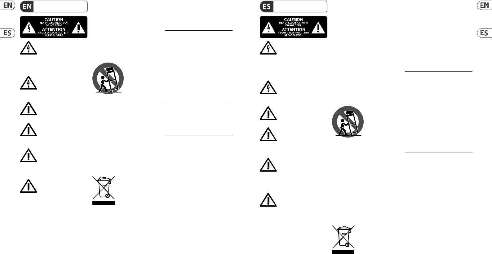
Each fader strip has a mini display screen called a scribble strip. This will indicate information about the current channel/bus number, name and even a graphic icon to quickly identify which channel is currently controlled by the fader and associated buttons. A color bar above the scribble strip allows quick visual identification of groups of related channels. Scribble strip details and color bar options can be edited on the HOME screen/HOME tab by pressing the CUSTOMIZE button.
Pressing the SELECT button directs the control focus of the Main Display and Channel Strip section to that channel or bus. Only one SELECT button can be active at any time.
The SOLO button will isolate that channel for monitoring, along with any other channels or buses that are soloed. The MUTE button mutes the channel currently assigned to that strip.
Stereo level meters provide input level information at a glance, from -60 dB to Clip. The DYNAMICS LED will light whenever the dynamics threshold is exceeded, thus triggering the compressor/expander. Likewise, the GATE LED will light whenever the input signal falls below the noise gate threshold.
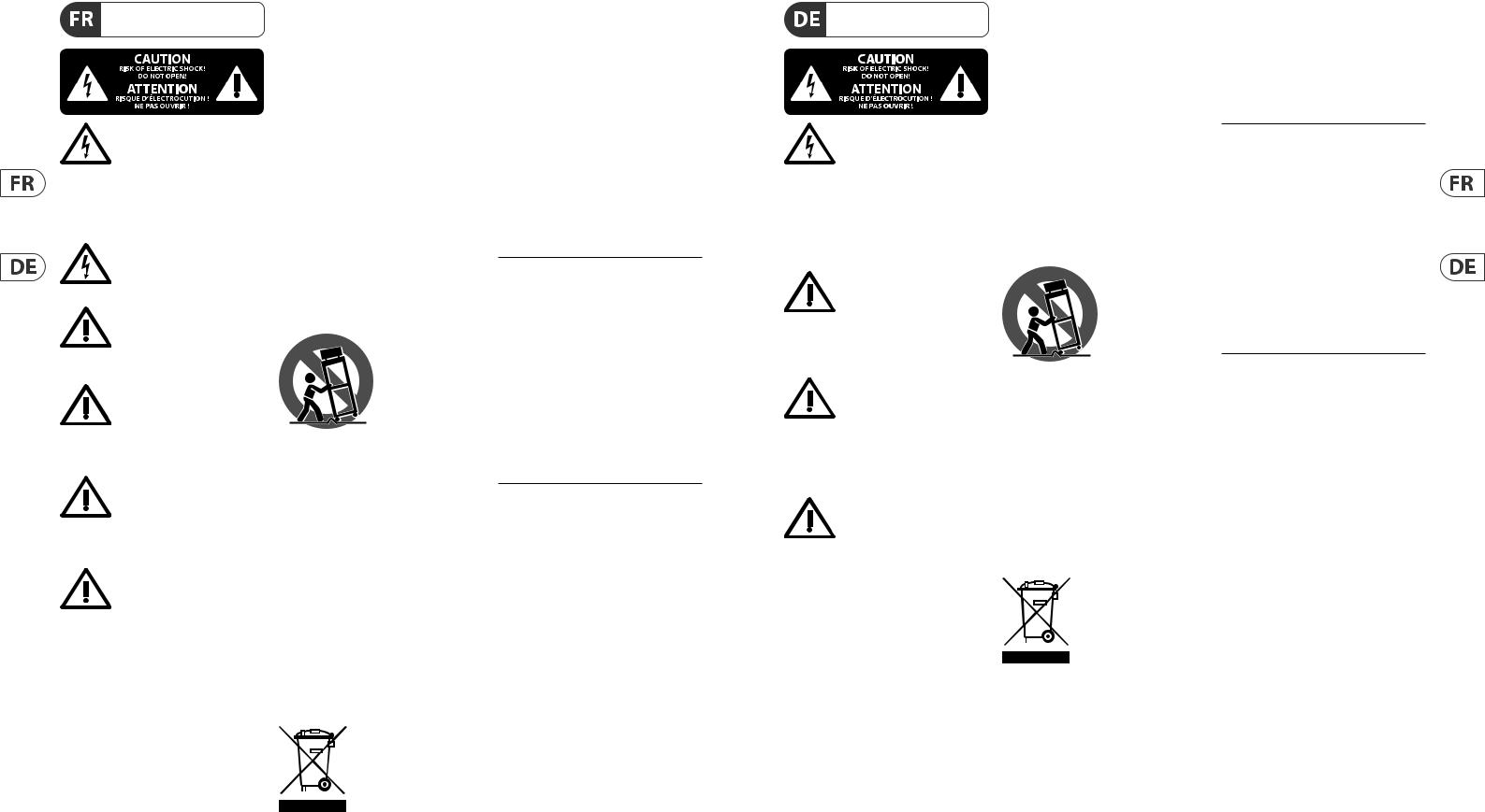
The majority of the WING’s controls can be edited and monitored via the 10" touch screen Main Display. Various screens can be accessed with the 7 buttons along the left side of the screen, as well as the VIEW buttons located in each major section of the top panel.
6 encoders along the bottom of the display allow parameter adjustments of the items shown at the bottom of the current display screen. These are capacitive knobs that will highlight elements on the screen as soon as the associated knob is touched.
An additional 7th encoder to the right of the display can be used for contextdependent control by first touching an item on the Main Display, allowing for finer adjustments compared to moving virtual knobs or faders. A multi-purpose button beneath the 7th encoder performs similarly depending on the current screen.
For example, it can be used as a tap tempo when editing delay effects.
The large stereo meter will either display the main bus or solo bus levels. The CLR SOLO button will release all channels and buses that are active in the solo bus.
An overview of each screen is presented in Chapter 3.
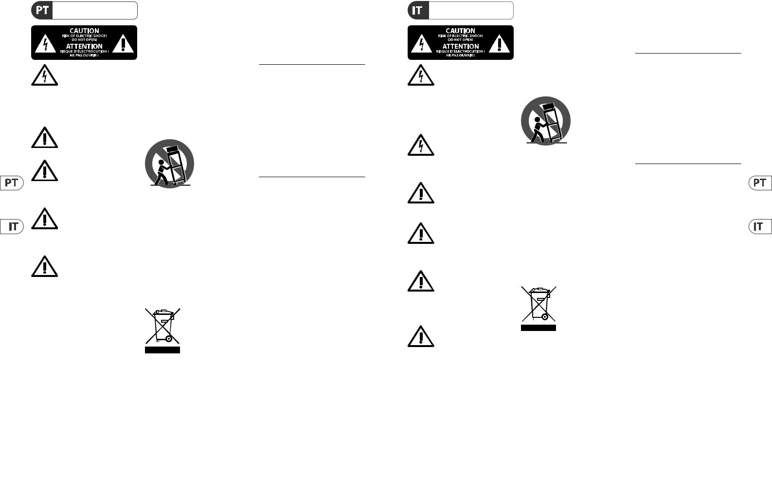
The navigation arrows and value/scrub wheel perform functions pertaining to DAW control as well as the USB Audio and WING-LIVE players. The wheel can also fine-tune values of parameters assigned in the User layer of the Custom Controls while respective buttons are depressed.
Quick Start Guide 11
Channel Strip Section |
4-Channel Section |
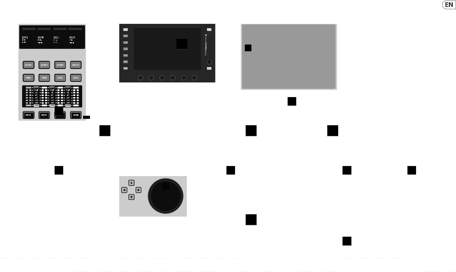
The channel strip provides quick access to the primary parameters for the currently-selected channel. A display screen provides dedicated editing details for the parameter being adjusted, and various indications for input configuration, bus and group assignments, and metering are always visible for convenience.
One of 7 channel editing blocks (including EQ) can be sent to the editing display screen by pressing the associated button or touching the capacitive encoder knob directly above. Press and hold the button to turn the block on or off.
Pressing the VIEW button will open the HOME screen of the selected channel on the Main Display.
Once a block is already active, pressing the block button again will scroll through several parameters for editing, and the associated encoder can be used for adjustments. Small dots in the lower right corner of the display indicate how many parameters can be scrolled through by repeatedly pressing the block button.
An additional EQ section has dedicated controls for adjustment of up to 6 EQ bands for input channels and 8 bands for buses. Engage the EQ block by pressing and holding the EQ button, then touch one of the 4 EQ encoder knobs to select a band for adjustment. Press the SHIFT button to access the low and hi shelf bands, and additional bands if editing a bus EQ.
The GAIN, WIDTH and FREQ buttons select which element of the current band will be adjusted with the encoder.
Press the LISTEN button in the lower right corner to monitor the EQ band in isolation. The BLEND/MIX knob acts as a wet/dry adjustment for the EQ block. This can be used to exaggerate or de-emphasize the current EQ setting.
The edit section above the righthand fader bank offers a special set of dedicated control elements. This can be parameters like gain, pan, filters or effects sends for the selected bank of 4 channels.
Pressing one of the 8 buttons enables the 4 knobs and 4 buttons to control channel properties without actually selecting the channel for editing. This makes the 4-channel section independent from the main control surface, and would allow for a second audio engineer to work in parallel to the FOH engineer.
Custom Controls
The Custom Controls section allows up to 4 rotary knobs and 8 buttons to be configured for control of specific elements that should be available at all times regardless of the main display screen focus. A common use could be the vocal channel’s reverb send level. Presets can also be configured to suit different sets, venues, operators, etc. Press the VIEW button to assign functions to the controls, optimize the scribble strips, or reset the controls.

12 WING
WING Overview
Show/Mute/Transport/Automix Control |
|
AES50/Control/StageCONNECT |
|||||||||||||||||||||||||
|
|
|
|
|
|
|
|
|
|
|
|
|
|
|
|
|
|
|
|
|
|
|
|
|
|
|
|
|
|
|
|
|
|
|
|
|
|
|
|
|
|
|
|
|
|
|
|
|
|
|
|
|
|
|
|
|
|
|
|
|
|
|
|
|
|
|
|
|
|
|
|
|
|
|
|
|
|
|
|
|
|
|
|
|
|
|
|
|
|
|
|
|
|
|
|
|
|
|
|
|
|
|
|
|
|
|
|
|
|
|
|
|
|
|
|
|
|
|
|
|
|
|
|
|
|
|
|
|
|
|
|
|
|
|
|
|
|
|
|
|
|
|
|
|
|
|
|
|
|
|
|
|
|
|
|
|
|
|
|
|
|
|
|
|
|
|
|
|
|
|
|
|
|
|
|
|
|
|
|
|
|
|
|
|
|
|
|
|
|
|
|
|
|
|
|
|
|
|
|
|
|
|
|
|
|
|
|
|
|
|
|
|
|
|
|
|
|
|
|
|
|
|
|
|
|
|
|
|
|
|
|
|
|
|
|
|
|
|
|
|
|
|
|
|
|
|
|
|
|
|
|
|
|
|
|
|
|
|
|
|
|
|
|
|
|
|
|
|
|
|
|
|
|
|
|
|
|
|
|
The bottom portion of the Custom Control section allows quick access to different categories. Press the VIEW button to configure each of them. It offers a combination of user-assignable buttons and pre-configured buttons for controlling the USB recorder, the WING LIVE recorder, Mute Groups and
Show Control.
Rear Panel
Analog I/O
The rear panel analog connections include 8 MIDAS PRO series microphone preamps and 8 XLR outputs, plus 8 balanced ¼” aux input and output connectors. A lamp socket accepts a standard 12 V light. 5-pin MIDI IN and OUT jacks allow external MIDI control, and a pair of ¼”TRS jacks for GPIO allow basic input and output commands.
Power
Connect the included IEC cable.
A pair of Ethernet ports allow a network to be set up via router for wired or wireless control using one of the control apps for PC, phone or tablet. A USB port allows bidirectional 48-channel transmission as well as firmware updates and data exchange. An ASIO driver can be downloaded from behringer.com.
3 AES50 ports can each provide up to 48 input and output channels to and from digital stageboxes, ensuring abundant channel count and allowing patching from multiple locations. The WING is fully compatible with all X32 series mixers and stage boxes.
Cabling for all AES50 connections between WING and stage boxes:
•Shielded CAT-5e cable
•Ethercon terminated cable ends
•Maximum cable length of 80 meters
StageCONNECT is a proprietary connection for transmitting up to 32 audio channels via standard XLR and DMX cable. The interface supports different bus configurations of input and output channels and uses digital, uncompressed PCM at 44.1/48 kHz and 24-bit resolution. StageCONNECT was developed for flexible connections on stage using standard mic cable, supporting a wide range of stage boxes and monitoring systems at sub-millisecond latency.
Stereo AES/EBU input and output connections can be made via XLR cables.
Expansion Slot
The WING ships with the WING-LIVE card installed, which allows up to 64 channels of 48 kHz / 32-bit audio to be recorded onto a pair of SD or SDHC cards.
Other options such as Dante, SoundGrid and MADI will be available for purchase as well.
3. Main Screens
Most of the advanced editing and control is done on the Main Display. Screens can be accessed via the 7 buttons to the left of the screen, or via VIEW buttons in each section of the top panel.
The layout varies greatly from screen to screen, but a fairly permanent status bar can be seen along the top of the screen to provide quick reference for channel name, clock, and alerts. This also allows constant access to the SD card controls, setup menu, library functions and other tools.
HOME
The HOME screen defaults to an overview of the selected channel. This screen allows adjustment of basic parameters like pan and level, but mostly provides a launch point to important processing blocks like EQ and dynamics.
The blocks can be navigated using the left column regardless of which block is currently in view. Note that the processing sequence of gate, dynamics, EQ, and insert can be adjusted by pressing the Edit button at the bottom of the
left column.
The INPUT screen appears second in the left-hand column, though the order of the blocks can be customized on the default/overview screen. The primary and alternate Source that is assigned to the current channel is selected here.
The FILTER screen is also a part of this section, allowing low cut, hi cut and advanced filtering options like tilt filter and all-pass filter for phase alignment.
The GATE screen appears 3rd in the left-hand column, though the order of some blocks can be customized on the HOME overview screen. The block defaults to a simple noise gate with common parameters like threshold and ratio, though many other effects can be selected from the Gate Model menu. This block’s name will change to reflect the chosen model.
The EQ block defaults to a 6-band fully-parametric equalizer for input channels, and 8-band for buses. A variety of EQ models can be selected from the
EQ Model menu.
The DYNAMICS block offers a large selection of generic and legendary compressors, expanders and limiters.
Two INSERT blocks are available by default, one that can be positioned before or after the Gate, EQ and/or Dynamics blocks, and another that is fixed post-fader and input processing.
The MAIN screen allows the send level to each of the 4 Master buses to be adjusted along with the width, pan and level.
The last screen in the left-hand column allows adjustment of send levels to all 16 buses.
The Home screen has a similar appearance when a bus is selected, but no gate block is available and only trim can be adjusted. The bus mode can be set to pre or post-fader if they will be used for monitoring or effects, or subgroup if channels will be routed to the bus prior to the main mix.
EFFECTS
The EFFECTS screen controls all aspects of the 16 effects processors. Users can select from a large collection of effects, configure routing, adjust parameters and monitor levels.
Effects are usually applied to channels in one of two ways – Send-style effects, and Insert effects. Time-based effects like reverb and delay work well as Send effects, whereas modulation or compression effects tend to work better as Inserts so that they can process the entire signal.
Quick Start Guide 13
Send effects are achieved by sending at least one, though often multiple channels to a bus that contains an effect such as reverb. Use one of the Insert points on
the bus to select one of the many reverb effects. The channels are sent to the main output bus along with the bus that carries the effect signal. By varying the amount of signal sent to the effect bus, a proper blend of “dry” signal will appear in the main output along with the “wet” effect signal.
The channel HOME screen is already set up with a couple of Insert points, one of which can be patched at several points in the signal flow. Tap one of the INS blocks in the left-hand column to assign an effect processor. A chorus or flanger effect will probably sound better as an insert rather than a send, and whether the effect goes before or after the EQ and dynamics blocks is a matter of preference.
METERS
The METERS screen displays different groups of level meters for various
signal paths, allowing quick analysis of any channels or buses that might need level adjustment.
ROUTING
The ROUTING screen allows patching and configuration of sources and outputs. Two icons at the top of the Main Display determine whether the page focuses on sources (inputs) or outputs.
Press the pull-down menu to select onboard analog connectors, AES50, USB, WING LIVE, etc. For Source groups, details such as name, color, icon, tags, and mono/stereo/mid-side mode can be configured here.
With outputs selected, the routing can be viewed for each analog or digital output destination. To assign new sources for outputs, first disable the lock function.
SETUP
The SETUP screen allows network configuration for remote control of the console with a PC, tablet or smartphone running one of the dedicated apps.
The screen also allows various global settings and I/O configuration for expansion cards and GPIO. The date and time can also be set on this screen.
The current firmware version is listed in the bottom right corner, which can be updated either via the rear panel USB port, or via a flash drive connected to the top panel port. See the Chapter 6 for details.
LIBRARY
The LIBRARY screen allows the current console state to be saved into Snapshots for later recall. The scope of parameters that are recalled can be specified prior to loading. Global Safes further protect certain areas of the console from being affected by snapshot recall. See Chapter 5 for details.
UTILITY
This button does not have its own screen, but rather works in conjunction with other screens. The function is context relative, so depending on which screen is currently active, pressing the UTILITY button may bring up additional preset options or settings configuration.

14 WING
WING Overview
Additional VIEW-based screens:
INPUT/BUS/MAIN – Pressing the VIEW button in any of the 3 fader sections will bring up an overview screen to monitor all input, bus or output channels at once.
MONITOR – Even though the top panel Monitor section has some hardware controls, a significant amount of configuration is available via the VIEW button to determine where Talkback paths are heard, monitor A and B sources, monitor bus EQ and metering, dimming levels, and more.
CHANNEL STRIP – The VIEW button in the Channel Strip will call up a screen relevant to the block that is currently being edited. All of the screens that are accessed with the Channel Strip VIEW button are also accessible via the Main Display HOME button, but provide more immediate access.
CUSTOM CONTROLS – The top and bottom portions of the Custom Control section each have their own VIEW button to edit the functions that are controlled by the hardware elements.
4. Patching and Setup
To help understand the basics of patching and signal flow, here is an example scenario that might be common for a live music event. In this hookup, the audio sources on stage are connected to an S16 stage box which sends the signals via shielded ethernet cable to the WING’s AES50-A port. The physical connections to the stage box are a bit disorganized, but this can be repatched in the console in a more standardized way.
S16 Input |
Physical |
Source |
Channel |
||
|
Connection |
|
Assignment |
||
1 |
Bass guitar DI |
AES-A 1 |
7 |
|
|
2 |
Lead guitar |
AES-A 2 |
8 |
|
|
|
|
|
|
|
|
3 |
Keyboard L |
AES-A 3/L (linked) |
10 |
(stereo) |
|
|
|
|
|
|
|
4 |
Keyboard L |
AES-A 4/R |
10 |
(automatic) |
|
5 |
Backing track L |
AES-A 5/L (linked) |
11 |
(stereo) |
|
|
|
|
|
|
|
6 |
Backing track R |
AES-A 6/R |
11 |
(automatic) |
|
|
|
|
|
|
|
7 |
Vocal stage R |
AES-A 7 |
12 |
|
|
8 |
Kick drum |
AES-A 8 |
1 |
|
|
|
|
|
|
|
|
9 |
Tom 1 |
AES-A 9 |
2 |
|
|
|
|
|
|
|
|
10 |
Tom 2 |
AES-A 10 |
3 |
|
|
11 |
Tom 3 |
AES-A 11 |
4 |
|
|
|
|
|
|
|
|
12 |
Snare |
AES-A 12 |
5 |
|
|
|
|
|
|
|
|
13 |
Overhead 1 |
AES-A 13/L (linked) |
6 |
(stereo) |
|
14 |
Overhead 2 |
AES-A 14/R |
6 |
(automatic) |
|
|
|
|
|
|
|
15 |
Vocal stage L |
AES-A 15 |
13 |
|
|
|
|
|
|
|
|
16 |
Acoustic DI |
AES-A 16 |
9 |
|
|
|
|
|
|
|
|
The Source is what gives meaning and identity to an input, which makes patching WING Sources to channels very evident and clear.
Press the ROUTING button and touch the pull-down menu at the top of the screen. Select ‘AES50 A’ from the list of input groups. Press the ‘A 1’ square, which will allow the Source details to be defined, including the name, icon, color, phantom power, and even preliminary gain adjustment. If a pair of Sources should be linked as stereo or mid-side, this can be done as well. Note that the odd-numbered Source will always occupy the left side, and the even-numbered Source direct above it will occupy the right. Be sure to arrange your physical
connections accordingly.
Press the HOME button on the Main Display and then the SELECT button for channel 1 in the first fader bank. If no Source is selected, no gain adjustment can be made. Press ‘INPUT’ on the HOME screen, or navigate to the second tab in the left-hand column. Press the Source Select square under the MAIN section and select AES50 A from the pull-down menu. Tap ‘A 8’ in the grid to assign the
kick drum to channel 1.
Without leaving this page, press the SELECT button for channel 2 in the first fader bank. Select AES50 A-9 to assign Tom 1 to channel 2. Continue through the other channels to assign the otherwise messy physical connections at the stage box in a logical and organized manner. When assigning the overhead mics to channel 6, pressing AES 13/L will automatically route both mic signals to channel 6 in stereo.
On the ROUTING screen, press the output icon at the top of the screen. Touch the Output Group pull-down menu and select ‘AES50 A’. Press the first square in the grid. Touch the Input Group pull-down menu and select BUS. Select 1L to assign bus 1 to XLR output 1 on the S16. Repeat this process for any other bus sends back to the stage. When editing output 7 and 8, select MAIN from the Input Group menu, then assign 1L to output 7 and 1R to output 8. These outputs will be connected to your power amplifiers or active main speakers.
Note – when using mono stage wedges, use the Mono button in the input section to set width to 0.
Quick Start Guide 15
5. Presets and Snapshots Library
After putting in the effort to adjust the routing, channel processing and global preferences, it is highly recommended that a Snapshot be created to preserve the console state. This can be done in the Library section. Many options exist to select both the way that these are saved, as well as how the console state is protected when loading previously-saved Snapshots.
The left-hand pane of the Snapshot Library will show a list of your Snapshots that have been saved to the main directory, as well as any folders that you have created to organize similar Snapshots. If many Snapshots are likely to be saved, or if multiple engineers will be using the console, then it may be more efficient to make good use of folders.
Recall Scope
Various elements of the console, including routing, channel processing, and global configuration can be selected or omitted both when saving and recalling a saved Snapshot. Channels, buses and FX engines will expand for easier select/deselect. Adjusting the recall scope prior to saving can act as a reminder to the purpose for that Snapshot being saved in the first place. When a saved Snapshot is selected from the library list, the state of the recall scope at the time the Snapshot was saved will be displayed. This also allows the scope to be further adjusted
before loading.
When the Snapshot is loaded, only the elements highlighted in blue will be affected.
Global Safes
Touch the GLOBAL SAFES button at the top of the screen to access these options. Certain elements can be protected from ever being affected by Snapshot recall. To summarize:
Blue – channel/routing/config will be recalled when a saved Snapshot is loaded. Grey – Specific element will not be recalled when a saved Snapshot is loaded.
Red – Highlighted element will never be affected by Snapshots because a Safe is active.
Transferring Libraries to a PC
A Library of Snapshots and Presets is stored in the internal DATA file system of your WING. This file system can be made available to connected personal computers for transferring, copying and exchanging data.
•Open the SETUP/Global Settings Edit page and enable DATA ACCESS.
•Connect a USB cable to the rear panel port and to your computer.
•A virtual drive will appear on your computer, similar to connecting a flash drive or external hard drive. Double click the drive to open.
•Any stored Snapshots and Presets will show up and can be copied to the PC.
6. Firmware Updates
The WING console firmware can be easily updated via USB. Download the firmware file from the product page on Behringer.com and follow these steps.
•Open the Setup/Global Edit page and enable OS ACCESS.
•Connect a USB cable to the rear panel port and to your computer.
•A virtual drive will appear on your computer, similar to connecting a flash drive or external hard drive. Double click the drive to open.
•Drag the new firmware file into the drive.
Note, although WING will always boot using the most recent firmware
in that drive, it is recommended to delete older firmware files or move them to a subfolder.
If the console does not boot up normally, you can still update the firmware using this procedure:
•With console powered off, connect a USB cable to the rear panel port and to your computer.
•Press and hold the Select button next to the Main Display, then power the console on.
•An OS and DATA drive will appear on your computer, similar to connecting a flash drive or external hard drive. Double click a drive to open.
•Drag the new firmware file into the OS drive.
•Note, WING will always boot using the most recent firmware in that drive.
•After the file has transferred, eject the virtual drive. The console should reboot automatically with the new firmware installed. If it doesn’t, power cycle the console manually.
Initialize to Default Settings
You can reset the console to its initial state if you need to ensure that no previous settings are interfering with what you plan to set up from scratch. There are two ways to achieve this:
>by opening the Setup/Global Edit page and selecting INIT CONSOLE.
>by pressing and holding the CLEAR SOLO button on the Main Display while powering the console up.
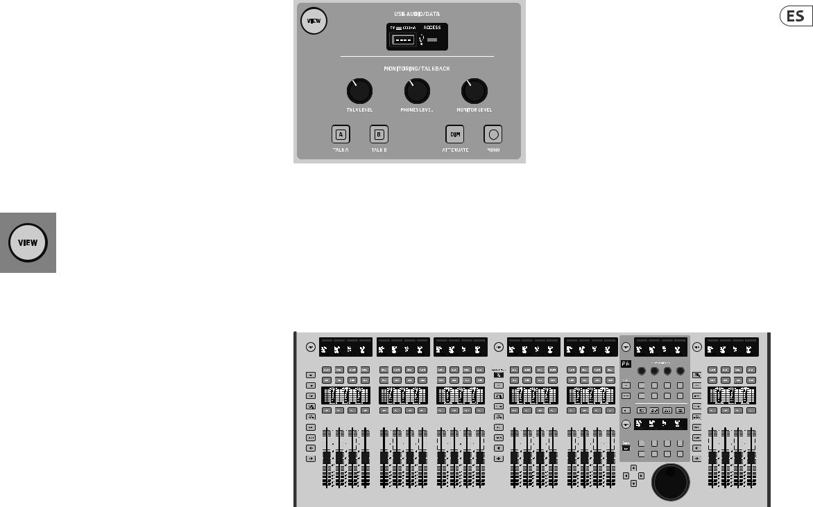
16 WING
Resumen del WING
1. Introducción
Felicidades y gracias por su compra de esta innovadora mesa de mezclas y bienvenido al Manual de puesta en marcha de la WING. Hemos desarrollado esta mesa a partir de nuestra famosa plataforma X32 de cara a ofrecer al mundo del audio una unidad que amplíe sus posibilidades y facilidad de uso en todas sus formas. Lea este manual para ver un resumen completo de las funciones de la WING y no deje de visitar la web behringer.com para ver más guías y videos con tutoriales sobre ella.
Pasos previos
Las primeras unidades enviadas de la mesa WING estaban equipadas con una versión inicial del firmware que lo más seguro es que haya sido actualizada para cuando la unidad llegue a los compradores. Si está leyendo esto quiere decir que es uno de los pocos privilegiados que ha puesto sus manos sobre una de estas primeras unidades y que podrá beneficiarse de las nuevas ventajas.
Le recomendamos que acceda a la web periódicamente para ver si hay nuevas actualizaciones de firmware, dado que estas nuevas versiones incluirán nuevas funciones y la solución a problemas detectados. Nuestro equipo de desarrollo está deseando reaccionar ante las sugerencias de nuestros clientes tanto como sorprenderles con mejoras y nuevas funciones. Visite la página de producto en la web behringer.com para descargarse la última versión de firmware y disfrutar de todo el potencial de su WING.
Consulte en el capítulo 6 de este Manual los detalles acerca del proceso de actualización.
Fuente y canal – un nuevo punto de vista acerca del ruteo
La WING lleva el concepto de etiquetar los canales con nombres, iconos y colores un paso más allá hasta la Fuente real. La combinación y ajuste del balance del ratio entre las fuentes audio es el concepto fundamental del proceso de mezcla. No se trata del canal, en el que es aplicado el procesado audio, es la Fuente lo que importa en primer térmico. De ahí que las Fuentes WING comprendan una entrada concreta, sus parámetros de previo como ganancia, mute y alimentación fantasma, el modo mono/stereo/centro-lateral, un nombre, icono y color y etiquetas definibles por el usuario.
Estas Fuentes pueden ser usadas por uno o varios canales para aplicarles un procesado y enviar el audio a buses o salidas principales. También pueden ser rutadas a cualquier salida de forma directa cuando no quiera aplicarles ningún procesado, tal como en montajes para grabación o cuando comparta la señal audio con otras mesas para mezclas independientes.
Para resumir:
Fuentes – Son técnicamente cualquier punto de entrada de audio a la consola. Una entrada puede ser una conexión analógica XLR o de 6,3 mm del panel trasero, señales desde una unidad de escenario, conexión USB, tarjeta de expansión, etc. Estas fuentes son los puntos básicos para cualquier procesado audio y ruteo en el WING. Las Fuentes incluyen características identificativas como el nombre, color, icono y etiqueta, y también disponen de su propia ganancia, ajuste de anulación o mute, alimentación fantasma y modo mono/stereo/centro-lateral para esa entrada.
48 canales de entrada mono/stereo – Cada canal de entrada puede ser conectado a una salida principal (Main) y a una Fuente alternativa. Los canales del WING permiten la aplicación de un procesado extremadamente potente
y flexible a la Fuente audio. Estos canales pueden heredar las propiedades de personalización de la Fuente como pueden ser el nombre, icono, color y etiqueta. Estos canales usarán automáticamente el audio de entrada en mono o stereo dependiendo del modo de la Fuente y ya no es necesario enlazar los canales en un par stereo. El audio de los canales puede ser enviado a los buses o salidas principales para su mezcla, o pueden ser extraído directamente de forma individual para su conexión a salidas.
16 buses stereo y 4 salidas principales stereo – Los 16 Buses se usarán habitualmente para el procesado por efectos de tipo envío o la monitorización de mezcla, y serán enviados habitualmente a una de las 4 salidas principales. Ambos buses y las salidas principales pueden ser enviados a la Matriz, Señales de usuario o destinos de salida.
8 buses de matriz – Los buses de matriz pueden ser enviados las señales de usuario o a los destinos de salida, y se usan habitualmente para submezclas o mezclas de zona.
Salidas - Dispone de una amplia gama de destinos analógicos y digitales a los que pueden ser enviadas las señales audio de Fuente pura o mezclada, una vez procesadas—sin ninguna restricción.
Vea en el capítulo 4: Interconexión y configuración más detalles y un ejemplo de posible escenario.
2. Descripciones del hardware
Botones VIEW
Cada una de las secciones principales del panel superior de la mesa dispone de un botón llamado VIEW. La pulsación de cualquiera de ellos hará que la pantalla principal cambie su indicación a una pantalla específica relativa a la sección en la que haya pulsado el botón VIEW. Esta pantalla principal le ofrecerá habitualmente
parámetros, opciones o información adicional que no es accesible habitualmente a través del panel superior solo.
Mientras está activo, cada botón VIEW se ilumina en verde. El pulsar de nuevo el mismo botón VIEW hará que la pantalla principal vuelva a la pantalla que estaba activa antes de pulsar el botón y que el botón VIEW se apague. El desplazarse manualmente a otra pantalla diferente a la elegida con un botón VIEW hará también que dicho botón atenúe su brillo.
En algunos casos, la pulsación de un botón VIEW será simplemente un atajo a una pantalla a la que podría llegar de todas maneras navegando a partir de la pantalla principal, pero en otros casos la pulsación de ese botón será la única forma de acceder a esa pantalla.
Algunos de los botones VIEW admiten una función de mantenimiento de pulsación que da acceso a una página adicional de configuración. Por ejemplo, el mantener pulsado cualquiera de los botones VIEW del banco de fader le dará acceso a la pantalla de edición en la que podrá redistribuir los canales y buses.
El botón VIEW de la sección de banda de canal que está a la derecha de la pantalla principal actuará junto con los 6 botones de bloque que están dentro de esa sección (Input, Filter, Gate, etc). Estos botones actúan como atajos a páginas dentro de la pantalla principal, por lo que muy pocas de las funciones habituales estarán a más de una pulsación de botón de distancia.
Quick Start Guide 17
Monitorización/línea interna o talkback/USB
Un conector USB de tipo A permite la conexión directa de una unidad flash a la consola para el almacenamiento y carga de datos. Esto le permitirá tener siempre una copia de seguridad de los ficheros de sus shows o incluso usar una mesa WING de alquiler manteniendo su configuración habitual. El conector le permite también
la grabación y reproducción de ficheros audio. El puerto permite la carga de un dispositivo portátil como un móvil o tablet, lo que resulta muy útil si utiliza de forma habitual uno de estos dispositivos para la mezcla.
La sección tiene también mandos de nivel específicos para las salidas de auriculares (situadas en la parte inferior del extremo superior) y las salidas de monitor (que son por defecto la salida Aux 7/8 del panel trasero). La activación del botón DIM reduce el volumen de monitorización y el botón MONO hace que las señales queden sumadas en mono.
El nivel del micro de línea interior o talkback puede ser ajustado con el mando TALK LEVEL y los botones TALK A y B envían la señal de línea interior a diferentes destinos. Puede usar el canal 40 o el auxiliar 8 como entrada para el canal de línea interior.
Pulse el botón VIEW para controlar los ajustes de monitor, ajustar la cantidad de atenuación Dim, elegir el ruteo para el micro talkback y otros parámetros.
Secciones de fader
|
|
|
|
|
|
|
|
|
|
|
|
Input channels |
|
|
Bus/DCA/Matrix |
|
|
Main/Matrix |
|||||||||||||||||||||||||||||||||||||||||||||||||||||||||||||||||||
|
|
|
|
|
|
|
|
|
|
|
|
|
|
|
|
|
|
|
|
|
|
|
|
|
|
|
|
|
|
|
|
|
|
|
|
|
|
|
|
|
|
|
|
|
|
|
|
|
|
|
|
|
|
|
|
|
|
|
|
|
|
|
|
|
|
|
|
|
|
|
|
|
|
|
|
|
|
|
|
|
|
|
|
|
|
|
|
|
|
|
|
|
|
|
|
|
|
|
|
|
|
|
|
|
|
|
|
|
|
|
|
|
|
|
|
|
|
|
|
|
|
|
|
|
|
|
|
|
|
|
|
|
|
|
|
|
|
|
|
|
|
|
|
|
|
|
|
|
|
|
|
|
|
|
|
|
|
|
|
|
|
|
|
|
|
|
|
|
|
|
|
|
|
|
|
|
|
|
|
|
|
|
|
|
|
|
|
|
|
|
|
|
|
|
|
|
|
|
|
|
|
|
|
|
|
|
|
|
|
|
|
|
|
|
|
|
|
|
|
|
|
|
|
|
|
|
|
|
|
|
|
|
|
|
|
|
|
|
|
|
|
|
|
|
|
|
|
|
|
|
|
|
|
|
|
|
|
|
|
|
|
|
|
|
|
|
|
|
|
|
|
|
|
|
|
|
|
|
|
|
|
|
|
|
|
|
|
|
|
|
|
|
|
|
|
|
|
|
|
|
|
|
|
|
|
|
|
|
|
|
|
|
|
|
|
|
|
|
|
|
|
|
|
|
|
|
|
|
|
|
|
|
|
|
|
|
|
|
|
|
|
|
|
|
|
|
|
|
|
|
|
|
|
|
|
|
|
|
|
|
|
|
|
|
|
|
|
|
|
|
|
|
|
|
|
|
|
|
|
|
|
|
|
|
|
|
|
|
|
|
|
|
|
|
|
|
|
|
|
|
|
|
|
|
|
|
|
|
|
|
|
|
|
|
|
|
|
|
|
|
|
|
|
|
|
|
|
|
|
|
|
|
|
|
|
|
|
|
|
|
|
|
|
|
|
|
|
|
|
|
|
|
|
|
|
|
|
|
|
|
|
|
|
|
|
|
|
|
|
|
|
|
|
|
|
|
|
|
|
|
|
|
|
|
|
|
|
|
|
|
|
|
|
|
|
|
|
|
|
|
|
|
|
|
|
|
|
|
|
|
|
|
|
|
|
|
|
|
|
|
|
|
|
|
|
|
|
|
|
|
|
|
|
|
|
|
|
|
|
|
|
|
|
|
|
|
|
|
|
|
|
|
|
|
|
|
|
|
|
|
|
|
|
|
|
|
|
|
|
|
|
|
|
|
|
|
|
|
|
|
|
|
|
|
|
|
|
|
|
|
|
|
|
|
|
|
|
|
|
|
|
|
|
|
|
|
|
|
|
|
|
|
|
|
|
|
|
|
|
|
|
|
|
|
|
|
|
|
|
|
|
|
|
|
|
|
|
|
|
|
|
|
|
|
|
|
|
|
|
|
|
|
|
|
|
|
|
|
|
|
|
|
|
|
|
|
|
|
|
|
|
|
|
|
|
|
|
|
|
|
|
|
|
|
|
|
|
|
|
|
|
|
|
|
|
|
|
|
|
|
|
|
|
|
|
|
|
|
|
|
|
|
|
|
|
|
|
|
|
|
|
|
|
|
|
|
|
|
|
|
|
|
|
|
|
|
|
|
|
|
|
|
|
|
|
|
|
|
|
|
|
|
|
|
|
|
|
|
|
|
|
|
|
|
|
|
|
|
|
|
|
|
|
|
|
|
|
|
|
|
|
|
|
|
|
|
|
|
|
|
|
|
|
|
|
|
|
|
|
|
|
|
|
|
|
|
|
|
|
|
|
|
|
|
|
|
|
|
|
|
|
|
|
|
|
|
|
|
|
|
|
|
|
|
|
|
|
|
|
|
|
|
|
|
|
|
|
|
|
|
|
|
|
|
|
|
|
|
|
|
|
|
|
|
|
|
|
|
|
|
|
|
|
|
|
|
|
|
|
|
|
|
|
|
|
|
|
|
|
|
|
|
|
|
|
|
|
|
|
|
|
|
|
|
|
|
|
|
|
|
|
|
|
|
|
|
|
|
|
|
|
|
|
|
|
|
|
|
|
|
|
|
|
|
|
|
|
|
|
|
|
|
|
|
|
|
|
|
|
|
|
|
|
|
|
|
|
|
|
|
|
|
|
|
|
|
|
|
|
|
|
|
|
|
|
|
|
|
|
|
|
|
|
|
|
|
|
|
|
|
|
|
|
|
|
|
|
|
|
|
|
|
|
|
|
|
|
|
|
|
|
|
|
|
|
|
|
|
|
|
|
|
|
|
|
|
|
|
|
|
|
|
|
|
|
|
|
|
|
|
|
|
|
|
|
|
|
|
|
|
|
|
|
|
|
|
|
|
|
|
|
|
|
|
|
|
|
|
|
|
|
|
|
|
|
|
|
|
|
|
|
|
|
|
|
|
|
|
|
|
|
|
|
|
|
|
|
|
|
|
|
|
|
|
|
|
|
|
|
|
|
|
|
|
|
|
|
|
|
|
|
|
|
|
|
|
|
|
|
|
|
|
|
|
|
|
|
|
|
|
|
|
|
|
|
|
|
|
|
|
|
|
|
|
|
|
|
|
|
|
|
|
|
|
|
|
|
|
|
|
|
|
|
|
|
|
|
|
|
|
|
|
|
|
|
|
|
|
|
|
|
|
|
|
|
|
|
|
|
|
|
|
|
|
|
|
|
|
|
|
|
|
|
|
|
|
|
|
|
|
|
|
|
|
|
|
|
|
|
|
|
|
|
|
|
|
|
|
|
|
|
|
|
|
|
|
|
|
|
|
|
|
|
|
|
|
|
|
|
|
|
|
|
|
|
|
|
|
|
|
|
|
|
|
|
|
|
|
|
|
|
|
|
|
|
|
|
|
|
La WING tiene 3 secciones de fader con sus propios botones de banco asociados. El grupo de 12 faders que está en el lado izquierdo de la consola está destinado principalmente para los canales de entrada, el grupo de 8 faders del centro se usa habitualmente para controlar los buses y DCAs, y el pequeño grupo de 4 faders que están a la derecha se usa principalmente para las salidas principales o de matriz. No obstante, no hay limitaciones a la hora de configurar los bancos de faders. Para acceder a la configuración del banco de fader, mantenga pulsado el botón VIEW de una de las secciones de faders.
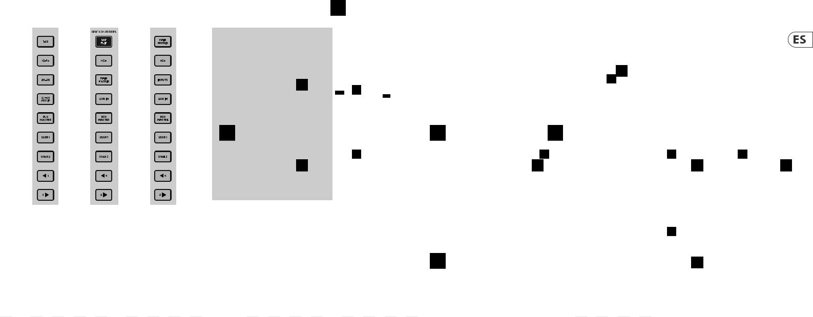
18 WING |
|
|
Quick Start Guide 19 |
Resumen del WING |
|
|
|
Botones de capa/banco |
Bandas de nombre, medidores, selector |
Pantalla principal |
Sección de banda de canal |
La selección de diferentes bancos hará que de forma inmediata un nuevo grupo de canales quede en la sección de fader asociada, incluyendo los nombres de banda/iconos, y que los faders motorizados pasen directamente a sus posiciones correctas. Si un banco concreto no cabe completo en los faders físicos disponibles de una sección (por ejemplo, Bus Masters), las flechas de desplazamiento harán que se mueva en bloques de 4 para acceder a los canales restantes. Cada sección de fader tiene también 2 bancos definibles por el usuario que pueden contener distintos canales.
Para la monitorización de la mezcla, dispone de una función muy útil llamada Sends on Faders (envíos en faders) que le permite ajustar rápidamente los niveles de envío de canal a un bus concreto.
•Pulse el botón SOF FLIP para activar la función Sends on Faders. Los botones MUTE de todos los envíos (bandas de fader de canal de entrada) estarán activos por defecto para proteger los buses en el modo de subgrupo.
•Asegúrese de que el botón BUS MASTERS esté iluminado en la sección de fader de bus y pulse entonces uno de los botones SELECT para identificar el bus al que serán enviadas las señales de canal.
•Suba los faders de canales de entrada para cada uno de los canales que quiera enviar a ese bus, desplazándose por los distintos bancos de entrada si es necesario.
Recuerde desactivar el botón SOF FLIP cuando quiera volver al modo de mezcla normal.
Cada banda de fader tiene una pequeña pantalla llamada banda de nombre. Esta pantalla le indicará información acerca del canal/número de bus activo, nombre e incluso un icono gráfico para identificar rápidamente qué canal es controlado en ese momento por el fader y sus botones asociados. Una barra de color encima de esta banda de nombre le ofrece una rápida identificación visual de los grupos de canales relacionados. Los detalles de la banda de nombre y las opciones de la barra de color pueden ser editados en la pantalla HOME/pestaña HOME pulsando el botón CUSTOMIZE.
El pulsar el botón SELECT hace que el foco del control de la pantalla principal y de la sección de banda de canal se dirija a ese canal o bus. Sólo puede estar activo un botón SELECT a la vez.
El botón SOLO aislará ese canal para la monitorización, junto con el resto de canales o buses activados como solistas. El botón MUTE anula el canal asignado en ese momento a esa banda.
Los medidores de nivel stereo le ofrecen información del nivel de entrada de forma rápida, desde -60 dB a Clip (saturación). El piloto DYNAMICS se iluminará siempre que el umbral de dinamismo sea superado, lo que hará que se active el compresor/expansor. De la misma forma, el piloto GATE se iluminará siempre que la señal de entrada caiga por debajo del umbral fijado para la puerta de ruidos.
La mayoría de los controles de la WING pueden ser monitorizados y editados a través de la pantalla principal de la pantalla táctil de 10 pulgadas de la unidad. Puede acceder a diversas pantallas con los 7 botones que están en el lado izquierdo de esta ventana, así como con los botones VIEW disponibles en cada una de las secciones principales del panel superior.
6 mandos giratorios en la parte inferior de la pantalla permiten el ajustes de los parámetros de los elementos que aparecen en la parte inferior de la pantalla activa. Estos son mandos capacitivos que harán que el elemento de pantalla quede resaltado tan pronto como toque el mando asociado.
Puede usar un 7º mando adicional situado a la derecha de la pantalla para un control variable en base a contexto que podrá ser activado pulsando primero sobre un elemento en la pantalla principal, lo que permitirá ajustes más precisos en comparación con el giro de los mandos virtuales o faders. Un botón multiusos debajo de este 7º mando giratorio realizará una función similar dependiendo de la pantalla activa. Por ejemplo, puede usarlo como un botón de marcación de tempo (tap tempo) durante la edición de efectos de retardo.
El gran medidor stereo le mostrará los niveles de bus solista o de bus principal. El botón CLR SOLO desactivará todos los canales y buses que estén activos en el bus solista.
En el capítulo 3 podrá ver un resumen de cada pantalla.
Las flechas de navegación y la rueda de valores/barrido realizan diversas funciones correspondientes al control DAW así como a los reproductores USB Audio y
WING-LIVE. Esta rueda también permite el ajuste preciso de valores de parámetros asignados en la capa de usuario de los controles personalizados cuando pulse los respectivos botones.
La banda de canal le ofrece un acceso rápido a los parámetros principales del canal activo en ese momento. Una pantalla le ofrece detalles de edición específicos para el parámetro que esté ajustando y diversas indicaciones para la configuración de entrada, asignación de bus y grupo. También dispone siempre de medidores para una mayor comodidad.
Puede enviar uno de los 7 bloques de edición de canal (incluyendo EQ) a la pantalla de edición con solo pulsar el botón asociado o tocar el mando giratorio capacitivo que está justo encima. Mantenga pulsado el botón para activar o desactivar el bloque. El pulsar el botón VIEW hará que aparezca en la pantalla principal la pantalla HOME del canal seleccionado.
Una vez que un bloque ya esté activo, el pulsar el botón de bloque de nuevo hará que vaya pasando por distintos parámetros para su edición, y podrá usar el
mando giratorio asociado para realizar ajustes en ellos. Los pequeños puntos en la esquina inferior derecha de la pantalla le indican a través de cuántos parámetros puede pasar con la pulsación repetida del botón de bloque.
Una sección de EQ adicional dispone de controles específicos para el ajuste de hasta 6 bandas EQ para los canales de entrada y 8 bandas para los buses. Active este bloque EQ manteniendo pulsado el botón EQ y pulse después uno de los 4 mandos EQ para elegir una banda para su ajuste. Pulse el botón SHIFT
para acceder a las bandas de estantería de graves y agudos, así como a bandas adicionales si está editando un EQ de bus.
Los botones GAIN, WIDTH y FREQ le permiten elegir qué elemento de la banda activa será ajustado con el mando giratorio.
Pulse el botón LISTEN de la esquina inferior derecha para monitorizar la banda EQ de forma aislada. El mando BLEND/MIS actúa como un ajuste húmedo/seco para el bloque EQ. Puede usar esto para exagerar o desenfatizar el ajuste EQ activo.
20 WING
Resumen del WING
Sección de 4 canales |
|
|
|
|
|
Control Show/Mute/Transport/Automix |
|
|||||||||||||||||
|
|
|
|
|
|
|
|
|
|
|
|
|
|
|
|
|
|
|
|
|
|
|
|
|
|
|
|
|
|
|
|
|
|
|
|
|
|
|
|
|
|
|
|
|
|
|
|
|
|
|
|
|
|
|
|
|
|
|
|
|
|
|
|
|
|
|
|
|
|
|
|
|
|
|
|
|
|
|
|
|
|
|
|
|
|
|
|
|
|
|
|
|
|
|
|
|
|
|
|
|
|
|
|
|
|
|
|
|
|
|
|
|
|
|
|
|
|
|
|
|
|
|
|
|
|
|
|
|
|
|
|
|
|
|
|
|
|
|
|
|
|
|
|
|
|
|
|
|
|
|
|
|
|
|
|
|
|
|
|
|
|
|
|
|
|
|
|
|
|
|
|
|
|
|
|
|
|
|
|
|
|
|
|
|
|
|
|
|
|
|
|
|
|
|
|
|
|
|
|
|
|
|
|
|
|
|
|
|
|
|
|
|
|
|
|
|
|
|
|
|
|
|
|
|
|
|
|
|
|
|
|
|
|
|
|
|
|
|
|
|
|
|
|
|
|
|
|
|
|
La parte inferior de la sección de controles personalizados le permite un acceso rápido a distintas categorías. Pulse el botón VIEW para configurar cada una
de ellas. Le ofrece una combinación de botones programables por el usuario y botones preconfigurados para el control de la grabadora USB, la grabadora WING LIVE, grupos de anulación o Mute y control de show.
La sección de edición que está sobre el banco de faders de la derecha le ofrece un grupo especial de elementos de control específicos. Pueden ser parámetros como ganancia (gain), panorama (pan), filtros o efectos de envío para el banco seleccionado de 4 canales.
El pulsar uno de los 8 botones activa los 4 mandos y 4 botones que le permiten controlar propiedades de canal sin elegir realmente el canal para su edición. Esto hace que la sección de 4 canales sea independiente de la superficie de control principal, lo que podría permitir que un segundo técnico de sonido trabajase en paralelo con el técnico FOH.
Controles personalizados
Esta sección de controles personalizados le permite configurar 4 mandos giratorios y 8 botones para que controlen elementos concretos que estarán disponibles en todo momento independientemente del foco de la pantalla principal. Un uso habitual podría ser el nivel de envío de reverb del canal vocal. También puede configurar presets para adaptarlo a distintas necesidades, escenarios, locales, técnicos, etc. Pulse el botón VIEW para asignar funciones a los controles, optimizar las bandas de texto o reiniciar los controles.
Quick Start Guide 21
Panel trasero
E/S analógica
Las conexiones analógicas del panel trasero incluyen 8 previos de micro MIDAS PRO series y 8 salidas XLR, además de 8 conectores de entrada y salida auxiliar balanceada en 6,3 mm. Un conector para flexo permite la conexión de una lámpara o flexo standard de 12 V. Clavijas MIDI IN y OUT de 5 puntas permiten el control MIDI externo, y un par de clavijas TRS de 6,3 mm para GPIO permiten la entrada y salida básica de órdenes.
Power
Conecte aquí el cable de alimentación IEC incluido.
AES50/Control/StageCONNECT
Un par de puertos Ethernet le permiten configurar una red vía router para el control por cable o inalámbrico usando una de las apps de control para PC, móvil o tablet. Un puerto USB permite la transmisión bidireccional de 48 canales, así como actualizaciones de firmware e intercambio de datos. Puede descargar un driver ASIO desde behringer.com.
Cada uno de los 3 puertos AES50 le ofrece hasta 48 canales de entrada y salida a y desde unidades de escenario digitales, lo que le asegura suficiente capacidad de canales para cualquier cosa y le permite la interconexión desde distintas ubicaciones. El WING es totalmente compatible con todos los mezcladores y unidades de escenario de la serie X32.
Cableado para todas las conexiones AES50 entre el WING y las unidades de escenario:
•Cable CAT-5e blindado
•Terminación Ethercon en los extremos
•Longitud máxima del cable 80 metros
La StageCONNECT es una conexión exclusiva para la transmisión de hasta 32 canales audio a través de un cable standard XLR y DMX. Este interface admite diferentes configuraciones de bus de canales de entrada y salida y usa una señal PCM digital sin compresión a 44.1/48 kHz y con una resolución de 24 bits. Este StageCONNECT fue desarrollado para unas conexiones muy flexibles sobre el escenario usando cable de micro standard y permitirle el uso de una amplia gama de unidades de escenario y sistemas de monitorización, todo ello con una latencia por debajo de un milisegundo.
Puede realizar conexiones de entrada y salida stereo AES/EBU a través de cables XLR.
Ranuras de expansión
El WING viend de fábrica con la tarjeta WING-LIVE instalado, que permite la grabación de hasta 64 canales de audio a 48 kHz / 32 bits en un par de tarjetas SD o SDHC. También puede adquirir de forma opcional otras opciones como Dante, SoundGrid y MADI.
 Loading...