


 Loading...
User Manual
X32 CORE DIGITAL RACK MIXER
40-Input, 25-Bus Digital Rack Mixer with AES50 Networked Audio, USB Audio Interface and iPad/iPhone Remote Control

2 |
X32 CORE DIGITAL RACK MIXER User Manual |
|
Table of Contents |
|
|
Important Safety Instructions....................................... |
3 |
|
Legal Disclaimer.............................................................. |
3 |
|
Limited warranty............................................................ |
3 |
|
Introduction.................................................................... |
4 |
|
1. Callouts........................................................................ |
5 |
|
2. Hookup........................................................................ |
6 |
|
3. Select Knob Functions............................................... |
8 |
|
4. FX Descriptions......................................................... |
10 |
|
5. Topic Guide............................................................... |
16 |
|
|
5.1 Firmware updates.............................................................. |
16 |
|
5.2 Remote control.................................................................. |
16 |
|
5.3 Recording a 2-track |
|
|
directly with the console........................................................ |
16 |
|
5.4 Saving and recalling scenes.......................................... |
16 |
|
5.5 How do I add one of the |
|
|
8 internal effects to the sound?........................................... |
17 |
6. USB Interface Operation Guide............................... |
18 |
|
|
6.1 Configuring the X-USB card |
|
|
for use in the console............................................................... |
18 |
|
6.2 Configuring the PC to |
|
|
Interface with the X-USB Card.............................................. |
21 |
|
6.3 X-USB Specifications........................................................ |
23 |
7. Specifications............................................................ |
24 |
|
Block Diagram............................................................... |
25 |
|
X32 MIDI Implementation............................................ |
26 |
|

3 X32 CORE DIGITAL RACK MIXER User Manual
Important Safety
Instructions
Terminals marked with this symbol carry electrical current of sufficient magnitude to constitute risk of electric shock.
Use only high-quality professional speaker cables with ¼" TS or twist-locking plugs pre-installed. All other installation or modification should be performed only by qualified personnel.
This symbol, wherever it appears,
alerts you to the presence of uninsulated dangerous voltage inside the
enclosure - voltage that may be sufficient to constitute a risk of shock.
This symbol, wherever it appears, alerts you to important operating and maintenance instructions in the
accompanying literature. Please read the manual.
Caution
To reduce the risk of electric shock, do not remove the top cover (or the rear section).
No user serviceable parts inside. Refer servicing to qualified personnel.
Caution
To reduce the risk of fire or electric shock, do not expose this appliance to rain and moisture. The apparatus shall not be exposed to dripping
or splashing liquids and no objects filled with liquids, such as vases, shall be placed on the apparatus.
Caution
These service instructions are for use by qualified service personnel only.
To reduce the risk of electric shock do not perform any servicing other than that contained in the operation instructions. Repairs have to be performed by qualified service personnel.
1.Read these instructions.
2.Keep these instructions.
3.Heed all warnings.
4.Follow all instructions.
5.Do not use this apparatus near water.
6.Clean only with dry cloth.
7.Do not block any ventilation openings. Install in accordance with the manufacturer’s instructions.
8.Do not install near any heat sources such as radiators, heat registers, stoves, or other apparatus (including amplifiers) that produce heat.
9.Do not defeat the safety purpose of the polarized or grounding-type plug. A polarized plug has two blades with one wider than the other. A grounding-type plug has two blades and a third grounding prong. The wide
blade or the third prong are provided for your safety. If the provided plug does not fit into your outlet, consult an electrician for replacement of the obsolete outlet.
10.Protect the power cord from being walked on or pinched particularly at plugs, convenience receptacles, and the point where they exit from the apparatus.
11.Use only attachments/accessories specified by
the manufacturer.
12. Use only with the cart, stand, tripod, bracket,
or table specified by the
manufacturer, or sold with the apparatus. When a cart is used, use caution when
moving the cart/apparatus combination to avoid
injury from tip-over.
13.Unplug this apparatus during lightning storms or when unused for long periods of time.
14.Refer all servicing to qualified service personnel. Servicing is required when the apparatus has been damaged in any way, such as power supply cord or plug is damaged, liquid has been spilled or objects have fallen into the apparatus, the apparatus has been exposed
to rain or moisture, does not operate normally, or has been dropped.
15.The apparatus shall be connected to a MAINS socket outlet with a protective earthing connection.
16.Where the MAINS plug or an appliance coupler is used as the disconnect device, the disconnect device shall remain readily operable.
17.Correct disposal of this product: This symbol indicates that this product must not be disposed of with household
waste, according to the WEEE Directive (2002/96/EC) and your national law. This product
should be taken to a collection center licensed for the recycling of waste electrical and electronic equipment (EEE). The mishandling of this type of waste could have a possible negative impact on the environment and human health due to potentially hazardous substances that are generally associated with EEE. At the same time, your cooperation in the correct disposal of this product will contribute to the efficient use of natural resources. For more information about where you can take your waste equipment for recycling, please contact your local city office, or your household waste collection service.
LEGAL DISCLAIMER
MUSIC Group accepts no liability for any loss which may be suffered by any person who relies either wholly or in part upon any description, photograph,
or statement contained herein. Technical specifications, appearances and other information are subject to change without notice. All trademarks are the property of their respective owners. MIDAS, KLARK TEKNIK, TURBOSOUND, BEHRINGER, BUGERA and DDA are trademarks or registered trademarks of MUSIC Group IP Ltd. © MUSIC Group IP Ltd. 2014 All rights reserved.
LIMITED WARRANTY
For the applicable warranty terms and conditions and additional information regarding MUSIC Group’s
Limited Warranty, please see complete details online at music-group.com/warranty.

4 X32 CORE DIGITAL RACK MIXER User Manual
Introduction
Welcome to the X32 CORE user manual! After years of intense development, we are proud to offer a mixer that combines tremendous power and flexibility with a very user-friendly layout and intuitive workflow that allow you to get up-and-running right away.
The X32 CORE is a robust-yet-streamlined mixer that features all of the basic functionality and processing of BEHRINGER's flagship X32 console in a smaller form factor. When paired with our S16 digital stagebox and either the X32-Mix iPad app or X32-Edit PC/Mac editor, the CORE becomes the centerpiece of a highly-flexible mixing system for both portable and fixed-install applications.
Dual AES50 Ethernet jacks that employ KLARK TEKNIK SuperMAC technology contribute 96 x 96 signals to the total count of 168 x 168 accessible sources and destinations. The ability to save and recall entire scenes makes set or program changes quick and simple. A front panel USB connector enables system data to be stored or a board mix to be recorded directly to external flash or hard drives.
A virtual FX rack offers 8 true-stereo (16 mono) multi-effects processors, with 39 FX models that eliminate the need for any additional outboard gear.
4 high-quality effects such as delay, chorus and reverb can run concurrently with 8 channels of 31-band graphic equalization.
The built-in USB interface card enables streaming of up to 32 tracks to and from a computer for recording, mixing and mastering purposes.
Continue through this user manual to learn all about the functionality that this powerful mixer has to offer! We also recommend that you check behringer.com to make sure you have the latest firmware installed as we release frequent updates.
5X32 CORE DIGITAL RACK MIXER User Manual
1.Callouts
|
(1) |
(3) |
(4) |
(5) |
(6) |
(7) |
(8) |
|
|
|
|
|
(9) |
(10) |
(11) |
|
|
|
|
||||||||||||||||||||
|
|
|
|
|
|
|
|
|
|
|
|
|
|
|
|
|
|
|
|
|
|
|
|
|
|
|
|
|
|
|
|
|
|
|
|
|
|
|
|
|
|
|
|
|
|
|
|
|
|
|
|
|
|
|
|
|
|
|
|
|
|
|
|
|
|
|
|
|
|
|
|
|
|
|
|
|
|
|
|
|
|
|
|
|
|
|
|
|
|
|
|
|
|
|
|
|
|
|
|
|
|
|
|
|
|
|
|
|
|
|
|
|
|
|
|
|
|
|
|
|
|
|
|
|
|
|
|
|
|
|
|
|
|
|
|
|
|
|
|
|
|
|
|
|
|
|
|
|
|
|
|
|
|
|
|
|
|
|
|
|
|
|
|
|
|
|
|
|
|
|
|
|
|
|
|
|
|
|
|
|
|
|
|
|
|
|
|
|
|
|
|
|
|
|
|
|
|
|
|
|
|
|
|
|
|
|
|
|
|
|
|
|
|
|
|
|
|
|
|
|
|
|
|
|
|
|
|
|
|
|
|
|
|
|
|
|
|
|
|
|
|
|
|
|
|
|
|
|
|
|
|
|
|
|
|
|
|
|
|
|
|
|
|
|
|
|
|
|
|
|
|
|
|
|
|
|
|
|
|
|
|
|
|
|
|
|
|
|
|
|
|
|
|
|
|
|
|
|
|
|
|
|
|
|
|
|
|
|
|
|
|
|
|
|
|
|
|
|
|
(2)
(12) |
(13) |
(14) |
(15) |
(16) |
(17) |
(18) |
(1)SCENE/SETUP button toggles between Scenes Recall (green LED) and
Channel Selector mode (LED off) with a short press. Hold the button to enter Setup Mode (green LED) and press the button again to exit Setup Mode. The LED turns red to indicate access on attached DATA/AUDIO USB media.
(2)DATA/AUDIO input allows connection of USB flashdrives for firmware updates, loading/saving scenes and show files, and playing back or recording WAV files.
(3)METER displays the input level of the selected channel.
(4)DISPLAY shows the channel name and icon, scene name, or setup page information.
(5)CHANNEL TYPE LEDs indicate which type of channel is currently selected.
(6)SELECT knob navigates the display menus and edits setup parameters. See the SELECT Knob Functions section for details.
(7)TALKBACK button engages the external Talkback mic input on the rear panel. Details of the routing and operation can be defined on the monitoring preferences page of the control software.
(8)USER ASSIGNABLE ENCODERS adjusts a predefined variable parameter in the software. Function to be defined in the control software.
(9)USER ASSIGNABLE BUTTONS toggles a predefined on/off parameter in the software. Function to be defined in the control software.
(10)PHONES output and level allow audio to be monitored directly from the unit. Details of the audio content can be adjusted in the monitoring
preferences page of the control software. While in Channel Select Mode, push the Select encoder to toggle Solo on and off.
(11)POWER button turns the unit on and off.
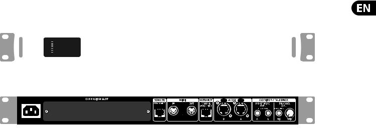
(12)X-USB interface card allows up to 32 channels of bidirectional audio to be transmitted to and from a computer.
(13)ETHERNET connector allows full OSC-based remote control of the X32 CORE.
(14)MIDI IN/OUT allows the unit to send and receive MIDI commands via standard 5-pin DIN cables.
(15)ULTRANET connector sends 16 channels of audio to a P16 monitoring system.
(16)AES50 A and B connectors allow 96 channels of bidirectional audio for connection to S16 digital snakes or other X32 family products. The front panel LEDs will light green to indicate proper sync, light red to indicate a sync error, and remain unlit when no connection is present. Shielded CAT-5e cable should always be used for AES50 connections between X32 and S16 units.
(17)MONITORING OUTPUT jacks allow connection of monitor speakers via balanced or unbalanced 1/4" cables.
(18)TALKBACK input accepts a dynamic microphone via 1/4" TRS jack. Adjust the gain with the adjacent TRIM knob.

6 X32 CORE DIGITAL RACK MIXER User Manual
2. Hookup
Basic Connections
HPX6000
TRS
USB drive for rmware updates, loading
Scenes and playing/recording WAV les
S16 Digital Snake
|
TRS |
TRS |
TRS |
P16D
B3031A Studio monitors
P16M |
Cabling for all AES50 connections between X32 and S16 stageboxes:
•Shielded CAT-5e cable
•Ethercon terminated cable ends
•Maximum cable length 100 meters (330 feet)

7 X32 CORE DIGITAL RACK MIXER User Manual
Multiple Stage Setup with X32 CORE, S16 Snake and P16 Personal Monitor System
P16
Ultranet
|
P16-D Distributor |
|
|
P16-D Distributor |
IEM |
IEM |
|
IEM |
IEM |
Bass Player |
Vocal 1 |
|
2nd Guitarist |
Background Vocal 2 |
IEM |
|
|
IEM |
IEM |
Guitarist |
Keyboardist |
|
Background Vocal |
Background Vocal 3 |
Phones |
|
|
|
IEM |
Drummer |
Voc 1 Floor wedges |
|
Percussionist |
Spare |
POWERPLAY P16-M Digital Personal Mixers |
|
|
|
|
|
Vocal 1 |
P16 |
Keyboards |
Percussion |
|
|
|
|
|
|
|
Ultranet |
|
|
F1320D Active oor monitors
AES50 |
AES50 |
Supermac |
Supermac |
K8 Active Studio Monitors
Analog balanced TRS
Control room with PC application to run both stage setups from one location through the X32 CORE

8X32 CORE DIGITAL RACK MIXER User Manual
3.Select Knob Functions
The SELECT knob serves several functions on the X32 CORE. The following table describes the SELECT knob behavior in each of the available scenarios.
Action |
Functional Description |
Channel Select Mode (SCENE/SETUP button LED is off)
Display |
>Selected channel number |
|
>Input source |
|
>Channel icon and color |
|
>Nickname |
Short press |
Toggles the selected channel to SOLO on/off |
|
> Channel signal will be sent to Monitoring L/R outputs on rear panel and |
|
Phones output on front panel |
|
> Exact behavior depends on settings in Monitoring page |
|
(remote controlled via editing software) |
Rotate |
Immediately selects the desired channel |
|
(input, aux in, FX return, bus, matrix, main or DCA) |
|
>The Channel Type LEDs [5] will follow the selection. |
|
> Note that the X32 CORE Channel Selector will skip all channels, setting |
|
the display color to ’black’ or ’off’. |
Long press |
Clears all active channel solos |
Scene Select Mode (accessed by pressing the SCENE/SETUP button so that the LED is green)
Display |
>“Scene” in bold |
|
>Current scene number |
|
>Next scene number and name (small) to be loaded on GO |
Short press |
Recalls the selected Scene from X32 internal memory “GO” |
|
> behavior depends on Scene settings/preferences (remote controlled via |
|
editing software) |
|
> Scene safes can only be set/reset remotely |
|
> Scenes/Shows from USB drives can only be accessed remotely |
|
>A complete show can be loaded from an attached USB drive into the |
|
internal memory using Setup Mode |
Rotate |
Preselects the next Scene |
Setup Mode (accessed by pressing and holding the SCENE/SETUP button so that the LED is green)
Rotate and press |
Select and enter the Setup pages: |
|
|
1. Load Show |
|
|
2. Contrast |
|
|
3. LEDs |
|
|
4. Clock Rate |
|
|
5. Sync |
|
|
6. IP Address |
|
|
7. IP (Subnet) Mask |
|
|
8. IP Gateway |
|
|
9. Lock |
|
1. Load Show |
Load show from root directory of attached USB drive |
|
|
>display 3 rows: |
|
|
|
-Load Show |
|
|
-Exit |
|
|
-Show Files |
|
>Exit leads back to Setup Mode root level |
|
|
>Turn clockwise to scroll through a list of show files found in USB root |
|
|
directory, push to load selected show and return to Setup Mode root level |
|
2. Contrast |
LCD contrast |
|
|
> Rotate to adjust 0-100 |
|
|
> Press to confirm and exit |
|

9 X32 CORE DIGITAL RACK MIXER User Manual
Action |
Functional Description |
3. LEDs |
LED brightness |
|
> Rotate to adjust 0-100 |
|
> Press to confirm and exit |
4. Clock Rate |
Select the internal Sample Clock Rate |
|
> Rotate to adjust 44.1 or 48 kHz (change requires to reboot the X32 CORE) |
|
> Press to confirm and exit |
5. Sync |
Choose Clock Synchronization source |
|
> Rotate to select INT (internal), AES50 (Port) A, or AES50 (Port) B |
|
> Press to confirm and exit |
6. IP Address |
Select the IP Address for X32 CORE |
|
> Rotate to adjust the first triplet (0-255) |
|
> Press to confirm |
|
> Rotate to adjust the second triplet (0-255) |
|
> Press to confirm |
|
> Rotate to adjust the third triplet (0-255) |
|
> Press to confirm |
|
> Rotate to adjust the fourth triplet (0-255) |
|
> Press to confirm and exit |
7. IP Mask |
Select the IP Subnet Mask for X32 CORE |
|
> Rotate to adjust the first triplet (0-255) |
|
> Press to confirm |
|
> Rotate to adjust the second triplet (0-255) |
|
> Press to confirm |
|
> Rotate to adjust the third triplet (0-255) |
|
> Press to confirm |
|
> Rotate to adjust the fourth triplet (0-255) |
|
> Press to confirm and exit |
8. IP Gateway |
Select the IP Gateway for X32 CORE |
|
> Rotate to adjust the first triplet (0-255) |
|
> Press to confirm |
|
> Rotate to adjust the second triplet (0-255) |
|
> Press to confirm |
|
> Rotate to adjust the third triplet (0-255) |
|
> Press to confirm |
|
> Rotate to adjust the fourth triplet (0-255) |
|
> Press to confirm and exit |
9. Lock |
Locks the X32 CORE |
|
>Display “Lock Cancel” |
|
>Press to cancel locking |
|
> Rotating clockwise turns the display from Green to Red backlight and |
|
shows “LOCKED” |
|
> Press and hold the SCENE/SETUP button for 5 seconds in order to |
|
exit Locked mode and get back to the standard Channel Select mode |
|
(showing the last selected channel) |
Loading...