


User Manual
EURODESK SX4882
Ultra-Low Noise Design 48/24-Input 8-Bus In-Line Mixer with XENYX Mic Preamplifiers, British EQs and Integrated Meterbridge
behringer.com

2 |
EURODESK SX4882 User Manual |
|
Table of Contents |
|
|
Thank you........................................................................ |
2 |
|
Important Safety Instructions....................................... |
3 |
|
Legal Disclaimer.............................................................. |
3 |
|
Limited Warranty............................................................ |
3 |
|
1. Introduction................................................................ |
5 |
|
2. EURODESK Overview................................................. |
6 |
|
3. Input/Output Channel............................................... |
6 |
|
4. Inserts.......................................................................... |
8 |
|
5. Subgroup and Direct Outputs................................... |
9 |
|
6. Master Panel............................................................. |
10 |
|
7. Connections.............................................................. |
13 |
|
8. The Patchfield........................................................... |
17 |
|
9. Equalization.............................................................. |
18 |
|
10. |
Gain Optimization.................................................. |
19 |
11. Impedances and Tuning......................................... |
19 |
|
12. |
(Un)balanced Lines................................................. |
19 |
13. |
Start-up................................................................... |
20 |
14. |
8-track MIDI Suite/Dance Production Studio...... |
21 |
15. |
16-Track Recording with 2 Samplers.................... |
22 |
16. |
Professional 24-Track Studio................................ |
23 |
17. Live P.A. with 2-Track Recording........................... |
24 |
|
18. |
Live Concert with 24-Track Recording.................. |
24 |
19. Expanding the EURODESK..................................... |
25 |
|
20. Timecode................................................................ |
25 |
|
21. Bouncing................................................................. |
26 |
|
22. Input/Output Configuration................................. |
26 |
|
23. Modifications.......................................................... |
26 |
|
24. Specifications......................................................... |
27 |
|
Thank you
Congratulations! With the EURODESK you have acquired a state-of-the-art mixing console that sets new standards. Right from the very start it has been our goal to design a revolutionary unit that can be used for a great variety of applications.
And indeed, this overwhelming mixing console gives you plenty of functionality and a broad range of connection and expansion options.
BEHRINGER is a company with its roots in professional recording studio technology. For many years now we have been successful in developing products for studio and live use. These include microphones and studio gear of all kinds (compressors, enhancers, noise gates, tube processors, headphone amplifiers, digital effects, DI boxes, etc.), monitor and P.A. speakers as well as professional live and recording mixers. Our entire technical know-how has gone into your EURODESK mixing console.
behringer.com
3 EURODESK SX4882 User Manual
Important Safety
Instructions
Terminals marked with this symbol carry electrical current of sufficient magnitude to constitute risk of electric shock. Use only
high-quality commercially-available speaker cables with 1/4" TS plugs pre-installed. All other installation or modification should be performed only by
qualified personnel.
This symbol, wherever it appears, alerts you to the presence of uninsulated dangerous voltage inside the enclosure - voltage that
may be sufficient to constitute a risk of shock.
This symbol, wherever it appears, alerts you to important operating and maintenance instructions in the accompanying literature.
Please read the manual.
Caution
To reduce the risk of electric shock, do not
 remove the top cover (or the rear section). No user serviceable parts inside. Refer servicing to qualified personnel.
Caution
To reduce the risk of fire or electric shock,
 do not expose this appliance to rain and moisture. The apparatus shall not be exposed to dripping or splashing liquids and no objects filled with liquids, such as vases, shall be placed on the apparatus.
Caution
These service instructions are for use
by qualified service personnel only.
To reduce the risk of electric shock do not perform any servicing other than that contained in the operation instructions. Repairs have to be performed by qualified service personnel.
1.Read these instructions.
2.Keep these instructions.
3.Heed all warnings.
4.Follow all instructions.
5.Do not use this apparatus near water.
6.Clean only with dry cloth.
7.Do not block any ventilation openings. Install in accordance with the manufacturer’s instructions.
8.Do not install near any heat sources such as radiators, heat registers, stoves, or other apparatus (including amplifiers) that produce heat.
9.Do not defeat the safety purpose of the polarized or grounding-type plug. A polarized plug has two blades with one wider than the other. A grounding-type plug has two blades and a third grounding prong. The wide
blade or the third prong are provided for your safety. If the provided plug does not fit into your outlet, consult an electrician for replacement of the obsolete outlet.
10.Protect the power cord from being walked on or pinched particularly at plugs, convenience receptacles, and the point where they exit from the apparatus.
11.Use only attachments/accessories specified by
the manufacturer.
12. Use only with the cart, stand, tripod, bracket,
or table specified by the
manufacturer, or sold with the apparatus. When a cart is used, use caution when
moving the cart/apparatus combination to avoid
injury from tip-over.
13.Unplug this apparatus during lightning storms or when unused for long periods of time.
14.Refer all servicing to qualified service personnel. Servicing is required when the apparatus has been damaged in any way, such as power supply cord or plug is damaged, liquid has been spilled or objects have fallen into the apparatus, the apparatus has been exposed
to rain or moisture, does not operate normally, or has been dropped.
15.The apparatus shall be connected to a MAINS socket outlet with a protective earthing connection.
16.Where the MAINS plug or an appliance coupler is used as the disconnect device, the disconnect device shall remain readily operable.
Legal Disclaimer
Technical specifications and appearance are subject to change without notice. The information contained herein is correct at the time of printing. All trademarks are the property of their respective owners. MUSIC Group accepts no liability for any loss which may be suffered by any person who relies either wholly or in part upon any description, photograph or
statement contained herein. Colors and specifications may vary slightly from product. BEHRINGER products are sold through authorized dealers only. Distributors and dealers are not agents of MUSIC Group and have absolutely no authority to bind MUSIC Group by any express or implied undertaking
or representation. This manual is copyrighted. No part of this manual may be reproduced or transmitted in any form or by any means, electronic or mechanical, including photocopying and recording of any kind, for any purpose, without the express written permission of Red Chip Company Ltd.
ALL RIGHTS RESERVED.
© 2010 Red Chip Company Ltd.
Trident Chambers, Wickhams Cay, P.O. Box 146, Road Town, Tortola, British Virgin Islands
Limited Warranty
§ 1 Warranty
[1]This limited warranty is valid only if you purchased the product from a BEHRINGER authorized dealer in the country of purchase. A list of authorized dealers can be found on BEHRINGER’s website behringer.com under “Where to Buy“, or you can contact the BEHRINGER office closest to you.
[2]MUSIC Group* warrants the mechanical and electronic components of this product to be free of defects in material and workmanship if used under normal operating conditions for a period of one (1) year from
the original date of purchase (see the Limited Warranty terms in § 4 below), unless a longer minimum warranty period is mandated by applicable local laws. If the product shows any defects within the specified warranty period and that defect is not excluded under § 4, MUSIC Group shall, at its discretion, either replace or repair the product using suitable new or reconditioned product or parts.
In case MUSIC Group decides to replace the entire product, this limited warranty shall apply to the replacement product for the remaining initial warranty period, i.e., one (1) year (or otherwise applicable minimum warranty period) from the date of purchase of the original product.
[3]Upon validation of the warranty claim, the repaired or replacement product will be returned to the user freight prepaid by MUSIC Group.
[4]Warranty claims other than those indicated above are expressly excluded.
PLEASE RETAIN YOUR SALES RECEIPT. IT IS YOUR PROOF OF PURCHASE COVERING YOUR LIMITED WARRANTY. THIS LIMITED WARRANTY IS VOID WITHOUT SUCH PROOF OF PURCHASE.
§ 2 Online registration
Please do remember to register your new BEHRINGER equipment right after your purchase at behringer.com under“Support” and kindly read the terms and conditions of our limited warranty carefully. Registering your purchase and equipment with us helps us process
your repair claims quicker and more efficiently. Thank you for your cooperation!
§ 3 Return materials authorization
[1] To obtain warranty service, please contact the retailer from whom the equipment was purchased. Should your BEHRINGER dealer not be located in your vicinity, you may contact the BEHRINGER distributor for your country listed under“Support” at behringer.com. If your country is not listed, please check if your problem can be dealt with by our“Online Support” which may also be found under“Support” at behringer.com. Alternatively, please submit an online warranty claim at
behringer.com BEFORE returning the product. All inquiries must be accompanied by a description of the problem and the serial number of the product. After verifying
the product’s warranty eligibility with the original sales receipt, MUSIC Group will then issue a Return Materials Authorization (“RMA”) number.
behringer.com

4EURODESK SX4882 User Manual
[2]Subsequently, the product must be returned in its original shipping carton, together with the return authorization number to the address indicated by MUSIC Group.
[3]Shipments without freight prepaid will not
be accepted.
§ 4 Warranty Exclusions
[1]This limited warranty does not cover consumable parts including, but not limited to, fuses and batteries. Where applicable, MUSIC Group warrants the valves or meters contained in the product to be free from defects in material and workmanship for a period of ninety (90) days from date of purchase.
[2]This limited warranty does not cover the product
if it has been electronically or mechanically modified in any way. If the product needs to be modified or adapted in order to comply with applicable technical or safety standards on a national or local level, in any country which is not the country for which the product was originally developed and manufactured, this
modification/adaptation shall not be considered a defect in materials or workmanship. This limited warranty does not cover any such modification/adaptation, regardless of whether it was carried out properly or not. Under the terms of this limited warranty, MUSIC Group shall not be held responsible for any cost resulting from such a modification/adaptation.
[3]This limited warranty covers only the product hardware. It does not cover technical assistance for hardware or software usage and it does not cover any software products whether or not contained in the product. Any such software is provided“AS IS” unless expressly provided for in any enclosed software limited warranty.
[4]This limited warranty is invalid if the factoryapplied serial number has been altered or removed from the product.
[5]Free inspections and maintenance/repair work
are expressly excluded from this limited warranty, in particular, if caused by improper handling of the product by the user. This also applies to defects caused by normal wear and tear, in particular, of faders, crossfaders, potentiometers, keys/buttons, guitar strings, illuminants and similar parts.
[6] Damage/defects caused by the following conditions are not covered by this limited warranty:
•improper handling, neglect or failure to operate the unit in compliance with the instructions given in BEHRINGER user or service manuals;
•connection or operation of the unit in any way that does not comply with the technical or safety regulations applicable in the country where the product is used;
•damage/defects caused by acts of God/Nature (accident, fire, flood, etc) or any other condition that is beyond the control of MUSIC Group.
[7]Any repair or opening of the unit carried out by unauthorized personnel (user included) will void the limited warranty.
[8]If an inspection of the product by MUSIC Group shows that the defect in question is not covered by the limited warranty, the inspection costs are payable by the customer.
[9]Products which do not meet the terms of this limited warranty will be repaired exclusively at the buyer’s expense. MUSIC Group or its authorized service center will inform the buyer of any such circumstance. If the buyer fails to submit a written repair order within 6 weeks after notification, MUSIC Group will return the unit C.O.D. with a separate invoice for freight and packing. Such costs will also be invoiced separately when the buyer has sent in a written repair order.
[10]Authorized BEHRINGER dealers do not sell new products directly in online auctions. Purchases made through an online auction are on a“buyer beware” basis. Online auction confirmations or sales receipts are not accepted for warranty verification and MUSIC Group will not repair or replace any product purchased through an online auction.
§ 5 Warranty transferability
This limited warranty is extended exclusively to the original buyer (customer of authorized retail dealer) and is not transferable to anyone who may subsequently purchase this product. No other person (retail dealer, etc.) shall be entitled to give any warranty promise on behalf of MUSIC Group.
§ 6 Claim for damage
Subject only to the operation of mandatory applicable local laws, MUSIC Group shall have no liability to the buyer under this warranty for any consequential or indirect
loss or damage of any kind. In no event shall the liability of MUSIC Group under this limited warranty exceed the invoiced value of the product.
§ 7 Limitation of liability
This limited warranty is the complete and exclusive warranty between you and MUSIC Group. It supersedes all other written or oral communications related to this product. MUSIC Group provides no other warranties for this product.
§ 8 Other warranty rights and national law
[1]This limited warranty does not exclude or limit the buyer’s statutory rights as a consumer in any way.
[2]The limited warranty regulations mentioned herein are applicable unless they constitute an infringement of applicable mandatory local laws.
[3]This warranty does not detract from the seller’s obligations in regard to any lack of conformity of the product and any hidden defect.
§ 9 Amendment
Warranty service conditions are subject to change without notice. For the latest warranty terms and conditions
and additional information regarding MUSIC Group’s limited warranty, please see complete details online at behringer.com.
* MUSIC Group Macao Commercial O shore Limited of
Rue de Pequim No. 202-A, Macau Finance Centre 9/J, Macau, including all MUSIC Group companies
behringer.com

5EURODESK SX4882 User Manual
1.Introduction
1.1 The manual
1.1.1 Nomenclature
Most specialist subjects are not really all that difficult provided you understand the language used, and the vocabulary of mixing is pretty straightforward. Nevertheless, it is as well to be clear about what certain terms mean. A “slot” in a recorder will always be referred to as a TRACK, while that in a mixer will invariably be a CHANNEL. A GROUP will always refer to a submix of channels, never a collection of musicians. Similarly the term BAND will be mentioned only in conjunction with FREQUENCY. We will attempt to be as unambiguous as possible with terms, since much confusion can arise from sloppy definitions.
Some terms can have a plurality of meanings. TRACK, in mixing parlance, refers to a tape recorder. In electronic circuits, components on a PCB (printed circuit board) are linked by flat conductors called TRACKS. Hopefully, where terms have different meanings the contexts will be sufficiently diverse so as to avoid any possible confusion.
1.1.2 An unholistic approach
It is virtually impossible to fully explain one aspect of a mixing console
(e.g. CHANNEL ROUTING) without also making it clear what those routes are, where they go, are they migratory, etc. That’s why we have compartmentalized the EURODESK manual into sections, making it easy to find problem solving information and advice. You might find that several cross-sectional references have been made, where areas of interest overlap. E.g.: Channel EQ is specified and described in the “Main equalizer” section 3.4, while EQUALIZATION has its own section, reflecting it’s importance and weight as a subject in its own right.
If we keep repeating ourselves concerning the use of B-channels and the MIX-B bus, it’s because a proper understanding of this area of the board will greatly expand your mixing repertoire.
1.1.3 Key
All DESK functions will be numbered consistently throughout the manual, whether they be in the text or in an illustration. In addition the following prefixes will be used to denote the various types of function control in any illustrations/ text respectively:
Prefix |
Meaning |
S |
Switch |
L |
LED |
P |
Potentiometer |
F |
Fader |
Tab. 1.1: Meaning of the used prefixes |
|
After every prefix you will find the FUNCTION NUMBER. Numbering starts at the top of a CHANNEL, works its way through a stereo GROUP, and finally through the MASTER SECTION. The phantom power and tape operating level switches are not included in the numbering system.
1.2 Before you get started
1.2.1 Shipment
Your product was carefully packed at the factory to ensure safe transport. Nevertheless, if the box is damaged inspect the unit immediately for signs of damage.
◊If the unit is damaged please do NOT return it to us, but notify your dealer and the shipping company immediately; otherwise, claims for damage or replacement may not be granted.
◊We recommend that you use a flight case to give the unit optimum protection during use or transport.
◊Always use the original box to prevent damage during storage or transport.
◊Make sure that children cannot play unsupervised with the unit or its packaging.
◊Please ensure proper disposal of all packing materials.
1.2.2 Initial operation
Ensure adequate air supply and to avoid overheating do not place the unit near radiators etc.
!!Caution
◊Before you change the fuse, switch off the device and pull the plug to avoid electric shock or damage to the device.
◊Blown fuses must be replaced by fuses of the correct rating!
Please refer to the “Specifications” section for the applicable rating.
For connection to the mains use the enclosed power cord with cold connector which complies with the relevant safety regulations.
◊Please make sure that all devices are properly grounded. For your own safety, never remove or disable the ground conductors from the devices or on the power cords. The unit must always be connected to the mains outlet with a protective grounding connection.
Important notes concerning installation
◊The sound quality may diminish within the range of powerful broadcasting stations and high-frequency sources. Increase the distance between the transmitter and the device and use shielded cables for all connections.
1.2.3 Online Registration
Please register your new BEHRINGER equipment right after your purchase by visiting http://behringer.com and read the terms and conditions of our warranty carefully.
Should your BEHRINGER product malfunction, it is our intention to have it repaired as quickly as possible. To arrange for warranty service, please contact the BEHRINGER retailer from whom the equipment was purchased. Should your BEHRINGER dealer not be located in your vicinity, you may directly contact
one of our subsidiaries. Corresponding contact information is included in the original equipment packaging (Global Contact Information/European Contact Information). Should your country not be listed, please contact the distributor nearest you. A list of distributors can be found in the support area of our website (http://behringer.com).
Registering your purchase and equipment with us helps us process your repair claims more quickly and efficiently.
Thank you for your cooperation!
behringer.com
6EURODESK SX4882 User Manual
2.EURODESK Overview
2.1 Architecture
The EURODESK SX4882 is a hybrid SPLIT/INLINE console. Input channels cover most of the surface from the left, while the outputs to tape are to the right. Tape monitor returns, however, are housed within the channel strips, not next to the tape outputs, as would be the case in a conventional “split” design.
This architecture enables much flexibility to be bestowed onto the tape monitor signal path, not least being its ability to pick up functions easily from the main channel. Also, during mixdown, when tape tracks are no longer monitored
but MIXED, the signal path between tape input and main channel is kept to a minimum.
The configuration is 24 into 8 into 24. This means that there are 24 channels, eight subgroups or “submixes” (or four stereo subgroups) and 24 tape monitor returns, one for each channel. There are 24 100 mm channel faders, eight subgroup faders, and a stereo pair of faders driving the L/R main mix.
In remix mode 48 channels are available, all with EQ and access to the aux buses. There are six additional stereo FX returns, giving a grand total of 60 separate line-level inputs: and that’s before you even consider using the subgroup insert points to provide eight more!
There are six aux buses accessed by four potentiometers, two headphone mixes and professional recording, monitoring and talkback facilities. If you can afford to lose the extra 24 line inputs, the MIX-B bus can also act as a separate stereo aux send, giving eight aux buses in all.
A comprehensive set of inputs and outputs include MIC (+48 V), line,
tape (+4 dBu or -10 dBV), inserts all round, direct channel outs and all master recorder and monitoring options. Just about everything you’d expect from a massive console.
In addition, a 1/4" jack expander bay (INPUT ONLY) allows direct patching into all buses within the EURODESK (except PFL and SOLO). Hence two EURODESK consoles may be linked, or the EURODESK coupled to ANY OTHER CONSOLE, large or small, provided that the other console has (or can be MADE to have) similar access (see section 19 “Expanding the EURODESK”).
Last, and probably least, two BNC connectors on top of the built-in meterbridge await optional gooseneck desk lights, available from all good gooseneck desk light stores. A must for those darkened auditoria, or when you’re into your third consecutive night in the studio.
2.2 Metering
The 1 to 24 channels have signal (-20 dB, L 25 ) and overload LEDs (PEAK, L 24 ).
The built-in meterbridge provides 12 segment bargraph meters for all channels and subgroups as well as for the main mix. By the DISPLAY MODE switch
( S 100 , top left of the master section) you decide between CHANNEL and TAPE MODE. Your choice will be indicated by a LED.
In CHANNEL MODE, which is the best for live mixing purposes, the LED meters read the channel’s direct OUTPUT, which is post EQ, post mute and post fader (you may alter that to pre mute and pre fader by the modification described in APPENDIX II.3).
In TAPE MODE the channel meters will mirror the multitrack’s meters, because they read the tape return inputs – after the OPERATING LEVEL switch,
but unaffected by anything else happening in the channel. 0 dB is referenced to the selected tape operating level (+4 dBu or -10 dBV).
The main mix meters double up as mono PFL or stereo SOLO meters, or 2-track return meters, or EXTERNAL return meters (in general, what you HEAR is what you SEE). During PFL/SOLO only the main mix bargraph meters illuminate.
◊In SOLO/PFL mode a 0 dB meter reading matches an internal operating level of 0 dBu (0.775 V). However, when looking at the mix, 0 dB is referenced to +4 dBu, the 2-track operating level. I.e. if only ONE signal is present in the main mix bus, SOLOing that signal will cause the meter reading to increase by +4 dB.
3. Input/Output Channel
3.1 Channel strip
On the EURODESK SX4882 the 24 INPUT + OUTPUT (I/O or “normal”)
channels cover most of the console. Most of each strip is occupied by the main or A-CHANNEL, accepting MIC, LINE or TAPE inputs, depending on the positions of
S 1 and S 3 (see fig. 3.1 and 3.2). Each channel strip also sports a secondary
B-CHANNEL (fig. 3.6) Anything routed to a B-channel is directed to a separate MIX-B bus. (See section 3.7 “B-channel” and also section 6.2 “MIX-B master”).
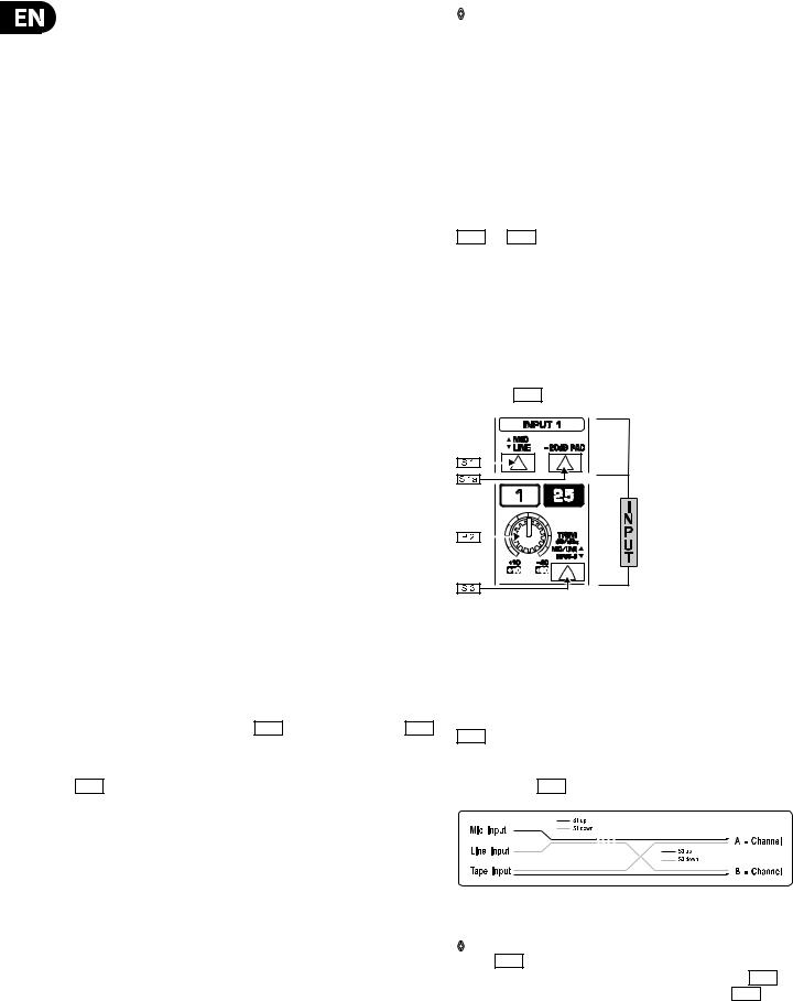
3.2 Input switching
First, look at the MIC/LINE switch |
S 1 |
. In the UP position it selects MIC, in the |
||
DOWN position LINE. The next switch |
|
|
chooses whether A-channel looks at |
|
|
S 3 |
|||
INPUT or TAPE. If INPUT is routed to A-channel, TAPE is offered to B-channel.
If TAPE is routed to A-channel, INPUT is offered to B-channel. Depressing the PAD switch ( S 1a ) lowers an incoming mic signal by -20 dB, if necessary.
Fig. 3.1: Input
When laying tracks, it is usual to use the MIX-B inputs for monitoring the signal from TAPE, while the A-channels take care of microphones, Dl’s, etc. For MIXING purposes, TAPE tracks are normally “flipped” onto the main channels, leaving the B-channels free for other applications, such as offering extra line inputs.
These rules are, however, made to be broken.
S 23 applies to the B-channel only and replaces the normal TAPE or INPUT source with a tap from the main channel, taken post mute and pre fader. Now MIX-B acts as an extra stereo aux send or extra stereo mix. You should remove MIX-B from the main mix (via S 48 , master section) in this configuration.
Fig. 3.2: Channel input switching architecture
◊ The B-channels 25 to 48 are only routable EN BLOC to the main mix, via S 48 . Therefore, the MIX-B bus can only have one function at any one time, either as a stereo AUX or secondary mix send ( S 48 UP) or as a set of 24 extra line or tape inputs to the main mix ( S 48 DOWN).
behringer.com
7EURODESK SX4882 User Manual
3.3Input gain setting
The channel input level is set by the TRIMPOT ( P 2 ). Use SOLO/PFL ( S 26 ) to bring the channel’s input onto the L/R bargraph meters under the master section of the EURODESK SX4882. This also sends the SOLO/PFLed signal to the
left and right speakers. Channel PFL/SOLO ( S 26 ) has an associated LED ( L 26 ). (See also 13.1 “A-channel setting up procedure” and 6.5 “PFL/SOLO”.)
◊ For level-setting (as opposed to localized listening) choose to use the mono PFL rather than the post fader SOLO bus ( S 95 DOWN).
◊SOLO/PFL never interrupts the mix at the main recording outputs. It follows that aux sends and subgroups must also be unaffected, since they can contribute directly to the main mix.
In addition to switchable PFL/SOLO metering, a couple of LEDs ( L 24 and L 25 ) continuously monitor whether a signal is present (-20 dB) or the channel is
going into overload (PEAK). These take their cue from three test points: input, post EQ and post fader. In all cases the higher level wins. You do NOT want the overload light to come on, or if it does no more than very intermittently during a take or a mix.
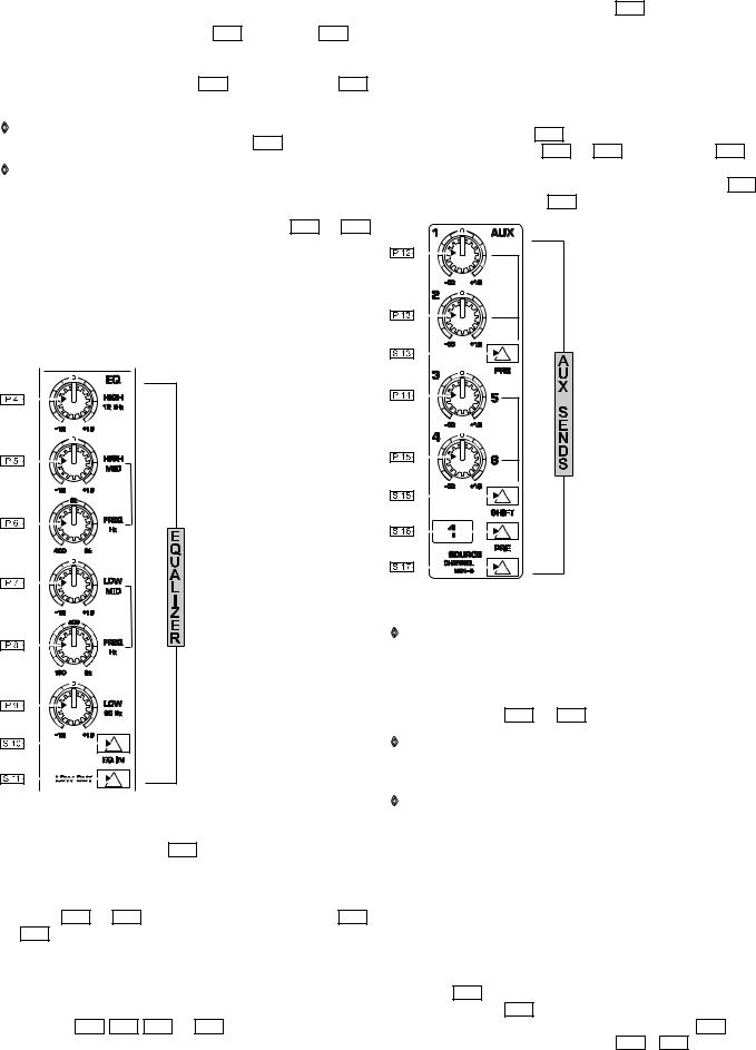
3.4 Main equalizer
Fig. 3.3: Main equalizer
The main equalizer can be switched ( S 10 ) out of circuit for easy A/B
comparisons between EQed and straight signals, or when you know that you don’t want to use desk EQ at all. It is best considered in three sections. First, there are two Baxendall shelving frequency controls for treble and bass, at 12 kHz and 80 Hz respectively ( P 4 and P 9 ). These are DUPLICATED for the B-channel ( P 18
and P 19 ), not merely “SPLIT” off from the main EQ. I.e. you can have a full 4-band EQ on the main channel AND a 2-band EQ on B-channel.
Secondly, there are two semi-parametric swept mids, Q fixed at 1, which cover the bands 300 Hz to 20 kHz and 50 Hz to 3 kHz. An unusually broad frequency range is catered for, and there is an enormous 3-plus octave overlap between the two mid bands ( P 5 , P 6 , P 7 and P 8 ). No experienced engineer will complain about that! All four bands offer 15 dB of cut and boost.
Thirdly, there is a steep high pass (low cut) filter ( S 11 ), slope @ 12 dB/octave, -3 dB @ 75 Hz, for reducing floor rumble, plosives, woolly bottom end, etc.
3.5 Aux sends
All six aux sends are mono and post EQ. They are switchable PRE/POST fader in
two banks ( |
S 13 |
and |
S 16 |
). For aux sends 1 and 2, two dedicated pots |
||
( |
|
and |
|
) are used. These can be taken from a point before or after the |
||
P 12 |
P 13 |
|||||
channel fader, i.e. PRE or POST ( S 13 ). Aux sends 3 and 4, and 5 and 6 are
serviced by two potentiometers ( P 14 and P 15 ). The SHIFT button ( S 15 ) determines whether buses 3 and 4 or 5 and 6 are addressed. Also, these four sends can be derived from the main mix or MIX-B, depending on SOURCE ( S 17 ), and, as before, can be pre or post ( S 16 ).
Fig. 3.4: Aux sends
◊For almost all FX SEND purposes, you will want auxes to be post fader, so that when a fader level is adjusted, any reverb send from that channel follows the fader. Otherwise, when the fader is pulled down, the reverb from that channel would still be audible. For CUEing purposes, aux sends will usually be set pre fader, i.e. independent of
the channel fader ( S 13 and S 16 ).
◊Most reverbs etc. sum up the left and right inputs internally. The very few that don’t may be driven in true stereo either by 1) 2 aux sends or 2) the MIX-B bus (see section 3.7 “B-channel”).
◊There is +15 dB of gain on every aux send. Such a high boost is only appropriate where the channel fader is set around -15 dB or lower. Here, an almost exclusively WET signal will be heard. Previously, in most consoles, such a wet mix required the use of a PRE setting for the channel auxiliary send. This meant losing fader control over the signal.
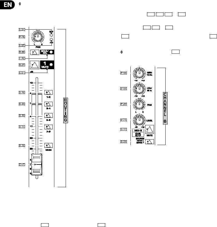
3.6 Routing and muting
ROUTING means selecting which BUS you want a channel to address. There are actually six stereo buses in the EURODESK SX4882 (plus a stereo SOLO bus).
The main mix bus is selected by |
|
S 32 |
(see figure 3.5), while the subgroups |
|||||
are selected by switches |
|
|
(for groups 1 and 2), |
|
(3 and 4), |
|
||
S 28 |
|
S 29 |
S 30 |
|||||
(5 and 6) and S 31 (7 and 8). Odd and even numbered groups are selected via the main A-channel PAN P 24 , as are the left and right mix buses. (The sixth stereo bus is the MIX-B bus, with it’s own independent pan control P 20 ;
see section 3.7 “B-channel”). Usually, only one of S 28 to S 31 will be selected for a particular channel (See block schematics).
behringer.com
8EURODESK SX4882 User Manual
◊An exception to this rule is when laying down voice takes. It is often convenient to have the mic channel(s) routed to alt potential TAKE tracks simultaneously, since you are often dropping in quickly between four or more tracks. It means one less button press each time you switch tracks.
Fig. 3.5: Routing
The level to the subgroup and main mix buses is ultimately determined by the channel faders. These are designed to give a smooth logarithmic taper of a type more usually associated with the name of some pretty expensive brand ...
The low level performance particularly is far smoother than that of a normal “budget” fader.
The MUTE button ( S 27 ), like that for SOLO has an LED indicator ( L 27 ) and removes the A-channel signal from all buses, save any auxes set to pre fader. It is ergonomically placed immediately above the fader and engaging MUTE is equivalent to setting a fader level of minus infinity.
3.7 B-channel
The B-channel (fig. 3.6) comprises a secondary channel with its own high and low EQ, pan and level ( P 18 , P 19 , P 20 and P 21 ). The EQ is a replica of
the A-channel shelving EQ. The B-channel ALWAYS feeds into the MIX-B stereo bus, but its source can be switched between TAPE, LINE, MIC and A-CHANNEL, depending on how S 1 , S 3 and S 23 are set (see fig. 3.2 and section 3.2). Unusually for an 8-bus console, B-channels also have their own MUTE buttons
( S 22 ). Aux sends 3/4/5/6 may be diverted from the A to the B-channel via S 17 .
Therefore, if the B-channel is being used to monitor off-tape, some FX processing e.g. reverb and echo can still be applied. (See section 16.3 “Wet monitoring”.)
◊ When B-channel looks at A-channel ( S 23 DOWN), the signal comes A-channel mute switch and pre fader. A modification can convert this PRE stereo aux send to POST fader. (See 23.2 “MIX-B source > post fader”.)
Fig. 3.6: B-channel |
4. Inserts
Insert points are useful for adding dynamic processing or equalization to a channel, subgroup or the mix. Unlike reverbs, etc., which are usually added to the dry signal, dynamic processing is normally applied across an entire signal. Here, an aux send would be inappropriate. Instead the signal is intercepted somewhere along the channel/subgroup/mix, fed through the dynamics processor and/or EQ and then returned to the console at the same point where it left. The insert point is invisible or normalized, until a jack is plugged into it.
All subgroups and channels have got insert points, as does the main stereo output. Both SEND and RETURN are accommodated on a single stereo 1/4" jack socket wired tip=send, ring=return. Inserts are always pre fader and also pre EQ / aux sends for channels.
Insert points may also be used as pre EQ direct outputs without interrupting the signal flow. This is obvious when looking at the patchbay wiring (section 8,
fig. 8.1). If you want to insert a dynamics processor post EQ, the insert point must either be taken from a subgroup, or via a second channel / aux return as follows:
1)Insert a compressor/gate/EQ across a subgroup, and route the channel to be processed (and only that channel) to that subgroup.
2)Alternatively, patch a channel’s direct out into a compressor/gate/EQ. Take the output from that compressor/gate/EQ and feed it back into the desk via a secondary input (channel, aux return, etc.).
Figure 4.1 illustrates how you might insert into a channel post EQ for mixdown or track-laying (their requirements are different). Mixdown requires one A and one B-channel. Recording requires two A-channels.
behringer.com
9 EURODESK SX4882 User Manual
Fig. 4.1: Post EQ channel insert
◊In this arrangement you might find that compression tends to soften the perceived amount of EQ applied. The solution? Apply more EQ. This creates a real “pressure” sound, great for high energy music such as dance. (For a more subtle approach, use the desk insert points word for word.)
◊Using a group insert to effect post EQ processing precludes the use of POSTPROCESSING AUX SENDS without some serious re-patching.
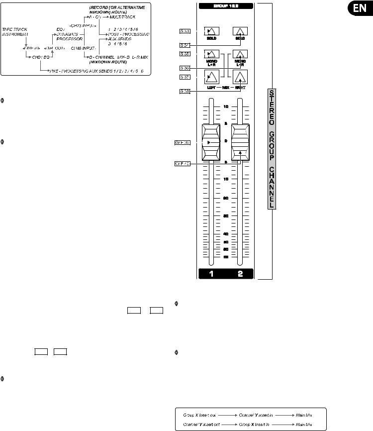
5. Subgroup and Direct Outputs
5.1 Subgroups
The principal routes to the multitrack are via the SUBGROUP OUTPUTS. There are four stereo (or eight mono) subgroups, numbered 1 to 8. All main channels
can access all of them, as can the STEREO AUX RETURNS 1 and 2. (For this reason it is usually wise to bring your best two FX processors back on these returns (or A-channels, for that matter), so that they can easily be sent to tape. (See also section 6.1 “Aux masters”.)
Why are there 16 subgroup output jacks on the EURODESK when there are only
8 subgroups? Well, each subgroup output is duplicated, so that the EURODESK can interface with up to 16 tracks via the group outputs without having to re-patch.
As well as always functioning as subgroups for track laying via the SUBGROUP OUTPUTS, groups can be routed directly into the main mix bus for
submixing. Main mix routing is handled by switches |
S 37 |
and |
S 38 |
. |
S 37 |
routes an odd numbered group to the left bus, while |
|
sends an even |
|||
S 38 |
|||||
numbered subgroup to the right bus. That’s fine for stereo submixes. If you want a pair of mono submixes instead, also press the MONO buttons ( S 35 and S 36 ). Now these subgroups feed into the center of the main mix stereo image, i.e. equally to L and R. You could have the first subgroup feeding into the left hand side, while the second one appears in mono, but we can’t think of many real situations where you’d want to do this.
Subgroup SOLO ( S 33 + S 34 ) follows the mix assignment. E.g.: If the main mix is selected, then that stereo subgroup will be monitored in stereo. If mono is also selected, monitoring is in mono.
◊Try inserting compression / de-essing / an exciter / a gate across grouped signals (e.g. backing vocals, drums, layered synths).
Fig. 5.1: Stereo subgroup channel schematic
◊Try merging a dry signal with a little wet, then compressing the sum heavily. Though the reverb proportion will be low when a signal is present, the resultant reverb tail pumped up by the compressor at the start of each silence will give the illusion that the reverb was massive alt the time. (The listener will be left wondering how the singer could sound so clear in such a wet acoustic!)
◊EURODESK insert points are, of course, simultaneously inputs and outputs. Get them onto a patchbay, where they can appear as independent sockets, and do away with all these fiddly Y leads that always seem to be the first to get knotted in the flightcase.
(See section 8 “The patchfield”.) Now it is possible to do the following incredibly useful patch without having to make up what would amount to a ring-to-tip, tip-to-ring stereo patch lead.
Fig. 5.2: Using insert to add channel EQ to subgroup output (while keeping the number of line inputs unchanged!)
behringer.com
10 EURODESK SX4882 User Manual
5.2 Direct outputs
Each of the 24 main channels on the EURODESK SX4882 has its own DIRECT OUTPUT, which is taken from a point immediately after the fader (i.e. post EQ and after the aux sends, see block schematics). This can feed a tape track directly without having to resort to the subgroups, enabling more than eight different tracks to be recorded simultaneously. Almost alone among the EUROjacks, these are on unbalanced mono sockets at +4 dB. (See section 22 “Input/output configuration”, also section 16.1 “Recording”.)
6. Master Panel
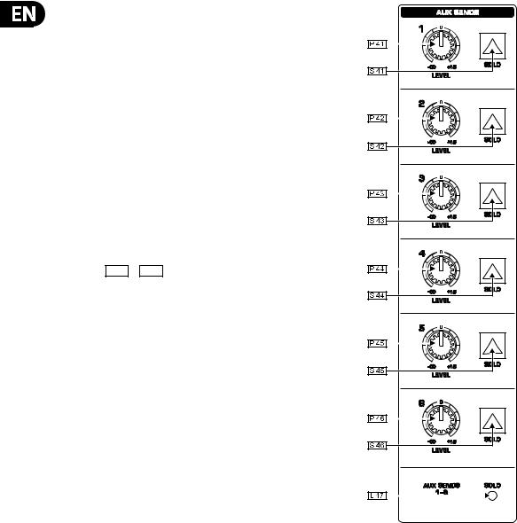
6.1 Aux masters
6.1.1 Aux sends
Much of the master section is taken up by master aux sends and returns. We’ll start with the sends (see fig. 6.1).
Stacked in a vertical column are six master aux send levels, one for each of buses 1 to 6 ( P 41 to P 46 ). Each one has a gain structure of minus infinity to +15 dB. The extra 15 dB of gain comes in once a knob passes a center detente (representing the “normal” unity gain position), enabling insensitive outboard
FX to be properly driven. Each aux send has a SOLO button ( |
|
S 41 |
to |
S 46 |
), |
||
and, as with other areas of mixer, a LOCAL SOLO LIGHT ( |
|
|
), which illuminates |
||||
L 47 |
|
||||||
when any of the AUX master sends are solo-ed. This is to help you see exactly |
|||||||
what has been solo-ed. Any experienced engineer will have had occasion to |
|||||||
search painstakingly through every solo button on his/her console trying to find out why the main solo light was on, and the control room monitors silent!
Fig. 6.1: Aux sends.
behringer.com
 Loading...