


ULTRALINK ULM2000
User’s manual
Version 1.1 |
August 2006 |
|
|
|
|
|
|
|
|
|
|
|
|
|
ULTRALINK ULM2000
IMPORTANT SAFETY INSTRUCTIONS
CAUTION: To reduce the risk of electric shock, do not remove the top cover (or the rear section). No user serviceable parts inside; refer servicing to qualified personnel.
WARNING: To reduce the risk of fire or electric shock, do not expose this appliance to rain and moisture. The apparatus should not be exposed to dripping or splashing and no objects filled with liquids, such as vases, should be placed on the apparatus.
This symbol, wherever it appears, alerts you to the presence of uninsulated dangerous voltage inside the enclosure—voltage that may be sufficient to constitute a risk of shock.
This symbol, wherever it appears, alerts you to important operating and maintenance instructions in the accompanying literature. Please read the manual.
DETAILED SAFETY INSTRUCTIONS:
1)Read these instructions.
2)Keep these instructions.
3)Heed all warnings.
4)Follow all instructions.
5)Do not use this apparatus near water.
6)Clean only with dry cloth.
7)Do not install near any heat sources such as radiators, heat registers, stoves, or other apparatus (including amplifiers) that produce heat.
8)Only use attachments/accessories specified by the manufacturer.
9)Refer all servicing to qualified service personnel. Servicing is required when the apparatus has been damaged in any way, such as power supply cord or plug is damaged, liquid has been spilled or objects have fallen into the apparatus, the apparatus has been exposed to rain or moisture, does not operate normally, or has been dropped.
2

ULTRALINK ULM2000 |
|
TABLE OF CONTENTS |
|
1. INTRODUCTION......................................................................................................... |
3 |
1.1 Before you get started ............................................................................................................ |
4 |
1.1.1 Shipment ....................................................................................................................... |
4 |
1.1.2 Registration ................................................................................................................... |
4 |
1.1.3 Initial operation of the microphone ................................................................................ |
4 |
1.1.4 Online registration ........................................................................................................ |
4 |
2. CONTROL ELEMENTS ............................................................................................... |
5 |
3. HAND-HELD TRANSMITTER OPERATION ................................................................. |
5 |
3.1 Turning the microphone on .................................................................................................... |
5 |
3.2 Channel setting ...................................................................................................................... |
6 |
3.3 Setting your own frequency ................................................................................................. |
6 |
3.4 Preset ..................................................................................................................................... |
7 |
3.5 Mic Gain ................................................................................................................................. |
8 |
3.6 Auto Mute ............................................................................................................................... |
9 |
3.7 Turning the microphone off ................................................................................................... |
9 |
4. STATUS QUERY ....................................................................................................... |
10 |
4.1 Battery condition and transmission channel ....................................................................... |
10 |
4.2 Transmission frequency ...................................................................................................... |
10 |
4.3 Preset ................................................................................................................................... |
10 |
4.4 Mic Gain ............................................................................................................................... |
10 |
4.5 Auto Mute ............................................................................................................................. |
10 |
5. ULM2000 LEVEL SETTING ....................................................................................... |
11 |
6.APPLICATION EXAMPLE .......................................................................................... |
11 |
7. INSTALLATION .......................................................................................................... |
11 |
7.1 Installation information .......................................................................................................... |
11 |
7.2 Audio connections ............................................................................................................... |
12 |
8. SPECIFICATIONS ..................................................................................................... |
12 |
FEDERALCOMMUNICATIONS COMMISSION COMPLIANCE INFORMATION ............. |
13 |
MICROPHONE QUICK START GUIDE ........................................................................... |
14 |
1. INTRODUCTION
Thank you very much for expressing your confidence in us by purchasing the ULTRALINK ULM2000. This Transmitter, coupled to the receiver ULR2000 from BEHRINGER, comprises a modern, high-performance wireless transmission system.
Thanks to its amazing set of features, you can use the ULM2000 in all situations in which the highest sound quality and mobility are a must, e.g. live concerts, events and video productions.
Depending on your local wireless transmission regulations, you can use up to 20 systems simultaneously.
The IRC compander system guarantees an extremely wide transmission dynamic range.
The microphone features a high-quality Panasonic® capsule with a cardioid polar pattern. Therefore, it primarily picks up the sound from the front and less so from the sides. The signal entering the microphone from the back is mostly suppressed. This way, the microphone’s propensity to creating feedback is very negligible, even in live situations.
The ULTRALINK Series equipment features 3 factory presets, each with 8 permanent, interference-free channels. This allows you to use several systems in parallel without them influencing one another. Additionally, you have the option of storing 8 of your own frequencies in a user preset, thus individually addressing your own needs.
1. INTRODUCTION |
3 |

ULTRALINK ULM2000
Determining which microphone is assigned to which receiver is done either by observing the transmission channel in the display or by comparing the transmission frequency. In addition, the ULTRALINK equipment from BEHRINGER leaves you the option to color-code your gear for easy identification.
Beyond that, both units feature other useful functions, such as Scan and Auto Mute. This way, no wishes are left open during practice or in live situations.
The following instructions are intended to familiarize you with the unit’s controls, so that you can learn all of its functions. After having thoroughly read these instructions, store them in a safe place for future reference.
1.1 Before you get started
1.1.1 Shipment
The ULM2000 was carefully packed at the factory to assure secure transportation. Should the condition of the cardboard box suggest that damage may have taken place, please inspect the unit immediately and look for physical indications of damage.
Damaged units should NEVER be sent directly to us. Please inform the dealer from whom you acquired the unit immediately as well as the transportation company from which you took delivery of the unit. Otherwise, all claims for replacement/repair may be rendered invalid.
Always use the original packaging to avoid damage due to storage or shipment.
Never leave children unsupervised with the unit or its packaging.
Please dispose of all packaging materials in an environmentally friendly manner.
1.1.2 Registration
Before powering up the unit for the first time, you have to register it with your local postal/telecommunication authority! Additional information is available there.
1.1.3 Initial operation of the microphone
The ULM2000 microphone requires one or two 9V batteries. Of course, using only one 9V battery decreases the effective uptime. When using only one battery, it does not matter which of the two battery compartments you use. Either one will work.
When running the unit on two batteries, please make sure that both batteries are equally fresh. Therefore, whenever changing batteries, always use two brand-new batteries.
When the battery is nearly depleted, the LED located on the bottom of the microphone will start to blink rapidly. Simultaneously, a special inaudible signal is sent to the ULR2000 receiver, and “LowBat” is shown in its display. To assure dependable operation of the transmitter-receiver system, change the transmitter batteries as soon as possible after seeing the “LowBat” message.
To change the transmitter (mic) batteries:
1.Twist the upper part of the microphone grip while firmly holding its lower portion.
2.Pull the battery compartment out of the microphone until you reach its stop position.
3.Remove the old batteries. Insert one or two fresh 9V batteries.
4.Slide the upper part of the microphone over its lower portion and firmly screw it on.
1.1.4 Online registration
Please do remember to register your new BEHRINGER equipment right after your purchase by visiting www.behringer.com (alternatively www.behringer.de) and kindly read the terms and conditions of our warranty carefully.
Should your BEHRINGER product malfunction, our goal is to have it repaired as quickly as possible. To arrange for warranty service, please contact the retailer from whom the equipment was purchased. Should your BEHRINGER dealer not be located in your vicinity, you may directly contact one of our subsidiaries. Corresponding contact information is included in the original equipment packaging (Global Contact Information/European Contact Information). Should your country not be listed, please contact the distributor nearest you. A list of distributors can be found in the support area of our website (www.behringer.com).
4 |
1. INTRODUCTION |
ULTRALINK ULM2000
Registering your purchase and equipment with us helps us process your repair claims quicker and more efficiently.
Thank you for your cooperation!
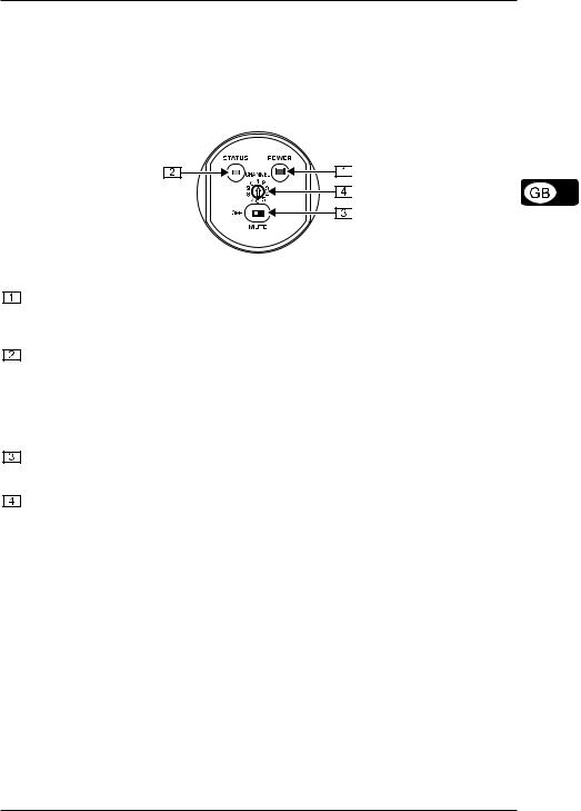
2. CONTROL ELEMENTS
In this chapter, different control elements of your ULM2000 will be described, explained in detail, and you will get useful information on how to use them.
Fig. 2.1: ULM2000’s underside
POWER
To power the hand-held transmitter on or off, keep the POWER button pressed for at least 2 seconds. Briefly pressing the POWER button confirms your choices when entering values (refers to later chapters). Additionally, you can check the current transmitter settings (selected channel and battery condition).
STATUS LED
Through repeated blinking, the status LED gives the account of the current settings for all parameters. We differentiate between 3 different blinking tempos:
The LED blinks slowly when you, for example, successfully leave the programming mode.
To give the account of the channel number or individual frequency values, the LED blinks with medium tempo.
Rapid blinking indicates an error, for example an empty battery or a faulty entry.
MUTE switch
Engaging the MUTE switch mutes the microphone. Additionally, the ULM2000 can be switched to programming mode by selecting the digits 9 or 0; or, you can get a readout of a specific unit setting.
SELECTION SWITCH
Using a screwdriver, you can select different values on the SELECTION SWITCH. For example, you can select a channel number and the frequency.
The SERIAL NUMBER is located on the transmitter battery compartment. To get to the serial number, please open the battery compartment (see ch. 1.1.3).
3. HAND-HELD TRANSMITTER OPERATION
A brief overview with the graphic representation on operating the transmitter is found on the last page of this user manual (QUICK REFERENCE GUIDE).
3.1Turning the microphone on
1.Press the POWER button located at the bottom of the microphone and keep it pressed for 2 seconds.
2.A blink code follows, indicating the battery condition:
1 = Battery is nearly empty . . . |
5 = Battery is fully charged |
3.Afterward, a second blink code indicates to which channel the transmitter is currently set.
1 = channel 1 is selected . . . |
8 = channel 8 is selected |
3. HAND-HELD TRANSMITTER OPERATION |
5 |
 Loading...