


SRC2000
User´s Manual
E
Bedienungsanleitung
Version 1.2 January 1999
D
ULTRAMATCH SRC2000
1

EG-Declaration of Conformity
acc. to the Directives
89/336/EWG and 73/23/EWG
We, BEHRINGER INTERNATIONAL GmbH
Hanns-Martin-Schleyer-Straße 4
D - 47877 Willich
Name and address of the manufacturer or the introducer of the product on the market who is established in the EC
herewith take the sole responsibility to confirm that the product:
ULTRAMATCH SRC2000
Type designation and, if applicable, Article-N
o
Spezielle Studiotechnik GmbH
which refers to this declaration, is in accordance with the following standards or
standardized documents:
x EN 60065 x EN 61000-3-2
x EN 55020 x EN 61000-3-3
x EN 55013 x EN 55022
The following operation conditions and installation arrangements have to be presumed:
acc. to Operating Manual
B. Nier, President Willich, 01.01.1999
Name, address, date and legally binding signature of the person responsible
2

SAFETY INSTRUCTIONS
CAUTION: To reduce the risk of electrical shock, do not remove
the cover (or back). No user serviceable parts inside;
refer servicing to qualified personnel.
WARNING: To reduce the risk of fire or electrical shock, do not
expose this appliance to rain or moisture.
DETAILED SAFETY INSTRUCTIONS:
All the safety and operation instructions should be read before the appliance is operated.
Retain Instructions:
The safety and operating instructions should be retained for future reference.
Heed Warnings:
All warnings on the appliance and in the operating instructions should be adhered to.
Follow instructions:
All operation and user instructions should be followed.
Water and Moisture:
The appliance should not be used near water (e.g. near a bathtub, washbowl, kitchen sink, laundry tub, in a wet
basement, or near a swimming pool etc.).
Ventilation:
The appliance should be situated so that its location or position does not interfere with its proper ventilaton. For
example, the appliance should not be situated on a bed, sofa rug, or similar surface that may block the
ventilation openings: or placed in a built-in installation, such as a bookcase or cabinet that may impede the
flow of air through the ventilation openings.
Heat:
The appliance should be situated away from heat sources such as radiators, heat registers, stoves, or other
appliance (including amplifiers) that produce heat.
Power Source:
The appliance should be connected to a power supply only of the type described in the operating instructions
or as marked on the appliance.
Grounding or Polarization:
Precautions should be taken so that the grounding or polarization means of an appliance is not defeated.
Power-Cord Protection:
Power supply cords should be routed so that they are not likely to be walked on or pinched by items placed
upon or against them, paying particular attention to cords and plugs, convenience receptacles and the point
where they exit from the appliance.
Cleaning:
The appliance should be cleaned only as recommended by the manufacturer.
Non-use Periods:
The power cord of the appliance should be unplugged from the outlet when left unused for a long period of time.
Object and Liquid Entry:
Care should be taken so that objects do not fall and liquids are not spilled into the enclosure through openings.
Damage Requiring Service:
The appliance should be serviced by qualified service personnel when:
- The power supply cord or the plug has been damaged; or
- Objects have fallen, or liquid has been spilled into the appliance; or
- The appliance has been exposed to rain; or
- The appliance does not appear to operate normally or exhibits a marked change in performance; or
- The appliance has been dropped, or the enclosure damaged.
Servicing:
The user should not attempt to service the appliance beyond that is described in the Operating Instructions. All
other servicing should be referred to qualifield service personnel.
E
3

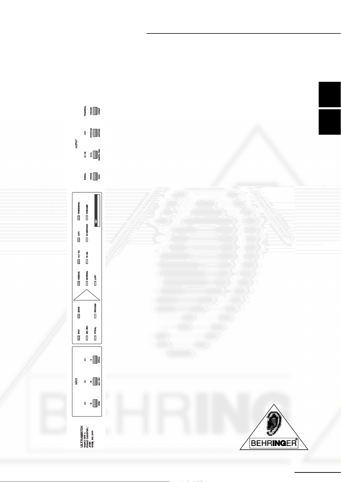
ULTRAMATCH
Provides virtually all possible digital format conversions of professional and consumer modes, AES/EBU, SPDIF coaxial or optical
SRC2000
4

FOREWORD
Dear Customer,
Welcome to the BEHRINGER ULTRAMATCH and thank you for placing your trust in BEHRINGER products.
My most pleasant task is to write this letter to you, because it is the culmination of many months of hard work
for our engineering team. Our daily objective is to be focused on you, the musician and sound engineer, and
with that focus in mind, it drives us to reach a goal which is unique, and is the backbone of the BEHRINGER
philosophy.
It is our philosophy to share our joy with you, because you are the most important member of the Behringer
family. With your highly competent suggestions for new products youve greatly contributed to shaping our
company and making it successful. In return, we guarantee you uncompromising quality (manufactured under
the stringent quality system ISO9000) as well as excellent technical and audio properties at an extremely
favorable price. All of this will enable you to fully unfold your creativity without being hampered by budget
constraints.
We are often asked how we can make it to produce such high-grade devices at such unbelievably low prices.
The answer is quite simple: its you, our customers! Many satisfied customers means large sales volumes
enabling us to get better conditions of purchase for components, etc. Isnt it only fair to pass this benefit back
to you? Because we know that your success is our success, too!
I would like to thank all the people, whose help on the ULTRAMATCH has made it all possible. Everybody has
made very personal contributions, starting from the designers of the unit via the many staff members in my
company to you, the user of BEHRINGER products.
E
Thank you and sincerely yours,
Uli Behringer
5

TABLE OF CONTENT
1. INTRODUCTION ...................................................................................................................... 7
1.1 Some Words on Digital Sample Rate Conversion ........................................................................... 7
1.2 The AES/EBU and SPDIF Standards ..............................................................................................7
2. THE CONCEPT ........................................................................................................................ 9
2.1 The Quality of Components and Circuits ......................................................................................... 9
2.2 Digital Inputs and Outputs ............................................................................................................... 9
2.2.1 XLR ...................................................................................................................................... 9
2.2.2 RCA...................................................................................................................................... 9
2.2.3 Optical (TOSLINK) ................................................................................................................ 9
2.2.4 Wordclock (BNC) ............................................................................................................... 10
3. INSTALLATION ...................................................................................................................... 11
3.1 Rack Mounting ............................................................................................................................... 11
3.2 Mains Connection ..........................................................................................................................11
3.3 General Instructions on Connections ............................................................................................. 11
3.3.1 Balanced XLR Connection (AES / EBU) ..............................................................................11
3.3.2 Unbalanced Coaxial Connections (SPDIF) ......................................................................... 12
3.3.3 Optical Connections (SPDIF) ............................................................................................. 12
3.3.4 Wordclock .......................................................................................................................... 13
3.3.5 Connections with Adapters..................................................................................................14
4. CONTROLS AND FUNCTIONS .............................................................................................. 15
4.1 Front Panel ................................................................................................................................... 15
4.1.1 Input Section ...................................................................................................................... 15
4.1.2 LED-Display ....................................................................................................................... 16
4.1.3 Output Section .................................................................................................................... 17
4.2 Rear Panel .................................................................................................................................... 17
5. MODE OF OPERATION ......................................................................................................... 18
5.1 Basic Settings ............................................................................................................................... 18
5.2 Elimination of Errors ..................................................................................................................... 18
5.3 Conversion to 32 kHz .................................................................................................................... 18
5.4 Emphasis Correction .................................................................................................................... 18
6. APPLICATIONS .....................................................................................................................19
6.1 Sample Rate Conversion ............................................................................................................... 19
6.1.1 Operation in a DAT-Based Studio ....................................................................................... 19
6.1.2 Harddisk Recording ............................................................................................................ 19
6.1.3 Reduction of Memory Requirements ................................................................................... 19
6.1.4 Master/Slave Conflicts ........................................................................................................ 19
6.1.5 Correction of unformatted passages ................................................................................... 20
6.2 SCMS Removal ............................................................................................................................. 20
6.3 Line Booster, Signal Refresher ..................................................................................................... 20
6.4 Sample Rate Correction ................................................................................................................ 20
6.5 Varispeed Applications .................................................................................................................. 21
6.6 Format Conversion ....................................................................................................................... 21
6.7 Format Interface ........................................................................................................................... 21
6.8 Patchbay/Split Operation .............................................................................................................. 21
6.9 The ULTRAMATCH in a home-recording studio............................................................................. 21
7. SPECIFICATIONS .................................................................................................................. 23
8. WARRANTY ...........................................................................................................................25
6

1. INTRODUCTION
BEHRINGER ULTRAMATCH is an essential tool for modern recording studios. The importance of digital
technology has grown immensely during the past years in home-recording as well as in semi-professional
and professional studios. More and more operations are executed on the digital level. As a result, sound
engineers and musicians are confronted with a multitude of new connectors, signal leads, and changed
standards. Incompatibilities between two different devices are normal, and very often it turns out to be
impossible to interconnect two devices from different manufacturers.
This situation made us develop the ULTRAMATCH - a multi-functional device that meets all the requirements
modern studios expect. The ULTRAMATCH combines functions such as a digital patchbay, a signal refresher,
an SCMS eraser, a jitter killer, a format converter, and an excellent sample rate converter within a single unit.
Nevertheless, it is extremely user-friendly.
1.1Some Words on Digital Sample Rate Conversion
Up to now, the conversion of various sample rates has necessitated an enormous amount of components, and
yet has had manifold drawbacks, resulting in measurable signal falsifications such as increased noise, distortion, or unwanted mirror frequencies (high-frequency chirping). The new processor employed in the
ULTRAMATCH executes a real-time conversion with total precision. It works absolutely stealthily, and its
influence on the signal can be detected only by means of very expensive measuring instruments.
Let´s look at a model to explain this operation which describes the conception of interpolation and decimation
of sample points. The processor performs an oversampling on the input signal, i. e. further samples are set
between each two regular samples, resulting in a larger total number of samples by this filling of the gaps. An
equivalent oversampling with a factor of 65,536 corresponds to an internal sample rate of 3.2768 GHz. Afterwards, the signal is run through a variable low-pass filter, ensuring a correct aliasing limit. This process is
started automatically whenever the sample rate at the output falls below the one at the input. Then, the number
of sample points is reduced by division until the desired sample rate can be established at the output. Due to
this enormous oversampling, the processor operates accurately over the entire audio-frequency band. Simultaneously, any jittering present in the input signal is removed.
E
No doubt, digital signal processing provides extremely low THD and noise values. However, signal recalculation especially in sample rate conversion used to lead to considerably non-linear results which is not surprising. The amount of data created in the interpolation model described above would totally overstrain conventional technology. 10 Mbytes of data per minute would have to be stored in standard stereo sampling. Multiplied by 65,536, there would be a data amount of 650 Gbytes! Even if this data were processed in small
packages in order to avoid storage problems, sensible operation would be impracticable. Therefore, programmers have developed various algorithms that always used to be only a compromise between arithmetic expenditure and sound quality.
However, despite real-time data processing, the BEHRINGER ULTRAMATCH obtains fantastic results. The
achieved noise level is below -120 dBFS and the distortion values are below -95 dBFS even at most complex
input signals. That means that the processing executed by the ULTRAMATCH remains inaudible, since
neither conventional A/D and D/A converters nor the final product - the CD - can achieve approximate values.
1.2The AES/EBU and SPDIF Standards
During the past decade, two standards have been established for digital audio transmission (see table 1.1).
The AES/EBU standard defines a professional balanced connection with XLR connectors, whereas the semiprofessional SPDIF standard (developed by Sony and Philips) makes use of RCA or optical connections with
light conductors. However, the SPDIF method standardized in IEC 958 has rather become known for its
notorious copy protection.
1. INTRODUCTION
7
Type AES / EBU IEC 958 (SPDIF)
Connection XLR RCA / Optical
Mode of operation Balanced Unbalanced
Impedance 110 Ohms 75 Ohms
Level 0.2 V to 5 V pp 0.2 V to 0.5 V pp
Clock Accuracy not defined I: ± 50 ppm II: 0,1 % III: Variable Pitch
Jitter ± 20 ns not defined
Tab. 1.1: Important characteristics of the AES/EBU and IEC 958 standards.
Unfortunately, these standards soon became watered-down, since a lot of devices simply did not provide
enough space for XLR jacks. In these units, either TRS jacks, mini jacks, or special adapters for Sub-D
connectors were employed.
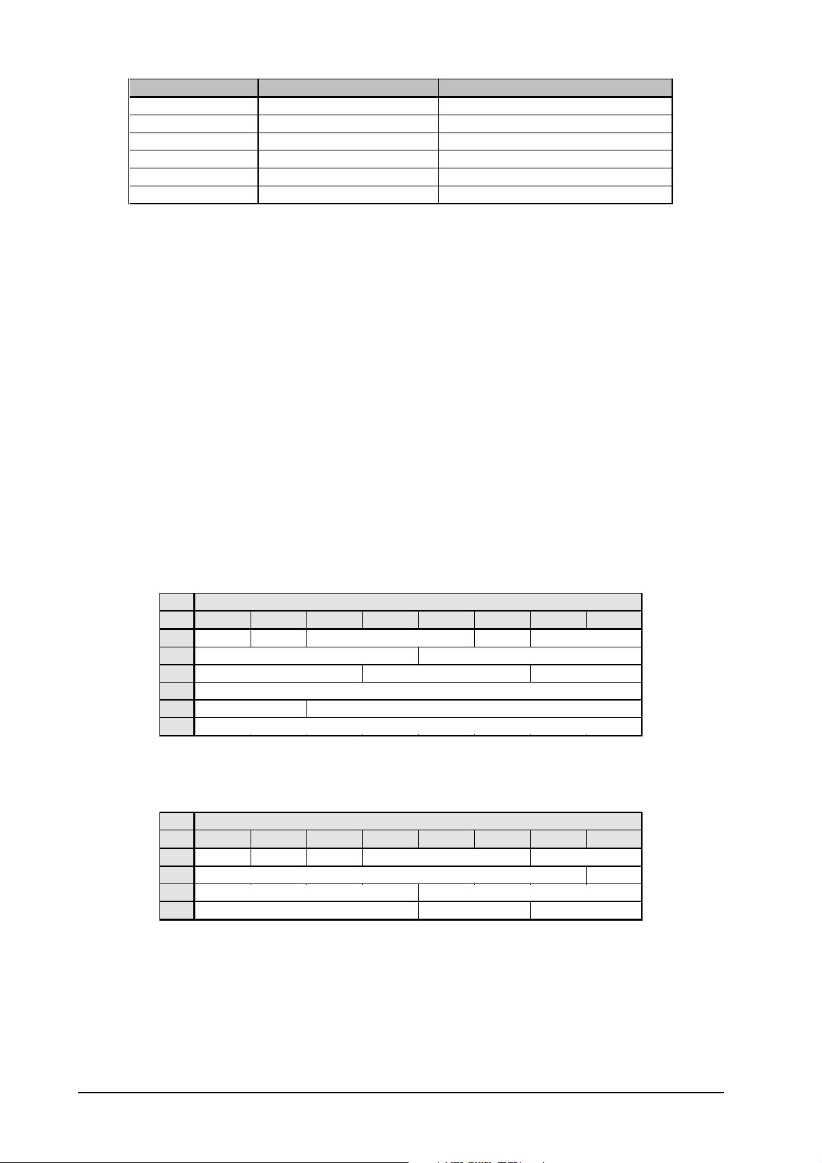
Besides the electrical differences, the physical realizations of the interface concepts are slightly different.
The audio information is transmitted identically, meaning that in principle both formats are compatible. However, there are varying data blocks depending on which format is used. Table 1.2 represents an extract from
the data structure of the AES/EBU standard, table 1.3 shows the corresponding data in SPDIF format. It is
just the first bit that defines the following ones as a professional-type or consumer-type data stream.
It is obvious how the following bits differ in meaning. If a device such as a conventional DAT recorder features
only an SPDIF input, it will accept only SPDIF data. When receiving professional-type data, the data reception
is usually terminated since AES/EBU signals would lead to malfunctions in copy protection and emphasis if
processed by a consumer-type device.
The problem is common to many plug-in connections. A lot of devices do not switch off transmission, others
process both formats though equipped with just one interface type, and finally there are some that are simply
faulty, refusing to operate correctly though the correct identification is received. The ULTRAMATCH is able to
solve any of these problems. Whatever is received by the unit is transmitted from its output as a signal with
correct identification in the selected format.
Byte Bit
01234567
0 P/C Audio?
1
2
3
4
Audio reference Reserved
5
Channel Mode Use of User bit s
Use of AUX bits Length of audio sam pl e Reserved
Reserved for descri pt i on of mult i channel rec ording
Emphasis Locked Sampl . F req.
Reserved
Tab. 1.2: Identifying Information in Professional Format
Byte Bit
01234567
0 P/C Audio? Copy
1
2
3
Sourc e number Channel number
Sampl i ng frequency Clock accuracy Reserved
Category code Gen.S t .
Emphasis Mode
Tab. 1.3: Identifying Information in Consumer Format
8
1. INTRODUCTION
 Loading...